EP4344951A1 - A transparent roof panel assembly for a vehicle roof - Google Patents
A transparent roof panel assembly for a vehicle roof Download PDFInfo
- Publication number
- EP4344951A1 EP4344951A1 EP22198890.0A EP22198890A EP4344951A1 EP 4344951 A1 EP4344951 A1 EP 4344951A1 EP 22198890 A EP22198890 A EP 22198890A EP 4344951 A1 EP4344951 A1 EP 4344951A1
- Authority
- EP
- European Patent Office
- Prior art keywords
- panel
- coupling element
- light
- vehicle
- roof
- Prior art date
- Legal status (The legal status is an assumption and is not a legal conclusion. Google has not performed a legal analysis and makes no representation as to the accuracy of the status listed.)
- Pending
Links
- 238000010168 coupling process Methods 0.000 claims abstract description 127
- 238000005859 coupling reaction Methods 0.000 claims abstract description 127
- 239000000463 material Substances 0.000 claims abstract description 11
- 239000011521 glass Substances 0.000 claims description 40
- 239000012530 fluid Substances 0.000 claims description 14
- 230000008878 coupling Effects 0.000 claims description 3
- 238000000034 method Methods 0.000 claims description 3
- 239000003292 glue Substances 0.000 description 15
- 239000011229 interlayer Substances 0.000 description 12
- 125000006850 spacer group Chemical group 0.000 description 10
- 238000004026 adhesive bonding Methods 0.000 description 5
- 230000005540 biological transmission Effects 0.000 description 4
- 230000003287 optical effect Effects 0.000 description 3
- 230000008901 benefit Effects 0.000 description 2
- 238000010276 construction Methods 0.000 description 2
- 230000006870 function Effects 0.000 description 2
- 239000010410 layer Substances 0.000 description 2
- 239000004417 polycarbonate Substances 0.000 description 2
- 229920000515 polycarbonate Polymers 0.000 description 2
- 239000004820 Pressure-sensitive adhesive Substances 0.000 description 1
- 238000003491 array Methods 0.000 description 1
- 230000000712 assembly Effects 0.000 description 1
- 238000000429 assembly Methods 0.000 description 1
- 239000011324 bead Substances 0.000 description 1
- 230000000740 bleeding effect Effects 0.000 description 1
- 230000008859 change Effects 0.000 description 1
- 230000001419 dependent effect Effects 0.000 description 1
- 230000002349 favourable effect Effects 0.000 description 1
- 239000011888 foil Substances 0.000 description 1
- 238000010438 heat treatment Methods 0.000 description 1
- 230000004048 modification Effects 0.000 description 1
- 238000012986 modification Methods 0.000 description 1
- 238000000465 moulding Methods 0.000 description 1
- 239000002245 particle Substances 0.000 description 1
- 239000002985 plastic film Substances 0.000 description 1
- 230000008569 process Effects 0.000 description 1
- 230000001902 propagating effect Effects 0.000 description 1
- -1 tape Substances 0.000 description 1
Images


Classifications
-
- B—PERFORMING OPERATIONS; TRANSPORTING
- B60—VEHICLES IN GENERAL
- B60Q—ARRANGEMENT OF SIGNALLING OR LIGHTING DEVICES, THE MOUNTING OR SUPPORTING THEREOF OR CIRCUITS THEREFOR, FOR VEHICLES IN GENERAL
- B60Q3/00—Arrangement of lighting devices for vehicle interiors; Lighting devices specially adapted for vehicle interiors
- B60Q3/20—Arrangement of lighting devices for vehicle interiors; Lighting devices specially adapted for vehicle interiors for lighting specific fittings of passenger or driving compartments; mounted on specific fittings of passenger or driving compartments
- B60Q3/208—Sun roofs; Windows
-
- B—PERFORMING OPERATIONS; TRANSPORTING
- B32—LAYERED PRODUCTS
- B32B—LAYERED PRODUCTS, i.e. PRODUCTS BUILT-UP OF STRATA OF FLAT OR NON-FLAT, e.g. CELLULAR OR HONEYCOMB, FORM
- B32B17/00—Layered products essentially comprising sheet glass, or glass, slag, or like fibres
- B32B17/06—Layered products essentially comprising sheet glass, or glass, slag, or like fibres comprising glass as the main or only constituent of a layer, next to another layer of a specific material
- B32B17/10—Layered products essentially comprising sheet glass, or glass, slag, or like fibres comprising glass as the main or only constituent of a layer, next to another layer of a specific material of synthetic resin
- B32B17/10005—Layered products essentially comprising sheet glass, or glass, slag, or like fibres comprising glass as the main or only constituent of a layer, next to another layer of a specific material of synthetic resin laminated safety glass or glazing
- B32B17/10009—Layered products essentially comprising sheet glass, or glass, slag, or like fibres comprising glass as the main or only constituent of a layer, next to another layer of a specific material of synthetic resin laminated safety glass or glazing characterized by the number, the constitution or treatment of glass sheets
- B32B17/10036—Layered products essentially comprising sheet glass, or glass, slag, or like fibres comprising glass as the main or only constituent of a layer, next to another layer of a specific material of synthetic resin laminated safety glass or glazing characterized by the number, the constitution or treatment of glass sheets comprising two outer glass sheets
-
- B—PERFORMING OPERATIONS; TRANSPORTING
- B32—LAYERED PRODUCTS
- B32B—LAYERED PRODUCTS, i.e. PRODUCTS BUILT-UP OF STRATA OF FLAT OR NON-FLAT, e.g. CELLULAR OR HONEYCOMB, FORM
- B32B17/00—Layered products essentially comprising sheet glass, or glass, slag, or like fibres
- B32B17/06—Layered products essentially comprising sheet glass, or glass, slag, or like fibres comprising glass as the main or only constituent of a layer, next to another layer of a specific material
- B32B17/10—Layered products essentially comprising sheet glass, or glass, slag, or like fibres comprising glass as the main or only constituent of a layer, next to another layer of a specific material of synthetic resin
- B32B17/10005—Layered products essentially comprising sheet glass, or glass, slag, or like fibres comprising glass as the main or only constituent of a layer, next to another layer of a specific material of synthetic resin laminated safety glass or glazing
- B32B17/10165—Functional features of the laminated safety glass or glazing
- B32B17/10541—Functional features of the laminated safety glass or glazing comprising a light source or a light guide
-
- B—PERFORMING OPERATIONS; TRANSPORTING
- B62—LAND VEHICLES FOR TRAVELLING OTHERWISE THAN ON RAILS
- B62D—MOTOR VEHICLES; TRAILERS
- B62D25/00—Superstructure or monocoque structure sub-units; Parts or details thereof not otherwise provided for
- B62D25/06—Fixed roofs
Definitions
- the invention relates to a transparent roof panel assembly for a vehicle roof, the roof panel assembly comprising a panel having a transparent area, the panel being configured to be arranged over an opening in the vehicle roof to allow visible light to pass in a first direction through the transparent area, the first direction extending between an exterior of the vehicle and an interior of the vehicle and substantially perpendicular to a surface of the panel, a light source arranged to provide light in the panel in a second direction, an out-coupling pattern arranged on the surface of the transparent area of the panel, the out-coupling pattern is adapted to out-couple light propagating in the panel, and an in-coupling element to in-couple light into the panel from the interior side of the panel, the in-coupling element being attached to the interior side of the panel and redirecting light from the light source into the panel.
- the in-coupling element is partly covered towards the interior of the vehicle, with the exception of a selected area, such that light is able to pass from the in-coupling element towards the interior through the selected area.
- the in-coupling element has an additional function as a light strip visible from the interior of the vehicle.
- the in-coupling element is attached to the interior side of the panel by means of an adhering material accommodated in a chamber formed between the in-coupling element and the panel.
- Such chamber makes it easier to use a proper amount of adhering material, such as tape, glue, gel or the like in the desired position.
- the chamber may be formed by spacers or e.g., by means of clamping parts attached to the interior side of the panel and holding the in-coupling element with respect to the panel at least before the adhering material is introduced into the chamber.
- the in-coupling element is formed directly to the interior side of the panel, either extruded directly on the interior side of the panel or moulded directly to the interior side of the panel.
- the in-coupling element is provided with an extension at the side of the light source and the light source being attached onto this extension of the in-coupling element.
- the extension may be formed to the in-coupling element either at a position adjacent to the interior side of the panel or at a distance from the interior side of the panel in which case the light source is attached to a side of the extension facing the interior side of the panel.
- the in-coupling element may be provided with positioning members to position the light source with respect to the in-coupling element.
- the in-coupling element may be provided with a cover on its side facing the interior of the vehicle, the cover being attached, clipped or taped to the in-coupling element and/or to the interior side of the panel such that also the light source is covered to protect it from view from the interior of the vehicle and/or against moisture.
- the in-coupling element and/or the light source may be attached to the cover, for example, the cover may be moulded or clipped to the in-coupling element and/or to the light source.
- the in-coupling element is divided in its length direction in segments positioned side-by-side such that they are able to move with respect to each other when the panel expands or shrinks in a different manner relative to the in-coupling element due to different thermal expansion coefficients.
- the invention also includes a method of attaching a transparent light transmitting element (for example an in-coupling element) to a glass ply of a transparent roof panel assembly. It comprises the steps of providing the light transmitting element comprising a side having a shape to fit precisely onto the surface of the glass ply, the side being provided with a recess over the majority of its surface and the opposite side of the light transmitting element being provided with a through-hole to the recess, and allowing adhering fluid to enter the recess through the through-hole, the height of the recess being such that the adhering fluid will fill the complete recess due to capillary forces on the fluid within the recess.
- a transparent light transmitting element for example an in-coupling element
- Fig. 1 shows a part of a vehicle, in this case a passenger car, comprising a glass roof construction.
- the vehicle comprises a roof opening 1 in a fixed roof 2.
- the open roof construction has a roof panel assembly including two panels 3, 3' placed adjacent to each other in a longitudinal direction of the vehicle.
- the frontal of the two panels 3, 3' is an openable panel 3 capable of closing and at least partly opening the roof opening 1 of the fixed roof 2.
- the second panel 3' placed rearward of the front panel 3 may be a stationary panel closing the remaining part of the roof opening 1, however it is also conceivable that also the second panel 3' is a movable panel.
- Fig. 2 shows a partial cross-section of a multi-layered panel 3 of the glass roof panel assembly according to Fig. 1 , wherein an exterior glass ply 5 and an interior glass ply 6 are attached by an interlayer 7 and optionally a second interlayer (not shown).
- the interlayer 7 may be formed of EVA or PVB.
- Other materials to form a flexible foil are known and suitable as well as long as the refractive index of the interlayer 7 is lower than that of the interior glass ply 6 if one wishes to keep any light within the glass ply.
- glass has a reflective index of 1.52, EVA and PVB of 1.48.
- a light source 8 is provided at a lower side of the interior or first glass ply 5.
- the light source 8 may be any light source suitable for coupling light 9 into the interior glass ply 6.
- known light sources are LED's directing light directly into lower side of the interior glass ply 6 or, alternatively or additionally, an elongated, side-emitting light guide arranged next to the lower side of the interior glass ply 6.
- An out-coupling pattern is provided at a surface of the interior glass ply 6.
- the out-coupling pattern is arranged at an interface between the interior glass ply 6 and the interlayer 7.
- the interior glass ply 6 and the interlayer 7 are adjacent to each other, which means they are attached directly to each other or through the outcoupling pattern.
- rays of light 9 propagate through the interior glass ply 6 by internal reflection and may impinge on a scattering particle of the out-coupling pattern.
- the ray of light 9 is at least partly reflected and reflected light rays 10 are enabled to leave the interior glass ply 6 at an opposite surface of the interior glass ply 6 and is thus emitted into an interior passenger compartment 11 of the vehicle.
- the light may be in-coupled into the interlayer 7 which includes the out-coupling pattern.
- the outcoupling pattern may be provided on one of the surfaces of the interlayer 7, on the interior glass ply 6 or randomly scattered within the interlayer 7.
- the light source 8 in this case is provided with a base 12 that is attached to the interior side of the interior glass ply.
- a polyhedron-, e.g. prism-shaped, in-coupling element 13 is provided in front of the light source 8 to in-couple light into the panel from the interior side of the panel.
- the in-coupling element 13 is made of e.g., polycarbonate, glass or another transparent, optically clear material which is able to redirect the light from the light source 8 into the interior glass ply 6 of the panel 3.
- a material is used having a refractive index which is equal to or higher than that of the interior glass ply 6 to reduce the size of the optical in-coupling element 13 and maximize the efficiency.
- the entrance of the in-coupling element 13, i.e., the part facing the light source 8 may be lens shaped, either 2D or even 3D to "bundle" the light already in the correct direction (towards the glass at a desired angle) to improve efficiency.
- An additional reflection lens may be provided to reflect light arrays that would otherwise be lost into the correct direction (e.g., parallel to the inclined surface of the in-coupling element).
- Such lens may also be mounted onto the light source, such as a LED.
- the lens shape may also be such that light from the light source 8 can be directed downwardly from the panel 3 (top-emitting LEDs can be used then instead of side-emitting LEDs).
- An additional reflection surface is needed then to direct the light from the downward direction to a direction parallel to the inclined surface of the in-coupling element.
- the in-coupling element 13 is partly covered towards the interior 11 of the vehicle by a cover 14.
- This cover 14 covers the light source 8 with its base 12 and connects to a moulding 15 covering an edge portion of the panel 3.
- the cover 14 also covers the in-coupling element 13, with the exception of a selected area 16, such that light is able to pass directly from the in-coupling element 13 towards the interior 11 of the vehicle through the selected area 16.
- the shape of the in-coupling element 13 is adapted to this additional function including a flat portion onto which an edge of the cover 14 engages and a rounded end as the exposed area 16 where the light may be spread evenly toward the interior 11 of the vehicle.
- the in-coupling element 13 is provided with a graining 16' on its surface in the area 16.
- the in-coupling element 13 is attached to the interior side of interior glass ply 6 of the panel 3.
- Fig. 3a shows a second embodiment related to the manner of attachment of the in-coupling element 13 to the interior side of the panel 3.
- the side of the in-coupling element 13 facing the panel 3 is substantially parallel to the internal glass ply 6 whether it is straight or curved in one or two directions.
- the in-coupling element 13 is provided on its side facing the panel 3 with two spacers: one spacer strip 17 integrated in the in-coupling element 13 and a gluing spacer strip 18 fixed between the in-coupling element 13 and the interior side of the panel 3 at the side of the in-coupling element spaced opposite to the spacer strip 17. In this way there is formed a gluing chamber 4 between the in-coupling element 13 and the interior side of the panel 3 defined by the spacer strips 17 and 18.
- the gluing chamber 4 can be filled beforehand by a gluing tape or a glue bead, or, when already in position on the panel 3, can be injected with glue or gel, or be filled through a capillary process, depending on the viscosity of the fluid. Vacuum may be used (in an autoclave) to extract air bubbles from the glue for better light transmission. To cure the glue, climate or UV-light may be used, or a two-component glue can be used to activate it. It is preferred to use a glue (or other intermediate means of attachment) that has a refractive index that is close to and preferably higher than that of glass, i.e., 1.52 for an optimal light transmission to the interior glass ply 6. Due to the glue, the surface of the in-coupling element 13 does not have to match exactly with the interior surface of the interior glass ply 6, as the glue will create a deformable/adjustable layer between the surfaces.
- Fig. 3b shows a variation of the embodiment of Fig. 3a , in which the integrated spacer strip 17 is replaced by a separate spacer strip similar to the spacer strip 18.
- These spacer strips 17, 18 can be formed by fixation tape, which is particularly useful if a gel is used in the gluing chamber 4 to fix the in-coupling element 13 to the panel 3 which has a lower holding power than glue.
- an optical pressure sensitive adhesive tape can be used. Such tapes provide immediate fixation (some tape need (UV) curing to achieve final properties).
- an interlayer material can be used to fix the optical in-coupling element 13 (such as EVA, PVB, TPU). In combination with the required refractive index TPU is preferred. Such interlayer materials require a temperature/heat treatment to achieve the fixation.
- the joining with tapes or interlayers is preferably done in a vacuum environment (potentially with additional exterior pressure) to avoid air entrapment.
- Fig. 3c shows another variant in which the in-coupling element 13 comprises shoulders 19 and clamping profiles 20 to hold the in-coupling element 13 before, during and after filling the glue chamber 4 with a glue or gel.
- the clamping profiles 20 are attached to the panel 3 but may allow some thermal expansion of the in-coupling element 13 if this is different from that of the panel 3.
- Fig. 4 has an in-coupling element 13 that is integrated in the interior glass ply 6 of the panel 3, either by being directly extruded on the glass ply 6 or by being moulded on the interior side of the interior glass ply 6.
- Fig. 5a shows an embodiment in which the light source 8 with its base 12 is not attached to the panel 3 directly but through the in-coupling element 13.
- the in-coupling element 13 comprises an extension 21 and the base 12 of the light source 8 is mounted onto this extension 21.
- the extension connects to the remainder of the in-coupling element at a position adjacent the panel, so that the attachment of the in-coupling element 13 to the panel 3 also takes place at the position of the extension 21, for example by an adhering tape or layer.
- the extension 21 may be provided with a recess 22 into which the base 12 fits so that the positioning of the light source 8 is facilitated and/or improved.
- This mounting of the light source to the in-coupling element 13 creates a pre-assembled functional light module and avoids glue access from the sides of the in-coupling element towards the critical light source / lens area.
- Fig. 5b shows another embodiment in which the light source 8 is mounted to the in-coupling element 13.
- the extension 21 connects to the remainder of the in-coupling element 13 at a position spaced from the panel 3.
- the extension 21 is provided with a leg 21A extending towards the panel 3 and the free end of which can be attached to the interior side of the interior glass ply 6.
- the light source 8 and its base 12 are now in an upside-down orientation with respect to that of Fig. 5a , so that the light source 8 is attached to the side of the extension 21 facing the panel 3. In this position, it is covered by the extension 21, 21A of the in-coupling element 13.
- Fig. 6a shows a variation of the Fig. 5a embodiment in which the in-coupling element 13 and the light source 8 are covered by another form of the cover 14.
- the cover 14 covers both the in-coupling element 13 and the light source 8 completely so as to prevent the bleeding of light from this area and to protect the light source 8 against mechanical damage and moisture.
- the cover 14 is attached on one side to the panel 3 and on the other side to the in-coupling element 13.
- the cover 14 could e.g., be taped or clipped to the in-coupling element 13 and/or panel 3.
- Fig. 6b shows a variation of the Fig. 6a embodiment in which the cover 14 is precisely attached to the in-coupling element 13 and the base 12 of the light source 8 is attached to the side of the cover 14 facing the panel 3.
- Positioning elements may be provided to position the cover 14 with respect to the in-coupling element 13 and the light source 8.
- the in-coupling element 13 may be over-moulded by the cover 14 or be clipped to it. Other means of fixation are conceivable of course.
- the in-coupling element 13 is also fixed to the panel 3, for example in a manner already described before.
- the base 12 of the light source 8 is over-moulded by or clipped to the cover 14.
- the cover 14 may or may not be moulded or clipped to the in-coupling element 13.
- Figs. 7a - 7d show embodiments that are devised to avoid possible risks resulting from a difference in thermal expansion coefficients of the in-coupling element 13 and glass panel 3.
- the in-coupling element 13 is separated along its length into segments 13' placed side-by-side.
- Each segment 13' has one light source 8 cooperating with it in case of separate light sources such as LEDs.
- the segments 13' could be designed as desired by the relevant thermal expansion coefficients.
- Fig. 7b the separate segments 13' are fixedly coupled for each two light sources 8 and each two segments 13' are interconnected by a flexible connection 23.
- the flexible connections 23 could be integrated within the in-coupling element or could be separate connections attached to the relevant segments 13' of the in-coupling element 13.
- the Fig. 7c embodiment has coupling elements 24 that couple adjacent segments 13' of the in-coupling element 13 with play, so that the coupled adjacent segments 13' can make a slight relative movement upon temperature increases or decrease.
- Fig. 7d shows an embodiment in which the segments 13' are shaped to adapt to the light cone of the respective light sources 8, such that also upon a slight movement of the segments 13' upon a temperature change an obstruction of the light cone is avoided.
- Fig. 8 and 9 show another embodiment of the roof panel assembly.
- Fig. 9 shows that the segment 13' of the in-coupling element 13 is provided on its side facing the glass ply 6 of the panel 3 with a recess 25.
- the height of the recess 25 is very small, e.g., in the range of 0.1 - 0.3mm.
- the recess 25 extends over the majority of the surface area of the respective side of the segment 13'.
- the side of the segment 13' facing away from the panel 3 is provided with a through-hole 26 having a funnelshaped entrance 27.
- the recess 25 is bounded on the short sides of the segment 13' by a groove 28 having a height which is greater than the height of the recess 25.
- Fig. 8 shows that the grooves 28 are inclined in plan-view and communicate with the outside of the segment 13'.
- an adhering fluid is allowed to enter the recess 25 through the through-hole 26
- capillary forces in the recess 25 will force the fluid to fill the entire recess 25 up to the grooves 28 where no capillary forces are created due to the greater height.
- the capillary forces will keep the fluid within the recess 25, only air is allowed to exit through the grooves 28.
- the adhering fluid (glue, gel or the like) will then be cured to fix the segment 13' to the interior glass ply of the panel 3.
- the height of the recess 25 will be adapted to the viscosity of the adhering fluid used.
- the height may vary, e.g., from 0.1 - 0.7 mm.
- a height of 0.2 mm works fine with various glues.
- the invention provides a roof panel assembly in which the panel is lighted by light sources and in-coupling elements that have favourable characteristics, such as versatility, easy and precise attachment, efficient light transmission, easy assembly and others.
- the terms and phrases used herein are not intended to be limiting, but rather to provide an understandable description of the invention.
- the terms "a” or “an”, as used herein, are defined as one or more than one.
- the term plurality, as used herein, is defined as two or more than two.
- the term another, as used herein, is defined as at least a second or more.
- the terms including and/or having, as used herein, are defined as comprising (i.e., open language).
- the term coupled, as used herein, is defined as connected, although not necessarily directly.
- a plastic sheet for example a polycarbonate sheet.
- the invention is also useful in panels having only a single ply.
Abstract
A transparent roof panel assembly for a vehicle roof comprises a panel (3) having a transparent area. The panel is configured to be arranged over an opening (1) in the vehicle roof (2) to allow visible light to pass through the transparent area between an exterior of the vehicle and an interior (11) of the vehicle. A light source (8) is arranged to provide light in the panel. An in-coupling element (13) couples light into the panel from the interior side of the panel, the in-coupling element being attached to the interior side of the panel and redirecting light from the light source into the panel.The in-coupling element (13) may be partly covered towards the interior of the vehicle, with the exception of a selected area (16), such that light is able to pass from the in-coupling element towards the interior (11) through the selected area. The in-coupling element (13) is attached to the interior side of the panel (3) by means of an adhering material accommodated in a chamber (4) formed between the in-coupling element and the panel. The invention includes many more aspects.
Description
- The invention relates to a transparent roof panel assembly for a vehicle roof, the roof panel assembly comprising a panel having a transparent area, the panel being configured to be arranged over an opening in the vehicle roof to allow visible light to pass in a first direction through the transparent area, the first direction extending between an exterior of the vehicle and an interior of the vehicle and substantially perpendicular to a surface of the panel, a light source arranged to provide light in the panel in a second direction, an out-coupling pattern arranged on the surface of the transparent area of the panel, the out-coupling pattern is adapted to out-couple light propagating in the panel, and an in-coupling element to in-couple light into the panel from the interior side of the panel, the in-coupling element being attached to the interior side of the panel and redirecting light from the light source into the panel.
- Such roof panel assembly is known from the prior art.
- It is one of the objects of the present invention to improve the prior art roof panel assemblies.
- According to a first embodiment, the in-coupling element is partly covered towards the interior of the vehicle, with the exception of a selected area, such that light is able to pass from the in-coupling element towards the interior through the selected area.
- In this way, the in-coupling element has an additional function as a light strip visible from the interior of the vehicle.
- In another embodiment, the in-coupling element is attached to the interior side of the panel by means of an adhering material accommodated in a chamber formed between the in-coupling element and the panel.
- Such chamber makes it easier to use a proper amount of adhering material, such as tape, glue, gel or the like in the desired position.
- The chamber may be formed by spacers or e.g., by means of clamping parts attached to the interior side of the panel and holding the in-coupling element with respect to the panel at least before the adhering material is introduced into the chamber.
- In a further embodiment, the in-coupling element is formed directly to the interior side of the panel, either extruded directly on the interior side of the panel or moulded directly to the interior side of the panel.
- This has the advantage of light being guided directly into the panel without borders that may influence the light transmission. Also, one or more assembly steps can be avoided by this embodiment.
- In a further embodiment, the in-coupling element is provided with an extension at the side of the light source and the light source being attached onto this extension of the in-coupling element.
- In this way a pre-assembled functional light module is formed that can be fixed to the panel in one step.
- The extension may be formed to the in-coupling element either at a position adjacent to the interior side of the panel or at a distance from the interior side of the panel in which case the light source is attached to a side of the extension facing the interior side of the panel.
- The in-coupling element may be provided with positioning members to position the light source with respect to the in-coupling element.
- This facilitates assembly and improves the positioning accuracy of the light source with respect to the in-coupling element.
- The in-coupling element may be provided with a cover on its side facing the interior of the vehicle, the cover being attached, clipped or taped to the in-coupling element and/or to the interior side of the panel such that also the light source is covered to protect it from view from the interior of the vehicle and/or against moisture.
- The in-coupling element and/or the light source may be attached to the cover, for example, the cover may be moulded or clipped to the in-coupling element and/or to the light source.
- In a particular embodiment, the in-coupling element is divided in its length direction in segments positioned side-by-side such that they are able to move with respect to each other when the panel expands or shrinks in a different manner relative to the in-coupling element due to different thermal expansion coefficients.
- The invention also includes a method of attaching a transparent light transmitting element (for example an in-coupling element) to a glass ply of a transparent roof panel assembly. It comprises the steps of providing the light transmitting element comprising a side having a shape to fit precisely onto the surface of the glass ply, the side being provided with a recess over the majority of its surface and the opposite side of the light transmitting element being provided with a through-hole to the recess, and allowing adhering fluid to enter the recess through the through-hole, the height of the recess being such that the adhering fluid will fill the complete recess due to capillary forces on the fluid within the recess.
- Further details and advantages of the invention will become clear from the following description with reference to the drawings showing embodiments of the roof panel assembly according to the invention.
-
Fig. 1 is a very schematic plan view of a vehicle roof comprising the roof panel assembly according to the invention. -
Fig. 2 is an enlarged sectional view according to the line II-II inFig. 1 . -
Figs. 3a, b, c ,4, 5a, b and6a, b, c are views similar to that ofFig. 2 but showing different embodiments of the roof panel assembly. -
Figs. 7a, b, c andd show detail VII inFig. 1 , but depicting different embodiments. -
Fig. 8 is a view similar to that ofFig. 7 but showing a further embodiment. -
Fig. 9 is an enlarged sectional view along the line IX-IX inFig. 8 . -
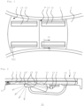
Fig. 1 shows a part of a vehicle, in this case a passenger car, comprising a glass roof construction. The vehicle comprises a roof opening 1 in afixed roof 2. In this case the open roof construction has a roof panel assembly including twopanels 3, 3' placed adjacent to each other in a longitudinal direction of the vehicle. The frontal of the twopanels 3, 3' is anopenable panel 3 capable of closing and at least partly opening theroof opening 1 of the fixedroof 2. The second panel 3' placed rearward of thefront panel 3 may be a stationary panel closing the remaining part of theroof opening 1, however it is also conceivable that also the second panel 3' is a movable panel. Alternatively, it is also conceivable to have just one panel, either fixed or capable of closing and at least partly opening theroof opening 1. -
Fig. 2 shows a partial cross-section of amulti-layered panel 3 of the glass roof panel assembly according toFig. 1 , wherein anexterior glass ply 5 and aninterior glass ply 6 are attached by aninterlayer 7 and optionally a second interlayer (not shown). For example, theinterlayer 7 may be formed of EVA or PVB. Other materials to form a flexible foil are known and suitable as well as long as the refractive index of theinterlayer 7 is lower than that of theinterior glass ply 6 if one wishes to keep any light within the glass ply. For example, glass has a reflective index of 1.52, EVA and PVB of 1.48. - At a lower side of the interior or
first glass ply 5, alight source 8 is provided. Thelight source 8 may be any light source suitable for coupling light 9 into theinterior glass ply 6. For example, known light sources are LED's directing light directly into lower side of theinterior glass ply 6 or, alternatively or additionally, an elongated, side-emitting light guide arranged next to the lower side of theinterior glass ply 6. - An out-coupling pattern is provided at a surface of the
interior glass ply 6. In particular, the out-coupling pattern is arranged at an interface between theinterior glass ply 6 and theinterlayer 7. Theinterior glass ply 6 and theinterlayer 7 are adjacent to each other, which means they are attached directly to each other or through the outcoupling pattern. As shown, rays of light 9 propagate through theinterior glass ply 6 by internal reflection and may impinge on a scattering particle of the out-coupling pattern. Upon impingement, the ray of light 9 is at least partly reflected and reflectedlight rays 10 are enabled to leave theinterior glass ply 6 at an opposite surface of theinterior glass ply 6 and is thus emitted into aninterior passenger compartment 11 of the vehicle. - Other possibilities for the out-coupling pattern exist. For example, the light may be in-coupled into the
interlayer 7 which includes the out-coupling pattern. The outcoupling pattern may be provided on one of the surfaces of theinterlayer 7, on theinterior glass ply 6 or randomly scattered within theinterlayer 7. - The
light source 8 in this case is provided with abase 12 that is attached to the interior side of the interior glass ply. A polyhedron-, e.g. prism-shaped, in-coupling element 13 is provided in front of thelight source 8 to in-couple light into the panel from the interior side of the panel. The in-coupling element 13 is made of e.g., polycarbonate, glass or another transparent, optically clear material which is able to redirect the light from thelight source 8 into theinterior glass ply 6 of thepanel 3. Preferably, a material is used having a refractive index which is equal to or higher than that of theinterior glass ply 6 to reduce the size of the optical in-coupling element 13 and maximize the efficiency. The entrance of the in-coupling element 13, i.e., the part facing thelight source 8 may be lens shaped, either 2D or even 3D to "bundle" the light already in the correct direction (towards the glass at a desired angle) to improve efficiency. An additional reflection lens may be provided to reflect light arrays that would otherwise be lost into the correct direction (e.g., parallel to the inclined surface of the in-coupling element). Such lens may also be mounted onto the light source, such as a LED. The lens shape may also be such that light from thelight source 8 can be directed downwardly from the panel 3 (top-emitting LEDs can be used then instead of side-emitting LEDs). An additional reflection surface is needed then to direct the light from the downward direction to a direction parallel to the inclined surface of the in-coupling element. - In this embodiment, the in-
coupling element 13 is partly covered towards theinterior 11 of the vehicle by acover 14. Thiscover 14 covers thelight source 8 with itsbase 12 and connects to a moulding 15 covering an edge portion of thepanel 3. Thecover 14 also covers the in-coupling element 13, with the exception of aselected area 16, such that light is able to pass directly from the in-coupling element 13 towards theinterior 11 of the vehicle through theselected area 16. The shape of the in-coupling element 13 is adapted to this additional function including a flat portion onto which an edge of thecover 14 engages and a rounded end as the exposedarea 16 where the light may be spread evenly toward theinterior 11 of the vehicle. To better out-couple the light from thisarea 16, the in-coupling element 13 is provided with a graining 16' on its surface in thearea 16. - The in-
coupling element 13 is attached to the interior side of interior glass ply 6 of thepanel 3. -
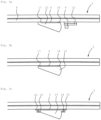
Fig. 3a shows a second embodiment related to the manner of attachment of the in-coupling element 13 to the interior side of thepanel 3. The side of the in-coupling element 13 facing thepanel 3 is substantially parallel to the internal glass ply 6 whether it is straight or curved in one or two directions. The in-coupling element 13 is provided on its side facing thepanel 3 with two spacers: onespacer strip 17 integrated in the in-coupling element 13 and a gluingspacer strip 18 fixed between the in-coupling element 13 and the interior side of thepanel 3 at the side of the in-coupling element spaced opposite to thespacer strip 17. In this way there is formed agluing chamber 4 between the in-coupling element 13 and the interior side of thepanel 3 defined by the spacer strips 17 and 18. The gluingchamber 4 can be filled beforehand by a gluing tape or a glue bead, or, when already in position on thepanel 3, can be injected with glue or gel, or be filled through a capillary process, depending on the viscosity of the fluid. Vacuum may be used (in an autoclave) to extract air bubbles from the glue for better light transmission. To cure the glue, climate or UV-light may be used, or a two-component glue can be used to activate it. It is preferred to use a glue (or other intermediate means of attachment) that has a refractive index that is close to and preferably higher than that of glass, i.e., 1.52 for an optimal light transmission to theinterior glass ply 6. Due to the glue, the surface of the in-coupling element 13 does not have to match exactly with the interior surface of theinterior glass ply 6, as the glue will create a deformable/adjustable layer between the surfaces. -
Fig. 3b shows a variation of the embodiment ofFig. 3a , in which theintegrated spacer strip 17 is replaced by a separate spacer strip similar to thespacer strip 18. These spacer strips 17, 18 can be formed by fixation tape, which is particularly useful if a gel is used in the gluingchamber 4 to fix the in-coupling element 13 to thepanel 3 which has a lower holding power than glue. - Alternatively, an optical pressure sensitive adhesive tape can be used. Such tapes provide immediate fixation (some tape need (UV) curing to achieve final properties). Also an interlayer material can be used to fix the optical in-coupling element 13 (such as EVA, PVB, TPU). In combination with the required refractive index TPU is preferred. Such interlayer materials require a temperature/heat treatment to achieve the fixation. The joining with tapes or interlayers is preferably done in a vacuum environment (potentially with additional exterior pressure) to avoid air entrapment.
-
Fig. 3c shows another variant in which the in-coupling element 13 comprisesshoulders 19 and clampingprofiles 20 to hold the in-coupling element 13 before, during and after filling theglue chamber 4 with a glue or gel. The clamping profiles 20 are attached to thepanel 3 but may allow some thermal expansion of the in-coupling element 13 if this is different from that of thepanel 3. - The embodiment of
Fig. 4 has an in-coupling element 13 that is integrated in the interior glass ply 6 of thepanel 3, either by being directly extruded on theglass ply 6 or by being moulded on the interior side of theinterior glass ply 6. -
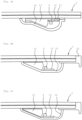
Fig. 5a shows an embodiment in which thelight source 8 with itsbase 12 is not attached to thepanel 3 directly but through the in-coupling element 13. For this purpose, the in-coupling element 13 comprises anextension 21 and thebase 12 of thelight source 8 is mounted onto thisextension 21. The extension connects to the remainder of the in-coupling element at a position adjacent the panel, so that the attachment of the in-coupling element 13 to thepanel 3 also takes place at the position of theextension 21, for example by an adhering tape or layer. Theextension 21 may be provided with arecess 22 into which thebase 12 fits so that the positioning of thelight source 8 is facilitated and/or improved. This mounting of the light source to the in-coupling element 13 creates a pre-assembled functional light module and avoids glue access from the sides of the in-coupling element towards the critical light source / lens area. -
Fig. 5b shows another embodiment in which thelight source 8 is mounted to the in-coupling element 13. In this case theextension 21 connects to the remainder of the in-coupling element 13 at a position spaced from thepanel 3. However, theextension 21 is provided with aleg 21A extending towards thepanel 3 and the free end of which can be attached to the interior side of theinterior glass ply 6. Thelight source 8 and itsbase 12 are now in an upside-down orientation with respect to that ofFig. 5a , so that thelight source 8 is attached to the side of theextension 21 facing thepanel 3. In this position, it is covered by theextension coupling element 13. -
Fig. 6a shows a variation of theFig. 5a embodiment in which the in-coupling element 13 and thelight source 8 are covered by another form of thecover 14. Thecover 14 covers both the in-coupling element 13 and thelight source 8 completely so as to prevent the bleeding of light from this area and to protect thelight source 8 against mechanical damage and moisture. In this case, thecover 14 is attached on one side to thepanel 3 and on the other side to the in-coupling element 13. Of course, it would also be possible to attach thecover 14 at both sides to thepanel 3. Thecover 14 could e.g., be taped or clipped to the in-coupling element 13 and/orpanel 3. -
Fig. 6b shows a variation of theFig. 6a embodiment in which thecover 14 is precisely attached to the in-coupling element 13 and thebase 12 of thelight source 8 is attached to the side of thecover 14 facing thepanel 3. Positioning elements may be provided to position thecover 14 with respect to the in-coupling element 13 and thelight source 8. The in-coupling element 13 may be over-moulded by thecover 14 or be clipped to it. Other means of fixation are conceivable of course. The in-coupling element 13 is also fixed to thepanel 3, for example in a manner already described before. - In the
Fig. 6c embodiment, also thebase 12 of thelight source 8 is over-moulded by or clipped to thecover 14. Thecover 14 may or may not be moulded or clipped to the in-coupling element 13. -
Figs. 7a - 7d show embodiments that are devised to avoid possible risks resulting from a difference in thermal expansion coefficients of the in-coupling element 13 andglass panel 3. - In
Fig. 7a , the in-coupling element 13 is separated along its length into segments 13' placed side-by-side. Each segment 13' has onelight source 8 cooperating with it in case of separate light sources such as LEDs. In case of a continuous light source, such as a light guide, the segments 13' could be designed as desired by the relevant thermal expansion coefficients. - In
Fig. 7b , the separate segments 13' are fixedly coupled for each twolight sources 8 and each two segments 13' are interconnected by aflexible connection 23. Theflexible connections 23 could be integrated within the in-coupling element or could be separate connections attached to the relevant segments 13' of the in-coupling element 13. - The
Fig. 7c embodiment hascoupling elements 24 that couple adjacent segments 13' of the in-coupling element 13 with play, so that the coupled adjacent segments 13' can make a slight relative movement upon temperature increases or decrease. -
Fig. 7d shows an embodiment in which the segments 13' are shaped to adapt to the light cone of therespective light sources 8, such that also upon a slight movement of the segments 13' upon a temperature change an obstruction of the light cone is avoided. -
Fig. 8 and 9 show another embodiment of the roof panel assembly. One recognizes the segments 13' of the in-coupling element 13 and thelight sources 8 on theirbase 12.Fig. 9 shows that the segment 13' of the in-coupling element 13 is provided on its side facing the glass ply 6 of thepanel 3 with arecess 25. The height of therecess 25 is very small, e.g., in the range of 0.1 - 0.3mm. Therecess 25 extends over the majority of the surface area of the respective side of the segment 13'. The side of the segment 13' facing away from thepanel 3 is provided with a through-hole 26 having afunnelshaped entrance 27. Therecess 25 is bounded on the short sides of the segment 13' by agroove 28 having a height which is greater than the height of therecess 25.Fig. 8 shows that thegrooves 28 are inclined in plan-view and communicate with the outside of the segment 13'. - If an adhering fluid is allowed to enter the
recess 25 through the through-hole 26, capillary forces in therecess 25 will force the fluid to fill theentire recess 25 up to thegrooves 28 where no capillary forces are created due to the greater height. The capillary forces will keep the fluid within therecess 25, only air is allowed to exit through thegrooves 28. The adhering fluid (glue, gel or the like) will then be cured to fix the segment 13' to the interior glass ply of thepanel 3. The height of therecess 25 will be adapted to the viscosity of the adhering fluid used. The height may vary, e.g., from 0.1 - 0.7 mm. A height of 0.2 mm works fine with various glues. - It is clear from the above description that the invention provides a roof panel assembly in which the panel is lighted by light sources and in-coupling elements that have favourable characteristics, such as versatility, easy and precise attachment, efficient light transmission, easy assembly and others.
- Detailed embodiments of the present invention are disclosed herein, however, it is to be understood that the disclosed embodiments are merely exemplary of the invention, which can be embodied in various forms. Therefore, specific structural and functional details disclosed herein are not to be interpreted as limiting, but merely as a basis for the claims and as a representative basis for teaching one skilled in the art to variously employ the present invention in expectedly any appropriately detailed structure. In particular, features presented and described in separate dependent claims or in separate embodiments may be applied in combination and any advantageous combination of such claims and embodiments are herewith disclosed.
- Further, the terms and phrases used herein are not intended to be limiting, but rather to provide an understandable description of the invention. The terms "a" or "an", as used herein, are defined as one or more than one. The term plurality, as used herein, is defined as two or more than two. The term another, as used herein, is defined as at least a second or more. The terms including and/or having, as used herein, are defined as comprising (i.e., open language). The term coupled, as used herein, is defined as connected, although not necessarily directly.
- The invention being thus described it is apparent that the same may be varied in many ways. Such variations are not to be regarded as a departure from the spirit and scope of the invention, and all such modifications as would be apparent to one skilled in the art are intended to be included within the scope of the following claims.
- For example, it is possible to replace one or more glass plies in the roof panel assembly by a plastic sheet, for example a polycarbonate sheet. The invention is also useful in panels having only a single ply.
Claims (15)
- A transparent roof panel assembly for a vehicle roof, the roof panel assembly comprising• a panel having a transparent area, the panel being configured to be arranged over an opening in the vehicle roof to allow visible light to pass through the transparent area between an exterior of the vehicle and an interior of the vehicle ,• a light source arranged to provide light in the panel, and• an in-coupling element to in-couple light into the panel from the interior side of the panel, the in-coupling element being attached to the interior side of the panel and redirecting light from the light source into the panel,• wherein the in-coupling element is partly covered towards the interior of the vehicle, with the exception of a selected area, such that light is able to pass from the in-coupling element towards the interior through the selected area.
- A transparent roof panel assembly for a vehicle roof, the roof panel assembly comprising• a panel having a transparent area, the panel being configured to be arranged over an opening in the vehicle roof to allow visible light to pass through the transparent area between an exterior of the vehicle and an interior of the vehicle,• a light source arranged to provide light in the panel, and• an in-coupling element to in-couple light into the panel from the interior side of the panel, the in-coupling element being attached to the interior side of the panel and redirecting light from the light source into the panel,• wherein the in-coupling element is attached to the interior side of the panel by means of an adhering material accommodated in a chamber formed between the in-coupling element and the panel.
- The transparent roof panel assembly of claim 2, wherein the chamber is formed by means of clamping parts attached to the interior side of the panel and holding the in-coupling element with respect to the panel at least before the adhering material is introduced into the chamber.
- A transparent roof panel assembly for a vehicle roof, the roof panel assembly comprising• a panel having a transparent area, the panel being configured to be arranged over an opening in the vehicle roof to allow visible light to pass through the transparent area between an exterior of the vehicle and an interior of the vehicle,• a light source arranged to provide light in the panel, and• an in-coupling element to in-couple light into the panel from the interior side of the panel, the in-coupling element being attached to the interior side of the panel and redirecting light from the light source into the panel,• wherein the in-coupling element is formed directly to the interior side of the panel, either extruded directly on the interior side of the panel or moulded directly to the interior side of the panel.
- A transparent roof panel assembly for a vehicle roof, the roof panel assembly comprising• a panel having a transparent area, the panel being configured to be arranged over an opening in the vehicle roof to allow visible light to pass through the transparent area between an exterior of the vehicle and an interior of the vehicle,• a light source arranged to provide light in the panel, and• an in-coupling element to in-couple light into the panel from the interior side of the panel, the in-coupling element being attached to the interior side of the panel and redirecting light from the light source into the panel,• wherein the in-coupling element is provided with an extension at the side of the light source and the light source being attached onto this extension of the in-coupling element.
- The transparent roof panel assembly of claim 5, wherein the extension is formed to the in-coupling element at a distance from the interior side of the panel such that the light source is attached to a side of the extension facing the interior side of the panel.
- The transparent roof panel assembly of claim 5 or 6, wherein the in-coupling element is provided with positioning members to position the light source with respect to the in-coupling element.
- A transparent roof panel assembly for a vehicle roof, the roof panel assembly comprising• a panel having a transparent area, the panel being configured to be arranged over an opening in the vehicle roof to allow visible light to pass through the transparent area between an exterior of the vehicle and an interior of the vehicle,• a light source arranged to provide light in the panel in a second direction, and• an in-coupling element to in-couple light into the panel from the interior side of the panel, the in-coupling element being attached to the interior side of the panel and redirecting light from the light source into the panel,• wherein the in-coupling element is provided with a cover on its side facing the interior of the vehicle, the cover being attached to the in-coupling element and/or to the interior side of the panel such that also the light source is covered to protect it from view from the interior of the vehicle.
- The transparent roof panel assembly of claim 8, wherein the in-coupling element and/or the light source is attached to the cover
- The transparent roof panel assembly of claim 9, wherein the cover is moulded or clipped to the in-coupling element and/or to the light source.
- A transparent roof panel assembly for a vehicle roof, the roof panel assembly comprising• a panel having a transparent area, the panel being configured to be arranged over an opening in the vehicle roof to allow visible light to pass through the transparent area between an exterior of the vehicle and an interior of the vehicle,• a light source arranged to provide light in the panel, and• an in-coupling element to in-couple light into the panel from the interior side of the panel, the in-coupling element being attached to the interior side of the panel and redirecting light from the light source into the panel,• wherein the in-coupling element is divided in its length direction in segments positioned side-by-side such that they are able to move with respect to each other when the panel expands or shrinks.
- The transparent roof panel assembly of claim 11, wherein the segments of the in-coupling element are connected to each other by flexible area's formed in one piece with the segments, or are coupled to each other through coupling members allowing limited movement between the segments.
- The transparent roof panel assembly of claim 11 or 12, wherein the segments of the in-coupling element are coneshaped adapted to the cone-shape of the light of the adjacent light source.
- A transparent roof panel assembly for a vehicle roof, the roof panel assembly comprising• a panel having a transparent area, the panel being configured to be arranged over an opening in the vehicle roof to allow visible light to pass through the transparent area between an exterior of the vehicle and an interior of the vehicle,• a light source arranged to provide light in the panel, and• an in-coupling element to in-couple light into the panel from the interior side of the panel, the in-coupling element being attached to the interior side of the panel and redirecting light from the light source into the panel,• wherein the in-coupling element is provided with a recess at its side facing the interior side of the panel and extending the majority of the surface of the side of the in-coupling element, the opposite side of the in-coupling element being provided with a through-hole to allow the entrance of adhering fluid into the recess, the height of the recess being such that capillary forces will force the adhering fluid to fill the complete recess, and wherein preferably the recess is bounded on at least two opposite ends with a groove having a greater height than the recess and communicating with the outside of the in-coupling element.
- A method of attaching a transparent light transmitting element, such as an in-coupling element, to a glass ply of a transparent roof panel assembly, comprising the steps of:providing the light transmitting element comprising a side having a shape to fit onto the surface of the glass ply, the side being provided with a recess over the majority of its surface and the opposite side of the light transmitting element being provided with a through-hole to the recess, andallowing adhering fluid to enter the recess through the through-hole, the height of the recess being such that the adhering fluid will fill the complete recess due to capillary forces on the fluid within the recess.
Priority Applications (3)
| Application Number | Priority Date | Filing Date | Title |
|---|---|---|---|
| EP22198890.0A EP4344951A1 (en) | 2022-09-29 | 2022-09-29 | A transparent roof panel assembly for a vehicle roof |
| CN202310635991.XA CN117774631A (en) | 2022-09-29 | 2023-05-31 | Transparent roof panel assembly for a vehicle roof |
| US18/326,346 US20240109482A1 (en) | 2022-09-29 | 2023-05-31 | Transparent roof panel assembly for a vehicle roof |
Applications Claiming Priority (1)
| Application Number | Priority Date | Filing Date | Title |
|---|---|---|---|
| EP22198890.0A EP4344951A1 (en) | 2022-09-29 | 2022-09-29 | A transparent roof panel assembly for a vehicle roof |
Publications (1)
| Publication Number | Publication Date |
|---|---|
| EP4344951A1 true EP4344951A1 (en) | 2024-04-03 |
Family
ID=83508727
Family Applications (1)
| Application Number | Title | Priority Date | Filing Date |
|---|---|---|---|
| EP22198890.0A Pending EP4344951A1 (en) | 2022-09-29 | 2022-09-29 | A transparent roof panel assembly for a vehicle roof |
Country Status (3)
| Country | Link |
|---|---|
| US (1) | US20240109482A1 (en) |
| EP (1) | EP4344951A1 (en) |
| CN (1) | CN117774631A (en) |
Citations (9)
| Publication number | Priority date | Publication date | Assignee | Title |
|---|---|---|---|---|
| DE202014104932U1 (en) * | 2014-10-16 | 2015-01-30 | Jens Junek | Lighting arrangement and arrangement of a car window for a vehicle and such a lighting arrangement |
| DE202018103669U1 (en) * | 2017-06-29 | 2018-07-12 | Ford Global Technologies, Llc | Lighting conductor integrated inside a sunroof paneling ring |
| DE102018008228A1 (en) * | 2018-10-17 | 2020-04-23 | Daimler Ag | Lighting device for an interior of a vehicle |
| DE102020101813A1 (en) * | 2019-01-29 | 2020-07-30 | Schott Ag | Line light |
| US20200384740A1 (en) * | 2017-11-30 | 2020-12-10 | Saint-Gobain Glass France | External luminous signaling vehicle glazing, vehicle incorporating same and manufacture |
| CN112677880A (en) * | 2020-12-18 | 2021-04-20 | 福耀玻璃工业集团股份有限公司 | Atmosphere window and vehicle |
| DE102020109338B3 (en) * | 2020-04-03 | 2021-05-27 | Webasto SE | Vehicle window with light source and light guide layer |
| US20210170724A1 (en) * | 2017-03-31 | 2021-06-10 | Saint-Gobain Glass France | Illuminating glazing unit |
| WO2023031460A1 (en) * | 2021-09-06 | 2023-03-09 | Webasto SE | Vehicle pane with a lighting device |
-
2022
- 2022-09-29 EP EP22198890.0A patent/EP4344951A1/en active Pending
-
2023
- 2023-05-31 CN CN202310635991.XA patent/CN117774631A/en active Pending
- 2023-05-31 US US18/326,346 patent/US20240109482A1/en active Pending
Patent Citations (9)
| Publication number | Priority date | Publication date | Assignee | Title |
|---|---|---|---|---|
| DE202014104932U1 (en) * | 2014-10-16 | 2015-01-30 | Jens Junek | Lighting arrangement and arrangement of a car window for a vehicle and such a lighting arrangement |
| US20210170724A1 (en) * | 2017-03-31 | 2021-06-10 | Saint-Gobain Glass France | Illuminating glazing unit |
| DE202018103669U1 (en) * | 2017-06-29 | 2018-07-12 | Ford Global Technologies, Llc | Lighting conductor integrated inside a sunroof paneling ring |
| US20200384740A1 (en) * | 2017-11-30 | 2020-12-10 | Saint-Gobain Glass France | External luminous signaling vehicle glazing, vehicle incorporating same and manufacture |
| DE102018008228A1 (en) * | 2018-10-17 | 2020-04-23 | Daimler Ag | Lighting device for an interior of a vehicle |
| DE102020101813A1 (en) * | 2019-01-29 | 2020-07-30 | Schott Ag | Line light |
| DE102020109338B3 (en) * | 2020-04-03 | 2021-05-27 | Webasto SE | Vehicle window with light source and light guide layer |
| CN112677880A (en) * | 2020-12-18 | 2021-04-20 | 福耀玻璃工业集团股份有限公司 | Atmosphere window and vehicle |
| WO2023031460A1 (en) * | 2021-09-06 | 2023-03-09 | Webasto SE | Vehicle pane with a lighting device |
Also Published As
| Publication number | Publication date |
|---|---|
| CN117774631A (en) | 2024-03-29 |
| US20240109482A1 (en) | 2024-04-04 |
Similar Documents
| Publication | Publication Date | Title |
|---|---|---|
| US20230118480A1 (en) | Vehicle Window Pane Comprising a Light Source and a Light-Conducting Layer | |
| CN108990414B (en) | Illuminated glazing unit | |
| US9630551B2 (en) | Light-emitting diode module for a vehicle, and productions | |
| US9006751B2 (en) | Luminous vehicle glazing and manufacture thereof | |
| US8829539B2 (en) | Luminous vehicle glazing and manufacture thereof | |
| JP6199863B2 (en) | Luminous glazing for vehicles and method for manufacturing the same | |
| EP2548769B1 (en) | Automotive rear light | |
| US20110273874A1 (en) | Light-emitting diode module for a vehicle, and diode mounting | |
| KR20070003938A (en) | A light-guiding device and a method of guiding light | |
| CN104603529B (en) | Illuminate glass pane | |
| CN112677575A (en) | Light guide skylight assembly | |
| JP2020500398A (en) | Light deflection devices, daylighting devices, and uses | |
| EP4344951A1 (en) | A transparent roof panel assembly for a vehicle roof | |
| KR20240045072A (en) | A transparent roof panel assembly for a vehicle roof | |
| US20190176691A1 (en) | Open roof construction for a vehicle | |
| CN113370760A (en) | Rear windshield subassembly and car | |
| CN220576772U (en) | Glass panel assembly | |
| WO2024033772A1 (en) | Glazing having a light injection assembly | |
| US11867942B1 (en) | Encapsulated illuminated automotive glazing and method of producing thereof | |
| CN219606854U (en) | Lighting unit, glass assembly and window assembly | |
| US20230086792A1 (en) | Vehicle window structure | |
| CN215850676U (en) | Light emitting device for sunroof | |
| CN219446853U (en) | Automobile skylight glass assembly and automobile skylight | |
| CN117063087A (en) | Exterior component for a vehicle, vehicle and method for producing an exterior component | |
| CN117015472A (en) | Illuminated composite glass sheet with reflective edge coating |
Legal Events
| Date | Code | Title | Description |
|---|---|---|---|
| PUAI | Public reference made under article 153(3) epc to a published international application that has entered the european phase |
Free format text: ORIGINAL CODE: 0009012 |
|
| STAA | Information on the status of an ep patent application or granted ep patent |
Free format text: STATUS: THE APPLICATION HAS BEEN PUBLISHED |
|
| AK | Designated contracting states |
Kind code of ref document: A1 Designated state(s): AL AT BE BG CH CY CZ DE DK EE ES FI FR GB GR HR HU IE IS IT LI LT LU LV MC MK MT NL NO PL PT RO RS SE SI SK SM TR |