EP4344832A1 - Horizontal articulated robot - Google Patents
Horizontal articulated robot Download PDFInfo
- Publication number
- EP4344832A1 EP4344832A1 EP23200199.0A EP23200199A EP4344832A1 EP 4344832 A1 EP4344832 A1 EP 4344832A1 EP 23200199 A EP23200199 A EP 23200199A EP 4344832 A1 EP4344832 A1 EP 4344832A1
- Authority
- EP
- European Patent Office
- Prior art keywords
- arm
- motor
- articulated robot
- horizontal articulated
- base
- Prior art date
- Legal status (The legal status is an assumption and is not a legal conclusion. Google has not performed a legal analysis and makes no representation as to the accuracy of the status listed.)
- Pending
Links
Images




Classifications
-
- B—PERFORMING OPERATIONS; TRANSPORTING
- B25—HAND TOOLS; PORTABLE POWER-DRIVEN TOOLS; MANIPULATORS
- B25J—MANIPULATORS; CHAMBERS PROVIDED WITH MANIPULATION DEVICES
- B25J9/00—Program-controlled manipulators
- B25J9/02—Program-controlled manipulators characterised by movement of the arms, e.g. cartesian coordinate type
- B25J9/04—Program-controlled manipulators characterised by movement of the arms, e.g. cartesian coordinate type by rotating at least one arm, excluding the head movement itself, e.g. cylindrical coordinate type or polar coordinate type
- B25J9/041—Cylindrical coordinate type
- B25J9/042—Cylindrical coordinate type comprising an articulated arm
-
- B—PERFORMING OPERATIONS; TRANSPORTING
- B25—HAND TOOLS; PORTABLE POWER-DRIVEN TOOLS; MANIPULATORS
- B25J—MANIPULATORS; CHAMBERS PROVIDED WITH MANIPULATION DEVICES
- B25J9/00—Program-controlled manipulators
- B25J9/10—Program-controlled manipulators characterised by positioning means for manipulator elements
- B25J9/102—Gears specially adapted therefor, e.g. reduction gears
-
- B—PERFORMING OPERATIONS; TRANSPORTING
- B25—HAND TOOLS; PORTABLE POWER-DRIVEN TOOLS; MANIPULATORS
- B25J—MANIPULATORS; CHAMBERS PROVIDED WITH MANIPULATION DEVICES
- B25J9/00—Program-controlled manipulators
- B25J9/10—Program-controlled manipulators characterised by positioning means for manipulator elements
- B25J9/104—Program-controlled manipulators characterised by positioning means for manipulator elements with cables, chains or ribbons
-
- B—PERFORMING OPERATIONS; TRANSPORTING
- B25—HAND TOOLS; PORTABLE POWER-DRIVEN TOOLS; MANIPULATORS
- B25J—MANIPULATORS; CHAMBERS PROVIDED WITH MANIPULATION DEVICES
- B25J9/00—Program-controlled manipulators
- B25J9/10—Program-controlled manipulators characterised by positioning means for manipulator elements
- B25J9/104—Program-controlled manipulators characterised by positioning means for manipulator elements with cables, chains or ribbons
- B25J9/1045—Program-controlled manipulators characterised by positioning means for manipulator elements with cables, chains or ribbons comprising tensioning means
Definitions
- the present disclosure relates to a horizontal articulated robot.
- JP-A-2005-125489 discloses a SCARA robot that a belt, a deflecting device, or the like are eliminated by disposing an actuating motor in a second robot arm, reducing weight of the robot arm and reducing the inertia moment.
- a horizontal articulated robot includes a base; a first arm coupled to the base and configured to pivot about a first pivot axis; a second arm coupled to the first arm and configured to pivot about a second pivot axis, which is parallel to the first pivot axis; a first motor configured to drive the first arm; and a second motor configured to drive the second arm, wherein the first motor and the second motor are disposed in the base, and a driving force of the second motor is transmitted to the second arm via a belt provided inside the first arm.
- a horizontal articulated robot 1 will be described with reference to FIGS. 1 and 2 .
- an X-axis, a Y-axis, and a Z-axis are illustrated in the following drawings as three axes orthogonal to each other.
- a direction along the X axis is referred to as an "X direction”
- a direction along the Y axis is referred to as a "Y direction”
- a direction along the Z axis is referred to as a "Z direction”.
- the arrow tip end side of each axis is also referred to as a "plus side”
- the side opposite to the arrow is also referred to as a "minus side”.
- the positive side in the Z direction is also referred to as "above” and the negative side in the Z direction is also referred to as "below”.
- the horizontal articulated robot 1 includes, as shown in FIGS. 1 and 2 , a base 10, a first arm 11 coupled to the base 10 and configured to pivot about a first pivot axis F1, a second arm 12 coupled to the first arm 11 and configured to pivot about the second pivot axis F2, which is parallel to the first pivot axis F1, a third arm 13 that rotates around a third pivot axis F3, which is parallel to the second pivot axis F2, and that drives in a direction along the third pivot axis F3, a first motor 21 configured to drive the first arm 11, a second motor 22 configured to drive the second arm 12, a third motor 23 configured to drive the third arm 13, and a fourth motor 24 configured to drive the third arm 13 in the vertical direction.
- the horizontal articulated robot 1 is fixed to a floor or the like via a mounting base 14 coupled to the base 10.
- the first pivot axis F1, the second pivot axis F2, and the third pivot axis F3 are orthogonal to the XY plane, which is a horizontal plane.
- the third pivot axis F3 coincides with the central axis of the third arm 13.
- the base 10 is coupled to the first arm 11, and includes a first motor 21 that drives the first arm 11, a second motor 22 that drives the second arm 12, and a control section 20 that controls the first arm 11, the second arm 12, and a spindle arm 13.
- the first motor 21 and the second motor 22 are disposed separated from each other above and below the first arm 11, and in the present embodiment, the first motor 21 is disposed below the first arm 11. Therefore, a heavy motor having a large output can be used as the first motor 21 at the lower part of the base 10, and the horizontal articulated robot 1 can be stably fixed with a good balance.
- the first arm 11 is coupled to the base 10 and is pivoted around the first pivot axis F1 by the first motor 21, which is disposed in the base 10.
- a first decelerator 41 coupled to the first motor 21 is provided in the first arm 11. Rotation of the first motor 21 is input to the first decelerator 41, and the first decelerator 41 has a function of outputting torque corresponding to a speed reduction ratio while reducing the speed of the input rotation using a plurality of gears having different numbers of teeth. That is, the output is amplified by reducing the rotational speed of the input.
- the rotational axis of the first motor 21 and the rotational axis of the first decelerator 41 coincide with the first pivot axis F1, and the first arm 11 pivots around the first pivot axis F1.
- a pulley 51, a belt 32, a pulley 52, and a second decelerator 42 for transmitting the driving force of the second motor 22 to the second arm 12 are disposed inside the first arm 11.
- the second arm 12 is coupled to the first arm 11, and is pivoted around the second pivot axis F2, which is parallel to the first pivot axis F1, by the second motor 22, which is disposed in the base 10.
- the driving force of the second motor 22 is transmitted to the second arm 12 via the belt 32, which is provided in the first arm. More specifically, the driving force of the second motor 22 is transmitted to the belt 32 by rotation of the pulley 51 coupled to the second motor 22 and is transmitted to the second arm 12 by rotation of the pulley 52 connected to the second arm 12. Since the axis M2, which is the rotational axis of the second motor 22, coincides with the first pivot axis F1 of the first arm 11, it is possible to prevent the area occupied by the base 10 or the horizontal articulated robot 1 from increasing.
- a second decelerator 42 is provided between the second arm 12 and the pulley 52 and the second decelerator 42 decelerates rotation of the second motor 22 and transmits the driving force to the second arm 12.
- Rotation of the second motor 22 is input to the second decelerator 42, and the second decelerator 42 has a function of outputting torque corresponding to a speed reduction ratio while reducing the speed of the input rotation using a plurality of gears having different numbers of teeth. That is, the output is amplified by reducing the rotational speed of the input.
- the second motor 22, which drives the second arm 12 is disposed in the base 10, it is possible to reduce the weight of the second arm 12 and to achieve a reduction in inertia. As the second motor 22, it is possible to use a motor having a large output capable of achieving a high speed.
- the third arm 13 is coupled to the second arm 12, is rotated around the third pivot axis F2, which is parallel to the second pivot axis F2, by the third motor 23 and a belt 33 provided in the second arm 12, and is vertically driven in the Z direction, which are the directions of arrows G along the third pivot axis F3, by the fourth motor 24 and a belt 34 provided in the second arm 12.
- the third arm 13 is controlled by the control section 20 via a control cable 15 provided between the base 10 and the second arm 12, and is pivoted and vertically driven. Note that by attaching a clamping device or a suction device to the end portion of the third arm 13 on the minus side of the Z direction, it is possible to clamp or suction an object and transfer the object to a predetermined place.
- the weight of the second arm 12 can be reduced because the second motor 22 for driving the second arm 12 is disposed in the base 10. Therefore, the weight of the arm portion is reduced and the inertia associated with the driving of the arm can be reduced.
- the second decelerator 42 is provided in the first arm 11
- a configuration may be adopted in which, for example, as in the horizontal articulated robot 1x shown in FIG. 3 , the second decelerator 42 is provided between the first arm 11 and the second arm 12.
- the second decelerator 42 may be exposed to the outside, or the second decelerator 42 may be covered by the case of the second arm 12.
- the horizontal articulated robot 1a of the present embodiment is the same as the horizontal articulated robot 1 of the first embodiment except that the configuration of the first arm 11a is different. Note that the differences from the first embodiment described above will be mainly described, and similar items will be designated by the same reference numerals and description thereof will be omitted.
- a pulley 53 arranged between the pulley 51 and the pulley 52, a belt 32a in contact with the pulley 51 and the pulley 53, and a belt 32b in contact with the pulley 52 and the pulley 53 are arranged in the first arm 11a, which is coupled to the base 10. Therefore, the driving force of the second motor 22 is transmitted to the second arm 12 via the pulleys 51, 52, and 53 and the belts 32a and 32b, all of which are provided in the first arm.
- the first arm 11a is configured such that the belt 32a is disposed between the second motor 22 and the belt 32b, the second decelerator 42 can be disposed between the second arm 12 and the belt 32b. Therefore, it is possible to make the first arm 11a thin in the Z direction, and to reduce the weight of the first arm 11a and the height of the horizontal articulated robot 1a.
- the horizontal articulated robot 1b of the present embodiment is the same as the horizontal articulated robot 1 of the first embodiment except that the arrangement configuration of the first motor 21 and the second motor 22 in the base 10b and the configuration in the first arm 11b are different. Note that the differences from the first embodiment described above will be mainly described, and similar items will be designated by the same reference numerals and description thereof will be omitted.
- the first motor 21 and the second motor 22 in the base 10b are disposed separated from each other above and below the first arm 11b, the first motor 21 is disposed above the first arm 11b, and the second motor 22 is disposed below the first arm 11b.
- the second decelerator 42 can be disposed between the belt 32, which transmits the driving force of the second motor 22 in the first arm 11b, and the second arm 12. Therefore, it is possible to make the first arm 11b thin in the Z direction and to reduce the weight of the first arm 11b and the height of the horizontal articulated robot 1b.
- the horizontal articulated robot 1c of the present embodiment is the same as the horizontal articulated robot 1 of the first embodiment except that the arrangement configuration of the first motor 21 and the second motor 22 in the base 10c and the configuration in the first arm 11c are different. Note that the differences from the first embodiment described above will be mainly described, and similar items will be designated by the same reference numerals and description thereof will be omitted.
- the first motor 21 in the base 10c is disposed above the first arm 11c and the second motor 22 in the base 10c is disposed below the first arm 11c.
- the second decelerator 42 which reduces the speed of the rotation of the second arm 12, can be disposed between the belt 32, which transmits the driving force of the second motor 22 in the first arm 11c, and the second arm 12.
- a pulley 54 for adjusting the tension of the belt 32 is disposed in the first arm 11c in between the pulley 51 and the pulley 52. Therefore, it is possible to control a decrease in the frictional force between the pulley 51 and pulley 52 and the belt 32 and it is possible to more efficiently transmit the driving force of the second motor 22 to the second arm 12.
- the height of the horizontal articulated robot 1c can be reduced and also the driving force of the second motor 22 can be more efficiently transmitted to the second arm 12.
- the horizontal articulated robot 1d of the present embodiment is the same as the horizontal articulated robot 1 of the first embodiment except that the arrangement position of the second decelerator 42 is different. Note that the differences from the first embodiment described above will be mainly described, and similar items will be designated by the same reference numerals and description thereof will be omitted.
- the second decelerator 42 which decelerates the rotation of the second arm 12, is disposed in the base 10d. Therefore, the weight of the arm can be further reduced and inertia associated with drive of the arm can be further reduced.
- both the first motor 21 and the second motor 22 may be provided below the first arm 11 in the base 10. Further, both the first motor 21 and the second motor 22 may be provided above the first arm 11 in the base 10.
- Configurations were described as having the first decelerator 41 and the second decelerator 42, but the present disclosure is not limited thereto.
- a motor having a large output torque such as a so-called direct drive motor can be adopted as the first motor 21 or the second motor 22
- a structure in which the first motor 21 directly drives the first arm 11 or a structure in which the second motor 22 directly drives the second arm 12 may be adopted.
- Configurations in which the control section 20 is disposed in the base 10 were described, but the present disclosure is not limited thereto.
- a configuration may be adopted in which a control device is disposed outside the base 10 and is connected by a cable.
Landscapes
- Engineering & Computer Science (AREA)
- Robotics (AREA)
- Mechanical Engineering (AREA)
- Manipulator (AREA)
Abstract
Description
- The present application is based on, and claims priority from
JP Application Serial Number 2022-155983, filed September 29, 2022 - The present disclosure relates to a horizontal articulated robot.
- For example,
JP-A-2005-125489 - However, in the SCARA robot described in
JP-A-2005-125489 - A horizontal articulated robot includes a base; a first arm coupled to the base and configured to pivot about a first pivot axis; a second arm coupled to the first arm and configured to pivot about a second pivot axis, which is parallel to the first pivot axis; a first motor configured to drive the first arm; and a second motor configured to drive the second arm, wherein the first motor and the second motor are disposed in the base, and a driving force of the second motor is transmitted to the second arm via a belt provided inside the first arm.
-
-
FIG. 1 is a side view showing overall configuration of a horizontal articulated robot according to a first embodiment. -
FIG. 2 is a side view showing internal configuration of the horizontal articulated robot according to the first embodiment. -
FIG. 3 is a side view showing internal configuration of the horizontal articulated robot according to the first embodiment. -
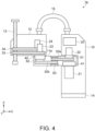
FIG. 4 is a side view showing internal configuration of a horizontal articulated robot according to a second embodiment. -
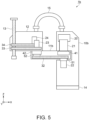
FIG. 5 is a side view showing internal configuration of a horizontal articulated robot according to a third embodiment. -
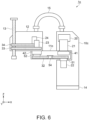
FIG. 6 is a side view showing internal configuration of a horizontal articulated robot according to a fourth embodiment. -
FIG. 7 is a plan view showing internal configuration of a first arm of the horizontal articulated robot according to the fourth embodiment. -
FIG. 8 is a side view showing internal configuration of a horizontal articulated robot according to ta fifth embodiment. - A horizontal articulated
robot 1 according to a first embodiment will be described with reference toFIGS. 1 and2 . For convenience of description, an X-axis, a Y-axis, and a Z-axis are illustrated in the following drawings as three axes orthogonal to each other. A direction along the X axis is referred to as an "X direction", a direction along the Y axis is referred to as a "Y direction", and a direction along the Z axis is referred to as a "Z direction". In addition, the arrow tip end side of each axis is also referred to as a "plus side", and the side opposite to the arrow is also referred to as a "minus side". Further, the positive side in the Z direction is also referred to as "above" and the negative side in the Z direction is also referred to as "below". - The horizontal articulated
robot 1 includes, as shown inFIGS. 1 and2 , abase 10, afirst arm 11 coupled to thebase 10 and configured to pivot about a first pivot axis F1, asecond arm 12 coupled to thefirst arm 11 and configured to pivot about the second pivot axis F2, which is parallel to the first pivot axis F1, athird arm 13 that rotates around a third pivot axis F3, which is parallel to the second pivot axis F2, and that drives in a direction along the third pivot axis F3, afirst motor 21 configured to drive thefirst arm 11, asecond motor 22 configured to drive thesecond arm 12, athird motor 23 configured to drive thethird arm 13, and afourth motor 24 configured to drive thethird arm 13 in the vertical direction. - The horizontal articulated
robot 1 is fixed to a floor or the like via amounting base 14 coupled to thebase 10. The first pivot axis F1, the second pivot axis F2, and the third pivot axis F3 are orthogonal to the XY plane, which is a horizontal plane. The third pivot axis F3 coincides with the central axis of thethird arm 13. - The
base 10 is coupled to thefirst arm 11, and includes afirst motor 21 that drives thefirst arm 11, asecond motor 22 that drives thesecond arm 12, and acontrol section 20 that controls thefirst arm 11, thesecond arm 12, and aspindle arm 13. Thefirst motor 21 and thesecond motor 22 are disposed separated from each other above and below thefirst arm 11, and in the present embodiment, thefirst motor 21 is disposed below thefirst arm 11. Therefore, a heavy motor having a large output can be used as thefirst motor 21 at the lower part of thebase 10, and the horizontal articulatedrobot 1 can be stably fixed with a good balance. - As shown in
FIG. 2 , thefirst arm 11 is coupled to thebase 10 and is pivoted around the first pivot axis F1 by thefirst motor 21, which is disposed in thebase 10. Afirst decelerator 41 coupled to thefirst motor 21 is provided in thefirst arm 11. Rotation of thefirst motor 21 is input to thefirst decelerator 41, and thefirst decelerator 41 has a function of outputting torque corresponding to a speed reduction ratio while reducing the speed of the input rotation using a plurality of gears having different numbers of teeth. That is, the output is amplified by reducing the rotational speed of the input. The rotational axis of thefirst motor 21 and the rotational axis of thefirst decelerator 41 coincide with the first pivot axis F1, and thefirst arm 11 pivots around the first pivot axis F1. Apulley 51, abelt 32, apulley 52, and asecond decelerator 42 for transmitting the driving force of thesecond motor 22 to thesecond arm 12 are disposed inside thefirst arm 11. - The
second arm 12 is coupled to thefirst arm 11, and is pivoted around the second pivot axis F2, which is parallel to the first pivot axis F1, by thesecond motor 22, which is disposed in thebase 10. An axis M2, which is the rotational axis of thesecond motor 22, which is arranged in thebase 10, coincides with the first pivot axis F1 of thefirst arm 11. The driving force of thesecond motor 22 is transmitted to thesecond arm 12 via thebelt 32, which is provided in the first arm. More specifically, the driving force of thesecond motor 22 is transmitted to thebelt 32 by rotation of thepulley 51 coupled to thesecond motor 22 and is transmitted to thesecond arm 12 by rotation of thepulley 52 connected to thesecond arm 12. Since the axis M2, which is the rotational axis of thesecond motor 22, coincides with the first pivot axis F1 of thefirst arm 11, it is possible to prevent the area occupied by thebase 10 or the horizontal articulatedrobot 1 from increasing. - Note that in the present embodiment, a
second decelerator 42 is provided between thesecond arm 12 and thepulley 52 and thesecond decelerator 42 decelerates rotation of thesecond motor 22 and transmits the driving force to thesecond arm 12. Rotation of thesecond motor 22 is input to thesecond decelerator 42, and thesecond decelerator 42 has a function of outputting torque corresponding to a speed reduction ratio while reducing the speed of the input rotation using a plurality of gears having different numbers of teeth. That is, the output is amplified by reducing the rotational speed of the input. Since thesecond motor 22, which drives thesecond arm 12, is disposed in thebase 10, it is possible to reduce the weight of thesecond arm 12 and to achieve a reduction in inertia. As thesecond motor 22, it is possible to use a motor having a large output capable of achieving a high speed. - The
third arm 13 is coupled to thesecond arm 12, is rotated around the third pivot axis F2, which is parallel to the second pivot axis F2, by thethird motor 23 and abelt 33 provided in thesecond arm 12, and is vertically driven in the Z direction, which are the directions of arrows G along the third pivot axis F3, by thefourth motor 24 and abelt 34 provided in thesecond arm 12. Thethird arm 13 is controlled by thecontrol section 20 via acontrol cable 15 provided between thebase 10 and thesecond arm 12, and is pivoted and vertically driven. Note that by attaching a clamping device or a suction device to the end portion of thethird arm 13 on the minus side of the Z direction, it is possible to clamp or suction an object and transfer the object to a predetermined place. - As described above, in the horizontal articulated
robot 1 of the present embodiment, the weight of thesecond arm 12 can be reduced because thesecond motor 22 for driving thesecond arm 12 is disposed in thebase 10. Therefore, the weight of the arm portion is reduced and the inertia associated with the driving of the arm can be reduced. - Note that although the configuration in which the
second decelerator 42 is provided in thefirst arm 11 was indicated, a configuration may be adopted in which, for example, as in the horizontal articulatedrobot 1x shown inFIG. 3 , thesecond decelerator 42 is provided between thefirst arm 11 and thesecond arm 12. In this case, thesecond decelerator 42 may be exposed to the outside, or thesecond decelerator 42 may be covered by the case of thesecond arm 12. - Next, a horizontal articulated
robot 1a according to a second embodiment will be described with reference toFIG. 4 . - Compared to the horizontal articulated
robot 1 of the first embodiment, the horizontal articulatedrobot 1a of the present embodiment is the same as the horizontal articulatedrobot 1 of the first embodiment except that the configuration of thefirst arm 11a is different. Note that the differences from the first embodiment described above will be mainly described, and similar items will be designated by the same reference numerals and description thereof will be omitted. - In the horizontal articulated
robot 1a, as shown inFIG. 4 , apulley 53 arranged between thepulley 51 and thepulley 52, abelt 32a in contact with thepulley 51 and thepulley 53, and abelt 32b in contact with thepulley 52 and thepulley 53 are arranged in thefirst arm 11a, which is coupled to thebase 10. Therefore, the driving force of thesecond motor 22 is transmitted to thesecond arm 12 via thepulleys belts - Since the
first arm 11a is configured such that thebelt 32a is disposed between thesecond motor 22 and thebelt 32b, thesecond decelerator 42 can be disposed between thesecond arm 12 and thebelt 32b. Therefore, it is possible to make thefirst arm 11a thin in the Z direction, and to reduce the weight of thefirst arm 11a and the height of the horizontal articulatedrobot 1a. - With such a configuration, it is possible to reduce the height of the horizontal articulated
robot 1a, in addition to the effects obtained in the first embodiment. - Next, a horizontal articulated
robot 1b according to a third embodiment will be described with reference toFIG. 5 . - Compared to the horizontal articulated
robot 1 of the first embodiment, the horizontal articulatedrobot 1b of the present embodiment is the same as the horizontal articulatedrobot 1 of the first embodiment except that the arrangement configuration of thefirst motor 21 and thesecond motor 22 in thebase 10b and the configuration in thefirst arm 11b are different. Note that the differences from the first embodiment described above will be mainly described, and similar items will be designated by the same reference numerals and description thereof will be omitted. - In the horizontal articulated
robot 1b, as shown inFIG. 5 , thefirst motor 21 and thesecond motor 22 in thebase 10b are disposed separated from each other above and below thefirst arm 11b, thefirst motor 21 is disposed above thefirst arm 11b, and thesecond motor 22 is disposed below thefirst arm 11b. By disposing thesecond motor 22 below thefirst arm 11b, thesecond decelerator 42 can be disposed between thebelt 32, which transmits the driving force of thesecond motor 22 in thefirst arm 11b, and thesecond arm 12. Therefore, it is possible to make thefirst arm 11b thin in the Z direction and to reduce the weight of thefirst arm 11b and the height of the horizontal articulatedrobot 1b. - With such a configuration, it is possible to reduce the height of the horizontal articulated
robot 1b, in addition to the effects obtained in the first embodiment. - Next, a horizontal articulated
robot 1c according to a fourth embodiment will be described with reference toFIGS. 6 and7 . - Compared to the horizontal articulated
robot 1 of the first embodiment, the horizontal articulatedrobot 1c of the present embodiment is the same as the horizontal articulatedrobot 1 of the first embodiment except that the arrangement configuration of thefirst motor 21 and thesecond motor 22 in thebase 10c and the configuration in thefirst arm 11c are different. Note that the differences from the first embodiment described above will be mainly described, and similar items will be designated by the same reference numerals and description thereof will be omitted. - In the horizontal articulated
robot 1c, as shown inFIGS. 6 and7 , thefirst motor 21 in thebase 10c is disposed above thefirst arm 11c and thesecond motor 22 in thebase 10c is disposed below thefirst arm 11c. By disposing thesecond motor 22 below thefirst arm 11c, thesecond decelerator 42, which reduces the speed of the rotation of thesecond arm 12, can be disposed between thebelt 32, which transmits the driving force of thesecond motor 22 in thefirst arm 11c, and thesecond arm 12. - Further, a
pulley 54 for adjusting the tension of thebelt 32 is disposed in thefirst arm 11c in between thepulley 51 and thepulley 52. Therefore, it is possible to control a decrease in the frictional force between thepulley 51 andpulley 52 and thebelt 32 and it is possible to more efficiently transmit the driving force of thesecond motor 22 to thesecond arm 12. - With such a configuration, in addition to the effects obtained in the first embodiment, the height of the horizontal articulated
robot 1c can be reduced and also the driving force of thesecond motor 22 can be more efficiently transmitted to thesecond arm 12. - Next, a horizontal articulated
robot 1d according to a fifth embodiment will be described with reference toFIG. 8 . - Compared to the horizontal articulated
robot 1 of the first embodiment, the horizontal articulatedrobot 1d of the present embodiment is the same as the horizontal articulatedrobot 1 of the first embodiment except that the arrangement position of thesecond decelerator 42 is different. Note that the differences from the first embodiment described above will be mainly described, and similar items will be designated by the same reference numerals and description thereof will be omitted. - In the horizontal articulated
robot 1d, as shown inFIG. 8 , thesecond decelerator 42, which decelerates the rotation of thesecond arm 12, is disposed in thebase 10d. Therefore, the weight of the arm can be further reduced and inertia associated with drive of the arm can be further reduced. - With such a configuration, it is possible to further improve the effects obtained in the first embodiment.
- In the above embodiments, configurations in which the
first motor 21 and thesecond motor 22 are separately disposed above and below thefirst arm 11 in thebase 10 was described, but the disclosure is not limited thereto. For example, both thefirst motor 21 and thesecond motor 22 may be provided below thefirst arm 11 in thebase 10. Further, both thefirst motor 21 and thesecond motor 22 may be provided above thefirst arm 11 in thebase 10. - Configurations were described as having the
first decelerator 41 and thesecond decelerator 42, but the present disclosure is not limited thereto. For example, in a case where a motor having a large output torque such as a so-called direct drive motor can be adopted as thefirst motor 21 or thesecond motor 22, a structure in which thefirst motor 21 directly drives thefirst arm 11 or a structure in which thesecond motor 22 directly drives thesecond arm 12 may be adopted. - Configurations in which the
control section 20 is disposed in thebase 10 were described, but the present disclosure is not limited thereto. For example, a configuration may be adopted in which a control device is disposed outside thebase 10 and is connected by a cable.
Claims (7)
- A horizontal articulated robot comprising:a base;a first arm coupled to the base and configured to pivot about a first pivot axis;a second arm coupled to the first arm and configured to pivot about a second pivot axis, which is parallel to the first pivot axis;a first motor configured to drive the first arm; anda second motor configured to drive the second arm, whereinthe first motor and the second motor are disposed in the base, and a driving force of the second motor is transmitted to the second arm via a belt provided inside the first arm.
- The horizontal articulated robot according to claim 1, wherein
an axis of the second motor coincides with the first pivot axis. - The horizontal articulated robot according to claim 1, wherein
the first motor and the second motor are disposed in the base separated from each other above and below the first arm. - The horizontal articulated robot according to claim 3, wherein
the first motor is disposed below the first arm. - The horizontal articulated robot according to claim 3, wherein
the second motor is disposed below the first arm. - The horizontal articulated robot according to claim 1, further comprising:
a pulley that is provided inside the first arm and that adjusts tension of the belt. - The horizontal articulated robot according to claim 1, further comprising:
a decelerator that decelerates rotation of the second arm and that transmits the driving force to the second arm, the decelerator being disposed in the base.
Applications Claiming Priority (1)
| Application Number | Priority Date | Filing Date | Title |
|---|---|---|---|
| JP2022155983A JP2024049638A (en) | 2022-09-29 | 2022-09-29 | Horizontal articulated robot |
Publications (1)
| Publication Number | Publication Date |
|---|---|
| EP4344832A1 true EP4344832A1 (en) | 2024-04-03 |
Family
ID=88207670
Family Applications (1)
| Application Number | Title | Priority Date | Filing Date |
|---|---|---|---|
| EP23200199.0A Pending EP4344832A1 (en) | 2022-09-29 | 2023-09-27 | Horizontal articulated robot |
Country Status (4)
| Country | Link |
|---|---|
| US (1) | US20240109182A1 (en) |
| EP (1) | EP4344832A1 (en) |
| JP (1) | JP2024049638A (en) |
| CN (1) | CN117773896A (en) |
Citations (8)
| Publication number | Priority date | Publication date | Assignee | Title |
|---|---|---|---|---|
| JPH07246580A (en) * | 1994-03-14 | 1995-09-26 | Sony Corp | Articulated robot |
| JP2002164402A (en) * | 2000-11-24 | 2002-06-07 | Meidensha Corp | Substrate transfer robot |
| JP2005125489A (en) | 2003-10-23 | 2005-05-19 | Bosch Rexroth Ag | Scalar type robot |
| US20100095800A1 (en) * | 2008-10-17 | 2010-04-22 | Staubli Faverges | Articulated structure for a multi-axis robot, and a robot including such a structure |
| US9296114B2 (en) * | 2012-03-02 | 2016-03-29 | Staubli Faverges | Articulated structure of a multiple-axis robot and robot comprising such a structure |
| DE102016222255B3 (en) * | 2016-11-14 | 2018-04-12 | Kuka Roboter Gmbh | Robotic arm, mobile robot and logistics system |
| CN112248028A (en) * | 2020-09-10 | 2021-01-22 | 珠海格力电器股份有限公司 | Articulated arm structure and robot |
| JP2022155983A (en) | 2021-03-31 | 2022-10-14 | ミネベアミツミ株式会社 | motor |
Family Cites Families (12)
| Publication number | Priority date | Publication date | Assignee | Title |
|---|---|---|---|---|
| FR2539346B1 (en) * | 1983-01-18 | 1990-12-07 | Mitsubishi Electric Corp | ARTICULATED AUTOMATIC MANIPULATOR DEVICE, PARTICULARLY FOR ARC WELDING |
| JPS6036192U (en) * | 1983-08-18 | 1985-03-12 | シルバー精工株式会社 | industrial robot |
| JPH0630853B2 (en) * | 1985-09-10 | 1994-04-27 | 株式会社三協精機製作所 | Rotating arm joint structure |
| JPH0630852B2 (en) * | 1985-09-10 | 1994-04-27 | 株式会社三協精機製作所 | Articulated robot |
| US5064340A (en) * | 1989-01-20 | 1991-11-12 | Genmark Automation | Precision arm mechanism |
| US5634377A (en) * | 1994-03-09 | 1997-06-03 | Sony Corporation | Articulated robot |
| CN102049773B (en) * | 2009-10-29 | 2013-08-28 | 鸿富锦精密工业(深圳)有限公司 | Planar articulated robot |
| JP5304601B2 (en) * | 2009-11-10 | 2013-10-02 | 株式会社安川電機 | Arm mechanism and vacuum robot equipped with the same |
| JP2011119556A (en) * | 2009-12-07 | 2011-06-16 | Yaskawa Electric Corp | Horizontal multi-joint robot and transportation apparatus including the same |
| JP2020163548A (en) * | 2019-03-29 | 2020-10-08 | セイコーエプソン株式会社 | Horizontal articulated robots and robot systems |
| JP7293844B2 (en) * | 2019-04-25 | 2023-06-20 | セイコーエプソン株式会社 | robot |
| TWI891941B (en) * | 2020-11-26 | 2025-08-01 | 日商發那科股份有限公司 | Tension estimation device, life assessment device and robotic system |
-
2022
- 2022-09-29 JP JP2022155983A patent/JP2024049638A/en active Pending
-
2023
- 2023-09-27 EP EP23200199.0A patent/EP4344832A1/en active Pending
- 2023-09-27 US US18/373,307 patent/US20240109182A1/en active Pending
- 2023-09-27 CN CN202311270309.8A patent/CN117773896A/en active Pending
Patent Citations (8)
| Publication number | Priority date | Publication date | Assignee | Title |
|---|---|---|---|---|
| JPH07246580A (en) * | 1994-03-14 | 1995-09-26 | Sony Corp | Articulated robot |
| JP2002164402A (en) * | 2000-11-24 | 2002-06-07 | Meidensha Corp | Substrate transfer robot |
| JP2005125489A (en) | 2003-10-23 | 2005-05-19 | Bosch Rexroth Ag | Scalar type robot |
| US20100095800A1 (en) * | 2008-10-17 | 2010-04-22 | Staubli Faverges | Articulated structure for a multi-axis robot, and a robot including such a structure |
| US9296114B2 (en) * | 2012-03-02 | 2016-03-29 | Staubli Faverges | Articulated structure of a multiple-axis robot and robot comprising such a structure |
| DE102016222255B3 (en) * | 2016-11-14 | 2018-04-12 | Kuka Roboter Gmbh | Robotic arm, mobile robot and logistics system |
| CN112248028A (en) * | 2020-09-10 | 2021-01-22 | 珠海格力电器股份有限公司 | Articulated arm structure and robot |
| JP2022155983A (en) | 2021-03-31 | 2022-10-14 | ミネベアミツミ株式会社 | motor |
Also Published As
| Publication number | Publication date |
|---|---|
| JP2024049638A (en) | 2024-04-10 |
| CN117773896A (en) | 2024-03-29 |
| US20240109182A1 (en) | 2024-04-04 |
Similar Documents
| Publication | Publication Date | Title |
|---|---|---|
| US6593718B1 (en) | Horizontal multi-joint industrial robot | |
| US8434387B2 (en) | Industrial robot | |
| JP3413730B2 (en) | Horizontal articulated robot | |
| KR890000737B1 (en) | Industrial robot employment direct drive operation | |
| WO1989002810A1 (en) | Statically-balanced direct-drive robot arm | |
| US8381609B2 (en) | Articulated structure for a multi-axis robot, and a robot including such a structure | |
| JPH01183382A (en) | Machine drive mechanism | |
| US6684128B1 (en) | Robot and method of controlling the robot | |
| CN114800461B (en) | Driving mechanism and robot | |
| US20150013491A1 (en) | Wrist structure unit of industrial robot | |
| US20240109182A1 (en) | Horizontal articulated robot | |
| US20250128404A1 (en) | Robot | |
| CN116175531B (en) | robotic arms and robot systems | |
| US12007002B2 (en) | Power transmission device | |
| JP2637148B2 (en) | SCARA robot | |
| JP4521746B2 (en) | Link-type workpiece transfer robot | |
| US20250296223A1 (en) | Vertical articulated robot | |
| US20260109032A1 (en) | Transfer robot | |
| JPH01228792A (en) | Straight rotation unit | |
| JPS61214984A (en) | Industrial robot | |
| KR100487152B1 (en) | Multi-articulated robot | |
| JPH0643039B2 (en) | Arm drive device for articulated robot | |
| JPS61152381A (en) | Industrial robot | |
| JPH0557662A (en) | Industrial robots | |
| JPS61214985A (en) | Industrial robot |
Legal Events
| Date | Code | Title | Description |
|---|---|---|---|
| PUAI | Public reference made under article 153(3) epc to a published international application that has entered the european phase |
Free format text: ORIGINAL CODE: 0009012 |
|
| STAA | Information on the status of an ep patent application or granted ep patent |
Free format text: STATUS: THE APPLICATION HAS BEEN PUBLISHED |
|
| AK | Designated contracting states |
Kind code of ref document: A1 Designated state(s): AL AT BE BG CH CY CZ DE DK EE ES FI FR GB GR HR HU IE IS IT LI LT LU LV MC ME MK MT NL NO PL PT RO RS SE SI SK SM TR |
|
| STAA | Information on the status of an ep patent application or granted ep patent |
Free format text: STATUS: REQUEST FOR EXAMINATION WAS MADE |
|
| 17P | Request for examination filed |
Effective date: 20241001 |
|
| RBV | Designated contracting states (corrected) |
Designated state(s): AL AT BE BG CH CY CZ DE DK EE ES FI FR GB GR HR HU IE IS IT LI LT LU LV MC ME MK MT NL NO PL PT RO RS SE SI SK SM TR |