EP4344823A1 - Grinding segment and cup wheel with grinding segments - Google Patents
Grinding segment and cup wheel with grinding segments Download PDFInfo
- Publication number
- EP4344823A1 EP4344823A1 EP22198652.4A EP22198652A EP4344823A1 EP 4344823 A1 EP4344823 A1 EP 4344823A1 EP 22198652 A EP22198652 A EP 22198652A EP 4344823 A1 EP4344823 A1 EP 4344823A1
- Authority
- EP
- European Patent Office
- Prior art keywords
- grinding
- superabrasive particles
- bond material
- segment
- height
- Prior art date
- Legal status (The legal status is an assumption and is not a legal conclusion. Google has not performed a legal analysis and makes no representation as to the accuracy of the status listed.)
- Pending
Links
- 238000000227 grinding Methods 0.000 title claims abstract description 247
- 239000002245 particle Substances 0.000 claims abstract description 221
- 239000000463 material Substances 0.000 claims abstract description 95
- 230000007704 transition Effects 0.000 claims description 7
- 238000010276 construction Methods 0.000 description 9
- 238000003466 welding Methods 0.000 description 7
- 238000007731 hot pressing Methods 0.000 description 6
- 238000005245 sintering Methods 0.000 description 6
- 239000000843 powder Substances 0.000 description 4
- 238000011069 regeneration method Methods 0.000 description 4
- 238000005219 brazing Methods 0.000 description 3
- 239000004567 concrete Substances 0.000 description 3
- 230000003247 decreasing effect Effects 0.000 description 3
- 229910003460 diamond Inorganic materials 0.000 description 3
- 239000010432 diamond Substances 0.000 description 3
- 239000004579 marble Substances 0.000 description 3
- 238000000034 method Methods 0.000 description 3
- 238000002156 mixing Methods 0.000 description 3
- 238000004663 powder metallurgy Methods 0.000 description 3
- 238000005476 soldering Methods 0.000 description 3
- 239000004575 stone Substances 0.000 description 3
- 229910052582 BN Inorganic materials 0.000 description 2
- PZNSFCLAULLKQX-UHFFFAOYSA-N Boron nitride Chemical compound N#B PZNSFCLAULLKQX-UHFFFAOYSA-N 0.000 description 2
- 230000008901 benefit Effects 0.000 description 2
- 230000008878 coupling Effects 0.000 description 2
- 238000010168 coupling process Methods 0.000 description 2
- 238000005859 coupling reaction Methods 0.000 description 2
- 238000009826 distribution Methods 0.000 description 2
- 238000005516 engineering process Methods 0.000 description 2
- 239000010438 granite Substances 0.000 description 2
- 238000003754 machining Methods 0.000 description 2
- 238000004519 manufacturing process Methods 0.000 description 2
- 239000000203 mixture Substances 0.000 description 2
- 230000008569 process Effects 0.000 description 2
- 239000000126 substance Substances 0.000 description 2
- 239000000654 additive Substances 0.000 description 1
- 230000015556 catabolic process Effects 0.000 description 1
- 230000006835 compression Effects 0.000 description 1
- 238000007906 compression Methods 0.000 description 1
- 238000005520 cutting process Methods 0.000 description 1
- 230000002950 deficient Effects 0.000 description 1
- 238000006731 degradation reaction Methods 0.000 description 1
- 238000005553 drilling Methods 0.000 description 1
- 239000012634 fragment Substances 0.000 description 1
- 230000020169 heat generation Effects 0.000 description 1
- 230000006872 improvement Effects 0.000 description 1
- 230000001788 irregular Effects 0.000 description 1
- 238000009828 non-uniform distribution Methods 0.000 description 1
- 238000004080 punching Methods 0.000 description 1
Images


Classifications
-
- B—PERFORMING OPERATIONS; TRANSPORTING
- B24—GRINDING; POLISHING
- B24D—TOOLS FOR GRINDING, BUFFING OR SHARPENING
- B24D99/00—Subject matter not provided for in other groups of this subclass
- B24D99/005—Segments of abrasive wheels
-
- B—PERFORMING OPERATIONS; TRANSPORTING
- B24—GRINDING; POLISHING
- B24D—TOOLS FOR GRINDING, BUFFING OR SHARPENING
- B24D18/00—Manufacture of grinding tools or other grinding devices, e.g. wheels, not otherwise provided for
- B24D18/0009—Manufacture of grinding tools or other grinding devices, e.g. wheels, not otherwise provided for using moulds or presses
-
- B—PERFORMING OPERATIONS; TRANSPORTING
- B24—GRINDING; POLISHING
- B24D—TOOLS FOR GRINDING, BUFFING OR SHARPENING
- B24D18/00—Manufacture of grinding tools or other grinding devices, e.g. wheels, not otherwise provided for
- B24D18/0045—Manufacture of grinding tools or other grinding devices, e.g. wheels, not otherwise provided for by stacking sheets of abrasive material
-
- B—PERFORMING OPERATIONS; TRANSPORTING
- B24—GRINDING; POLISHING
- B24D—TOOLS FOR GRINDING, BUFFING OR SHARPENING
- B24D7/00—Bonded abrasive wheels, or wheels with inserted abrasive blocks, designed for acting otherwise than only by their periphery, e.g. by the front face; Bushings or mountings therefor
- B24D7/06—Bonded abrasive wheels, or wheels with inserted abrasive blocks, designed for acting otherwise than only by their periphery, e.g. by the front face; Bushings or mountings therefor with inserted abrasive blocks, e.g. segmental
- B24D7/063—Bonded abrasive wheels, or wheels with inserted abrasive blocks, designed for acting otherwise than only by their periphery, e.g. by the front face; Bushings or mountings therefor with inserted abrasive blocks, e.g. segmental with segments embedded in a matrix which is rubbed away during the grinding process
Definitions
- the present invention relates to tool bits for grinding materials such as concrete, granite, stone, marble or the like and grinding segments to be connected on such tool bits for grinding, and more particularly to grinding segments in which superabrasive particles are distributed according to a predetermined particle design in a bond material and by which the grinding performance and service life of the tool bit can be improved.
- Tool bits for grinding are composed of a disc-shaped or cup-shaped basic body, a plurality of grinding segments connected to the basic body, and a plurality of suction holes arranged in the basic body and configured to discharge removed particles.
- the basic body includes an outer circumferential section, an inner section configured to connect the tool bit to a motorized power tool, and a transition section arranged between the circumferential section and inner section.
- the grinding segments are connected to the basic body by brazing, soldering, welding or the like, and the suction holes are arranged in at least one of the circumferential section and the transition section of the basic body.
- Typical grinding segments are manufactured by mixing superabrasive particles with a suitable bond material (e.g., powder). The mixture is compressed in a mold to form a green body, which is then consolidated by free-form sintering, hot-pressing, or infiltrating to form a single grinding segment. Finally, the grinding segments are connected by brazing, soldering, welding or the like to the basic body to form the final tool bit for grinding.
- a suitable bond material e.g., powder
- the superabrasive particles During the process of mixing the superabrasive particles with the bond material, the superabrasive particles have a much larger size compared to the particles of the bond material and so tend to freely flow, so that under the condition of a finite overall blending ratio of the superabrasive particles to the bond material, the superabrasive particles may be highly concentrated in certain regions or very deficient below the average concentration in other regions to cause irregular or non-uniform distribution of the superabrasive particles within the grinding segments.
- the grinding wheel rotates at a certain speed and removes surface parts of stone, concrete, marble, or the like with the torque originating from the motorized power tool, and during the course, the superabrasive particles on the grinding segments experience severe load due to the reactive force of the object in the form of friction, with the result that the superabrasive particles can be worn out, loosened, or even broken.
- the load of friction imposed on an individual superabrasive particle would be decreased.
- the superabrasive particles would be in active working and so dulled in the sharp grinding segments or can be subjected to a degradation together with the bond material due to an abrupt frictional heat generation, however the self-regeneration remains at a low level, so that deformation or unevenness on the surface of the grinding wheel can result.
- the superabrasive particles in the sections of the grinding segments where the concentration of the superabrasive particles is relatively low, are subjected to larger load of friction or impact per unit particle and therefore the superabrasive particles are easily broken, constituting a cause of decreasing the service life of the tool bit.
- the present invention was created to resolve the problems with the prior art as described above, and the object of the present invention is to provide a grinding segment and a tool bit for grinding equipped with the grinding segments, which allow precise grinding operation thanks to the defined distribution of the superabrasive particles, and which make possible the marked improvement in the grinding performance and/or in the service life of tool bits for grinding.
- each of the M layers of the bond material has at least one of a structured lower surface and a structured upper surface, wherein the structured lower surfaces and/or structured upper surfaces of the M layers have a first structure that corresponds to the predetermined particle design of the superabrasive particles.
- the grinding segment is fabricated via powder metallurgy, in which a green body is build up layer by layer and then the green body is further processed by free-form sintering, by hot-pressing and/or by infiltrating to form the final grinding segment.
- the grinding segment includes a bond material that is at least one of free-form sintered, hot pressed and infiltrated and a plurality of superabrasive particles being arranged according to a predetermined particle design and bonded in the bond material.
- the grinding segment according to the present invention is composed of at least two layers of the bond material and of at least one pattern of the superabrasive particles, the layers and patterns being stacked in the height direction of the grinding segment.
- Each of the layers of the bond material has a lower surface and an upper surface and at least one of the lower and upper surfaces of each layer is a structured surface having a first structure that corresponds to the predetermined particle design of the superabrasive particles.
- the structured lower and/or upper surfaces of each layer enable that the superabrasive particles of a pattern can be arranged on different height levels with height differences between adjacent height levels.
- the height levels will preferably be selected such that the superabrasive particles of a following height level will be opened at a certain wearout of the superabrasive particles of the previous height level. During grinding with the tool bit for grinding, the active superabrasive particles wear out and their size in the height direction is reduced.
- the M layers of the bond material include at least a first layer having a first lower surface and a first upper surface, wherein the first upper surface has the first structure, and the first lower surface is non-structured.
- the first layer has a non-structured first lower surface and a structured first upper surface.
- the non-structured first lower surface may be used as front side of the grinding segment, the front side being opposite of a back side of the grinding segment, and the grinding segment being connected via the back side to the basic body of a tool bit.
- the M layers of the bond material include at least a first layer having a first lower surface and a first upper surface, wherein the first upper surface has the first structure, and the first lower surface has a second structure that is different from the first structure of the first upper surface.
- the first layer has a structured first upper surface and a structured first lower surface, the first structure of the first upper surface being different from the second structure of the first lower surface.
- the structured first lower surface may be used as front side of the grinding segment, the front side being opposite of a back side of the grinding segment, and the grinding segment being connected via the back side to a basic body of a tool bit.
- a structured first lower surface as front side may have the advantage that the surface area of the front side that is in contact with the basic body of the tool bit is reduced.
- a decreased surface area may be preferred.
- the M layers of the bond material include at least a M-th layer having a M-th lower surface and a M-th upper surface, wherein the M-th lower surface and the M-th upper surface have the first structure.
- the structured M-th upper surface may be used as back side of the grinding segment, the grinding segment being connected via the back side to a basic body of a tool bit.
- the bond material is at least one of a first bond material and a second bond material, the second bond material being different from the first bond material.
- the grinding segment is composed of at least two layers of the bond material and of at least two patterns of the superabrasive particles.
- the superabrasive particles are arranged according to a predetermined particle design and fixed by the bond material that is at least one of free-form sintered and hot-pressed.
- the first bond material may be used to fix the superabrasive particles and the second bond material may be used in a contact area with the connection face to allow welding of the grinding segment.
- the layers of bond material may comprise a first bond material and second bond material
- the first bond material may be applied to inner regions of the layers to fix the superabrasive particles
- the second bond material may be applied to outer regions of the layers to strengthen the side surfaces of the grinding segment.
- each pattern of superabrasive particles includes at least two groups of K, K ⁇ 2 lines of the superabrasive particles, the superabrasive particles of adjacent lines being arranged on different height levels in the height direction.
- the grinding segment is composed of at least one pattern of the superabrasive particles, the patterns being stacked in the height direction.
- the superabrasive particles are arranged according to the predetermined particle design that includes two or more groups of at least two lines of the superabrasive particles.
- the number of groups is preferably adapted to the abrasiveness of the workpiece to be grinded and/or the expected lifetime of the grinding segment.
- the superabrasive particles are arranged on a similar height level in the height direction, and the superabrasive particles of adjacent lines are arranged on different height levels.
- the number of lines and the height levels of the different types of lines may be selected such that the superabrasive particles of the next type of lines are opened before the superabrasive particles positioned just above have been worn out at a certain percentage, so that self-regeneration of the superabrasive particles may be repeated for the service time of the grinding segment.
- the height levels of the last type of lines of a previous pattern and the first type of lines of a following pattern may be selected such that the superabrasive particles of the next type of lines are opened before the superabrasive particles of the last line positioned just above have been worn out at a certain percentage, so that self-regeneration of the superabrasive particles may be repeated for the service time of the grinding segment.
- each of the at least two groups comprises a first line of superabrasive particles, a second line of superabrasive particles, and a third line of superabrasive particles, wherein the first lines being arranged on a first height level, the second lines being arranged on a second height level, and the third lines being arranged on a third height level, and wherein the first height level, second height level and third height level being different from each other in the height direction.
- the superabrasive particles are arranged according to the predetermined particle design that includes two or more groups of a first line, a second line, and a third line of superabrasive particles, wherein the superabrasive particles of the first, second, and third line are arranged on the first, second, and third height level.
- the height differences between the first and second height level and between the second and third height level are substantially equal.
- the lines of superabrasive particles of each group define a linear arrangement and the superabrasive particles of the adjacent lines will become active one after the other.
- the height differences between the first and second height level and between the second and third height level are different from each other.
- the lines of superabrasive particles of each group define a non-linear arrangement that helps in retaining a more uniform wearout at the edges of the grinding segment and keeping the tool bit grinding for the service life.
- each of the at least two groups further comprises a fourth line of superabrasive particles, wherein the fourth lines being arranged on a fourth height level, and wherein the fourth height level is different from the first height level, second height level and third height level in the height direction.
- the number of lines of each group and the height differences between the lines may be selected such that the superabrasive particles of a line will be opened at a certain wearout of the superabrasive particles of the previous line.
- each of the at least two groups may further comprise a fifth line of superabrasive particles, wherein the fifth lines being arranged on a fifth height level, and wherein the fifth height level is different from the first height level, second height level, third height level, and fourth height level in the height direction.
- the number of lines of each group and the height differences between the lines may be selected such that the superabrasive particles of a line will be opened at a certain wearout of the superabrasive particles of the previous line.
- a tool bit for grinding comprising a basic body including an inner section configured to connect the tool bit to a power tool, and a circumferential section with a connection surface, and two or more grinding segments according to the invention, wherein the grinding segments are connected to the connection surface.
- the tool bit comprises a disc-shaped or cup-shaped basic body and two or more grinding segments.
- the grinding segments comprise a front side and a back side opposite of the front side, and the grinding segments being connected via the back side to the basic body.
- a tool bit according to the invention may have a similar performance over the lifetime since the superabrasive particles are distributed in the grinding segment according to the predetermined particle design.
- the grinding segments are connected to the connection surface with the upper surface of the M-th layer of the bond material.
- the grinding segments are composed of M, M ⁇ 2 layers of the bond material and of N, N ⁇ 1 patterns of the superabrasive particles, the layers and patterns being stacked in the height direction of the grinding segment.
- Each of the M layers of the bond material has at least one of a structured lower surface and a structured upper surface.
- the tool bit further comprises a plurality of suction holes being arranged in at least one of the circumferential section or a transition section that is arranged between the circumferential section and inner section.
- the phrase "at least one" in reference to a list of one or more elements should be understood to mean at least one element selected from any one or more of the elements in the list of elements, but not necessarily including at least one of each and every element specifically listed within the list of elements and not excluding any combinations of elements in the list of elements.
- This definition also allows that elements may optionally be present other than the elements specifically identified within the list of elements to which the phrase "at least one" refers, whether related or unrelated to those elements specifically identified.
- the term “segment” means a piece or fragment substantially in the form of a sector, particularly used for the purpose of cutting, grinding, sawing, drilling or the like as well.
- the term “bond material” refers to a material to which superabrasive particles may be bonded. Bond materials typically consist of a base powder, which is combined with compression auxiliaries and additives which serve to optimize the properties of the base powder material with regard to the strength and wear rate of the segments.
- the base powder may consist of one base material or be composed of several base materials.
- superabrasive particles refer to particles of either natural or synthetic diamond, super hard crystalline, or polycrystalline substance, or mixtures of substances and include but are not limited to diamond, polycrystalline diamond (PCD), cubic boron nitride (CBN), and polycrystalline cubic boron nitride (PCBN).
- predetermined particle design refers to a non-random particle design of the superabrasive particles that is identified prior to construction of a tool bit, and which individually places or locates each superabrasive particle in a defined relationship with the other superabrasive particles, and with the configuration of the tool bit.
- FIGS. 1A , B show a tool bit 10 for grinding according to the present invention.
- the tool bit 10 is formed as cup-shaped grinding wheel and comprises a cup-shaped basic body 11, a plurality of grinding segments 12 according to the present invention, and a plurality of suction holes 13.
- the grinding segments 12 are connected via a back side 14 to the basic body 11.
- FIG. 1A shows the grinding wheel 10 in a view on a front side 15 opposite to the back side 14 of the grinding segments 12 and FIG. 1B the grinding wheel 10 in a cross-section parallel to an axis of rotation 16 of the grinding wheel 10.
- the basic body 11 is composed of an outer circumferential section 17, an inner section 18, and a conical transition section 19 that is arranged between the circumferential section 17 and inner section 18.
- the circumferential section 17 is ring-shaped and includes several concentrical grooves 21, which form a structured connection surface 22, to which the grinding segments 12 are fixed, e.g., by brazing, soldering, welding, or the like as well.
- the circumferential section 17 may include a plane connection surface, to which the grinding segments 12 can be fixed.
- the grinding segments 12 may have a L-shaped, boomerang-shaped, rectangular, triangular or the like as well cross-section perpendicular to a height direction of the grinding segment.
- the suction holes 13 may be arranged in the circumferential section 17 or in the transition section 19 and may be equally distributed in one row or in two concentric rows; alternatively, first suction holes may be arranged in the circumferential section 17 and second suction holes in the transition section 19.
- the grinding segments 12 and suction holes 13 are equally spaced along the circumferential section 17, and in the circumferential direction, each of the suction holes 13 is arranged between two adjacent grinding segments 12.
- the number, size and/or position of the suction holes 13 may vary and be selected such that a discharge of particles removed by the grinding wheel 10 can be optimized.
- the suction holes 13 can create an airstream, which allows to cool the grinding segments 12 and to discharge removed particles during grinding operation.
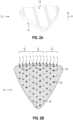
- FIGS. 2A , B show one of the grinding segments 12 of the grinding wheel 10 in a view on the back side 13 of the grinding segment 12 ( FIG. 2A ), which is composed of a bond material 23 and superabrasive particles 24 being arranged according to a predetermined particle design ( FIG. 2B ).
- the grinding segment 12 is fabricated via powder metallurgy, in which a green body is build up layer by layer from a powdery or granular bond material and a plurality of the superabrasive particles 24 and the green body is further processed to form the grinding segment 12 by free-form sintering, hot-pressing, or infiltrating.
- the grinding segment 12 comprises a substantially triangular cross-section with rounded edges perpendicular to a height direction H of the grinding segment 12.
- the back side 13 of the grinding segment 12 is structured and the front side 14 is non-structured.
- FIG. 2B shows the predetermined particle design of the superabrasive particles 24, which are arranged in two patterns.
- Each of the three groups G 1 , G 2 , G 3 includes a first line l 1 , a second line l 2 , a third line l 3 , and a fourth line l 4 of superabrasive particles 24.
- the number of the superabrasive particles 24 in a line can vary and may depend on the cross-section of the grinding segment 12.
- the fourth line l 4 comprises seven superabrasive particles 24 in the first group G 1 , eight superabrasive particles 24 in the second group G 2 , and three superabrasive particles 24 in the third group G 3 .
- the distances between adjacent superabrasive particles 24 in a line can vary and may be adapted to the application of the grinding wheel 10 and the workpiece to be grinded.
- the bond material and superabrasive particles used for the grinding segments should also be different.
- the bond material should be softer to let the new superabrasive particles be exposed more easily and participate in grinding, and, when the workpiece to be grinded is soft, the bond material should be harder to hold the superabrasive particles longer to extend the service life of the grinding segments.
- FIGS. 3A , B show a cross-section of the grinding segment 12 of FIG. 2A in a plane parallel to the height direction H of the grinding segment 12 ( FIG. 3A ) and a detail of FIG. 3A (FIG. 3B ).
- the grinding segment 12 is made of the bond material 23 that is free-form sintered, hot-pressed or infiltrated and of the superabrasive particles 24 being arranged according to the predetermined particle design shown in FIG. 2B .
- the two layers of the bond material 23 are called first layer L 1 and second layer L 2
- the two pattern of the superabrasive particles 24 are called first pattern P 1 and second pattern P 2 .
- the first layer L 1 has a lower surface that is called first lower surface LS 1 and an upper surface that is called first upper surface US 1 , wherein the first lower surface LS 1 is a non-structured lower surface and the first upper surface US 1 is a structured upper surface, and the second layer L 2 has a lower surface that is called second lower surface LS 2 and an upper surface that is called second upper surface US 2 , wherein the second lower surface LS 2 is a structured lower surface and the second upper surface US 2 is a structured upper surface.
- the back side 13 of the grinding segment 12 is predetermined by the second upper surface US 2 , and the front side 14 by the first lower surface LS 1 .
- Each of the first pattern P 1 and second pattern P 2 include the three groups G 1 , G 2 , G 3 of the four lines l 1 , l 2 , l 3 , l 4 of superabrasive particles 24.
- Each group G 1 , G 2 , G 3 includes a first line l 1 , a second line l 2 , a third line l 3 , and a fourth line l 4 of superabrasive particles 24, wherein the four lines l 1 , l 2 , l 3 , l 4 of each group are arranged on different height levels.
- the first lines l 1 of the first, second and third group G 1 , G 2 , G 3 are arranged on a first height level h 1
- the second lines l 2 of the first, second and third group G 1 , G 2 , G 3 are arranged on a second height level h 2
- the third lines l 3 of the first, second and third group G 1 , G 2 , G 3 are arranged on a third height level h 3
- the fourth lines l 4 of the first, second and third group G 1 , G 2 , G 3 are arranged on a fourth height level h 4 .
- the superabrasive particles 24 of the four lines l 1 , l 2 , l 3 , l 4 are arranged on different height levels h 1 , h 2 , h 3 , h 4 , they start grinding at different points of time.
- the superabrasive particles 24 of the fourth lines l 4 start grinding
- the superabrasive particles 24 of the third lines l 3 take over grinding
- the superabrasive particles 24 of the second lines l 2 continue grinding and last the superabrasive particles 24 of the first lines l 1 take over grinding.
- the superabrasive particles 24 of the first line l 1 and second line l 2 differ in the height direction H by a height distance ⁇ 12
- the superabrasive particles 24 of the second line l 2 and third line l 3 differ in the height direction H by a height distance ⁇ 23
- the superabrasive particles 24 of the third line l 3 and fourth line l 4 differ in the height direction H by a height distance ⁇ 34 .
- the superabrasive particles 24 are arranged such that in a group of lines the height distances ⁇ 12 , ⁇ 23 , ⁇ 34 are nearly equal.
- the bond material 23 is at least one of a first bond material and a second bond material, the second bond material being different from the first bond material.
- the first layer L 1 and second layer L 2 may be made from the first bond material that is preferably adapted to the material of the workpiece that should be grinded and selected such that the superabrasive particles 24 are fixed in the first bond material as necessary.
- the bond material used in the contact area to the connection face 17 must be weldable.
- the use of a third layer of the second bond material could support welding of the grinding segment 12 to the basic body 11.
- the third layer of the second bond material would be applied on the structured upper surface US 2 of the second layer L 2 and would have a structured upper surface.
- the first bond material and second bond material could be used for the first layer L 1 and second layer L 2 .
- the first bond material could be selected to fix the superabrasive particles 24 and could be applied to inner regions of the first layer L 1 and second layer L 2
- the second bond material could be selected to strengthen the side surfaces of the grinding segment and could be applied to outer regions of the first layer L 1 and second layer L 2 .
- FIG. 4 shows how a green body 31 for the grinding segment 12 of FIG. 2A may be manufactured stepwise from a powdery bond material 32 and the superabrasive particles 24.
- a sequence of a first step, a second step and a third step is performed two times as a first sequence and a second sequence.
- the sequence of the first step, second step and third step is performed n-times (n ⁇ 2) to manufacture a green body for a segment according to the invention.
- a first portion of the powdery bond material 32 is applied to a lower punch (step 1-1 ).
- a first plurality of the superabrasive particles 24 is arranged on the first portion of powdery bond material 32 according to the predetermined particle design shown in FIG. 2B to build a first layer construction LC 1 ( step 1-2 ), wherein the superabrasive particles 24 are arranged on the same height level in the height direction H.
- the first layer construction LC 1 is compacted via an upper punch that has a structured punching surface ( step 1-3 ).
- the superabrasive particles 24 are shifted in the height direction H such that superabrasive particles 24 of adjacent lines are arranged on different height levels and a structured upper surface 33 is formed.
- the superabrasive particles 24 are arranged in three groups of four lines. Each group comprises a first line l 1 of superabrasive particles 24, a second line l 2 of superabrasive particles 24, a third line l 3 of superabrasive particles 24, and a fourth line l 4 of superabrasive particles 24.
- the second sequence of the first step, second step and third step is performed.
- a second portion of the powdery bond material 32 is applied to the first layer construction LC 1 (step 2-1 ).
- a second plurality of the superabrasive particles 24 is arranged according to the predetermined particle design on the second portion of the powdery bond material 32 to build a second layer construction LC 2 ( step 2-2 ), wherein the superabrasive particles 24 are arranged on the same height level in the height direction H.
- the second layer construction LC 2 is compacted via the structured upper punch ( step 2-3 ). By compacting the second layer construction LC 2 with the structured upper punch, the superabrasive particles 24 are shifted in the height direction H such that superabrasive particles 24 of adjacent lines are arranged on different height levels and a structured upper surface 34 is formed.
- the green body 31 will be further processed to form the grinding segment 12 by free-form sintering, by hot-pressing and/or by infiltrating.
- the green body 31 includes a plane lower surface 35 and the structured upper surface 34. After free-form sintering, hot-pressing, or infiltrating, the lower surface 35 will define the front side 14 of the grinding segment 12 and the upper surface 34 will define the back side 13 of the grinding segment 12.
- FIGS. 5A , B show an alternative grinding segment 42 ( FIG. 5A ) for the grinding wheel 10 of FIG. 1 , the grinding segment 42 being composed of a bond material and superabrasive particles being arranged according to a predetermined particle design ( FIG. 5B ).
- the grinding segment 42 includes a backside 44 that may be used to connect the grinding segment 42 to the connection surface 22 of the basic body 11 and a front side 45 that may be used to grind a workpiece via the grinding wheel 10.
- the grinding segment 42 may substitute the grinding segment 12 and may be connected to the basic body 11 of the grinding wheel 10.
- the grinding segment 12 and the alternative grinding segment 42 are both made of the bond material 23 that is at least one of free-form sintered, hot-pressed, and infiltrated and of the superabrasive particles 24 being arranged according to a predetermined particle design.
- the number of superabrasive particles 24 used for a pattern and the position of the superabrasive particles 24 in a horizontal plane perpendicular to the height direction H are the same for the grinding segments 12, 42, but the height levels of adjacent lines of superabrasive particles 24 and the structure of the backside is different for the grinding segment 12 and the alternative grinding segment 42.
- FIG. 5B shows the predetermined particle design of the superabrasive particles 24, which are arranged in patterns.
- FIGS. 6A , B show a cross-section of the grinding segment 42 of FIG. 5A in a plane parallel to the height direction H of the grinding segment 42 ( FIG. 6A ) and a detail of FIG. 6A (FIG. 6B ).
- the grinding segment 42 is made of the bond material 23 that is free-form sintered or hot-pressed and of the superabrasive particles 24 being arranged according to the predetermined particle design shown in FIG. 5B .
- the first layer L 1 has a lower surface that is called first lower surface LS 1 and an upper surface that is called first upper surface US 1 , wherein the first lower surface LS 1 is a non-structured lower surface and the first upper surface US 1 is a structured upper surface, and the second layer L 2 has a lower surface that is called second lower surface LS 2 and an upper surface that is called second upper surface US 2 , wherein the second lower surface LS 2 is a structured lower surface and the second upper surface US 2 is a structured upper surface.
- the backside 44 of the grinding segment 42 is defined by the second upper surface US 2 , and the front side 45 by the first lower surface LS 1 .
- Each of the first pattern P 1 and second pattern P 2 include the first, second and third group G 1 , G 2 , G 3 of the four lines l 1 , l 2 , l 3 , l 4 of superabrasive particles 24.
- Each group G 1 , G 2 , G 3 includes a first line l 1 of superabrasive particles 24 arranged on a first height level h 1 , a second line l 2 of superabrasive particles 24 arranged on a second height level h 2 , a third line l 3 of superabrasive particles 24 arranged on a third height level h 3 , and a fourth line l 4 of superabrasive particles 24 arranged on a fourth height level h 4 .
- the superabrasive particles 24 of the four lines l 1 , l 2 , l 3 , l 4 are arranged on different height levels, they start grinding at different points of time.
- the superabrasive particles 24 of the fourth lines l 4 start grinding
- the superabrasive particles 24 of the second lines l 2 take over grinding
- the superabrasive particles 24 of the third lines l 3 continue grinding and last the superabrasive particles 24 of the first lines l 1 take over grinding.
- the superabrasive particles 24 of the first line l 1 and second line l 2 differ in the height direction H by a height distance ⁇ 12
- the superabrasive particles 24 of the second line l 2 and third line l 3 differ in the height direction H by a height distance ⁇ 23
- the superabrasive particles 24 of the third line l 3 and fourth line l 4 differ in the height direction H by a height distance ⁇ 34 .
- the superabrasive particles 24 are arranged such that in a group of lines the height distances ⁇ 12 , ⁇ 23 , ⁇ 34 are not equal.
- the grinding segment 42 differs in the height distances ⁇ 12 , ⁇ 23 , ⁇ 34 from the grinding segment 12.
- the height distances ⁇ 12 , ⁇ 23 , ⁇ 34 are nearly equal, and, for the grinding segment 42, the height distances ⁇ 12 , ⁇ 23 , ⁇ 34 vary.
- FIG. 7 shows a further grinding wheel 50 including the cup-shaped basic body 11 and a plurality of grinding segments 52 according to the present invention, the grinding segments 52 being connected via a backside 54 to the basic body 11.
- FIG. 7 shows the grinding wheel 50 in a view on a front side 55 of the grinding segments 52.
- the grinding wheel 50 differs from the grinding wheel 10 in the cross-section of the grinding segments 52 and in the predetermined particle design.
- FIGS. 8A , B show a first variant of a grinding segment ( FIG. 8A ) 62-1 and a second variant of a grinding segment 62-2 ( FIG. 8B ) for the further grinding wheel 50 of FIG. 7 .
- the grinding segments 62-1, 62-2 may substitute the grinding segment 12 of the grinding wheel 10 or the grinding segment 52 of the grinding wheel 50.
- the grinding segments 62-1, 62-2 may be connected via a back side 64-1, 64-2 to the connection face 17 of the basic body 11 and grinding with the grinding wheel 50 may be performed via a front side 65-1, 65-2 of the grinding segments 62-1, 62-2, the front side 64-1, 64-2 being opposite of the back side 64-1, 64-2.
- the grinding segments 62-1, 62-2 are fabricated via powder metallurgy, in which a green body is build up layer by layer from a powdery or granular bond material and a plurality of superabrasive particles and the green body is further processed to form the grinding segments 62-1, 62-2 by free-form sintering, by hot-pressing, and/or by infiltrating.
- the grinding segment 62-1 differs from the grinding segment 62-2 in the back side.
- FIGS. 9A , B show the grinding segments 62-1, 62-2 of FIGS. 8A , B, which are composed of a bond material 66 that is free-form sintered or hot-pressed and of superabrasive particles 67 being arranged according to a first predetermined particle design ( FIG. 9A ) or a second predetermined particle design ( FIG. 9B ).
- the superabrasive particles 67 are arranged in four groups G 1 , G 2 , G 3 , G 3 of lines.
- Each group G 1 , G 2 , G 3 , G 4 includes a first line l 1 of superabrasive particles 67 arranged on a first height level, a second line l 2 of superabrasive particles 67 arranged on a second height level, a third line l 3 of superabrasive particles 67 arranged on a third height level, and a fourth line l 4 of superabrasive particles 67 arranged on a fourth height level, wherein the four lines l 1 , l 2 , l 3 , l 4 of each group are arranged on different height levels in the height direction.
- the number of superabrasive particles 67 in a line can vary and may depend on the cross-section of the grinding segment.
- the first line l 1 comprises one superabrasive particle 67 in the first group G 1 , five superabrasive particles 67 in the second group G 2 , seven superabrasive particles 67 in the third group G 3 , and three superabrasive particles 67 in the fourth group G 4 , and, in the second predetermined particle design shown in FIG.
- the first line l 1 comprises one superabrasive particle 67 in the first group G 1 , seven superabrasive particles 67 in the second group G 2 , ten superabrasive particles 67 in the third group G 3 , and five superabrasive particles 67 in the fourth group G 4 .
- FIGS. 10A , B show a cross-section of further grinding segments 72-1, 72-2 in a plane parallel to a height direction H of the grinding segments 72-1, 72-2, the grinding segment 72-1 including a non-structured first lower surface ( FIG. 10A ) and the grinding segment 72-2 including a structured first lower surface ( FIG. 10B ).
- the grinding segments 72-1, 72-2 may substitute the grinding segment 12 of the grinding wheel 10 or the grinding segment 52 of the grinding wheel 50.
- the grinding segments 72-1, 72-2 are both made of a bond material 73 that is at least one of free-form sintered and hot-pressed and of superabrasive particles 74 being arranged according to a predetermined particle design.
- the four layers of the bond material 73 are called first layer L 1 , second layer L 2 , third layer L 3 , and fourth layer L 4 , and the four pattern of the superabrasive particles 74 are called first pattern P 1 , second pattern P 2 , third pattern P 3 , and fourth pattern P 4 .
- the first layer L 1 has a lower surface that is called first lower surface LS 1 and an upper surface that is called first upper surface US 1
- the second layer L 2 has a lower surface that is called second lower surface LS 2 and an upper surface that is called second upper surface US 2
- the third layer L 3 has a lower surface that is called third lower surface LS 3 and an upper surface that is called third upper surface US 3
- the fourth layer L 4 has a lower surface that is called fourth lower surface LS 4 and an upper surface that is called fourth upper surface US 4 .
- Both grinding segments 72-1, 72-2 have structured second, third, and fourth lower surfaces LS 2 , LS 3 , LS 4 and structured first, second, third, and fourth upper surfaces US 1 , US 2 , US 3 , US 4 , wherein the structured lower surfaces LS 2 , LS 3 , LS 4 and structured upper surfaces US 1 , US 2 , US 3 , US 4 have a first structure that corresponds to the predetermined particle design.
- the grinding segments 72-1, 72-2 differ in the first lower surface LS 1 . Whereas the grinding segment 72-1 ( FIG. 10A ) has a non-structured first lower surface LS 1 , the grinding segment 72-2 ( FIG. 10B ) has a structured first lower surface LS 1 .
- the structured lower surfaces and structured upper surfaces having the first structure are created by compacting the green body via the structured upper punch (see FIG. 4 ).
- the first lower surface LS 1 is created by compacting the green body via the lower upper punch (see FIG. 4 ), the lower punch may be non-structured to generate the grinding segment 72-1 of FIG. 10A or may have a second structure to generate the grinding segment 72-2 of FIG. 10B .
- Each group G 1 , G 2 , G 3 includes a first line l 1 of superabrasive particles 74 arranged on a first height level h 1 , a second line l 2 of superabrasive particles 74 arranged on a second height level h 2 , a third line l 3 of superabrasive particles 74 arranged on a third height level h 3 , and a fourth line l 4 of superabrasive particles 74 arranged on a fourth height level h 4 .
- the grinding segments 72-1, 72-2 may be connected via a back side 75-1, 75-2 to a connection face of a basic body and grinding may be performed via a front side 76-1, 76-2 of the grinding segments 72-1, 72-2, the front side 76-1, 76-2 being opposite of the back side 75-1, 75-2.
- the back sides 75-1, 75-2 of the grinding segments 72-1, 72-2 are defined by the fourth upper surface US 4
- the front sides 76-1, 76-2 of the grinding segments 72-1, 72-2 are defined by the first lower surface LS 1 .
- the grinding segment 72-2 may have the advantage that the surface area of the front side 76-1 is reduced compared to the grinding segment 72-1.
- the structure of the first lower surface LS 1 has no impact on the distribution of the superabrasive particles 74.
Abstract
Grinding segment (12) made of a bond material that is at least one of free-form sintered, hotpressed and infiltrated and of superabrasive particles being arranged according to a predetermined particle design, the grinding segment having a height in a height direction (H) and the grinding segment being configured to be connected to a connection surface of a basic body of a tool bit, the grinding segment (12) comprising M, M ≥ 2, layers of the bond material, the layers being stacked in the height direction (H), and N, N ≥ 1, patterns of the superabrasive particles, the patterns being stacked in the height direction (H). Each of the M layers of the bond material has at least one of a structured lower surface and a structured upper surface, wherein the structured lower surfaces and/or structured upper surfaces of the M layers have a first structure that corresponds to the predetermined particle design of the superabrasive particles.
Description
- The present invention relates to tool bits for grinding materials such as concrete, granite, stone, marble or the like and grinding segments to be connected on such tool bits for grinding, and more particularly to grinding segments in which superabrasive particles are distributed according to a predetermined particle design in a bond material and by which the grinding performance and service life of the tool bit can be improved.
- Tool bits for grinding are composed of a disc-shaped or cup-shaped basic body, a plurality of grinding segments connected to the basic body, and a plurality of suction holes arranged in the basic body and configured to discharge removed particles. The basic body includes an outer circumferential section, an inner section configured to connect the tool bit to a motorized power tool, and a transition section arranged between the circumferential section and inner section. The grinding segments are connected to the basic body by brazing, soldering, welding or the like, and the suction holes are arranged in at least one of the circumferential section and the transition section of the basic body.
- Typical grinding segments are manufactured by mixing superabrasive particles with a suitable bond material (e.g., powder). The mixture is compressed in a mold to form a green body, which is then consolidated by free-form sintering, hot-pressing, or infiltrating to form a single grinding segment. Finally, the grinding segments are connected by brazing, soldering, welding or the like to the basic body to form the final tool bit for grinding.
- During the process of mixing the superabrasive particles with the bond material, the superabrasive particles have a much larger size compared to the particles of the bond material and so tend to freely flow, so that under the condition of a finite overall blending ratio of the superabrasive particles to the bond material, the superabrasive particles may be highly concentrated in certain regions or very deficient below the average concentration in other regions to cause irregular or non-uniform distribution of the superabrasive particles within the grinding segments.
- During grinding operation, the grinding wheel rotates at a certain speed and removes surface parts of stone, concrete, marble, or the like with the torque originating from the motorized power tool, and during the course, the superabrasive particles on the grinding segments experience severe load due to the reactive force of the object in the form of friction, with the result that the superabrasive particles can be worn out, loosened, or even broken.
- When such load of friction with the object exceeds the force binding the bond material with the superabrasive particles, the superabrasive particles pull out and newly emerging superabrasive particles take over the machining duty, and thus in such a manner the self-regeneration process repeats itself to enable continuation of machining operation with the depleted thickness of the grinding segments.
- In the case the superabrasive particles are segregated to certain regions, the load of friction imposed on an individual superabrasive particle would be decreased. However, during initial time after the start of grinding, the superabrasive particles would be in active working and so dulled in the sharp grinding segments or can be subjected to a degradation together with the bond material due to an abrupt frictional heat generation, however the self-regeneration remains at a low level, so that deformation or unevenness on the surface of the grinding wheel can result.
- In contrast, the superabrasive particles in the sections of the grinding segments, where the concentration of the superabrasive particles is relatively low, are subjected to larger load of friction or impact per unit particle and therefore the superabrasive particles are easily broken, constituting a cause of decreasing the service life of the tool bit.
- Therefore, the present invention was created to resolve the problems with the prior art as described above, and the object of the present invention is to provide a grinding segment and a tool bit for grinding equipped with the grinding segments, which allow precise grinding operation thanks to the defined distribution of the superabrasive particles, and which make possible the marked improvement in the grinding performance and/or in the service life of tool bits for grinding.
- The object is achieved according to an aspect of the invention by a grinding segment characterized in that each of the M layers of the bond material has at least one of a structured lower surface and a structured upper surface, wherein the structured lower surfaces and/or structured upper surfaces of the M layers have a first structure that corresponds to the predetermined particle design of the superabrasive particles.
- The grinding segment is fabricated via powder metallurgy, in which a green body is build up layer by layer and then the green body is further processed by free-form sintering, by hot-pressing and/or by infiltrating to form the final grinding segment. The grinding segment includes a bond material that is at least one of free-form sintered, hot pressed and infiltrated and a plurality of superabrasive particles being arranged according to a predetermined particle design and bonded in the bond material.
- The grinding segment according to the present invention is composed of at least two layers of the bond material and of at least one pattern of the superabrasive particles, the layers and patterns being stacked in the height direction of the grinding segment. Each of the layers of the bond material has a lower surface and an upper surface and at least one of the lower and upper surfaces of each layer is a structured surface having a first structure that corresponds to the predetermined particle design of the superabrasive particles. The structured lower and/or upper surfaces of each layer enable that the superabrasive particles of a pattern can be arranged on different height levels with height differences between adjacent height levels. The height levels will preferably be selected such that the superabrasive particles of a following height level will be opened at a certain wearout of the superabrasive particles of the previous height level. During grinding with the tool bit for grinding, the active superabrasive particles wear out and their size in the height direction is reduced.
- In a preferred embodiment, the M layers of the bond material include at least a first layer having a first lower surface and a first upper surface, wherein the first upper surface has the first structure, and the first lower surface is non-structured. The first layer has a non-structured first lower surface and a structured first upper surface. The non-structured first lower surface may be used as front side of the grinding segment, the front side being opposite of a back side of the grinding segment, and the grinding segment being connected via the back side to the basic body of a tool bit.
- In another preferred embodiment, the M layers of the bond material include at least a first layer having a first lower surface and a first upper surface, wherein the first upper surface has the first structure, and the first lower surface has a second structure that is different from the first structure of the first upper surface. The first layer has a structured first upper surface and a structured first lower surface, the first structure of the first upper surface being different from the second structure of the first lower surface. The structured first lower surface may be used as front side of the grinding segment, the front side being opposite of a back side of the grinding segment, and the grinding segment being connected via the back side to a basic body of a tool bit. The use of a structured first lower surface as front side may have the advantage that the surface area of the front side that is in contact with the basic body of the tool bit is reduced. In case of connecting the grinding segments via methods such as resistance welding to the basic body of the tool bit, a decreased surface area may be preferred.
- Preferably, the M layers of the bond material include at least a M-th layer having a M-th lower surface and a M-th upper surface, wherein the M-th lower surface and the M-th upper surface have the first structure. The structured M-th upper surface may be used as back side of the grinding segment, the grinding segment being connected via the back side to a basic body of a tool bit.
- Preferably, the bond material is at least one of a first bond material and a second bond material, the second bond material being different from the first bond material. The grinding segment is composed of at least two layers of the bond material and of at least two patterns of the superabrasive particles. The superabrasive particles are arranged according to a predetermined particle design and fixed by the bond material that is at least one of free-form sintered and hot-pressed. The first bond material may be used to fix the superabrasive particles and the second bond material may be used in a contact area with the connection face to allow welding of the grinding segment. Alternatively, or additionally, the layers of bond material may comprise a first bond material and second bond material, the first bond material may be applied to inner regions of the layers to fix the superabrasive particles and the second bond material may be applied to outer regions of the layers to strengthen the side surfaces of the grinding segment.
- Preferably, each pattern of superabrasive particles includes at least two groups of K, K ≥ 2 lines of the superabrasive particles, the superabrasive particles of adjacent lines being arranged on different height levels in the height direction. The grinding segment is composed of at least one pattern of the superabrasive particles, the patterns being stacked in the height direction. In each pattern, the superabrasive particles are arranged according to the predetermined particle design that includes two or more groups of at least two lines of the superabrasive particles. The number of groups is preferably adapted to the abrasiveness of the workpiece to be grinded and/or the expected lifetime of the grinding segment. In a line, the superabrasive particles are arranged on a similar height level in the height direction, and the superabrasive particles of adjacent lines are arranged on different height levels. The number of lines and the height levels of the different types of lines may be selected such that the superabrasive particles of the next type of lines are opened before the superabrasive particles positioned just above have been worn out at a certain percentage, so that self-regeneration of the superabrasive particles may be repeated for the service time of the grinding segment.
- When all lines of a pattern were fallen out, the next pattern of superabrasive particles will become active. The height levels of the last type of lines of a previous pattern and the first type of lines of a following pattern may be selected such that the superabrasive particles of the next type of lines are opened before the superabrasive particles of the last line positioned just above have been worn out at a certain percentage, so that self-regeneration of the superabrasive particles may be repeated for the service time of the grinding segment.
- Preferably, each of the at least two groups comprises a first line of superabrasive particles, a second line of superabrasive particles, and a third line of superabrasive particles, wherein the first lines being arranged on a first height level, the second lines being arranged on a second height level, and the third lines being arranged on a third height level, and wherein the first height level, second height level and third height level being different from each other in the height direction. In each pattern of the grinding segment, the superabrasive particles are arranged according to the predetermined particle design that includes two or more groups of a first line, a second line, and a third line of superabrasive particles, wherein the superabrasive particles of the first, second, and third line are arranged on the first, second, and third height level.
- In a first preferred embodiment, the height differences between the first and second height level and between the second and third height level are substantially equal. The lines of superabrasive particles of each group define a linear arrangement and the superabrasive particles of the adjacent lines will become active one after the other.
- In a second preferred embodiment, the height differences between the first and second height level and between the second and third height level are different from each other. The lines of superabrasive particles of each group define a non-linear arrangement that helps in retaining a more uniform wearout at the edges of the grinding segment and keeping the tool bit grinding for the service life.
- Preferably, each of the at least two groups further comprises a fourth line of superabrasive particles, wherein the fourth lines being arranged on a fourth height level, and wherein the fourth height level is different from the first height level, second height level and third height level in the height direction. By using four lines of superabrasive particles arranged on different height levels the height difference between the lines can be reduced. Preferably, the number of lines of each group and the height differences between the lines may be selected such that the superabrasive particles of a line will be opened at a certain wearout of the superabrasive particles of the previous line.
- Preferably, each of the at least two groups may further comprise a fifth line of superabrasive particles, wherein the fifth lines being arranged on a fifth height level, and wherein the fifth height level is different from the first height level, second height level, third height level, and fourth height level in the height direction. By using five lines of superabrasive particles arranged on different height levels the height differences between the lines can be reduced. Preferably, the number of lines of each group and the height differences between the lines may be selected such that the superabrasive particles of a line will be opened at a certain wearout of the superabrasive particles of the previous line.
- The object is also achieved according to another aspect of the invention by a tool bit for grinding, comprising a basic body including an inner section configured to connect the tool bit to a power tool, and a circumferential section with a connection surface, and two or more grinding segments according to the invention, wherein the grinding segments are connected to the connection surface.
- The tool bit comprises a disc-shaped or cup-shaped basic body and two or more grinding segments. The grinding segments comprise a front side and a back side opposite of the front side, and the grinding segments being connected via the back side to the basic body. A tool bit according to the invention may have a similar performance over the lifetime since the superabrasive particles are distributed in the grinding segment according to the predetermined particle design.
- Preferably, the grinding segments are connected to the connection surface with the upper surface of the M-th layer of the bond material. The grinding segments are composed of M, M ≥ 2 layers of the bond material and of N, N ≥ 1 patterns of the superabrasive particles, the layers and patterns being stacked in the height direction of the grinding segment. Each of the M layers of the bond material has at least one of a structured lower surface and a structured upper surface. By using the structured upper surface of the M-th layer as back side ....
- Preferably, the tool bit further comprises a plurality of suction holes being arranged in at least one of the circumferential section or a transition section that is arranged between the circumferential section and inner section.
- The aspects of the invention are described or explained in more detail below, purely by way of example, with reference to working examples shown schematically in the drawing. Identical elements are labelled with the same reference numerals in the figures. The described embodiments are generally not shown true in scale, and they are also not to be interpreted as limiting the invention. Specifically,
- FIGS. 1A, B
- show a grinding wheel including a basic body and a plurality of grinding segments in a view on a front side of the grinding segments (
FIG. 1A ) and in a cross-section parallel to an axis of rotation of the grinding wheel (FIG. 1B ), - FIGS. 2A, B
- show one of the grinding segments of the grinding wheel of
FIG. 1 in a view on a back side of the grinding segment (FIG. 2A ), the grinding segment being composed of a bond material and superabrasive particles being arranged according to a predetermined particle design (FIG. 2B ), - FIGS. 3A, B
- show a cross-section of the grinding segment of
FIG. 2A in a plane parallel to a height direction of the grinding segment (FIG. 3A ) and a detail ofFIG. 3A (FIG. 3B ), - FIG. 4
- shows how a green body for the grinding segment of
FIG. 2A can be manufactured stepwise, - FIGS. 5A, B
- show an alternative grinding segment for the grinding wheel of
FIG. 1 (FIG. 5A ), the grinding segment being composed of a bond material and superabrasive particles being arranged according to a predetermined particle design (FIG. 5B ), - FIGS. 6A, B
- show a cross-section of the grinding segment of
FIG. 5A in a plane parallel to a height direction of the grinding segment (FIG. 6A ) and a detail ofFIG. 6A (FIG. 6B ), - FIG. 7
- shows a further grinding wheel including a basic body and a plurality of grinding segments in a view on a front side of the grinding segments,
- FIGS. 8A, B
- show a first variant of a grinding segment (
FIG. 8A ) and a second variant of a grinding segment (FIG. 8B ) for the further grinding wheel ofFIG. 7 , - FIGS. 9A, B
- show the grinding segments of
FIGS. 8A , B, which are composed of a bond material and superabrasive particles being arranged according to a first predetermined particle design (FIG. 9A ) and a second predetermined particle design (FIG. 9B ), - FIGS. 10A, B
- show a cross-section of a further grinding segment in a plane parallel to a height direction of the grinding segment, the grinding segment including a nonstructured first lower surface (
FIG. 10A ) and a structured first lower surface (FIG. 10B ). - Reference will now be made in detail to the present preferred embodiment, an example of which is illustrated in the accompanying drawings. It is to be understood that the technology disclosed herein is not limited in its application to the details of construction and the arrangement of components set forth in the following description or illustrated in the drawings. The technology disclosed herein is capable of other embodiments and of being practiced or of being carried out in various ways.
- Also, it is to be understood that the phraseology and terminology used herein is for the purpose of description and should not be regarded as limiting. All definitions, as defined and used herein, should be understood to control over dictionary definitions, definitions in documents incorporated by reference, and/or ordinary meanings of the defined terms. The indefinite articles "a" and "an", as used herein in the specification and in the claims, unless clearly indicated to the contrary, should be understood to mean "at least one". The phrase "and/or", as used herein in the specification and in the claims, should be understood to mean "either or both" of the elements so conjoined, i.e., elements that are conjunctively present in some cases and disjunctively present in other cases. Multiple elements listed with "and/or" should be construed in the same fashion, i.e., "one or more" of the elements so conjoined. Other elements may optionally be present other than the elements specifically identified by the "and/or" clause, whether related or unrelated to those elements specifically identified.
- As used herein in the specification and in the claims, "or" should be understood to have the same meaning as "and/or" as defined above. For example, when separating items in a list, "or" or "and/or" shall be interpreted as being inclusive, i.e., the inclusion of at least one, but also including more than one of a number or list of elements, and, optionally, additional unlisted items. Only terms clearly indicated to the contrary, such as "only one of" or "exactly one of", or, when used in the claims, "consisting of" will refer to the inclusion of exactly one element of a number or list of elements. In general, the term "or" as used herein shall only be interpreted as indicating exclusive alternatives (ke. "one or the other but not both") when preceded by terms of exclusivity, such as "either", "one of", "only one of", or "exactly one of", "consisting essentially of", when used in the claims, shall have its ordinary meaning as used in the field of patent law.
- As used herein in the specification and in the claims, the phrase "at least one" in reference to a list of one or more elements, should be understood to mean at least one element selected from any one or more of the elements in the list of elements, but not necessarily including at least one of each and every element specifically listed within the list of elements and not excluding any combinations of elements in the list of elements. This definition also allows that elements may optionally be present other than the elements specifically identified within the list of elements to which the phrase "at least one" refers, whether related or unrelated to those elements specifically identified.
- The use of "including, or "comprising, or "having" and variations thereof herein is meant to encompass the items listed thereafter and equivalents thereof as well as additional items. Unless limited otherwise, the terms "connected", "coupled", and "mounted", and variations thereof herein are used broadly and encompass direct and indirect connections, couplings, and mountings. In addition, the terms "connected" and "coupled", and variations thereof are not restricted to physical or mechanical connections or couplings.
- As used herein, the term "segment" means a piece or fragment substantially in the form of a sector, particularly used for the purpose of cutting, grinding, sawing, drilling or the like as well. The term "bond material" refers to a material to which superabrasive particles may be bonded. Bond materials typically consist of a base powder, which is combined with compression auxiliaries and additives which serve to optimize the properties of the base powder material with regard to the strength and wear rate of the segments. The base powder may consist of one base material or be composed of several base materials.
- Th term "superabrasive particles" refer to particles of either natural or synthetic diamond, super hard crystalline, or polycrystalline substance, or mixtures of substances and include but are not limited to diamond, polycrystalline diamond (PCD), cubic boron nitride (CBN), and polycrystalline cubic boron nitride (PCBN). The term "predetermined particle design" refers to a non-random particle design of the superabrasive particles that is identified prior to construction of a tool bit, and which individually places or locates each superabrasive particle in a defined relationship with the other superabrasive particles, and with the configuration of the tool bit.
-
FIGS. 1A , B show atool bit 10 for grinding according to the present invention. Thetool bit 10 is formed as cup-shaped grinding wheel and comprises a cup-shapedbasic body 11, a plurality of grindingsegments 12 according to the present invention, and a plurality of suction holes 13. The grindingsegments 12 are connected via aback side 14 to thebasic body 11.FIG. 1A shows the grindingwheel 10 in a view on afront side 15 opposite to theback side 14 of the grindingsegments 12 andFIG. 1B the grindingwheel 10 in a cross-section parallel to an axis ofrotation 16 of thegrinding wheel 10. - The
basic body 11 is composed of an outercircumferential section 17, aninner section 18, and aconical transition section 19 that is arranged between thecircumferential section 17 andinner section 18. Thecircumferential section 17 is ring-shaped and includes severalconcentrical grooves 21, which form astructured connection surface 22, to which the grindingsegments 12 are fixed, e.g., by brazing, soldering, welding, or the like as well. Alternatively, thecircumferential section 17 may include a plane connection surface, to which the grindingsegments 12 can be fixed. The grindingsegments 12 may have a L-shaped, boomerang-shaped, rectangular, triangular or the like as well cross-section perpendicular to a height direction of the grinding segment. - The suction holes 13 may be arranged in the
circumferential section 17 or in thetransition section 19 and may be equally distributed in one row or in two concentric rows; alternatively, first suction holes may be arranged in thecircumferential section 17 and second suction holes in thetransition section 19. In the embodiment ofFIG. 1 , the grindingsegments 12 and suction holes 13 are equally spaced along thecircumferential section 17, and in the circumferential direction, each of the suction holes 13 is arranged between two adjacent grindingsegments 12. The number, size and/or position of the suction holes 13 may vary and be selected such that a discharge of particles removed by the grindingwheel 10 can be optimized. The suction holes 13 can create an airstream, which allows to cool the grindingsegments 12 and to discharge removed particles during grinding operation. - There are a variety of styles of grinding wheels for different workpieces to be grinded and different requirements. The dimension and number of their grinding segments determine how aggressive the grinding wheel is.
-
FIGS. 2A , B show one of the grindingsegments 12 of thegrinding wheel 10 in a view on theback side 13 of the grinding segment 12 (FIG. 2A ), which is composed of abond material 23 andsuperabrasive particles 24 being arranged according to a predetermined particle design (FIG. 2B ). - The grinding
segment 12 is fabricated via powder metallurgy, in which a green body is build up layer by layer from a powdery or granular bond material and a plurality of thesuperabrasive particles 24 and the green body is further processed to form the grindingsegment 12 by free-form sintering, hot-pressing, or infiltrating. The grindingsegment 12 comprises a substantially triangular cross-section with rounded edges perpendicular to a height direction H of the grindingsegment 12. Theback side 13 of the grindingsegment 12 is structured and thefront side 14 is non-structured. -
FIG. 2B shows the predetermined particle design of thesuperabrasive particles 24, which are arranged in two patterns. Each pattern includes a first group G1, a second group G2 and a third group G3 of four (K = 4) lines ofsuperabrasive particles 24. Each of the three groups G1, G2, G3 includes a first line l1 , a second line l2 , a third line l3 , and a fourth line l4 ofsuperabrasive particles 24. - The number of the
superabrasive particles 24 in a line can vary and may depend on the cross-section of the grindingsegment 12. As an example, the fourth line l4 comprises sevensuperabrasive particles 24 in the first group G1, eightsuperabrasive particles 24 in the second group G2, and threesuperabrasive particles 24 in the third group G3. The distances between adjacentsuperabrasive particles 24 in a line can vary and may be adapted to the application of thegrinding wheel 10 and the workpiece to be grinded. - As different workpieces to be grinded, such as concrete, granite, stone, marble, and the like, have different natures, the bond material and superabrasive particles used for the grinding segments should also be different. When the workpiece to be grinded is hard, the bond material should be softer to let the new superabrasive particles be exposed more easily and participate in grinding, and, when the workpiece to be grinded is soft, the bond material should be harder to hold the superabrasive particles longer to extend the service life of the grinding segments.
-
FIGS. 3A , B show a cross-section of the grindingsegment 12 ofFIG. 2A in a plane parallel to the height direction H of the grinding segment 12 (FIG. 3A ) and a detail ofFIG. 3A (FIG. 3B ). The grindingsegment 12 is made of thebond material 23 that is free-form sintered, hot-pressed or infiltrated and of thesuperabrasive particles 24 being arranged according to the predetermined particle design shown inFIG. 2B . - The grinding
segment 12 is composed of two (M = 2) layers of thebond material 23 and of two (N = 2) patterns of thesuperabrasive particles 24, the two layers and two patterns being stacked in a direction of stacking that is parallel to the height direction H of the grindingsegment 12. The two layers of thebond material 23 are called first layer L1 and second layer L2 , and the two pattern of thesuperabrasive particles 24 are called first pattern P1 and second pattern P2 . - The first layer L1 has a lower surface that is called first lower surface LS1 and an upper surface that is called first upper surface US1 , wherein the first lower surface LS1 is a non-structured lower surface and the first upper surface US1 is a structured upper surface, and the second layer L2 has a lower surface that is called second lower surface LS2 and an upper surface that is called second upper surface US2 , wherein the second lower surface LS2 is a structured lower surface and the second upper surface US2 is a structured upper surface. The
back side 13 of the grindingsegment 12 is predetermined by the second upper surface US2, and thefront side 14 by the first lower surface LS1. - Each of the first pattern P1 and second pattern P2 include the three groups G1, G2, G3 of the four lines l1, l2, l3, l4 of
superabrasive particles 24. Each group G1, G2, G3 includes a first line l1, a second line l2, a third line l3, and a fourth line l4 ofsuperabrasive particles 24, wherein the four lines l1, l2, l3, l4 of each group are arranged on different height levels. In each pattern P1, P2, the first lines l1 of the first, second and third group G1, G2, G3 are arranged on a first height level h1 , the second lines l2 of the first, second and third group G1, G2, G3 are arranged on a second height level h2 , the third lines l3 of the first, second and third group G1, G2, G3 are arranged on a third height level h3 , and the fourth lines l4 of the first, second and third group G1, G2, G3 are arranged on a fourth height level h4 . - Because the
superabrasive particles 24 of the four lines l1, l2, l3, l4 are arranged on different height levels h1, h2, h3, h4, they start grinding at different points of time. During grinding with the grindingsegment 12, thesuperabrasive particles 24 of the fourth lines l4 start grinding, thesuperabrasive particles 24 of the third lines l3 take over grinding, then thesuperabrasive particles 24 of the second lines l2 continue grinding and last thesuperabrasive particles 24 of the first lines l1 take over grinding. - In each pattern of
superabrasive particles 24, thesuperabrasive particles 24 of the first line l1 and second line l2 differ in the height direction H by a height distance δ12 , thesuperabrasive particles 24 of the second line l2 and third line l3 differ in the height direction H by a height distance δ23 , and thesuperabrasive particles 24 of the third line l3 and fourth line l4 differ in the height direction H by a height distance δ34 . Thesuperabrasive particles 24 are arranged such that in a group of lines the height distances δ12, δ23, δ34 are nearly equal. - The
bond material 23 is at least one of a first bond material and a second bond material, the second bond material being different from the first bond material. In the embodiment shown inFIG. 3B , the first layer L1 and second layer L2 may be made from the first bond material that is preferably adapted to the material of the workpiece that should be grinded and selected such that thesuperabrasive particles 24 are fixed in the first bond material as necessary. - If the grinding
segment 12 should be connected to thebasic body 11 by welding, the bond material used in the contact area to theconnection face 17 must be weldable. The use of a third layer of the second bond material could support welding of the grindingsegment 12 to thebasic body 11. The third layer of the second bond material would be applied on the structured upper surface US2 of the second layer L2 and would have a structured upper surface. - Instead of using only the first bond material for the first layer L1 and second layer L2, the first bond material and second bond material could be used for the first layer L1 and second layer L2. The first bond material could be selected to fix the
superabrasive particles 24 and could be applied to inner regions of the first layer L1 and second layer L2, and the second bond material could be selected to strengthen the side surfaces of the grinding segment and could be applied to outer regions of the first layer L1 and second layer L2. -
FIG. 4 shows how agreen body 31 for the grindingsegment 12 ofFIG. 2A may be manufactured stepwise from apowdery bond material 32 and thesuperabrasive particles 24. To manufacture thegreen body 31, a sequence of a first step, a second step and a third step is performed two times as a first sequence and a second sequence. Generally, the sequence of the first step, second step and third step is performed n-times (n ≥ 2) to manufacture a green body for a segment according to the invention. - In the first step of the first sequence, a first portion of the
powdery bond material 32 is applied to a lower punch (step 1-1). In the second step of the first sequence, a first plurality of thesuperabrasive particles 24 is arranged on the first portion ofpowdery bond material 32 according to the predetermined particle design shown inFIG. 2B to build a first layer construction LC1 (step 1-2), wherein thesuperabrasive particles 24 are arranged on the same height level in the height direction H. In the third step of the first sequence, the first layer construction LC1 is compacted via an upper punch that has a structured punching surface (step 1-3). - By compacting the first layer construction LC1 with the structured upper punch, the
superabrasive particles 24 are shifted in the height direction H such thatsuperabrasive particles 24 of adjacent lines are arranged on different height levels and a structuredupper surface 33 is formed. After step 1-3, thesuperabrasive particles 24 are arranged in three groups of four lines. Each group comprises a first line l1 ofsuperabrasive particles 24, a second line l2 ofsuperabrasive particles 24, a third line l3 ofsuperabrasive particles 24, and a fourth line l4 ofsuperabrasive particles 24. - After the first sequence, the second sequence of the first step, second step and third step is performed. In the first step of the second sequence, a second portion of the
powdery bond material 32 is applied to the first layer construction LC1 (step 2-1). In the second step of the second sequence, a second plurality of thesuperabrasive particles 24 is arranged according to the predetermined particle design on the second portion of thepowdery bond material 32 to build a second layer construction LC2 (step 2-2), wherein thesuperabrasive particles 24 are arranged on the same height level in the height direction H. In the third step of the second sequence, the second layer construction LC2 is compacted via the structured upper punch (step 2-3). By compacting the second layer construction LC2 with the structured upper punch, thesuperabrasive particles 24 are shifted in the height direction H such thatsuperabrasive particles 24 of adjacent lines are arranged on different height levels and a structuredupper surface 34 is formed. - The
green body 31 will be further processed to form the grindingsegment 12 by free-form sintering, by hot-pressing and/or by infiltrating. Thegreen body 31 includes a planelower surface 35 and the structuredupper surface 34. After free-form sintering, hot-pressing, or infiltrating, thelower surface 35 will define thefront side 14 of the grindingsegment 12 and theupper surface 34 will define theback side 13 of the grindingsegment 12. -
FIGS. 5A , B show an alternative grinding segment 42 (FIG. 5A ) for thegrinding wheel 10 ofFIG. 1 , the grindingsegment 42 being composed of a bond material and superabrasive particles being arranged according to a predetermined particle design (FIG. 5B ). The grindingsegment 42 includes abackside 44 that may be used to connect the grindingsegment 42 to theconnection surface 22 of thebasic body 11 and afront side 45 that may be used to grind a workpiece via the grindingwheel 10. - The grinding
segment 42 may substitute the grindingsegment 12 and may be connected to thebasic body 11 of thegrinding wheel 10. The grindingsegment 12 and thealternative grinding segment 42 are both made of thebond material 23 that is at least one of free-form sintered, hot-pressed, and infiltrated and of thesuperabrasive particles 24 being arranged according to a predetermined particle design. The number ofsuperabrasive particles 24 used for a pattern and the position of thesuperabrasive particles 24 in a horizontal plane perpendicular to the height direction H are the same for the grindingsegments superabrasive particles 24 and the structure of the backside is different for the grindingsegment 12 and thealternative grinding segment 42. -
FIG. 5B shows the predetermined particle design of thesuperabrasive particles 24, which are arranged in patterns. Each of the pattern includes a first group G1, second group G2 and third group G3 of four (K = 4) lines ofsuperabrasive particles 24, and each group G1, G2, G3 includes a first line l1 , second line l2 , third line l3 , and fourth line l4 ofsuperabrasive particles 24. -
FIGS. 6A , B show a cross-section of the grindingsegment 42 ofFIG. 5A in a plane parallel to the height direction H of the grinding segment 42 (FIG. 6A ) and a detail ofFIG. 6A (FIG. 6B ). - The grinding
segment 42 is made of thebond material 23 that is free-form sintered or hot-pressed and of thesuperabrasive particles 24 being arranged according to the predetermined particle design shown inFIG. 5B . The grindingsegment 42 is composed of two (M = 2) layers L1 , L2 of thebond material 23 and of two (N = 2) patterns P1 , P2 ofsuperabrasive particles 24, the two layers L1, L2 and two patterns P1, P2 being stacked in a direction of stacking that is parallel to the height direction H of the grindingsegment 42. - The first layer L1 has a lower surface that is called first lower surface LS1 and an upper surface that is called first upper surface US1 , wherein the first lower surface LS1 is a non-structured lower surface and the first upper surface US1 is a structured upper surface, and the second layer L2 has a lower surface that is called second lower surface LS2 and an upper surface that is called second upper surface US2 , wherein the second lower surface LS2 is a structured lower surface and the second upper surface US2 is a structured upper surface. The
backside 44 of the grindingsegment 42 is defined by the second upper surface US2, and thefront side 45 by the first lower surface LS1. - Each of the first pattern P1 and second pattern P2 include the first, second and third group G1, G2, G3 of the four lines l1, l2, l3, l4 of
superabrasive particles 24. Each group G1, G2, G3 includes a first line l1 ofsuperabrasive particles 24 arranged on a first height level h1 , a second line l2 ofsuperabrasive particles 24 arranged on a second height level h2 , a third line l3 ofsuperabrasive particles 24 arranged on a third height level h3 , and a fourth line l4 ofsuperabrasive particles 24 arranged on a fourth height level h4 . - Because the
superabrasive particles 24 of the four lines l1, l2, l3, l4 are arranged on different height levels, they start grinding at different points of time. During grinding with the grindingsegment 42, thesuperabrasive particles 24 of the fourth lines l4 start grinding, thesuperabrasive particles 24 of the second lines l2 take over grinding, then thesuperabrasive particles 24 of the third lines l3 continue grinding and last thesuperabrasive particles 24 of the first lines l1 take over grinding. - In each pattern P1, P2 of
superabrasive particles 24, thesuperabrasive particles 24 of the first line l1 and second line l2 differ in the height direction H by a height distance δ12 , thesuperabrasive particles 24 of the second line l2 and third line l3 differ in the height direction H by a height distance δ23, and thesuperabrasive particles 24 of the third line l3 and fourth line l4 differ in the height direction H by a height distance δ34 . Thesuperabrasive particles 24 are arranged such that in a group of lines the height distances δ12, δ23, δ34 are not equal. - The grinding
segment 42 differs in the height distances δ12, δ23, δ34 from the grindingsegment 12. For the grindingsegment 12, the height distances δ12, δ23, δ34 are nearly equal, and, for the grindingsegment 42, the height distances δ12, δ23, δ34 vary. -
FIG. 7 shows afurther grinding wheel 50 including the cup-shapedbasic body 11 and a plurality of grindingsegments 52 according to the present invention, the grindingsegments 52 being connected via abackside 54 to thebasic body 11.FIG. 7 shows the grindingwheel 50 in a view on afront side 55 of the grindingsegments 52. The grindingwheel 50 differs from the grindingwheel 10 in the cross-section of the grindingsegments 52 and in the predetermined particle design. -
FIGS. 8A , B show a first variant of a grinding segment (FIG. 8A ) 62-1 and a second variant of a grinding segment 62-2 (FIG. 8B ) for thefurther grinding wheel 50 ofFIG. 7 . The grinding segments 62-1, 62-2 may substitute the grindingsegment 12 of thegrinding wheel 10 or the grindingsegment 52 of thegrinding wheel 50. - The grinding segments 62-1, 62-2 may be connected via a back side 64-1, 64-2 to the
connection face 17 of thebasic body 11 and grinding with the grindingwheel 50 may be performed via a front side 65-1, 65-2 of the grinding segments 62-1, 62-2, the front side 64-1, 64-2 being opposite of the back side 64-1, 64-2. - The grinding segments 62-1, 62-2 are fabricated via powder metallurgy, in which a green body is build up layer by layer from a powdery or granular bond material and a plurality of superabrasive particles and the green body is further processed to form the grinding segments 62-1, 62-2 by free-form sintering, by hot-pressing, and/or by infiltrating. The grinding segment 62-1 differs from the grinding segment 62-2 in the back side.
-
FIGS. 9A , B show the grinding segments 62-1, 62-2 ofFIGS. 8A , B, which are composed of abond material 66 that is free-form sintered or hot-pressed and ofsuperabrasive particles 67 being arranged according to a first predetermined particle design (FIG. 9A ) or a second predetermined particle design (FIG. 9B ). - According to the first and second predetermined particle designs, the
superabrasive particles 67 are arranged in four groups G1, G2, G3 , G3 of lines. Each group G1, G2, G3, G4 includes a first line l1 ofsuperabrasive particles 67 arranged on a first height level, a second line l2 ofsuperabrasive particles 67 arranged on a second height level, a third line l3 ofsuperabrasive particles 67 arranged on a third height level, and a fourth line l4 ofsuperabrasive particles 67 arranged on a fourth height level, wherein the four lines l1, l2, l3, l4 of each group are arranged on different height levels in the height direction. - The number of
superabrasive particles 67 in a line can vary and may depend on the cross-section of the grinding segment. As an example, in the first predetermined particle design shown inFIG. 9A , the first line l1 comprises onesuperabrasive particle 67 in the first group G1, fivesuperabrasive particles 67 in the second group G2, sevensuperabrasive particles 67 in the third group G3, and threesuperabrasive particles 67 in the fourth group G4, and, in the second predetermined particle design shown inFIG. 9B , the first line l1 comprises onesuperabrasive particle 67 in the first group G1, sevensuperabrasive particles 67 in the second group G2, tensuperabrasive particles 67 in the third group G3, and fivesuperabrasive particles 67 in the fourth group G4. -
FIGS. 10A , B show a cross-section of further grinding segments 72-1, 72-2 in a plane parallel to a height direction H of the grinding segments 72-1, 72-2, the grinding segment 72-1 including a non-structured first lower surface (FIG. 10A ) and the grinding segment 72-2 including a structured first lower surface (FIG. 10B ). The grinding segments 72-1, 72-2 may substitute the grindingsegment 12 of thegrinding wheel 10 or the grindingsegment 52 of thegrinding wheel 50. - The grinding segments 72-1, 72-2 are both made of a
bond material 73 that is at least one of free-form sintered and hot-pressed and ofsuperabrasive particles 74 being arranged according to a predetermined particle design. The grinding segments 72-1, 72-2 are composed of four (M = 4) layers of thebond material 73 and four (N = 4) patterns ofsuperabrasive particles 74, the four layers and four patterns being stacked in a direction of stacking that is parallel to the height direction H of the grinding segments 72-1, 72-2. The four layers of thebond material 73 are called first layer L1 , second layer L2 , third layer L3, and fourth layer L4, and the four pattern of thesuperabrasive particles 74 are called first pattern P1 , second pattern P2 , third pattern P3 , and fourth pattern P4 . - The first layer L1 has a lower surface that is called first lower surface LS1 and an upper surface that is called first upper surface US1 , the second layer L2 has a lower surface that is called second lower surface LS2 and an upper surface that is called second upper surface US2 , the third layer L3 has a lower surface that is called third lower surface LS3 and an upper surface that is called third upper surface US3 , and the fourth layer L4 has a lower surface that is called fourth lower surface LS4 and an upper surface that is called fourth upper surface US4 .
- Both grinding segments 72-1, 72-2 have structured second, third, and fourth lower surfaces LS2, LS3, LS4 and structured first, second, third, and fourth upper surfaces US1, US2, US3, US4, wherein the structured lower surfaces LS2, LS3, LS4 and structured upper surfaces US1, US2, US3, US4 have a first structure that corresponds to the predetermined particle design. The grinding segments 72-1, 72-2 differ in the first lower surface LS1. Whereas the grinding segment 72-1 (
FIG. 10A ) has a non-structured first lower surface LS1, the grinding segment 72-2 (FIG. 10B ) has a structured first lower surface LS1. - The structured lower surfaces and structured upper surfaces having the first structure are created by compacting the green body via the structured upper punch (see
FIG. 4 ). The first lower surface LS1 is created by compacting the green body via the lower upper punch (seeFIG. 4 ), the lower punch may be non-structured to generate the grinding segment 72-1 ofFIG. 10A or may have a second structure to generate the grinding segment 72-2 ofFIG. 10B . - Each of the four pattern P1, P2, P3, P4 includes three groups G1, G2, G3 of four (K = 4) lines of
superabrasive particles 74. Each group G1, G2, G3 includes a first line l1 ofsuperabrasive particles 74 arranged on a first height level h1 , a second line l2 ofsuperabrasive particles 74 arranged on a second height level h2 , a third line l3 ofsuperabrasive particles 74 arranged on a third height level h3 , and a fourth line l4 ofsuperabrasive particles 74 arranged on a fourth height level h4 . - The grinding segments 72-1, 72-2 may be connected via a back side 75-1, 75-2 to a connection face of a basic body and grinding may be performed via a front side 76-1, 76-2 of the grinding segments 72-1, 72-2, the front side 76-1, 76-2 being opposite of the back side 75-1, 75-2. The back sides 75-1, 75-2 of the grinding segments 72-1, 72-2 are defined by the fourth upper surface US4, and the front sides 76-1, 76-2 of the grinding segments 72-1, 72-2 are defined by the first lower surface LS1.
- The grinding segment 72-2 may have the advantage that the surface area of the front side 76-1 is reduced compared to the grinding segment 72-1. The structure of the first lower surface LS1 has no impact on the distribution of the
superabrasive particles 74.
Claims (11)
- A grinding segment (12; 42; 52; 62-1, 62-2; 72-1, 72-2) made of a bond material (23; 66; 73) that is at least one of free-form sintered, hot-pressed and infiltrated and of superabrasive particles (24; 67; 74) being arranged according to a predetermined particle design, the grinding segment having a height in a height direction (H) and the grinding segment being configured to be connected to a connection surface (22) of a basic body (11) of a tool bit (10; 50), the grinding segment (12; 42; 52; 62-1, 62-2; 72-1, 72-2) comprising:▪ M, M ≥ 2, layers (L1, L2; L1, L2, L3, L4) of the bond material (23; 66; 73), the layers being stacked in the height direction (H), and▪ N, N ≥ 1, patterns (P1, P2; P1, P2, P3, P4) of the superabrasive particles (24; 67; 74), the patterns being stacked in the height direction (H),wherein each of the M layers (L1, L2; L1, L2, L3, L4) of the bond material (23; 66; 73) has at least one of a structured lower surface (LS2; LS2, LS3, LS4) and a structured upper surface (US1, US2; US1, US2, US3, US4), wherein the structured lower surfaces and/or structured upper surfaces of the M layers have a first structure that corresponds to the predetermined particle design of the superabrasive particles (24; 67; 74).
- The grinding segment of claim 1, wherein the M layers of the bond material (23; 66; 73) include at least a first layer (L1) having a first lower surface (LS1) and a first upper surface (US1), wherein the first upper surface (US1) has the first structure, and the first lower surface (LS1) is non-structured.
- The grinding segment of claim 1, wherein the M layers of the bond material (23; 66; 73) include at least a first layer (L1) having a first lower surface (LS1) and a first upper surface (US1), wherein the first upper surface (US1) has the first structure, and the first lower surface (LS1) has a second structure that is different from the first structure of the first upper surface (US1).
- The grinding segment of any one of claims 1 to 3, wherein the M layers of the bond material (23; 66; 73) include at least a M-th layer (LM) having a M-th lower surface (LSM) and a M-th upper surface (LSM), wherein the M-th lower surface (LSM) and the M-th upper surface (LSM) have the first structure.
- The grinding segment of any one of claims 1 to 4, wherein the bond material (23; 66; 73) is at least one of a first bond material and a second bond material, the second bond material being different from the first bond material.
- The grinding segment of any one of claims 1 to 5, wherein each pattern (Pi, P2; P1, P2, P3, P4) of the superabrasive particles (24; 67; 74) includes at least two groups (G1, G2, G3; G1, G2, G3, G4) of K, K ≥ 2, lines (l1, l2; l1, l2, l3, l4) of superabrasive particles (24; 67; 74), the superabrasive particles (24; 67; 74) of adjacent lines being arranged on different height levels (hi, h2, h3, h4) in the height direction (H).
- The grinding segment of claim 6, wherein each of the at least two groups comprises a first line (l1) of superabrasive particles (24; 67; 74), a second line (l2) of superabrasive particles (24; 67; 74), and a third line (l3) of superabrasive particles (24; 67; 74), wherein the first lines (l1) being arranged on a first height level (hi), the second lines (l2) being arranged on a second height level (h2), and the third lines (l3) being arranged on a third height level (h3), and wherein the first height level (hi), second height level (h2) and third height level (h3) being different from each other in the height direction (H).
- The grinding segment of claim 7, wherein each of the at least two groups further comprises a fourth line (l4) of superabrasive particles (24; 67; 74), wherein the fourth lines (14) being arranged on a fourth height level (h4), and wherein the fourth height level (h4) is different from the first height level (hi), second height level (h2) and third height level (h3) in the height direction (H).
- A tool bit (10; 50) for grinding, comprising:▪ a basic body (11) including an inner section (18) configured to connect the tool bit to a power tool, and a circumferential section (17) with a connection surface (22), and▪ two or more grinding segments (12; 42; 52; 62-1, 62-2; 72-1, 72-2) according to any one of claims 1 to 8, wherein the grinding segments (12; 42; 52; 62-1, 62-2; 72-1, 72-2) are connected to the connection surface (22).
- The tool bit of claim 9, wherein the grinding segments (12; 42; 52; 62-1, 62-2; 72-1) are connected to the connection surface (22) with the upper surface (USM) of the M-th layer (LM) of the bond material (23; 66; 73).
- The tool bit of any one of claims 9 to 10, further comprising a plurality of suction holes (13) being arranged in at least one of the circumferential section (17) or a transition section (19) that is arranged between the circumferential section (17) and inner section (18).
Priority Applications (2)
| Application Number | Priority Date | Filing Date | Title |
|---|---|---|---|
| EP22198652.4A EP4344823A1 (en) | 2022-09-29 | 2022-09-29 | Grinding segment and cup wheel with grinding segments |
| PCT/EP2023/076921 WO2024068854A1 (en) | 2022-09-29 | 2023-09-28 | Grinding segment and cup wheel with grinding segments |
Applications Claiming Priority (1)
| Application Number | Priority Date | Filing Date | Title |
|---|---|---|---|
| EP22198652.4A EP4344823A1 (en) | 2022-09-29 | 2022-09-29 | Grinding segment and cup wheel with grinding segments |
Publications (1)
| Publication Number | Publication Date |
|---|---|
| EP4344823A1 true EP4344823A1 (en) | 2024-04-03 |
Family
ID=83558165
Family Applications (1)
| Application Number | Title | Priority Date | Filing Date |
|---|---|---|---|
| EP22198652.4A Pending EP4344823A1 (en) | 2022-09-29 | 2022-09-29 | Grinding segment and cup wheel with grinding segments |
Country Status (2)
| Country | Link |
|---|---|
| EP (1) | EP4344823A1 (en) |
| WO (1) | WO2024068854A1 (en) |
Citations (5)
| Publication number | Priority date | Publication date | Assignee | Title |
|---|---|---|---|---|
| WO2002066217A1 (en) * | 2001-02-20 | 2002-08-29 | Ehwa Diamond Ind. Co., Ltd. | Machining tips and cutting wheel, grinding wheel and drilling wheel therewith |
| US20030084894A1 (en) * | 1997-04-04 | 2003-05-08 | Chien-Min Sung | Brazed diamond tools and methods for making the same |
| WO2006110010A1 (en) * | 2005-04-14 | 2006-10-19 | Ehwa Diamond Industrial Co., Ltd. | Cutting segment, method for manufacturing cutting segment, and cutting tool comprising the same |
| KR20070077533A (en) * | 2006-01-24 | 2007-07-27 | 이창현 | Processing tool by using super-abrasive preform and fabricating method therefor |
| US20150290771A1 (en) * | 2012-03-27 | 2015-10-15 | Yundong Li | Abrasive article and method for making the same |
-
2022
- 2022-09-29 EP EP22198652.4A patent/EP4344823A1/en active Pending
-
2023
- 2023-09-28 WO PCT/EP2023/076921 patent/WO2024068854A1/en unknown
Patent Citations (5)
| Publication number | Priority date | Publication date | Assignee | Title |
|---|---|---|---|---|
| US20030084894A1 (en) * | 1997-04-04 | 2003-05-08 | Chien-Min Sung | Brazed diamond tools and methods for making the same |
| WO2002066217A1 (en) * | 2001-02-20 | 2002-08-29 | Ehwa Diamond Ind. Co., Ltd. | Machining tips and cutting wheel, grinding wheel and drilling wheel therewith |
| WO2006110010A1 (en) * | 2005-04-14 | 2006-10-19 | Ehwa Diamond Industrial Co., Ltd. | Cutting segment, method for manufacturing cutting segment, and cutting tool comprising the same |
| KR20070077533A (en) * | 2006-01-24 | 2007-07-27 | 이창현 | Processing tool by using super-abrasive preform and fabricating method therefor |
| US20150290771A1 (en) * | 2012-03-27 | 2015-10-15 | Yundong Li | Abrasive article and method for making the same |
Also Published As
| Publication number | Publication date |
|---|---|
| WO2024068854A1 (en) | 2024-04-04 |
Similar Documents
| Publication | Publication Date | Title |
|---|---|---|
| US6286498B1 (en) | Metal bond diamond tools that contain uniform or patterned distribution of diamond grits and method of manufacture thereof | |
| JP3714922B2 (en) | Diamond tools | |
| US6159286A (en) | Process for controlling diamond nucleation during diamond synthesis | |
| US9463552B2 (en) | Superbrasvie tools containing uniformly leveled superabrasive particles and associated methods | |
| CN101224563B (en) | Grinding tool manufacturing method | |
| JP3260764B2 (en) | Cutting tools with patterned cutting surfaces | |
| JP4756129B2 (en) | CUTTING TIP, CUTTING TIP MANUFACTURING METHOD, AND CUTTING TOOL | |
| US6315652B1 (en) | Abrasive tool inserts and their production | |
| JP2006501073A (en) | Brazed diamond tools and their manufacturing methods | |
| WO2005102576A1 (en) | Cutting segment, method of manufacturing cutting segment, and cutting tool | |
| JP4271865B2 (en) | Method for producing sintered articles and products produced thereby | |
| KR100680850B1 (en) | Segment for Diamond Tool and Diamond Tool Having the Segment | |
| EP1937437B1 (en) | Diamond tool | |
| KR20020079823A (en) | Sintered metal bonded segments with an abrasive action, for tools | |
| WO2002066217A1 (en) | Machining tips and cutting wheel, grinding wheel and drilling wheel therewith | |
| EP4344823A1 (en) | Grinding segment and cup wheel with grinding segments | |
| KR100666714B1 (en) | Cutting Tools | |
| CN101094742B (en) | Cutting segment of cutting tool and cutting tool | |
| KR101126107B1 (en) | Processing Tip | |
| KR100590835B1 (en) | Cutting segment for cutting tool and cutting tools | |
| US20100071681A1 (en) | Apparatus for cutting a stone while in the ground and method for manufacture | |
| JP2008012625A (en) | Saw blade | |
| TW202108271A (en) | Zerspanungswerkzeug mit asymmetrischen zaehnen mit schneidpartikeln | |
| JP4190377B2 (en) | Integrated compound whetstone and method for manufacturing the same | |
| JP4371689B2 (en) | Super abrasive blade |
Legal Events
| Date | Code | Title | Description |
|---|---|---|---|
| PUAI | Public reference made under article 153(3) epc to a published international application that has entered the european phase |
Free format text: ORIGINAL CODE: 0009012 |
|
| STAA | Information on the status of an ep patent application or granted ep patent |
Free format text: STATUS: THE APPLICATION HAS BEEN PUBLISHED |
|
| AK | Designated contracting states |
Kind code of ref document: A1 Designated state(s): AL AT BE BG CH CY CZ DE DK EE ES FI FR GB GR HR HU IE IS IT LI LT LU LV MC MK MT NL NO PL PT RO RS SE SI SK SM TR |