EP4344726A2 - Medical tool positioning devices - Google Patents
Medical tool positioning devices Download PDFInfo
- Publication number
- EP4344726A2 EP4344726A2 EP24158355.8A EP24158355A EP4344726A2 EP 4344726 A2 EP4344726 A2 EP 4344726A2 EP 24158355 A EP24158355 A EP 24158355A EP 4344726 A2 EP4344726 A2 EP 4344726A2
- Authority
- EP
- European Patent Office
- Prior art keywords
- medical device
- handle
- shaft
- elongate
- relative
- Prior art date
- Legal status (The legal status is an assumption and is not a legal conclusion. Google has not performed a legal analysis and makes no representation as to the accuracy of the status listed.)
- Pending
Links
- 238000000034 method Methods 0.000 claims description 46
- 238000004891 communication Methods 0.000 claims description 39
- 238000002604 ultrasonography Methods 0.000 claims description 22
- 238000003384 imaging method Methods 0.000 claims description 11
- 239000010410 layer Substances 0.000 description 69
- 239000000463 material Substances 0.000 description 32
- 230000003014 reinforcing effect Effects 0.000 description 26
- 230000000087 stabilizing effect Effects 0.000 description 22
- 238000010276 construction Methods 0.000 description 19
- 230000006641 stabilisation Effects 0.000 description 18
- 238000011105 stabilization Methods 0.000 description 18
- 239000012530 fluid Substances 0.000 description 15
- 230000007246 mechanism Effects 0.000 description 12
- 230000023597 hemostasis Effects 0.000 description 11
- 239000004020 conductor Substances 0.000 description 10
- 230000000712 assembly Effects 0.000 description 9
- 238000000429 assembly Methods 0.000 description 9
- 238000004140 cleaning Methods 0.000 description 9
- 230000008569 process Effects 0.000 description 8
- 229920001343 polytetrafluoroethylene Polymers 0.000 description 7
- 229920001169 thermoplastic Polymers 0.000 description 7
- 238000002059 diagnostic imaging Methods 0.000 description 6
- 230000004048 modification Effects 0.000 description 6
- 238000012986 modification Methods 0.000 description 6
- 239000004810 polytetrafluoroethylene Substances 0.000 description 6
- 230000004044 response Effects 0.000 description 6
- 239000000523 sample Substances 0.000 description 6
- 230000008859 change Effects 0.000 description 5
- 238000013461 design Methods 0.000 description 5
- 230000007935 neutral effect Effects 0.000 description 5
- RYGMFSIKBFXOCR-UHFFFAOYSA-N Copper Chemical compound [Cu] RYGMFSIKBFXOCR-UHFFFAOYSA-N 0.000 description 4
- TZCXTZWJZNENPQ-UHFFFAOYSA-L barium sulfate Chemical compound [Ba+2].[O-]S([O-])(=O)=O TZCXTZWJZNENPQ-UHFFFAOYSA-L 0.000 description 4
- 229910052802 copper Inorganic materials 0.000 description 4
- 239000010949 copper Substances 0.000 description 4
- 238000004519 manufacturing process Methods 0.000 description 4
- 229920002614 Polyether block amide Polymers 0.000 description 3
- 239000002131 composite material Substances 0.000 description 3
- 230000006835 compression Effects 0.000 description 3
- 238000007906 compression Methods 0.000 description 3
- 239000000645 desinfectant Substances 0.000 description 3
- 229920000295 expanded polytetrafluoroethylene Polymers 0.000 description 3
- 229920005570 flexible polymer Polymers 0.000 description 3
- 239000000314 lubricant Substances 0.000 description 3
- 230000013011 mating Effects 0.000 description 3
- 229920000642 polymer Polymers 0.000 description 3
- 238000012285 ultrasound imaging Methods 0.000 description 3
- 239000004677 Nylon Substances 0.000 description 2
- 239000004642 Polyimide Substances 0.000 description 2
- 239000000853 adhesive Substances 0.000 description 2
- 230000001070 adhesive effect Effects 0.000 description 2
- 210000003484 anatomy Anatomy 0.000 description 2
- 229920006231 aramid fiber Polymers 0.000 description 2
- 238000005452 bending Methods 0.000 description 2
- 230000005540 biological transmission Effects 0.000 description 2
- 229910052797 bismuth Inorganic materials 0.000 description 2
- JCXGWMGPZLAOME-UHFFFAOYSA-N bismuth atom Chemical compound [Bi] JCXGWMGPZLAOME-UHFFFAOYSA-N 0.000 description 2
- 239000008280 blood Substances 0.000 description 2
- 210000004369 blood Anatomy 0.000 description 2
- 210000001124 body fluid Anatomy 0.000 description 2
- 150000001875 compounds Chemical class 0.000 description 2
- 230000008878 coupling Effects 0.000 description 2
- 238000010168 coupling process Methods 0.000 description 2
- 238000005859 coupling reaction Methods 0.000 description 2
- 238000005516 engineering process Methods 0.000 description 2
- 239000000835 fiber Substances 0.000 description 2
- 238000002594 fluoroscopy Methods 0.000 description 2
- 239000006260 foam Substances 0.000 description 2
- 238000009413 insulation Methods 0.000 description 2
- 238000003475 lamination Methods 0.000 description 2
- 229910052751 metal Inorganic materials 0.000 description 2
- 239000002184 metal Substances 0.000 description 2
- 229910001000 nickel titanium Inorganic materials 0.000 description 2
- 229920001778 nylon Polymers 0.000 description 2
- 238000004806 packaging method and process Methods 0.000 description 2
- 229920001721 polyimide Polymers 0.000 description 2
- 229910001220 stainless steel Inorganic materials 0.000 description 2
- 239000010935 stainless steel Substances 0.000 description 2
- 239000000758 substrate Substances 0.000 description 2
- WFKWXMTUELFFGS-UHFFFAOYSA-N tungsten Chemical compound [W] WFKWXMTUELFFGS-UHFFFAOYSA-N 0.000 description 2
- 229910052721 tungsten Inorganic materials 0.000 description 2
- 239000010937 tungsten Substances 0.000 description 2
- 229920001651 Cyanoacrylate Polymers 0.000 description 1
- 239000004812 Fluorinated ethylene propylene Substances 0.000 description 1
- 229920000271 Kevlar® Polymers 0.000 description 1
- 239000004696 Poly ether ether ketone Substances 0.000 description 1
- 239000004698 Polyethylene Substances 0.000 description 1
- 229920006099 Vestamid® Polymers 0.000 description 1
- HZEWFHLRYVTOIW-UHFFFAOYSA-N [Ti].[Ni] Chemical compound [Ti].[Ni] HZEWFHLRYVTOIW-UHFFFAOYSA-N 0.000 description 1
- 239000000654 additive Substances 0.000 description 1
- 230000000996 additive effect Effects 0.000 description 1
- 239000004760 aramid Substances 0.000 description 1
- 229920003235 aromatic polyamide Polymers 0.000 description 1
- 230000009286 beneficial effect Effects 0.000 description 1
- JUPQTSLXMOCDHR-UHFFFAOYSA-N benzene-1,4-diol;bis(4-fluorophenyl)methanone Chemical compound OC1=CC=C(O)C=C1.C1=CC(F)=CC=C1C(=O)C1=CC=C(F)C=C1 JUPQTSLXMOCDHR-UHFFFAOYSA-N 0.000 description 1
- 239000010839 body fluid Substances 0.000 description 1
- 210000005242 cardiac chamber Anatomy 0.000 description 1
- 239000004035 construction material Substances 0.000 description 1
- 230000036461 convulsion Effects 0.000 description 1
- NLCKLZIHJQEMCU-UHFFFAOYSA-N cyano prop-2-enoate Chemical class C=CC(=O)OC#N NLCKLZIHJQEMCU-UHFFFAOYSA-N 0.000 description 1
- 238000001125 extrusion Methods 0.000 description 1
- 238000011010 flushing procedure Methods 0.000 description 1
- 210000004013 groin Anatomy 0.000 description 1
- 238000009998 heat setting Methods 0.000 description 1
- 238000010348 incorporation Methods 0.000 description 1
- 230000003993 interaction Effects 0.000 description 1
- 239000004761 kevlar Substances 0.000 description 1
- 239000000696 magnetic material Substances 0.000 description 1
- 239000000155 melt Substances 0.000 description 1
- HLXZNVUGXRDIFK-UHFFFAOYSA-N nickel titanium Chemical compound [Ti].[Ti].[Ti].[Ti].[Ti].[Ti].[Ti].[Ti].[Ti].[Ti].[Ti].[Ni].[Ni].[Ni].[Ni].[Ni].[Ni].[Ni].[Ni].[Ni].[Ni].[Ni].[Ni].[Ni].[Ni] HLXZNVUGXRDIFK-UHFFFAOYSA-N 0.000 description 1
- 230000003287 optical effect Effects 0.000 description 1
- 238000004091 panning Methods 0.000 description 1
- 229920009441 perflouroethylene propylene Polymers 0.000 description 1
- 230000010399 physical interaction Effects 0.000 description 1
- 229920002530 polyetherether ketone Polymers 0.000 description 1
- -1 polyethylene Polymers 0.000 description 1
- 229920000573 polyethylene Polymers 0.000 description 1
- 239000013047 polymeric layer Substances 0.000 description 1
- 229920001296 polysiloxane Polymers 0.000 description 1
- 230000002787 reinforcement Effects 0.000 description 1
- 238000012958 reprocessing Methods 0.000 description 1
- 238000005096 rolling process Methods 0.000 description 1
- 238000005201 scrubbing Methods 0.000 description 1
- 229910000679 solder Inorganic materials 0.000 description 1
- 238000005476 soldering Methods 0.000 description 1
- 239000007787 solid Substances 0.000 description 1
- 238000003860 storage Methods 0.000 description 1
- 239000011800 void material Substances 0.000 description 1
- 210000000707 wrist Anatomy 0.000 description 1
Images


Classifications
-
- A—HUMAN NECESSITIES
- A61—MEDICAL OR VETERINARY SCIENCE; HYGIENE
- A61M—DEVICES FOR INTRODUCING MEDIA INTO, OR ONTO, THE BODY; DEVICES FOR TRANSDUCING BODY MEDIA OR FOR TAKING MEDIA FROM THE BODY; DEVICES FOR PRODUCING OR ENDING SLEEP OR STUPOR
- A61M25/00—Catheters; Hollow probes
- A61M25/01—Introducing, guiding, advancing, emplacing or holding catheters
- A61M25/0105—Steering means as part of the catheter or advancing means; Markers for positioning
- A61M25/0133—Tip steering devices
- A61M25/0136—Handles therefor
-
- A—HUMAN NECESSITIES
- A61—MEDICAL OR VETERINARY SCIENCE; HYGIENE
- A61B—DIAGNOSIS; SURGERY; IDENTIFICATION
- A61B8/00—Diagnosis using ultrasonic, sonic or infrasonic waves
- A61B8/44—Constructional features of the ultrasonic, sonic or infrasonic diagnostic device
- A61B8/4444—Constructional features of the ultrasonic, sonic or infrasonic diagnostic device related to the probe
- A61B8/445—Details of catheter construction
-
- A—HUMAN NECESSITIES
- A61—MEDICAL OR VETERINARY SCIENCE; HYGIENE
- A61B—DIAGNOSIS; SURGERY; IDENTIFICATION
- A61B8/00—Diagnosis using ultrasonic, sonic or infrasonic waves
- A61B8/44—Constructional features of the ultrasonic, sonic or infrasonic diagnostic device
- A61B8/4444—Constructional features of the ultrasonic, sonic or infrasonic diagnostic device related to the probe
- A61B8/4461—Features of the scanning mechanism, e.g. for moving the transducer within the housing of the probe
- A61B8/4466—Features of the scanning mechanism, e.g. for moving the transducer within the housing of the probe involving deflection of the probe
-
- A—HUMAN NECESSITIES
- A61—MEDICAL OR VETERINARY SCIENCE; HYGIENE
- A61B—DIAGNOSIS; SURGERY; IDENTIFICATION
- A61B8/00—Diagnosis using ultrasonic, sonic or infrasonic waves
- A61B8/46—Ultrasonic, sonic or infrasonic diagnostic devices with special arrangements for interfacing with the operator or the patient
- A61B8/461—Displaying means of special interest
- A61B8/463—Displaying means of special interest characterised by displaying multiple images or images and diagnostic data on one display
-
- A—HUMAN NECESSITIES
- A61—MEDICAL OR VETERINARY SCIENCE; HYGIENE
- A61B—DIAGNOSIS; SURGERY; IDENTIFICATION
- A61B8/00—Diagnosis using ultrasonic, sonic or infrasonic waves
- A61B8/46—Ultrasonic, sonic or infrasonic diagnostic devices with special arrangements for interfacing with the operator or the patient
- A61B8/467—Ultrasonic, sonic or infrasonic diagnostic devices with special arrangements for interfacing with the operator or the patient characterised by special input means
-
- A—HUMAN NECESSITIES
- A61—MEDICAL OR VETERINARY SCIENCE; HYGIENE
- A61M—DEVICES FOR INTRODUCING MEDIA INTO, OR ONTO, THE BODY; DEVICES FOR TRANSDUCING BODY MEDIA OR FOR TAKING MEDIA FROM THE BODY; DEVICES FOR PRODUCING OR ENDING SLEEP OR STUPOR
- A61M25/00—Catheters; Hollow probes
- A61M25/0009—Making of catheters or other medical or surgical tubes
- A61M25/0012—Making of catheters or other medical or surgical tubes with embedded structures, e.g. coils, braids, meshes, strands or radiopaque coils
-
- A—HUMAN NECESSITIES
- A61—MEDICAL OR VETERINARY SCIENCE; HYGIENE
- A61M—DEVICES FOR INTRODUCING MEDIA INTO, OR ONTO, THE BODY; DEVICES FOR TRANSDUCING BODY MEDIA OR FOR TAKING MEDIA FROM THE BODY; DEVICES FOR PRODUCING OR ENDING SLEEP OR STUPOR
- A61M25/00—Catheters; Hollow probes
- A61M25/0043—Catheters; Hollow probes characterised by structural features
- A61M25/0045—Catheters; Hollow probes characterised by structural features multi-layered, e.g. coated
-
- A—HUMAN NECESSITIES
- A61—MEDICAL OR VETERINARY SCIENCE; HYGIENE
- A61M—DEVICES FOR INTRODUCING MEDIA INTO, OR ONTO, THE BODY; DEVICES FOR TRANSDUCING BODY MEDIA OR FOR TAKING MEDIA FROM THE BODY; DEVICES FOR PRODUCING OR ENDING SLEEP OR STUPOR
- A61M25/00—Catheters; Hollow probes
- A61M25/0043—Catheters; Hollow probes characterised by structural features
- A61M25/005—Catheters; Hollow probes characterised by structural features with embedded materials for reinforcement, e.g. wires, coils, braids
- A61M25/0053—Catheters; Hollow probes characterised by structural features with embedded materials for reinforcement, e.g. wires, coils, braids having a variable stiffness along the longitudinal axis, e.g. by varying the pitch of the coil or braid
-
- A—HUMAN NECESSITIES
- A61—MEDICAL OR VETERINARY SCIENCE; HYGIENE
- A61M—DEVICES FOR INTRODUCING MEDIA INTO, OR ONTO, THE BODY; DEVICES FOR TRANSDUCING BODY MEDIA OR FOR TAKING MEDIA FROM THE BODY; DEVICES FOR PRODUCING OR ENDING SLEEP OR STUPOR
- A61M25/00—Catheters; Hollow probes
- A61M25/0067—Catheters; Hollow probes characterised by the distal end, e.g. tips
- A61M25/0082—Catheter tip comprising a tool
-
- A—HUMAN NECESSITIES
- A61—MEDICAL OR VETERINARY SCIENCE; HYGIENE
- A61M—DEVICES FOR INTRODUCING MEDIA INTO, OR ONTO, THE BODY; DEVICES FOR TRANSDUCING BODY MEDIA OR FOR TAKING MEDIA FROM THE BODY; DEVICES FOR PRODUCING OR ENDING SLEEP OR STUPOR
- A61M25/00—Catheters; Hollow probes
- A61M25/01—Introducing, guiding, advancing, emplacing or holding catheters
- A61M25/0105—Steering means as part of the catheter or advancing means; Markers for positioning
- A61M25/0133—Tip steering devices
- A61M25/0147—Tip steering devices with movable mechanical means, e.g. pull wires
-
- A—HUMAN NECESSITIES
- A61—MEDICAL OR VETERINARY SCIENCE; HYGIENE
- A61B—DIAGNOSIS; SURGERY; IDENTIFICATION
- A61B8/00—Diagnosis using ultrasonic, sonic or infrasonic waves
- A61B8/12—Diagnosis using ultrasonic, sonic or infrasonic waves in body cavities or body tracts, e.g. by using catheters
-
- A—HUMAN NECESSITIES
- A61—MEDICAL OR VETERINARY SCIENCE; HYGIENE
- A61M—DEVICES FOR INTRODUCING MEDIA INTO, OR ONTO, THE BODY; DEVICES FOR TRANSDUCING BODY MEDIA OR FOR TAKING MEDIA FROM THE BODY; DEVICES FOR PRODUCING OR ENDING SLEEP OR STUPOR
- A61M25/00—Catheters; Hollow probes
- A61M25/01—Introducing, guiding, advancing, emplacing or holding catheters
- A61M2025/0175—Introducing, guiding, advancing, emplacing or holding catheters having telescopic features, interengaging nestable members movable in relations to one another
-
- A—HUMAN NECESSITIES
- A61—MEDICAL OR VETERINARY SCIENCE; HYGIENE
- A61M—DEVICES FOR INTRODUCING MEDIA INTO, OR ONTO, THE BODY; DEVICES FOR TRANSDUCING BODY MEDIA OR FOR TAKING MEDIA FROM THE BODY; DEVICES FOR PRODUCING OR ENDING SLEEP OR STUPOR
- A61M25/00—Catheters; Hollow probes
- A61M25/10—Balloon catheters
- A61M25/1006—Balloons formed between concentric tubes
-
- A—HUMAN NECESSITIES
- A61—MEDICAL OR VETERINARY SCIENCE; HYGIENE
- A61M—DEVICES FOR INTRODUCING MEDIA INTO, OR ONTO, THE BODY; DEVICES FOR TRANSDUCING BODY MEDIA OR FOR TAKING MEDIA FROM THE BODY; DEVICES FOR PRODUCING OR ENDING SLEEP OR STUPOR
- A61M39/00—Tubes, tube connectors, tube couplings, valves, access sites or the like, specially adapted for medical use
- A61M39/02—Access sites
- A61M39/06—Haemostasis valves, i.e. gaskets sealing around a needle, catheter or the like, closing on removal thereof
Definitions
- a wide variety of intravascular medical devices are known. Improved systems, devices, and methods that facilitate better control, positioning, and usability of medical devices are needed.
- a medical device handle stabilizing apparatus comprising: a body including an elongate and recessed handle guide, the recessed handle guide including a recessed channel configured to interface with an elongate handle portion of a medical device to provide stability to the handle portion in at least one direction, the body being biased to an upright at-rest position when positioned on a flattened surface, the recessed handle guide facing upward when the body is in the upright position.
- One aspect of this disclosure is a medical device, comprising: an elongate handle housing; and an object capturing member secured relative to the handle housing, the object capturing member including a movable member that is movable relative to the handle housing from an open position to a closed position, wherein in the closed position the movable member is closer to a first portion of the handle than in the open position.
- One aspect of the disclosure is a method of reducing movement of a medical device handle while in use, comprising: moving a movable member of a medical device handle from a closed to an open position relative to a handle housing of the medical device handle; positioning an article of clothing or garment between the moveable member and a second portion of the medical device handle; and moving the movable member to the closed position while capturing the article of clothing or garment to help stabilize the medical device handle.
- One aspect of this disclosure is a medical device, comprising: an elongate handle housing; and a movable handle housing stabilizing member that extends away from the elongate handle housing, the stabilizing member having at least one surface that is adapted to be moved relative to the elongate handle housing to interact with an adjacent object and stabilize the elongate handle housing relative to the adjacent object.
- One aspect of the disclosure is a medical device, comprising: an elongate handle housing; and one or more actuatable inputs that are in operative communication with a cable extending proximally from the elongate handle housing, a proximal region of the cable including a coupler that is adapted to be coupled to an external imaging console.
- One aspect of the disclosure is a computer executable method stored on an external medical imaging console, comprising: receiving as input information indicative of an actuation of an input on an elongate medical device handle housing; and causing an image being displayed on the external medical imaging console to be modified.
- One aspect of the disclosure is an elongate medical device sized and configured for intravascular delivery within a subject, comprising: a deflectable shaft extending distally from a handle portion of the medical device, the deflectable shaft including first and second braided layers each of which includes one or more strands, one of the first and second braided layer disposed radially within the other and co-axial with the other, and a flexible polymeric layers, the first and second braided layers at least partially embedded in the flexible polymer layers, the first braided layer having a first strand construction and the second braided layer having a second strand construction such that the first braided layer is better at transmitting torque alone than the second braided layer alone, and such that second braided layer is more resistant to kinking alone than the first braided layer alone, the flexible shaft better at transmitting torque compared to a second flexible shaft with the second braided layer and without the first braided layer, the flexible shaft more resistant to kinking than a third flexible shaft with the first braid
- One aspect of the disclosure is a medical device, comprising: an outer shaft and an inner shaft disposed within the outer shaft, at least one of the outer shaft and the inner shaft axially moveable relative to the other; and a flexible seal secured to at least one of the inner shaft or the outer shaft, the flexible seal extending outside of at least a portion of the inner shaft to seal off a volume of space radially adjacent the inner shaft from the ingress of fluid.
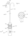
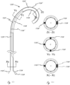
- FIG. 1A illustrates an exemplary embodiment of a system that integrates steering and a medical device.
- System 1000 includes handle assembly 1002 and steering and medical device portion 1004.
- Steering and medical device portion 1004 includes a proximal portion 1006 and steerable portion 1008.
- the system is adapted so that handle assembly 1002 can be actuated to cause steering of the steerable portion 1008, and optionally can be further actuated to cause movement of medical device 1010 relative to steering and medical device portion 1004.
- handle assembly 1002 includes first actuator 1001, second actuator 1003, and third actuator 1005.
- First actuator 1001 is adapted to be actuated (in this example rotated) relative to handle body 1007 to cause the steering of steerable portion 1008, and specifically steering outer sheath 1102.
- Steerable portion 1008 in this embodiment can be steered, or bent, into the configuration shown in Figure 1A in solid lines, and can also be steered into the configuration shown in dashed lines, or anywhere in between, and in some embodiments the opposite steering function is limited to simply straightening the shaft from an initial bent configuration, such as the solid line bent configuration in Figure 1A .
- the term "steer” in this disclosure means to deflect or bend, optionally via actuation of at least one pull wire, but in some instances the term can include shaft rotation (torqueing) and axial movement.
- pull wire herein refers to any element that may transmit a tensile force from the proximal end of the device to the distal end region.
- Pull wires may be comprised of metal wire such as stainless steel or nickel titanium, either solid or stranded/braided, or it may be comprised of a polymer such as aramid fiber (Kevlar ® ), polyethylene, ptfe, eptfe, etc., preferably stranded/braided, but also in monofilament form.
- the pull wire is constructed from an aramid fiber bundle having four 50 denier multifilament (approximately 25 filaments) threads braided together at a high picks per inch.
- the wire cross-sectional diameter is typically in the .005"-.012" range, more preferably .008"-.010", although braided or stranded wire may flatten or ovalize in the device lumen.
- the preferred construction embodiments are believed to provide optimized strength and wear resistance for the size necessary to keep the shaft diameters to a minimum.
- Optional second actuator 1003 is adapted to be actuated relative to handle body 1007 (in this example rotated) to cause rotation of medical tool 1010 relative to shaft 1102 (labeled as rotation movement "R")
- optional actuator 1005 is adapted to be actuated relative to handle body 1007 (in this example axially) to cause axial (distal-proximal) movement of medical device 1010 relative the outer sheath 1102.
- Proximal portion 1006 is not configured to bend significantly when steerable portion 1008 is steered (bent/deflected), although the proximal portion may flex and bend to conform to the anatomy within which it is used. In many embodiments, this is accomplished by constructing the steerable portion 1008 from a softer or less rigid material and/or composite construction than the proximal portion 1006.
- FIG. 1A is an example of an apparatus that includes an integrated handle assembly that is in operable communication with both a steerable outer shaft and an inner medical tool.
- the handle assembly is integrated in that it is assembled and constructed to be in operable communication with the outer shaft and the inner medical tool prior to packaging and use.
- "Integrated" as that term is used in the context of an integrated handle assembly refers to a handle assembly in which at least one part of the handle assembly has to be broken or taken apart before the medical tool can be removed from within the outer shaft.
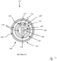
- Figure 1B illustrates an exemplary cross section A-A (shown in Fig. 1A ) of the steering and device portion 1004, and specifically in the steerable portion 1008.
- medical device 1010 is sized and configured to be disposed within a steerable sheath.
- the steerable sheath includes an outer shaft 1102 and a set of pull wires 1104, which are axially fixed in a distal region of steerable portion 1008.
- the medical tool in Figures 1A and 1B can be, for example, any medical tool herein, such as an ultrasound tool.
- ultrasound probe When “ultrasound probe” is used herein, it generally refers to an elongate tool that includes at least one ultrasound transducer and one or more conductive elements that electrically connect the at least one ultrasound transducer to a proximal region of the elongate tool.
- a proximal region of the ultrasound probe includes, or is modified to include, at least one proximal contact, which is in electrical communication with the at least one ultrasound transducer, and which can be put into electrical communication with, optionally via attachment to, an electrical contact on another device, cable, or connector.
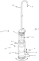
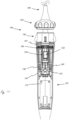
- Figure 2 illustrates an exemplary system 10 that is adapted to function similarly to the system in figures 1A and 1B , and also illustrates exemplary internal components of handle assembly 12 (internal components shown as dashed lines).
- Handle assembly 12 is integrated and in operable communication with outer steerable shaft 20 and medical tool 30.
- Handle assembly 12 includes actuator 14 that is adapted to, when actuated relative to handle body 15, cause steering of steerable shaft 20.
- Actuator 14 is in operable communication with steerable shaft 20 via steering control 16 disposed in handle assembly 12.
- Medical tool 30 includes a proximal portion 18 disposed within and incorporated into handle assembly 12.
- Actuator 13 is in operable communication with medical tool 30, and actuation of actuator 13 (in this example rotation) relative to handle body 15, causes rotation of medical tool 30 relative to outer shaft 20 via rotation control 1215.
- Optional third actuator 17 is also in operable communication with medical tool 30, and is adapted to be actuated, in this embodiment, axially (relative to handle body 15), to cause axial movement of medical tool 30 relative to outer steerable shaft 20 via axial control 1217.
- the medical tool in Figure 2 can be, for example, any medical tool herein, such as an ultrasound tool.
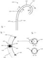
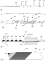
- Figures 3A-3E represent exemplary embodiments of a distal region of the sheath portion 1208 of steerable sheath 1202 in system 1200.
- the illustrated cross-sections show only the outer sheath 1208 and not the inner tool 1212.
- the outer sheath 1208 preferably has a composite construction to improve torque transmission applied to the outside of the shaft from the proximal end, or to resist torque forces applied to it from within the shaft, such as from tool 1212.
- multiple braid elements 1250 preferably formed from metal wire (round, pairs of round, or ribbon shaped) and/or multiple fibers (e.g., aramid or nylon), may be braided directly over a thin wall (e.g., .0010" ⁇ .0005") lubricious liner tube 1251, such as a PTFE or FEP material.
- a thin wall e.g., .0010" ⁇ .0005"
- lubricious liner tube 1251 such as a PTFE or FEP material.
- thermoplastic polymer 1252 (such as Pebax in a range of durometers from 25D-72D, or nylon, or other common catheter materials) may be laminated with heat using heat shrink tubing (such as FEP) to reflow the polymer over the braid elements 1250 and liner tube 1251 to form a uniform member.
- the thermoplastic polymer 1252 may also have radiopaque compounds that include materials such as bismuth, barium sulfate, or tungsten in order that the tip of the sheath be visible to the user under fluoroscopy.
- the pull wire 1104 is preferably parallel to the central access in the steerable (deflectable) portion 1222 of the sheath and also preferably provided in a lumen 1253 created within the wall of the steerable sheath 1208.
- This lumen may be created during the thermoplastic polymer tubing extrusion process or during a shaft heat lamination fusing process with the aid of a removable mandrel.
- the pull wire lumen 1253 may further be created by incorporating a pull wire tube 1254, preferably temporarily supported by a removable mandrel, within the wall.
- the removable mandrel may also be placed alongside the pull line 1104 or 1104' during the fusing process, resulting in a somewhat ovalized lumen 1253 within which a fiber pull wire may be allowed to flatten into, allowing space for free movement of the pull wire.
- the tube 1254 may include PTFE, FEP, polyimide, or another material which maintains its wall integrity during a heat lamination process up to approximately 500 °F.
- the tube is preferably surrounded and supported by the thermoplastic polymer 1252 which is preferably heat laminated against the tube.
- the pull wire lumen preferably comprising the pull wire tube, is incorporated within the weave of the braid elements 1250.
- braid elements 1250 running in one direction would pass under the pull wire lumen, while those running in the opposite direction would pass over the pull wire lumen.
- the braid reinforcement provides a more dimensionally stable lumen during catheter manipulations and also helps assure the straightness of the lumen as needed.
- the pull wire Proximal to the steerable portion, the pull wire may continue proximally parallel to the central axis on the same side of the outer sheath 1208, such as is illustrated in Figure 3Ai-iii .
- an additional pull wire 1104' within an additional pull wire lumen routed within the wall of sheath 1208, up through the steerable portion 1222, may be required to straighten the steerable portion of the device.
- This straightening pull wire 1104' is preferably routed within steerable portion 1222 on the side opposite from the pull wire(s) 1104 used for steering (deflection) in the steerable portion 1222.
- two lumens and two straightening pull wires 1104' could be used, essentially mirroring the paired 1104 pull wire configuration.
- These straightening wires could also be constructed to allow deflection in the opposite direction by tensioning a greater distance (beyond just straightening) within the handle.
- a portion 1223 of the distal catheter just proximal to the steerable (deflectable) portion 1222 may be forced to conform to a curve based on the constraints of the anatomy in which it is used. For a specific embodiment where the device is advanced into the heart chambers from a groin access, the portion 1223 forced into a curve is expected to range from 5 to 25 cm in length.
- torque is transmitted through this distal curved region 1223 to the catheter tip.
- a non-uniform cross section and/or tension of the device in this region 1223 may induce a tendency for the shaft to build up and suddenly release torque, causing a "whip" or sudden jerk in rotation as it is torqued.
- the pull wire 1104 may spiral around the central axis of the sheath in at least the curved region 1223 proximal to portion 1222.
- the pull wire of this embodiment may make a full circumferential wrap over approximately 10 cm of length, with this value ranging 5-15 cm.
- the spiral may only need to be present in the curved region 1223, continuing straight proximally thereafter through proximal portion 1224 (similar to 1006), which may minimize the friction in the pull wire lumen and the associated pull wire force required to steer (deflect) the steerable portion 1222.
- the spiral may also make a minimum of one turn before continuing straight, or spiral the full length of the shaft.
- it may only be necessary to distribute the pull wire tension to opposite sides of the shaft.
- deflection of the steerable section 1222 is accomplished with two parallel pull wires 1104 positioned adjacent one another on the same side of the sheath 1208.
- the pull wires are routed to opposite sides of the shaft, each 90° from the position in the steerable section 1222, to distribute the tension more evenly.
- any plurality of pull wires could be routed in the same configuration as illustrated in Figures 3B or Figure 3C , with the multiple proximal pull wires distributed uniformly around the shaft circumference.
- the pull wires 1104 may be routed proximally along the opposite sides of the shaft for most of the shaft proximal portion 1124 length, but preferably brought back together adjacent one another near the proximal end portion of the shaft to allow the wires to exit the same side of the proximal shaft together to facilitate them being secured together to a handle component for simultaneous actuation tension.
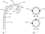
- Figures 3Di-iv illustrate another embodiment of the distal region of catheter with construction similar to that previously described, but instead configured to provide a distal steerable portion 1222 which can be deflected into two different directions.
- a two pairs of pull wires 1105/1107 and 1106/1108 are along the proximal shaft region 1224 and curved region 1223.
- This is similar to Figure 3Ai-iii , except that the wires are paired on each side of the shaft.
- the routing could also be spiraled as in Figure 3Bi-ii , or other configurations discussed.
- the wires are routed 90° from the proximal portions, although other angles are contemplated.
- one or more of the pull wires may be terminated and anchored to the shaft, with the remaining pull wires (e.g., 1106 and 1108) continuing to a more distal tip location 1226 where they are anchored.
- This configuration allows independent actuation of pull wires terminated at 1225 and 1226 such that different shapes may be created during actuation.
- Figure 3Dii shows both lines 1107 and 1108 tensioned to create a variable curve in the same direction.
- Figure 3Diii shows lines 1107 and 1106 tensioned to create an "S" curve. Other configurations are also possible.
- the pull wires (such as 1104 and 1104') must be terminated at their distal end in a manner that reliably affixes them to the wall of the distal steerable shaft portion 1222, such that they do not break or pull free under repeated applications of tension.
- the pull wires 1104 and 1104' upon exiting the distal pull wire lumen 1253, are circumferentially interwoven into the braid wires 1250 of the distal shaft 1222 (shown without the thermoplastic polymer 1252).
- One or more of the pull wires 1104 or 1104' may also be additionally or instead wrapped and/or tied around the outside of the braid wires 1250 for additional securing.
- the braid wires 1250 may be then trimmed distal to the securing point, with the interwoven and/or wrapped pull wires preventing the braid wires from expanding and/or unraveling. Additional adhesives such as UV cured or cyanoacrylates may also be used to secure the pull wires to the braid wires.
- the weave and/or wrap of the pull wires and braid wires is then laminated with a thermoplastic polymer which melts within the space around the wires and cools to secure them in place.
- the thermoplastic polymer may also have radiopaque compounds that include materials such as bismuth, barium sulfate, or tungsten in order that the tip of the sheath be visible to the user under fluoroscopy.
- the tool 1212 may also or alternatively be constructed with one or more pull wires to deflect the tip in a manner similar to any of the previous embodiments described for the outer sheath 1208.
- the pull wires could be routed next to the conductors inside the lumen of the tubular element 1212. Actuation of the pull wires could be from an actuator located in the proximal handle 1206.
- the distal shaft of tool 1212 may also be formed into a particular shape (e.g., an arc) such that it bends into the shape as it exits the tip of the steerable portion 1222 of outer sheath 1208.
- the stiffness of the distal shaft of tool 1212 is such that it does not substantially deform outer sheath 1208 while inside, but upon exiting is allowed to bend.
- the shape may be set by any one or combination of the following means: heat setting the polymeric material, using a moveable or fixed shaped stylet within the inner lumen of shaft 1212 or within a lumen within the wall of shaft 1212.
- a stylet could be round, oval, or rectangular in cross section, and be formed of stainless steel, nitinol, or a rigid polymer such as PEEK, Vestamid, or similar.
- the outer steerable sheath could alternatively be made to bend with a similar method as above, with or without additional pull wire deflection, and with or without additional shape or deflection of the distal portion of tool shaft 1212.
- One aspect of the disclosure includes methods of disassociating at least a portion of the system from other components, optionally as part of a reposing process.
- the medical tool includes one or more electrical contacts that are coupled to other electrical contacts, which are in electrical communication with an energy console, and examples of consoles are known in the ultrasound art.
- Figure 4 illustrates merely a portion of an exemplary medical tool, such as an ultrasound probe, that can be electrically coupled directly or indirectly to an energy console, such as an ultrasound console.
- Reposing the device can involve disconnection of one or more proximal electrical contacts and moving the tool portion distally out of the distal end of the sheath portion.
- tool portion 1212 comprises at least a tool outer sheath or member 2010, distal working end 1821 (which can include at least one ultrasound transducer), and conductor bundle 2020.
- the conductor bundle 2020 extends from the distal working end 1821, through the tool outer member 2010 to a proximal connector (the connector and handle mechanism are not shown in Fig. 18 for clarity).
- the medical tool is used for ultrasound imaging, optionally where the distal working end 1821 comprises a two-dimensional (2D) array of piezo electric components mounted on an ASIC (application specific integrated circuit).
- ASIC application specific integrated circuit
- Figure 5 illustrates a merely exemplary proximal end of a medical device (the medical device is shown on the right), and in this embodiment the medical device is an ultrasound probe.
- the proximal end 2015 of the medical device is adapted to be electrically coupled to connector cable 270, which is directly or adapted to be indirectly electrically coupled to an energy console, such as an ultrasound energy console.
- conductor bundle 2020 extends from a distal region of the medical tool (distal region not shown) into a proximal connector 2015 within which is housed a rigid or flexible printed circuit board (“PCB”) 2030.
- the connector bundle 2020 includes a plurality of contacts 2024 (examples of which are described below) that are attached to PCB board contacts 2031.
- Each individual trace from each contact 2031 is linked to individual exposed contacts 2050 on another portion, optionally more proximal, of the PCB.
- the individual PCB traces may also pass through other useful circuitry on the PCB.
- the exposed contacts 2050 are configured for a mechanical mating for electrical conduction to similar contacts 2060 on mating connector cable 2070, similar in concept to the proximal tool connector 1990 described previously, which links the tool 1204 to a user-interface console.
- Proximal connector 2015 can be incorporated into any of the systems, handles, steerable sheaths, medical tools, etc., herein.
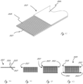
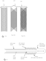
- Figures 6A and 6B illustrate an exemplary conductor strip (also referred to herein as a flexible circuit strip) 2021 that can be included in any of the conductor bundles herein.
- the embodiment in Figures 6A and 6B is an example of a conductor strip that can be included in bundle 2020 from Figures 4 and 5 .
- the embodiment in Figures 6A and 6B can be incorporated into any other system herein.
- conductor bundle 2020 comprises a plurality of flex circuit strips, including multi-trace strips 2021, as well as conductive strips for grounding 2022 and shielding 2023 (only a portion of which are shown).
- Each multi-trace strip comprises a plurality of conductive traces 2025, which can be seen clearly in Figures 6B , 6C and 6D .
- the number traces 2025 in Figures 6D-G is twelve, and the number of traces in Figures 6A-6C is sixteen, and they are both exemplary as to the number of traces 2025 that can be used.
- Each strip 2021 can be approximately .072" wide and .0022" thick, and can optionally comprise sixteen .0022" wide x about.0007” thick conductive (e.g., copper) traces, each spaced approximately .0022" apart.
- the traces are disposed on an insulating substrate layer 2027, such as a polyimide substrate, and the traces can be at least partly covered by a cover layer 2026, such as a photoimageable film cover (“PIC”) layer or other dry film solder mask (DFSM) or other similar material.
- PIC photoimageable film cover
- DFSM dry film solder mask
- the strip 2021 is approximately .055" wide and comprises twelve conductive traces (see figures 6D-G ). In other embodiments, the strip 2021 is approximately .037" wide and comprises eight copper conductive traces.
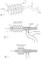
- the outer strips 2022 and 2023 used for grounding and shielding may have a similar construction and dimension except they can comprise a single full width strip of copper. As optimized for a 2D piezo array, a stack of approximately seven 16-trace strips 2021 would be required (or nine 12-trace, or fourteen 8-trace), along with one each of strips 2022 and 2023 on each side of the stack of multi-trace strips.
- Figure 6E illustrates a portion of an exemplary bundle 2020 with nine strips 2021 stacked together.
- Figure 6F illustrates a portion of the bundle that includes nine strips 2021 stacked, as well as ground strip 2022 and shield strip 2023 (only those on top are labeled).
- the complete bundle may optionally be held together with a, for example without limitation, about.001" wall thickness shrink tube, such as the tubing 2028 in Figure 6G .
- the flex circuit dimensions and number of traces discussed above are for a particular configuration of a piezo-electric array (and/or an ASIC controller thereof) and may be varied depending on how the number and size of array elements are optimized for the particular application.
- each flex circuit strip has the conductive material (e.g., gold-plated copper) exposed over a length of approximately, for example, 3mm through removal of the cover layer 2026 at location 2024.
- Location 2024, and other exposed locations described herein, is generally referred to as a "contact.” It is understood that when used in this context, the contact actually includes a plurality of separated conductive traces (such as shown in region location), each of which is adapted to be in electrical communication with its own corresponding conductive element. "Contact” is therefore not limited to mean only a single electrical connection between two conductive elements.
- FIG. 6A shows a plurality of exposed regions 2024, the embodiment in Figure 6A will first be described herein as if there is only one exposed region (i.e., region 2024 at the proximal end).
- the strip 2021 can be made to create an electrical connection to matching exposed contacts 2031, shown in Figures 6A-C , for conductive traces on the PCB 2030.
- sixteen individual traces, sized and spaced to match sixteen traces in the multi-trace strip 2021 would be provided within a given contact 2031.
- An ACF anisotropic conductive film
- soldering conductive adhesive
- mechanical connection or any combination of these may be used to achieve a suitable electrical connection (electrical coupling) between the strip traces and the PCB contacts.
- Figure 7 illustrates the integrated system 1200 of the steerable sheath 1202 and medical tool 1204 wherein the system 1200 is connected to console 4000 via the connector cable 2070.
- the tool 1204 comprises a proximal connector 2015 which forms a mating connection to cable 2070.
- repose e.g., reprocess and reuse
- a crypto-authentication chip (crypto-chip) is incorporated into the tool 1204, preferably on the PCB 2030, although other locations, such as within the steerable handle 1206, or within the tip 3000, are contemplated.
- the crypto-chip is programmable only by the original manufacturer who controls the authentication keys.
- the console 4000 to which the system 1200 is connected has a Trusted Platform Module (TPM) which also has the authentication keys.
- TPM Trusted Platform Module
- the console 4000 is able to authenticate the system 1200 via the crypto-chip and as desired may read and write information to the chip (e.g., via an EEPROM feature).
- RFID chips preferably encrypted, may be used to read and transmit data between the console, connector, and the device.
- cleaning can refer to any type of cleaning, such as without limitation: cleaning an interior of an outer shaft using a flushing system of cleaner and/or disinfectant and optionally mechanical scrubbing with small brushes; mechanical cleaning (e.g., wipes, brushes) an outer portion of an outer shaft and/or outer portion of a medical device shaft (e.g., ultrasound probe) with a cleaner/disinfectant, and optionally submerging the shaft in an ultrasound bath of cleaner/disinfectant for a specified period of time; and optical cleaning methods such as comprising using UV light.
- cleaning as used here does not refer to a specific cleaning process, but rather refers to the general idea of cleaning an object.
- the disclosure herein also includes methods of assembling or reassembling any of the subassemblies or assemblies herein, including any of the subassemblies within any of the handle assemblies herein.
- the disclosure here includes methods of spooling one or more pull wires over a bearing surface in a spindle support and then around the spindle.
- the methods herein also include manufacturing or constructing any of the individual components of any of the subassemblies or assemblies herein.
- the disclosure includes methods of manufacturing handle shell components that have particular configurations (e.g., guides, walls, etc.) that can accommodate the internal parts that allow the assemblies or subassemblies herein to function as intended.
- any of the handle assemblies, medical tools, steerable sheaths, and electrical connections herein can be used together in a system in any combination with each other.
- any of the technology, including ultrasound and steering technology, in any of the following U.S. patent references may be incorporated into any of the medical tools, devices, systems, or methods of use thereof herein, the disclosures of which are incorporated by reference herein: 6100626, 6537217, 6559389, 7257051, 7297118, 7331927, 7338450, 7451650, 7451650, 7527591, 7527592, 7569015, 7621028, 7731516, 7740584, 7766833, 7783339, 7791252, 7791252, 7819802, 7824335, 7966058, 8057397, 8096951, 8207652, 8207652, 8213693, 8364242, 8428690, 8451155, 8527032, 8659212, 8721553, 8727993, 8742646, 8742646, 8776335, 8790262, 8933613, 8978216, 8989842, 9055883, 9
- Figures 8A and 8B illustrate a merely exemplary handle assembly that can be in operable communication with elongate body 117 and elongate inner body 110.
- handle assembly 120 includes handle body 123 that has an outer surface that can be gripped by a user, first actuator 121, and second actuator 122.
- Actuator 121 can be in operable communication with elongate body 100
- actuator 122 can be in operable communication with elongate inner body 110.
- Actuator 121 is adapted to be both rotated and moved axially relative to handle body 123 (and relative to second actuator 122). This allows actuator 121 to cause axial movement of the medical tool 103 and rotation of the medical tool 103 relative to a distal end of elongate inner body 110.
- Second actuator 122 is adapted to be actuated (e.g., rotated in this embodiment) relative to handle body 123 to cause deflection of the elongate inner body 110.
- the handle assembly can have internal components that interface with proximal ends of tensioning members (e.g. tensioning members 111, 112 and 116) such that actuation of actuator 122 tensions one or more tensioning members to cause deflection of the elongate inner body, and thus also the medical tool.
- actuator 121 is distal to actuator 122, but in other designs their relative positions could be reversed.
- Figure 8B shows handle assembly 120 after actuator 121 has been advanced distally relative to its position in figure 8A . This distal advancement causes the outer elongate body 100 to be advanced distally, and thus causes the medical tool to be advanced distally. Actuator 121 can similarly be retracted proximally relative to its position in figure 8B .
- actuator 121 could be in operable communication with elongate inner body 110 and actuator 122 can be in operable communication with elongate body 100.
- Slack can be added to the one or tensioning members (e.g., pull wires) in the handle assembly to better allow the outer elongate body translate relative to the elongate inner body.
- tensioning members e.g., pull wires
- the outer shaft can be moved axially relative to the inner deflectable shaft.
- the outer shaft can be constructed with sections of materials that vary in stiffness (e.g., durometer) along the length of at least a portion of the outer shaft. For example, a first portion that is distal to a second portion can have a lower durometer than the second portion. Because the outer shaft can be moved axially relative to the deflectable inner shaft, and because the stiffness of the outer shaft can vary along its length, the deflection, including the degree (or amount), of the overall device can be selectively controlled by controlling the axial position of the outer shaft (relative to the inner shaft). Axial movement of the outer shaft can thus selectively control deflection of the device.
- stiffness e.g., durometer
- a user e.g., physician
- sections of varying stiffness in the outer shaft can allow for more or less deflection depending on the relative position of the outer shaft relative to the deflectable inner shaft. For example, deflecting the inner shaft at a region where the outer shaft has a relatively higher stiffness can result in less deflection than when the inner shaft is deflected at a region where the outer shaft has less stiffness.
- Figure 9C shows exemplary apparatus medical apparatus 130, which includes elongate inner body 132 (see figure 9A ) and elongate outer body 131 (see figure 9B ).
- Figure 9D illustrates Section A-A shown in the assembly in figure 9C , which is a section in the deflectable section of the device. Parts from figures 9A-9C are similarly labeled. As can be seen in figure 9D , tensioning members 111 and 112 are very near to one another and about 180 degrees away from straightening tensioning member 116.
- elongate inner body 110 includes two layers of braided material 119, and the tensioning members are, at least at the location of this section, essentially sandwiched between the two layers of braided material.
- the two layer of braided material canm be the first and second layers in figures 21A-21C , for example.
- Annular spaces 118 allow freedom of movement and space for optional lubricant.
- Inner body 110 may be made from, for example without limitation, a polymeric material such as Pebax, optionally with a lubricious additive.
- Inner body 110 may include liner 125, such as a PTFE liner.
- the cable bundle 105 may be surrounded by one or more layers of insulation 126, such as PTFE insulation.
- Outer member 100 may comprise a polymeric material 127, such as Pebax. Outer member 100 may also include a radially inner liner 128, such as a PTFE liner. Any of the pullwires (e.g., 111, 112, 116) may be disposed in a lumen with a liner, such as PTFE liner 129.
- Medical apparatus 130 (or either of elongate body 132 and elongate body 131, individually) can be in operable communication with any of the handle assemblies herein, including handle assembly 120 shown in figures 8A and 8B .
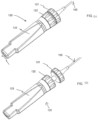
- Figures 10A , 10B , 10C , 10D and 10E illustrate an additional exemplary handle assembly that can be in operable communication with any of the medical devices, including ultrasound probes, herein.
- the exemplary handle assembly shown in figures 10A -10E can be coupled to (directly or indirectly) and in operable communication with medical apparatus 130 shown in figures 9A-9D .
- both elongate outer body 131 and elongate inner body 132 are coupled to and in operable communication with the handle assembly shown in figures 10A -10E.
- the handle assembly in figures 10A -10E has some similarities to the handle assemblies, the individual components, and subassemblies that are shown in figures 8A and 8BB. Unless indicated to the contrary, concepts, features and methods of use from figures 8A and 8B that can be incorporated into the handle assembly in figures 10A -E are hereby incorporated by reference for all purposes into the disclosure of the handle assembly shown in, and described with respect to, figures 10A -E. Similarly, concepts, features and methods of use that are shown in, and described with respect to, figures 10A -E that can be incorporated into other handle assemblies herein are hereby incorporated by reference for all purposes into the disclosure of any of the handle assemblies set forth herein.
- Figure 10A is side view of handle assembly 140 with a portion of handle body 141 removed so that some internal components of the handle assembly can be seen.
- Handle assembly 140 includes first actuator 143 and second actuator 142, and in this embodiment first actuator 143 is distal to second actuator 142.
- First actuator 143 can be both moved axially and rotated relative to the handle body and relative to a second actuator (in this embodiment actuator 142).
- First actuator 143 is in operable communication with an outer elongate body, such as outer elongate body 131 ( see figure 9B ).
- Axial movement of actuator 143 causes axial movement of the outer elongate body, while rotation of actuator 143 causes rotation of the outer elongate body.
- Second actuator 142 is in operable communication with an inner elongate body, such as inner elongate body 132 ( see figure 9A ). Actuation of second actuator 142, in this embodiment rotation, causes deflection of the inner elongate body.
- a rotatable and axially movable actuator i.e., first actuator 143 is in operable communication with an outer elongate body.
- First actuator 143 is coupled to elongate outer body movement assembly 150 shown in the exploded view in figure 10B , such that movement of first actuator 143 causes movement of assembly 150.
- Elongate outer body movement assembly 150 is similarly coupled to the elongate outer body so that movement of first actuator also causes movement of the elongate outer body.
- the outer elongate body is attached to removable part 153 after it is inserted into channel 156.
- Removable part 153 and channel 156 are configured so that removable part 153 is constrained by at least one inner surface of channel 156 when it is inserted therein.
- Elongate outer body movement assembly 150 also includes a distal head portion 151 that is secured to first actuator.
- Elongate outer body movement assembly 150 also includes a rotation limiting mechanism similar to that which is described herein, which limits the rotation of first actuator 143, and thereby limits the rotation of the outer elongate body. Any of the disclosure above related to rotation limiting subassemblies, functionality, and use, is incorporated into this embodiment for all purposes and may be incorporated into this and similar designs.
- part 157 (see fig. 10B ) interacts with part 161, and part 162 interacts with part 158.
- the physical interactions of these two sets of parts limits rotation to the desired rotation limit, e.g., such as limiting rotation up to 630 degrees of rotation of the outer body (in other embodiments the allowed rotation could be more than 630 degrees, such as up to and including 720 degrees).
- removable part 153 can be detached from the outer elongate body to allow the outer elongate body to be removed from the handle assembly and cleaned, before being reinserted and reattached to removable part 153 or a new removable part if part 153 is damaged or broken.
- Handle assembly 140 also includes inner elongate body deflection assembly 146, which is in operable communication with second actuator 142.
- Inner elongate body deflection assembly 146 includes central gear 147 adapted and configured to rotate when second actuator 142 is rotated. Central gear 147 interfaces first spindle 148 and second spindle 149 via a geared interface, such that rotation of central gear 147 causes rotation of the spindles in the opposite direction.
- the inner elongate body deflection assembly 146 including the spindles, extends further proximally than the elongate outer body movement assembly 150.
- the inner elongate body extends through the outer elongate body and extends further proximally than the outer elongate body within handle assembly 150. This allows one or more pullwires that are part of the inner elongate body to extend radially outward and interface with reels 160.
- elongate outer body movement assembly 150 allows for the inner and outer elongate bodies to be independently controlled by first actuator 143 and second actuator 142.
- Handle assembly 150 also includes printed circuit board (“PCB”) 170 disposed within handle body 141, the PCB being in electrical communication with a cable bundle, such as cable bundle 105 in figure 53, or any of the cable bundles herein that are in communication with the medical tool, such as an ultrasound transducer.
- PCB printed circuit board
- Handle assembly 150 also includes a rotation indicator 180 that can be used to show a user the extent to which at least one of the first actuator and the second actuator are rotated relative to a home, or neutral position.
- First actuator 143 can include a rotation indicator 181 that is aligned along an axis with rotation indicator 180 when first actuator 143 is in a neutral position, as shown in figure 11 .
- rotation indicator 181 is rotated relative to the axis along which rotation indicator 180 extends, which enables the user to visually understand that first actuator 143, and thus the elongate outer body, is rotated to some extend relative to the neutral position.
- second actuator 142 can also have rotation indicator 182 that is aligned along an axis with rotation indicator 180 when second actuator 142 is in a neutral position, as shown in figure 11 .
- rotation indicator 182 is rotated relative to the axis along which rotation indicator 180 extends, which enables the user to visually understand that second actuator 143, and thus the elongate inner body, is deflected to some extent relative to its neutral position.
- the handle assembly can include one or more sensors to track how much rotation has occurred for the outer elongate body, or how much deflection has occurred in the inner elongate body.
- the handle assembly can include an encoder for each actuator.
- the device can include one or more lubricants between the inner and outer elongate bodies to make it easier to move the inner and outer elongate bodies relative to one another by reducing friction between the two. If the medical device needs to be cleaned for reuse, additional lubricant can be added between the inner and outer elongate bodies after the cleaning process.
- a physician may not want to have to hold the handle at all times, but may want the handle to stay in a particular position relative to a patient.
- a medical tool is an imaging tool (e.g., an ultrasound imaging tool)
- the physician may not want the tool to rotate or move once it is a desired position, in order to maintain a particular imaging field of view.
- a physician may simply place the handle across a portion of the patient's body, but the handle may move once placed down on the patient.
- Figure 12A illustrates an exemplary handle stabilization member 190 (a handle stabilization member may be also be referred to herein as a handle stabilization apparatus) that can provide any of the functions or benefits just listed, such as at least one of the following, stabilize a medical device handle relative to a part of a patient, minimizing movement of the handle relative to a part of the patient, etc.
- a handle stabilization member may be also be referred to herein as a handle stabilization apparatus
- Handle stabilization member 190 includes handle receiving guide 191 and patient interface region 192, and optional stabilization assist region 193.
- Guide 191 can be configured with any configuration to allow it to stably interface with a portion of a handle, such as the merely exemplary handle portion 195 in the exemplary handle assembly shown in figure 12B .
- guide 191 has a curved configuration to interface with the curved configuration of handle portion 195.
- the curved configuration is U-shaped, but it could be any other curved shape, such as C-shaped, or any other difficult to define curved configuration.
- the guide may also be configured with any curvilinear configuration that can stably interface with a portion of the handle.
- the guide can alternatively have solely flat surfaces (e.g., partial square or partial rectangle).
- the guide can be configured to prevent handle movement in at least one direction (e.g., side to side, proximally-distally, etc.).
- the constraint on handle movement may also depend on the configuration of the handle.
- guide 191 is configured as a channel, and is adapted to prevent side to side movement while allowing a handle to be lifted upward out of the open region. If a true cylinder handle were placed in guide 191, the cylinder could also move proximally or distally in the guide 191.
- a handle portion, such as handle portion 195 in figure 12B can be configured with one or more movement limiting regions 196 and 197 that can further limit or minimize handle movement when interface with the guide 191.
- movement limiting regions 196 and 197 have larger outer dimensions than the central region in between, so that when handle portion 195 is placed in guide 191 from above, region 197 prevents pure distal movement of the handle, and region 196 prevents pure proximal movement, because of their relatively larger dimensions.
- the handle could alternatively have only one movement limiting regions, or more than one.
- the central region between regions 196 and 197, as well as the guide 191, can be sized so that handle portion 195 and guide 191 interface with an interference fit.
- Stabilization member 190 includes region or portion 192 that is configured to interface with, and optionally conform to, a portion of the patient.
- portion 192 interface with and conform to a patient's leg, but it could have any other configuration so that it interfaces with and conforms to any other surface (e.g., arm, torso, wrist, etc.).
- Portion 192 can be a rigid material manufactured with the configuration shown, or it can be a flexible material that can more easily conform to a variety of patients.
- portion 92 could be a polymeric material that has enough stiffness to maintain the position of member 190 when placed on a patient, but flexible enough to be deformed when not in use, such as rolling up to save space in packaging and/or storage.
- portion 192 can be manufactured so that it more naturally assumes a configuration of the portion of the patient on which it will be placed.
- portion 192 can be flexible/foldable, but can have a natural tendency to revert or assume a curved configuration, such as the curved configuration shown in figure 12A .
- Exemplary configurations of portion 192 include general U-Shape, C-shape, etc, which may facilitate better conformability to legs and arms.
- Portion 192 can also be rigid and non-deformable, and can be manufactured with any desired configuration.
- Stabilizing member 190 also includes optional additional stabilization assist portion 193, which in this exemplary embodiment can act as a counter weight to guide section 191, where the handle will be placed.
- Stabilization assist portion 193 can have any desired shape, configuration, and/or material that provides the desired weight to counteract the weight of the handle in the guide. Portion 193 is optional and may not be needed. In some embodiments, portion 193 can be made of a different material that provides the counter weight functionality.
- portion 193 is shown on one end of the stabilization member 190, with guide 191 on the other end, and patient interface/conforming portion in between the two.
- Figure 12B illustrate an exemplary handle assembly, which is configured to be used with the exemplary handle stabilization member in figure 12A .
- Other handles can be used with stabilization member 190.
- Figure 13 illustrates an exemplary handle stabilizing apparatus that is similar to that shown in figure 12A .
- the apparatus in figure 13 like the apparatus shown in figure 12A , includes a body member 201 with at least one handle guide 202, the handle guide having at least one surface that is configured to interface with at least a portion of a medical device handle to provide stability to the handle in at least one direction.
- the handle guide may optionally include magnetic material to help stabilize the handle.
- the handle guide 202 may optionally include a weighted region at the bottom help stabilize the body member.
- the body 201 in figure 12 includes an elongate channel guide 202, which is shown.
- the channel has a constant width along its length, but in other embodiments the channel may have a width along its length that is not constant, optionally having a greater width at a first channel end than at a second channel end.
- the optional weighted region (e.g., at the bottom) can bias the body to a natural position on a flat surface so that when its position relative to the flat surface is changed in response to a force, it is biased to return to the natural position when the force it removed.
- the handle guide or body 201 in figure 13 can include any of the features of any of the handle guides or handle guide regions described herein. In use, the handle guide apparatus in figure 13 or any alternative thereof can be interfaced with a medical device handle to increase the stability of the handle.
- the embodiment in figure 13 is an example of a medical device handle stabilizing apparatus, comprising a body 201 including an elongate and recessed handle guide 202, the recessed handle guide including a recessed channel configured to interface with an elongate handle portion of a medical device to provide stability to the handle portion in at least one direction, the body 201 being biased to an upright at-rest position when positioned on a flattened surface, the recessed handle guide facing upward when the body is in the upright position.
- Body 201 can include a weighted bottom region and a curved bottom surface, the weighted bottom region and the curved bottom surface biasing the body to the upright at-rest position.
- a medical device handle can interface with a separate stabilizing apparatus as in figures 12A and 13 , although a handle can alternatively or in addition to incorporate one or more features that provide for increased handle stabilization.
- Figures 14-17 illustrate such exemplary handles.
- the handle includes a capture mechanism configured and adapted to capture an article that is placed relative to a patient during a medical procedure, optionally wherein the article is an article draped over the patient.
- Figures 14-17 illustrate exemplary handles that include one or more capture mechanisms.
- Figure 14 illustrates a capture mechanism that includes first and second portions that are configured to interface with the article and capture the article between the first and second portions. The second portion in this embodiment in movable relative to the first portion, and can optionally be biased to return towards a home position, such as by being spring-loaded.
- Figure 15 illustrates first and second capture mechanisms of a handle, e.g., two clips which may be adapted to swivel relative to the main handle body.
- the one or more capture mechanisms can be disposed on a proximal portion of the handle, such as in figures 14-17 .
- the embodiments in figures 14-17 are examples of a medical device, the medical device including an elongate handle housing 203, and an object capturing member (e.g., 205, 206, 207, 208) secured relative to the handle housing, the object capturing member including a movable member (e.g., 204, 206) that is movable relative to the handle housing from an open position to a closed position, wherein in the closed position (such as shown in figure 14 ) the movable member is closer to a first portion of the handle than in the open position.
- object capturing member 205 comprises flexible teeth adapted for capturing an article of clothing.
- the moveable member e.g.
- the movable member 204, 208, 207) may optionally be spring loaded (biased), such as for varying thickness of an article of clothing or garment.
- the movable member can be biased to return towards the closed position from the open position.
- the moveable member can be secured relative to the handle housing such that the movable member moves axially along the handle housing when it is moved from the closed position to the open position.
- the moveable member e.g. 206) can be secured relative to the handle housing such that the moveable member is moved radially outward from the handle housing when moving from the closed position to the open position.
- the medical device handle can have a length, and wherein the object capturing member (e.g. 205, 206, 207, 208) is disposed in a proximal half of the handle.
- Object capturing member 206 includes first and second clips extending in different radially directions relative to handle housing 203, portions of each of which can be deformed radially outward to an open configuration.
- the moveable member e.g. 206, 208) may comprise first and second movable members.
- the handles in figures 14-17 can be coupled to any of the elongate catheters herein, including any that include an ultrasound imaging element disposed at a distal end.
- the object capturing member (e.g., 206) can be adapted to rotate relative to the elongate handle housing, as shown in exemplary figure 15 .
- the medical device handle can include one or more medical device control actuators, and wherein the one or more medical device control actuators are disposed in a distal half of medical device handle.
- Figures 14-17 includes first and second control actuators, which can operate in any of manners described herein to control, for example, inner and outer shafts.
- Figures 18 and 19 illustrate exemplary handles 203 that include one or more features adapted and configured for increased handle stabilization.
- Figures 18 and 19 illustrate handles 203 that includes at least one moveable extension 210 and 211, respectively (two are included in figure 18 ), the movable extension movable relative to a body portion of the handle. At least a portion of at least one of the at least one movable extension extends away from a longitudinal axis of the handle. The movable extension can extend away from a longitudinal axis as well as be reconfigurable, such as in figure 18 . At least one of the at least one movable extension (e.g. 211) can be rotatable relative to the body portion, such as in figure 19 . At least one of the at least one movable extension can be adapted to be reconfigured (e.g. figure 18 ), optionally at one or more locations, and further optionally along one or more discrete locations, including any feature of flexible arms of a flexible tripod.
- Figures 18 and 19 are examples of medical devices that comprise elongate handle housing 203 and a movable handle housing stabilizing member 210 (two are shown) and 211, respectively, that extends away from the elongate handle housing, the stabilizing member having at least one surface that is adapted to be moved relative to the elongate handle housing to interact with an adjacent object (e.g. a table) and stabilize the elongate handle housing relative to the adjacent object.
- Figure 19 is an example of a movable handle housing stabilizing member (e.g. 211) that extends radially away from the elongate handle housing.
- Figure 19 is an example of a movable handle housing stabilizing member that includes first and second radial projections extending radially away from the handle housing in different radial directions, optionally extending radially away 180 degrees from each other.
- Figure 18 is an example of a movable handle housing stabilizing member that includes one or more arms (e.g. 210) extending form the handle housing 203, the arms adapted to be reconfigured at one or more locations along their lengths to stabilize the handle housing relative to an adjacent object.
- Figure 18 is also an example of first and second arms (e.g. 210) each have a plurality of linkages (shown figure 18 ) to facilitate bending at each link.
- Some medical procedures include viewing one or more images being displayed on a display, which may be part of a console.
- a sterile field in which a medical practitioner is located, and the display and/or console are outside of the sterile field.
- the medical practitioner must stay within the sterile field, but may want to interface with the display and/or console outside of the sterile field, and thus generally has to request a technician outside of the sterile field to interact directly with the display and/or console to cause some event to occur, such as changing a view shown on the display (e.g., rotating a view), or changing to a different view, for example.
- Any of the handles herein can include one or more controllers, which are adapted to allow medical personnel to interact with them to cause some event to occur on a display and/or in a console.
- a controller may be one or more of a tactile controller (i.e., adapted to be responsive to touch (e.g., buttons, sliders, etc.)) and an audio controller (e.g., responsive to voice commands).
- a controller can be in electrical communication with a cable extending from the handle.
- An example of a tactile controller is a button, which can be pushed to cause an event to take place.
- Software such as a software stored on a console, can be adapted to respond to actuation of a controller to cause an event to occur.
- software can cause a change in a displayed image (e.g., an ultrasound image) in response to actuation of the handle controller.
- Software can be adapted to cause a new image to be displayed on a display in response to actuation of a controller.
- Images that can be stored can be real-time images obtained using an imaging tool, or they may be stored images.
- images may be biplane or triplane images, or 3D volumes.
- Figure 20 illustrates an example of a medical device, comprising an elongate handle housing 203; and one or more actuatable inputs (generally shown as 220) that are in operative communication with a cable 221 extending proximally from the elongate handle housing, a proximal region of the cable including a coupler that is adapted to be coupled to an external imaging console. While a coupler is not shown in figure 20 , an example is shown in figure 7 .
- Figure 20 is an example of one or more actuatable inputs that includes at least one of a tactile actuatable input or an actuatable audio input.
- buttons are included, as are 4 separate pushable buttons, which may have particular functions for controlling one or more aspects of a display on an external console, such as panning through a variety of images, such as images with different viewing angles.
- the disclosure also includes computer executable methods that can be stored on an external medical imaging console, the methods including receiving as input information indicative of an actuation of an input on an elongate medical device handle housing (e.g., 203 in figure 20 ), and causing an image being displayed on the external medical imaging console to be modified in one or more ways.
- the modification can include at least one of a new image to be displayed, a change in magnification or an annotation being added to an existing figure.
- the modification can include displaying a different view of a region of a subject's body.
- the embodiment in figure 42 can be configured to be an elongate medical device handle housing that includes a plurality of actuatable inputs, wherein the modification includes displaying a particular image view that is pre-selected based on actuation of a first of the plurality of actuatable inputs (e.g., any of the buttons shown in figure 20 ), wherein actuation of the first input is associated with the particular image view and causes the particular image view to be displayed.
- actuation of the first input is associated with the particular image view and causes the particular image view to be displayed.
- An aspect of the disclosure is a medical device shaft that includes first and second reinforcing structure (e.g., braided material), one radially within the other, wherein the first reinforcing structure is better adapted for torque response than the second reinforcing structure, and wherein the second reinforcing structure is better adapted for kink resistance than the first reinforcing structure.
- the medical shaft with the reinforcing structures can be used for any of the inner and outer shafts described herein.
- the reinforcing structures are braided materials.
- Figures 21A-C illustrates first and second exemplary braided materials, with one radially within the other, which optionally may be implemented in a device such as shown in figure 9D .
- the rest of the shaft is not shown for clarity.
- Reinforcing structure 240 has is better adapted for torque response than reinforcing structure 241, while reinforcing structure 241 is better adapted for kink resistance than reinforcing structure 240.
- the combination of the two reinforcing structures 242 provides for good pushability and good torque transmission, while retaining flexibility and low force to deflect.
- the first reinforcing structure 240 can be inside or outside of the second reinforcing structure 241.
- braid layer 240 has a first picks per inch (“PPI") the second braid layer 241 has a second PPI, the first PPI being different than the second PPI.
- the first PPI is lower than the second PPI, and the first reinforcing structure 240 is radially within the second reinforcing structure 241.
- the first PPI can be greater than the second PPI, and the first reinforcing structure can be outside the second reinforcing structure.
- the shallower angle of reinforcing structure 241 prevents the shaft from being compressed too much, whereas the steeper angle of reinforcing structure 240 would allow more compression by itself.
- the first and second reinforcing structures can be embedded in a polymeric material, using common general manufacturing techniques.
- the medical shaft can be adapted to be deflected, steered, bent, or any other term used to change the configuration of the shaft.
- the shaft can have one or more pullwires disposed between the first and second reinforcing structures to cause the deflection in any number of directions.
- the reinforcing structures can extend along any desired length of portion of the shaft as desired, such as at least within a portion that is adapted to be deflected, steered, bent, etc.
- One or more pull wires can be interweaved in the outer reinforcing structure, the inner reinforcing structure, or both. An example of this is shown in the embodiment in figure 9D .
- a flat material can be used for the inner braid; and the outer braid is a non-flat material, such as a round material. This can help reduce the size of the inner reinforcing structure.
- the inner braid can be flat or round, and the outer braid can be flat or round.
- the embodiment in figs 21A-C (as well as figure 9D ) is an example of first and second braided layers that can be incorporated into an elongate medical device.
- the elongate medical device can be sized and configured for intravascular delivery within a subject, comprising: a deflectable shaft extending distally from a handle portion of the medical device, the deflectable shaft including first and second braided layers (e.g.
- the embodiment in figures 21A-C can include one or more pullwires, such as in the embodiment in figure 9D
- One aspect of the disclosure is a medical device comprising an outer shaft and an inner shaft, the outer and inner shafts axially movable relative to one another; and a flexible seal disposed to seal off the ingress of fluid into a space between the outer shaft and the inner shaft.
- Some medical devices when in use, may allow for blood to flow in between two shaft.
- Figures 22-26 illustrate medical devices that can prevent blood to enter into the space between shafts.
- the seal may be secured (directly or indirectly) to at least one of the inner and outer shafts, and can extend outside of at least a portion of the inner shaft to seal off from the ingress of fluid into a space between the outer shaft and the inner shaft.
- Rotation limiters are described herein, which prevents a seal being rotated too much and possible tearing.
- Figure 22 is a side view of a distal region of a medical device that includes an outer shaft and an inner shaft, at least one of which can be moved relative to the other using any desired handle construction.
- the medical device includes a flexible seal 254, in this embodiment in the form of bellows to allow for the relative axial movement, and optionally for relative rotational movement.
- the seal in this embodiment is coupled directly to the outer shaft 250 and to a tip portion 252 (e.g., comprising an ultrasound transducer) that is axial affixed to the inner shaft 255.
- the seal can be made of material that allows it be moved axially and optionally rotationally as well.
- Figures 23A-26 illustrate medical devices with flexible seals 254 at a proximal region of the device. Similar parts may be so identified by similar reference numbers. Any description above with seals at the distal shaft can be integrated into seals at the proximal region.
- the flexible seal 254 is coupled to at least one of an inner shaft or an outer shaft, but need not be directly coupled thereto, but is axially affixed relative thereto.
- Any of the flexible seals herein can assume any configuration, such as bellows, a flexible bag, balloon, etc.
- a flexible seal can be adapted to be inflated and can be in fluid communication with a fluid source, such as in figure 26 .
- Any of the flexible seals herein can be constructed to be able to allow for at least one of axial movement and rotational movement of the flexible seal.
- Figures 27-29 are such examples.
- the second seal may be an ePTFE seal, whereas the first seal can be a common valve.
- Figures 27 and 28 are examples of hemostasis valves for a medical device, comprising: a seal constructed of a material into which bodily fluid can penetrate when they come into contact with the seal, the seal interfacing an axially movable elongate shaft of the medical device.
- the seal may be at least partially an open cell material such as foam.
- An inner edge of the seal could also be coated with silicone. The rest of the medical device is not shown for clarity.
- Figure 27 shows a device with a common hemostasis valve 261, an ePTFE seal 262 that is adapted to allow gas in and out but not fluid, and a dead-end void 263 created by the two seal that gas can enter but more challenging for fluid and other materials.
- a proximal region of the medical device includes an open cell foam or ePTFE or similar material seal 265 that body fluid can penetrate, but is difficult to clean.
- Figure 29 is an example of a proximal region of a medical device that includes a recess 270 that is difficult to clear and clean. Other exemplary components are labeled.
- Figure 30 illustrates a proximal portion of a medical device that includes handle housing or shell 280, hemostasis valve body 281, hemostasis valve sheet 282, and a plurality of handle shell protrusions 283 (extending radially inward) that hold hemostasis valve body and sheet in place and create compression to make a tight hemostasis seal.
- This design eliminates the need for a valve cap.
- An aspect of the disclosure is a portion of a handle is difficult to clean to control reprocessing.
- Figure 29 is such an example, with a dead end space that would be difficult to clean, which would likely require a new part to be made before the device could be reused.
- the handle can also have a filter on top so air can be released and not get trapped.
- Figure 29 shows a handle of a medical device, wherein an open chamber formed internally in a portion of the handle has at least one dimension that is no greater than 1cm, optionally no greater than 9 mm, optionally no greater than 8 mm, optionally no greater than 7 mm, optionally no greater than 6 mm, optionally no greater than 5 mm, optionally no greater than 4 mm, optionally no greater than 3 mm, optionally no greater than 2 mm.
- Figure 30 illustrates a medical device handle outer shell (the body positioned to be held by a user), comprising a plurality of inner features formed in the shell, each of which is sized and configured to interface with at least one of a hemostasis valve body and a hemostasis valve sheet, such that the plurality of shell features, when the handle is assembled, hold the hemostasis valve body and the hemostasis valve sheet in place relative to one another and create compression to create a seal.
Abstract
Steerable medical devices that include one or more elongate shafts and a medical tool in a distal region. The medical devices include a handle portion for controlling one or more aspects of the medical device.
Description
- This application claims priority to
U.S. Prov. App. No. 62/760,784, filed November 13, 2018 - The disclosure herein may be related to disclosure in
PCT Publication WO2018/017717 andUS 2018/0279994 A1 , the disclosures of which are incorporated by reference herein for all purposes. - All publications and patent applications mentioned in this specification are herein incorporated by reference to the same extent as if each individual publication or patent application was specifically and individually indicated to be incorporated by reference.
- A wide variety of intravascular medical devices are known. Improved systems, devices, and methods that facilitate better control, positioning, and usability of medical devices are needed.
- One aspect of the disclosure is a medical device handle stabilizing apparatus, comprising: a body including an elongate and recessed handle guide, the recessed handle guide including a recessed channel configured to interface with an elongate handle portion of a medical device to provide stability to the handle portion in at least one direction, the body being biased to an upright at-rest position when positioned on a flattened surface, the recessed handle guide facing upward when the body is in the upright position.
- One aspect of this disclosure is a medical device, comprising: an elongate handle housing; and an object capturing member secured relative to the handle housing, the object capturing member including a movable member that is movable relative to the handle housing from an open position to a closed position, wherein in the closed position the movable member is closer to a first portion of the handle than in the open position.
- One aspect of the disclosure is a method of reducing movement of a medical device handle while in use, comprising: moving a movable member of a medical device handle from a closed to an open position relative to a handle housing of the medical device handle; positioning an article of clothing or garment between the moveable member and a second portion of the medical device handle; and moving the movable member to the closed position while capturing the article of clothing or garment to help stabilize the medical device handle.
- One aspect of this disclosure is a medical device, comprising: an elongate handle housing; and a movable handle housing stabilizing member that extends away from the elongate handle housing, the stabilizing member having at least one surface that is adapted to be moved relative to the elongate handle housing to interact with an adjacent object and stabilize the elongate handle housing relative to the adjacent object.
- One aspect of the disclosure is a medical device, comprising: an elongate handle housing; and one or more actuatable inputs that are in operative communication with a cable extending proximally from the elongate handle housing, a proximal region of the cable including a coupler that is adapted to be coupled to an external imaging console.
- One aspect of the disclosure is a computer executable method stored on an external medical imaging console, comprising: receiving as input information indicative of an actuation of an input on an elongate medical device handle housing; and causing an image being displayed on the external medical imaging console to be modified.
- One aspect of the disclosure is an elongate medical device sized and configured for intravascular delivery within a subject, comprising: a deflectable shaft extending distally from a handle portion of the medical device, the deflectable shaft including first and second braided layers each of which includes one or more strands, one of the first and second braided layer disposed radially within the other and co-axial with the other, and a flexible polymeric layers, the first and second braided layers at least partially embedded in the flexible polymer layers, the first braided layer having a first strand construction and the second braided layer having a second strand construction such that the first braided layer is better at transmitting torque alone than the second braided layer alone, and such that second braided layer is more resistant to kinking alone than the first braided layer alone, the flexible shaft better at transmitting torque compared to a second flexible shaft with the second braided layer and without the first braided layer, the flexible shaft more resistant to kinking than a third flexible shaft with the first braided layer but without the second braided layer.
- One aspect of the disclosure is a medical device, comprising: an outer shaft and an inner shaft disposed within the outer shaft, at least one of the outer shaft and the inner shaft axially moveable relative to the other; and a flexible seal secured to at least one of the inner shaft or the outer shaft, the flexible seal extending outside of at least a portion of the inner shaft to seal off a volume of space radially adjacent the inner shaft from the ingress of fluid.
-
-
Figure 1A illustrates an exemplary embodiment of a system that includes steering and a medical device. -
Figure 1B illustrates a cross section A-A of the steering and device portion of the medical device ofFigure 1A . -
Figure 2 illustrates an exemplary system that includes a handle assembly with a plurality of actuators, a steerable sheath and medical tool. -
Figures 3Ai, 3Aii and 3Aiii illustrate an exemplary steerable shaft with pull wires. -
Figures 3Bi and 3Bii illustrate an exemplary steerable shaft with pull wires. -
Figures 3Ci and 3Cii illustrate an exemplary steerable shaft with pull wires. -
Figures 3Di - 3Diiii illustrate an exemplary steerable shaft with pull wires. -
Figure 3E illustrates an exemplary steerable shaft with one or more pull wires circumferentially interwoven into braid wires of the shaft. -
Figure 4 illustrates an exemplary portion of an exemplary system that includes a bundle. -
Figure 5 illustrates an exemplary proximal end of a medical tool, the tool including a conductor bundle that extends into a proximal connector within which is housed a printed circuit board (PCB). -
Figure 6A illustrates a portion of an exemplary medical tool that includes a flexible circuit strip. -
Figure 6B illustrates an exemplary proximal portion of a strip. -
Figure 6C illustrates a detailed view of an exemplary proximal portion of a strip. -
Figure 6D illustrates an end view of an exemplary flex strip. -
Figure 6E illustrates an exemplary stack of flex strips. -
Figure 6F illustrates an exemplary stack of flex strips and ground and shield strips. -
Figure 6G illustrates an exemplary bundle including a tubing material around a stack of strips and shield and ground strips. -
Figure 7 illustrates an integrated system of the steerable sheath and medical tool wherein the system is connected to a console via a connector cable. -
Figures 8A and 8B illustrate an exemplary handle assembly that can be used with any of the inner and outer elongate bodies or shafts herein. -
Figure 9A illustrates a portion of an exemplary inner elongate body. -
Figure 9B illustrates a portion of an exemplary outer elongate body. -
Figure 9C illustrates a portion of an exemplary medical device including the elongate bodies fromfigures 9A and 9B . -
Figure 9D illustrates a section of the device in the deflectable portion fromfigure 9C . -
Figure 10A illustrates a portion of an exemplary handle assembly. -
Figure 10B is an exploded view illustrating an exemplary outer elongate body movement subassembly. -
Figure 10C illustrates a side sectional view of the handle assembly from figure 57A. -
Figure 11 illustrates an exemplary handle assembly that includes rotation indicators for first and second actuators. -
Figure 12A illustrates an exemplary handle stabilization member. -
Figure 12B illustrate an exemplary handle assembly, which is configured to be used with the exemplary handle stabilization member in figure 61A. -
Figure 13 illustrates an exemplary handle stabilization body. -
Figure 14 illustrates an exemplary handle with an object capture mechanism to reduce movement of the handle. -
Figure 15 illustrates an exemplary handle with an object capture mechanism to reduce movement of the handle. -
Figure 16 illustrates an exemplary handle with an object capture mechanism to reduce movement of the handle. -
Figure 17 illustrates an exemplary handle with an object capture mechanism to reduce movement of the handle. -
Figure 18 illustrates an example of a handle stabilization member. -
Figure 19 illustrates an example of a handle stabilization member. -
Figure 20 illustrates an example of a medical device that includes an elongate handle housing and one or more actuatable inputs. -
Figures 21A, 21B, and 21B illustrate an exemplary braid construction for a medical shaft, the medical shaft including first and second braid layers. -
Figure 22 illustrates an exemplary medical device with a flexible seal for reducing the inflow or fluid into a portion of the medical device. -
Figures 23A, 23B, and 23C illustrate an exemplary medical device with a flexible seal for reducing the inflow or fluid into a portion of the medical device. -
Figures 24A and 24B illustrate an exemplary medical device with a flexible seal for reducing the inflow or fluid into a portion of the medical device. -
Figure 25 illustrates an exemplary medical device with a flexible seal for reducing the inflow or fluid into a portion of the medical device. -
Figure 26 illustrates an exemplary medical device with a flexible seal for reducing the inflow or fluid into a portion of the medical device. -
Figure 27 illustrates an exemplary proximal region of a medical device, including an exemplary seal therein. -
Figure 28 illustrates an exemplary proximal region of a medical device, including an exemplary seal therein. -
Figure 29 illustrates an exemplary proximal region of a medical device with a recess formed therein that is configured to be difficult to clean. -
Figure 30 illustrates an exemplary proximal region of a medical device, including an exemplary handle housing with one or more features (e.g., protrusions) configured to compress a seal mechanism. -
Figure 1A illustrates an exemplary embodiment of a system that integrates steering and a medical device.System 1000 includeshandle assembly 1002 and steering and medical device portion 1004. Steering and medical device portion 1004 includes aproximal portion 1006 andsteerable portion 1008. The system is adapted so thathandle assembly 1002 can be actuated to cause steering of thesteerable portion 1008, and optionally can be further actuated to cause movement ofmedical device 1010 relative to steering and medical device portion 1004. In this exemplary embodiment, handleassembly 1002 includesfirst actuator 1001,second actuator 1003, andthird actuator 1005.First actuator 1001 is adapted to be actuated (in this example rotated) relative to handlebody 1007 to cause the steering ofsteerable portion 1008, and specifically steeringouter sheath 1102.Steerable portion 1008 in this embodiment can be steered, or bent, into the configuration shown inFigure 1A in solid lines, and can also be steered into the configuration shown in dashed lines, or anywhere in between, and in some embodiments the opposite steering function is limited to simply straightening the shaft from an initial bent configuration, such as the solid line bent configuration inFigure 1A . The term "steer" in this disclosure means to deflect or bend, optionally via actuation of at least one pull wire, but in some instances the term can include shaft rotation (torqueing) and axial movement. The term "pull wire" herein refers to any element that may transmit a tensile force from the proximal end of the device to the distal end region. Pull wires may be comprised of metal wire such as stainless steel or nickel titanium, either solid or stranded/braided, or it may be comprised of a polymer such as aramid fiber (Kevlar®), polyethylene, ptfe, eptfe, etc., preferably stranded/braided, but also in monofilament form. In a preferred embodiment, the pull wire is constructed from an aramid fiber bundle having four 50 denier multifilament (approximately 25 filaments) threads braided together at a high picks per inch. The wire cross-sectional diameter is typically in the .005"-.012" range, more preferably .008"-.010", although braided or stranded wire may flatten or ovalize in the device lumen. The preferred construction embodiments are believed to provide optimized strength and wear resistance for the size necessary to keep the shaft diameters to a minimum. Optionalsecond actuator 1003 is adapted to be actuated relative to handle body 1007 (in this example rotated) to cause rotation ofmedical tool 1010 relative to shaft 1102 (labeled as rotation movement "R"), andoptional actuator 1005 is adapted to be actuated relative to handle body 1007 (in this example axially) to cause axial (distal-proximal) movement ofmedical device 1010 relative theouter sheath 1102.Proximal portion 1006 is not configured to bend significantly whensteerable portion 1008 is steered (bent/deflected), although the proximal portion may flex and bend to conform to the anatomy within which it is used. In many embodiments, this is accomplished by constructing thesteerable portion 1008 from a softer or less rigid material and/or composite construction than theproximal portion 1006. - The embodiment shown in
Figure 1A is an example of an apparatus that includes an integrated handle assembly that is in operable communication with both a steerable outer shaft and an inner medical tool. The handle assembly is integrated in that it is assembled and constructed to be in operable communication with the outer shaft and the inner medical tool prior to packaging and use. "Integrated" as that term is used in the context of an integrated handle assembly refers to a handle assembly in which at least one part of the handle assembly has to be broken or taken apart before the medical tool can be removed from within the outer shaft. -
Figure 1B illustrates an exemplary cross section A-A (shown inFig. 1A ) of the steering and device portion 1004, and specifically in thesteerable portion 1008. In this embodimentmedical device 1010 is sized and configured to be disposed within a steerable sheath. The steerable sheath includes anouter shaft 1102 and a set ofpull wires 1104, which are axially fixed in a distal region ofsteerable portion 1008. - The medical tool in
Figures 1A and 1B can be, for example, any medical tool herein, such as an ultrasound tool. When "ultrasound probe" is used herein, it generally refers to an elongate tool that includes at least one ultrasound transducer and one or more conductive elements that electrically connect the at least one ultrasound transducer to a proximal region of the elongate tool. A proximal region of the ultrasound probe includes, or is modified to include, at least one proximal contact, which is in electrical communication with the at least one ultrasound transducer, and which can be put into electrical communication with, optionally via attachment to, an electrical contact on another device, cable, or connector. -
Figure 2 illustrates anexemplary system 10 that is adapted to function similarly to the system infigures 1A and 1B , and also illustrates exemplary internal components of handle assembly 12 (internal components shown as dashed lines). Handleassembly 12 is integrated and in operable communication with outersteerable shaft 20 andmedical tool 30. Handleassembly 12 includesactuator 14 that is adapted to, when actuated relative to handlebody 15, cause steering ofsteerable shaft 20.Actuator 14 is in operable communication withsteerable shaft 20 viasteering control 16 disposed inhandle assembly 12.Medical tool 30 includes aproximal portion 18 disposed within and incorporated intohandle assembly 12.Actuator 13 is in operable communication withmedical tool 30, and actuation of actuator 13 (in this example rotation) relative to handlebody 15, causes rotation ofmedical tool 30 relative toouter shaft 20 viarotation control 1215. Optionalthird actuator 17 is also in operable communication withmedical tool 30, and is adapted to be actuated, in this embodiment, axially (relative to handle body 15), to cause axial movement ofmedical tool 30 relative to outersteerable shaft 20 viaaxial control 1217. - The medical tool in
Figure 2 can be, for example, any medical tool herein, such as an ultrasound tool. -
Figures 3A-3E represent exemplary embodiments of a distal region of thesheath portion 1208 ofsteerable sheath 1202 insystem 1200. For simplicity, the illustrated cross-sections show only theouter sheath 1208 and not theinner tool 1212. Theouter sheath 1208 preferably has a composite construction to improve torque transmission applied to the outside of the shaft from the proximal end, or to resist torque forces applied to it from within the shaft, such as fromtool 1212. As illustrated inFigure 3Ai-iii , in order to form the composite,multiple braid elements 1250, preferably formed from metal wire (round, pairs of round, or ribbon shaped) and/or multiple fibers (e.g., aramid or nylon), may be braided directly over a thin wall (e.g., .0010" ± .0005") lubricious liner tube 1251, such as a PTFE or FEP material. A thermoplastic polymer 1252 (such as Pebax in a range of durometers from 25D-72D, or nylon, or other common catheter materials) may be laminated with heat using heat shrink tubing (such as FEP) to reflow the polymer over thebraid elements 1250 and liner tube 1251 to form a uniform member. Thethermoplastic polymer 1252 may also have radiopaque compounds that include materials such as bismuth, barium sulfate, or tungsten in order that the tip of the sheath be visible to the user under fluoroscopy. In the embodiment ofFigure 3Ai-iii , thepull wire 1104 is preferably parallel to the central access in the steerable (deflectable)portion 1222 of the sheath and also preferably provided in alumen 1253 created within the wall of thesteerable sheath 1208. This lumen may be created during the thermoplastic polymer tubing extrusion process or during a shaft heat lamination fusing process with the aid of a removable mandrel. Thepull wire lumen 1253 may further be created by incorporating apull wire tube 1254, preferably temporarily supported by a removable mandrel, within the wall. The removable mandrel may also be placed alongside thepull line 1104 or 1104' during the fusing process, resulting in a somewhatovalized lumen 1253 within which a fiber pull wire may be allowed to flatten into, allowing space for free movement of the pull wire. Thetube 1254 may include PTFE, FEP, polyimide, or another material which maintains its wall integrity during a heat lamination process up to approximately 500 °F. The tube is preferably surrounded and supported by thethermoplastic polymer 1252 which is preferably heat laminated against the tube. In another embodiment, the pull wire lumen, preferably comprising the pull wire tube, is incorporated within the weave of thebraid elements 1250. For example,braid elements 1250 running in one direction would pass under the pull wire lumen, while those running in the opposite direction would pass over the pull wire lumen. The braid reinforcement provides a more dimensionally stable lumen during catheter manipulations and also helps assure the straightness of the lumen as needed. Proximal to the steerable portion, the pull wire may continue proximally parallel to the central axis on the same side of theouter sheath 1208, such as is illustrated inFigure 3Ai-iii . In this embodiment and others that follow, an additional pull wire 1104' within an additional pull wire lumen routed within the wall ofsheath 1208, up through thesteerable portion 1222, may be required to straighten the steerable portion of the device. This straightening pull wire 1104' is preferably routed withinsteerable portion 1222 on the side opposite from the pull wire(s) 1104 used for steering (deflection) in thesteerable portion 1222. In another embodiment, not shown, two lumens and two straightening pull wires 1104' could be used, essentially mirroring the paired 1104 pull wire configuration. These straightening wires could also be constructed to allow deflection in the opposite direction by tensioning a greater distance (beyond just straightening) within the handle. - During use, a
portion 1223 of the distal catheter just proximal to the steerable (deflectable)portion 1222 may be forced to conform to a curve based on the constraints of the anatomy in which it is used. For a specific embodiment where the device is advanced into the heart chambers from a groin access, theportion 1223 forced into a curve is expected to range from 5 to 25 cm in length. During rotation of thesheath shaft 1208 from the proximal end, torque is transmitted through this distalcurved region 1223 to the catheter tip. A non-uniform cross section and/or tension of the device in thisregion 1223 may induce a tendency for the shaft to build up and suddenly release torque, causing a "whip" or sudden jerk in rotation as it is torqued. To minimize the potential for whip, it is optional to distribute the pull wire tension and construction material around the surface of thecurved region 1223. In one embodiment, such as is illustrated inFigure 3Bi -iii, thepull wire 1104 may spiral around the central axis of the sheath in at least thecurved region 1223 proximal toportion 1222. The pull wire of this embodiment may make a full circumferential wrap over approximately 10 cm of length, with this value ranging 5-15 cm. The spiral may only need to be present in thecurved region 1223, continuing straight proximally thereafter through proximal portion 1224 (similar to 1006), which may minimize the friction in the pull wire lumen and the associated pull wire force required to steer (deflect) thesteerable portion 1222. The spiral may also make a minimum of one turn before continuing straight, or spiral the full length of the shaft. In another embodiment to minimize whip, it may only be necessary to distribute the pull wire tension to opposite sides of the shaft. As illustrated inFigure 3Ci-ii , deflection of thesteerable section 1222 is accomplished with twoparallel pull wires 1104 positioned adjacent one another on the same side of thesheath 1208. In thecurved region 1223 and proximal portion 1224 (similar to 1006) proximal to thesteerable section 1222, the pull wires are routed to opposite sides of the shaft, each 90° from the position in thesteerable section 1222, to distribute the tension more evenly. While it is preferable to actuate the two parallel pull wires at the same time with equal force with the handle actuator, in other embodiments, a differential in force could be applied to steer the tip to one side or the other of the plane formed when the two are actuated with equal force. In other embodiments, any plurality of pull wires could be routed in the same configuration as illustrated inFigures 3B orFigure 3C , with the multiple proximal pull wires distributed uniformly around the shaft circumference. Also, as illustrated inFigure 3Ci-ii , thepull wires 1104 may be routed proximally along the opposite sides of the shaft for most of the shaft proximal portion 1124 length, but preferably brought back together adjacent one another near the proximal end portion of the shaft to allow the wires to exit the same side of the proximal shaft together to facilitate them being secured together to a handle component for simultaneous actuation tension. -
Figures 3Di-iv illustrate another embodiment of the distal region of catheter with construction similar to that previously described, but instead configured to provide adistal steerable portion 1222 which can be deflected into two different directions. As illustrated, a two pairs ofpull wires 1105/1107 and 1106/1108 are along theproximal shaft region 1224 andcurved region 1223. This is similar toFigure 3Ai-iii , except that the wires are paired on each side of the shaft. The routing could also be spiraled as inFigure 3Bi-ii , or other configurations discussed. Withindistal steerable portion 1222, the wires are routed 90° from the proximal portions, although other angles are contemplated. At ajunction 1225 within 1222 one or more of the pull wires (e.g., 1105 and 1107) may be terminated and anchored to the shaft, with the remaining pull wires (e.g., 1106 and 1108) continuing to a moredistal tip location 1226 where they are anchored. This configuration allows independent actuation of pull wires terminated at 1225 and 1226 such that different shapes may be created during actuation.Figure 3Dii shows bothlines Figure 3Diii showslines - The pull wires (such as 1104 and 1104') must be terminated at their distal end in a manner that reliably affixes them to the wall of the distal
steerable shaft portion 1222, such that they do not break or pull free under repeated applications of tension. In a preferred embodiment, shown inFigure 3E , thepull wires 1104 and 1104', upon exiting the distalpull wire lumen 1253, are circumferentially interwoven into thebraid wires 1250 of the distal shaft 1222 (shown without the thermoplastic polymer 1252). One or more of thepull wires 1104 or 1104' may also be additionally or instead wrapped and/or tied around the outside of thebraid wires 1250 for additional securing. Thebraid wires 1250 may be then trimmed distal to the securing point, with the interwoven and/or wrapped pull wires preventing the braid wires from expanding and/or unraveling. Additional adhesives such as UV cured or cyanoacrylates may also be used to secure the pull wires to the braid wires. The weave and/or wrap of the pull wires and braid wires is then laminated with a thermoplastic polymer which melts within the space around the wires and cools to secure them in place. The thermoplastic polymer may also have radiopaque compounds that include materials such as bismuth, barium sulfate, or tungsten in order that the tip of the sheath be visible to the user under fluoroscopy. - In additional embodiments, the
tool 1212 may also or alternatively be constructed with one or more pull wires to deflect the tip in a manner similar to any of the previous embodiments described for theouter sheath 1208. In addition to routing the pull wires within the wall of the tubular member of thetool 1212, the pull wires could be routed next to the conductors inside the lumen of thetubular element 1212. Actuation of the pull wires could be from an actuator located in the proximal handle 1206. The distal shaft oftool 1212 may also be formed into a particular shape (e.g., an arc) such that it bends into the shape as it exits the tip of thesteerable portion 1222 ofouter sheath 1208. The stiffness of the distal shaft oftool 1212 is such that it does not substantially deformouter sheath 1208 while inside, but upon exiting is allowed to bend. The shape may be set by any one or combination of the following means: heat setting the polymeric material, using a moveable or fixed shaped stylet within the inner lumen ofshaft 1212 or within a lumen within the wall ofshaft 1212. Such a stylet could be round, oval, or rectangular in cross section, and be formed of stainless steel, nitinol, or a rigid polymer such as PEEK, Vestamid, or similar. The outer steerable sheath could alternatively be made to bend with a similar method as above, with or without additional pull wire deflection, and with or without additional shape or deflection of the distal portion oftool shaft 1212. - One aspect of the disclosure includes methods of disassociating at least a portion of the system from other components, optionally as part of a reposing process. In some embodiments the medical tool includes one or more electrical contacts that are coupled to other electrical contacts, which are in electrical communication with an energy console, and examples of consoles are known in the ultrasound art.
-
Figure 4 illustrates merely a portion of an exemplary medical tool, such as an ultrasound probe, that can be electrically coupled directly or indirectly to an energy console, such as an ultrasound console. - Reposing the device can involve disconnection of one or more proximal electrical contacts and moving the tool portion distally out of the distal end of the sheath portion. In this
embodiment tool portion 1212 comprises at least a tool outer sheath ormember 2010, distal working end 1821 (which can include at least one ultrasound transducer), andconductor bundle 2020. Theconductor bundle 2020 extends from thedistal working end 1821, through the toolouter member 2010 to a proximal connector (the connector and handle mechanism are not shown inFig. 18 for clarity). In some embodiments the medical tool is used for ultrasound imaging, optionally where thedistal working end 1821 comprises a two-dimensional (2D) array of piezo electric components mounted on an ASIC (application specific integrated circuit). -
Figure 5 illustrates a merely exemplary proximal end of a medical device (the medical device is shown on the right), and in this embodiment the medical device is an ultrasound probe. Theproximal end 2015 of the medical device is adapted to be electrically coupled toconnector cable 270, which is directly or adapted to be indirectly electrically coupled to an energy console, such as an ultrasound energy console. As illustrated inFigure 5 ,conductor bundle 2020 extends from a distal region of the medical tool (distal region not shown) into aproximal connector 2015 within which is housed a rigid or flexible printed circuit board ("PCB") 2030. Theconnector bundle 2020 includes a plurality of contacts 2024 (examples of which are described below) that are attached toPCB board contacts 2031. Each individual trace from eachcontact 2031 is linked to individual exposedcontacts 2050 on another portion, optionally more proximal, of the PCB. The individual PCB traces may also pass through other useful circuitry on the PCB. The exposedcontacts 2050 are configured for a mechanical mating for electrical conduction tosimilar contacts 2060 onmating connector cable 2070, similar in concept to the proximal tool connector 1990 described previously, which links thetool 1204 to a user-interface console.Proximal connector 2015 can be incorporated into any of the systems, handles, steerable sheaths, medical tools, etc., herein. -
Figures 6A and 6B illustrate an exemplary conductor strip (also referred to herein as a flexible circuit strip) 2021 that can be included in any of the conductor bundles herein. The embodiment inFigures 6A and 6B is an example of a conductor strip that can be included inbundle 2020 fromFigures 4 and 5 . The embodiment inFigures 6A and 6B can be incorporated into any other system herein. - As shown in
Figures 6A, 6B and6G ,conductor bundle 2020 comprises a plurality of flex circuit strips, includingmulti-trace strips 2021, as well as conductive strips for grounding 2022 and shielding 2023 (only a portion of which are shown). Each multi-trace strip comprises a plurality ofconductive traces 2025, which can be seen clearly inFigures 6B ,6C and 6D . The number traces 2025 inFigures 6D-G is twelve, and the number of traces inFigures 6A-6C is sixteen, and they are both exemplary as to the number oftraces 2025 that can be used. Eachstrip 2021 can be approximately .072" wide and .0022" thick, and can optionally comprise sixteen .0022" wide x about.0007" thick conductive (e.g., copper) traces, each spaced approximately .0022" apart. The traces are disposed on an insulatingsubstrate layer 2027, such as a polyimide substrate, and the traces can be at least partly covered by acover layer 2026, such as a photoimageable film cover ("PIC") layer or other dry film solder mask (DFSM) or other similar material. The cover layer generally extends along most of the bundle, except at discrete locations in proximal and distal regions for electrical coupling. In other embodiments, thestrip 2021 is approximately .055" wide and comprises twelve conductive traces (seefigures 6D-G ). In other embodiments, thestrip 2021 is approximately .037" wide and comprises eight copper conductive traces. Theouter strips trace strips 2021 would be required (or nine 12-trace, or fourteen 8-trace), along with one each ofstrips Figure 6E illustrates a portion of anexemplary bundle 2020 with ninestrips 2021 stacked together.Figure 6F illustrates a portion of the bundle that includes ninestrips 2021 stacked, as well asground strip 2022 and shield strip 2023 (only those on top are labeled). The complete bundle may optionally be held together with a, for example without limitation, about.001" wall thickness shrink tube, such as thetubing 2028 inFigure 6G . The flex circuit dimensions and number of traces discussed above are for a particular configuration of a piezo-electric array (and/or an ASIC controller thereof) and may be varied depending on how the number and size of array elements are optimized for the particular application. - The proximal end of each flex circuit strip has the conductive material (e.g., gold-plated copper) exposed over a length of approximately, for example, 3mm through removal of the
cover layer 2026 atlocation 2024.Location 2024, and other exposed locations described herein, is generally referred to as a "contact." It is understood that when used in this context, the contact actually includes a plurality of separated conductive traces (such as shown in region location), each of which is adapted to be in electrical communication with its own corresponding conductive element. "Contact" is therefore not limited to mean only a single electrical connection between two conductive elements. WhileFigure 6A shows a plurality of exposedregions 2024, the embodiment inFigure 6A will first be described herein as if there is only one exposed region (i.e.,region 2024 at the proximal end). Thestrip 2021 can be made to create an electrical connection to matching exposedcontacts 2031, shown inFigures 6A-C , for conductive traces on thePCB 2030. In some embodiments, sixteen individual traces, sized and spaced to match sixteen traces in themulti-trace strip 2021, would be provided within a givencontact 2031. An ACF (anisotropic conductive film), soldering, conductive adhesive, mechanical connection, or any combination of these may be used to achieve a suitable electrical connection (electrical coupling) between the strip traces and the PCB contacts. -
Figure 7 illustrates theintegrated system 1200 of thesteerable sheath 1202 andmedical tool 1204 wherein thesystem 1200 is connected to console 4000 via theconnector cable 2070. As previously described, such as forFigure 5 , thetool 1204 comprises aproximal connector 2015 which forms a mating connection tocable 2070. As previously described, it is desirable to repose (e.g., reprocess and reuse) thesystem 1200. It is further desirable to ensure that the system is reposed only by the original manufacturer and not an unaffiliated third-party, and to ensure the device is only reused a specified number of times. To control the reposing process, a crypto-authentication chip (crypto-chip) is incorporated into thetool 1204, preferably on thePCB 2030, although other locations, such as within the steerable handle 1206, or within the tip 3000, are contemplated. The crypto-chip is programmable only by the original manufacturer who controls the authentication keys. Theconsole 4000 to which thesystem 1200 is connected has a Trusted Platform Module (TPM) which also has the authentication keys. During use of thesystem 1200, theconsole 4000 is able to authenticate thesystem 1200 via the crypto-chip and as desired may read and write information to the chip (e.g., via an EEPROM feature). In any of the scenarios discussed, RFID chips, preferably encrypted, may be used to read and transmit data between the console, connector, and the device. - As used herein, "cleaning" can refer to any type of cleaning, such as without limitation: cleaning an interior of an outer shaft using a flushing system of cleaner and/or disinfectant and optionally mechanical scrubbing with small brushes; mechanical cleaning (e.g., wipes, brushes) an outer portion of an outer shaft and/or outer portion of a medical device shaft (e.g., ultrasound probe) with a cleaner/disinfectant, and optionally submerging the shaft in an ultrasound bath of cleaner/disinfectant for a specified period of time; and optical cleaning methods such as comprising using UV light. "Cleaning" as used here does not refer to a specific cleaning process, but rather refers to the general idea of cleaning an object.
- The disclosure herein also includes methods of assembling or reassembling any of the subassemblies or assemblies herein, including any of the subassemblies within any of the handle assemblies herein. For example without limitation, the disclosure here includes methods of spooling one or more pull wires over a bearing surface in a spindle support and then around the spindle.
- The methods herein also include manufacturing or constructing any of the individual components of any of the subassemblies or assemblies herein. For example, the disclosure includes methods of manufacturing handle shell components that have particular configurations (e.g., guides, walls, etc.) that can accommodate the internal parts that allow the assemblies or subassemblies herein to function as intended.
- Regardless of the reference number with which they are labeled, any of the handle assemblies, medical tools, steerable sheaths, and electrical connections herein can be used together in a system in any combination with each other.
- Any of the technology, including ultrasound and steering technology, in any of the following U.S. patent references may be incorporated into any of the medical tools, devices, systems, or methods of use thereof herein, the disclosures of which are incorporated by reference herein: 6100626, 6537217, 6559389, 7257051, 7297118, 7331927, 7338450, 7451650, 7451650, 7527591, 7527592, 7569015, 7621028, 7731516, 7740584, 7766833, 7783339, 7791252, 7791252, 7819802, 7824335, 7966058, 8057397, 8096951, 8207652, 8207652, 8213693, 8364242, 8428690, 8451155, 8527032, 8659212, 8721553, 8727993, 8742646, 8742646, 8776335, 8790262, 8933613, 8978216, 8989842, 9055883, 9439625, 9575165, 9639056, and 20080287783.
- Any suitable disclosure above can be incorporated into any of the embodiments below. For example, aspects of devices, systems, and methods of manufacture and use are incorporated herein and can be incorporated into any of the embodiments below unless specifically indicated to the contrary.
-
Figures 8A and 8B illustrate a merely exemplary handle assembly that can be in operable communication withelongate body 117 and elongateinner body 110. In this exemplary implementation,handle assembly 120 includeshandle body 123 that has an outer surface that can be gripped by a user,first actuator 121, andsecond actuator 122.Actuator 121 can be in operable communication withelongate body 100, andactuator 122 can be in operable communication with elongateinner body 110.Actuator 121 is adapted to be both rotated and moved axially relative to handle body 123 (and relative to second actuator 122). This allowsactuator 121 to cause axial movement of themedical tool 103 and rotation of themedical tool 103 relative to a distal end of elongateinner body 110.Second actuator 122 is adapted to be actuated (e.g., rotated in this embodiment) relative to handlebody 123 to cause deflection of the elongateinner body 110. For example, the handle assembly can have internal components that interface with proximal ends of tensioning members (e.g. tensioning members actuator 122 tensions one or more tensioning members to cause deflection of the elongate inner body, and thus also the medical tool. In thisembodiment actuator 121 is distal toactuator 122, but in other designs their relative positions could be reversed.Figure 8B showshandle assembly 120 afteractuator 121 has been advanced distally relative to its position infigure 8A . This distal advancement causes the outerelongate body 100 to be advanced distally, and thus causes the medical tool to be advanced distally.Actuator 121 can similarly be retracted proximally relative to its position infigure 8B . - In other designs,
actuator 121 could be in operable communication with elongateinner body 110 andactuator 122 can be in operable communication withelongate body 100. - Slack can be added to the one or tensioning members (e.g., pull wires) in the handle assembly to better allow the outer elongate body translate relative to the elongate inner body.
- As described herein, the outer shaft can be moved axially relative to the inner deflectable shaft. The outer shaft can be constructed with sections of materials that vary in stiffness (e.g., durometer) along the length of at least a portion of the outer shaft. For example, a first portion that is distal to a second portion can have a lower durometer than the second portion. Because the outer shaft can be moved axially relative to the deflectable inner shaft, and because the stiffness of the outer shaft can vary along its length, the deflection, including the degree (or amount), of the overall device can be selectively controlled by controlling the axial position of the outer shaft (relative to the inner shaft). Axial movement of the outer shaft can thus selectively control deflection of the device. For example, a user (e.g., physician) can change or control where the bend occurs along the length of the device (measured from the distal end) by axially moving the outer shaft relative to the inner shaft. Additionally, for example, sections of varying stiffness in the outer shaft can allow for more or less deflection depending on the relative position of the outer shaft relative to the deflectable inner shaft. For example, deflecting the inner shaft at a region where the outer shaft has a relatively higher stiffness can result in less deflection than when the inner shaft is deflected at a region where the outer shaft has less stiffness.
-
Figure 9C shows exemplary apparatusmedical apparatus 130, which includes elongate inner body 132 (seefigure 9A ) and elongate outer body 131 (seefigure 9B ). -
Figure 9D illustrates Section A-A shown in the assembly infigure 9C , which is a section in the deflectable section of the device. Parts fromfigures 9A-9C are similarly labeled. As can be seen infigure 9D , tensioningmembers tensioning member 116. - As is also shown in
figure 9D , elongateinner body 110 includes two layers ofbraided material 119, and the tensioning members are, at least at the location of this section, essentially sandwiched between the two layers of braided material. The two layer of braided material canm be the first and second layers infigures 21A-21C , for example.Annular spaces 118 allow freedom of movement and space for optional lubricant.Inner body 110 may be made from, for example without limitation, a polymeric material such as Pebax, optionally with a lubricious additive.Inner body 110 may includeliner 125, such as a PTFE liner. Thecable bundle 105 may be surrounded by one or more layers ofinsulation 126, such as PTFE insulation.Outer member 100 may comprise apolymeric material 127, such as Pebax.Outer member 100 may also include a radiallyinner liner 128, such as a PTFE liner. Any of the pullwires (e.g., 111, 112, 116) may be disposed in a lumen with a liner, such asPTFE liner 129. - Medical apparatus 130 (or either of
elongate body 132 andelongate body 131, individually) can be in operable communication with any of the handle assemblies herein, includinghandle assembly 120 shown infigures 8A and 8B . -
Figures 10A ,10B ,10C , 10D and 10E illustrate an additional exemplary handle assembly that can be in operable communication with any of the medical devices, including ultrasound probes, herein. For example, the exemplary handle assembly shown infigures 10A -10E can be coupled to (directly or indirectly) and in operable communication withmedical apparatus 130 shown infigures 9A-9D . In a particular embodiment, both elongateouter body 131 and elongateinner body 132 are coupled to and in operable communication with the handle assembly shown infigures 10A -10E. - The handle assembly in
figures 10A -10E has some similarities to the handle assemblies, the individual components, and subassemblies that are shown infigures 8A and 8BB. Unless indicated to the contrary, concepts, features and methods of use fromfigures 8A and 8B that can be incorporated into the handle assembly infigures 10A -E are hereby incorporated by reference for all purposes into the disclosure of the handle assembly shown in, and described with respect to,figures 10A -E. Similarly, concepts, features and methods of use that are shown in, and described with respect to,figures 10A -E that can be incorporated into other handle assemblies herein are hereby incorporated by reference for all purposes into the disclosure of any of the handle assemblies set forth herein. -
Figure 10A is side view ofhandle assembly 140 with a portion ofhandle body 141 removed so that some internal components of the handle assembly can be seen.Handle assembly 140 includesfirst actuator 143 andsecond actuator 142, and in this embodimentfirst actuator 143 is distal tosecond actuator 142.First actuator 143 can be both moved axially and rotated relative to the handle body and relative to a second actuator (in this embodiment actuator 142).First actuator 143 is in operable communication with an outer elongate body, such as outer elongate body 131 (seefigure 9B ). Axial movement of actuator 143 (distally or proximally) causes axial movement of the outer elongate body, while rotation ofactuator 143 causes rotation of the outer elongate body.Second actuator 142 is in operable communication with an inner elongate body, such as inner elongate body 132 (seefigure 9A ). Actuation ofsecond actuator 142, in this embodiment rotation, causes deflection of the inner elongate body. In this embodiment a rotatable and axially movable actuator (i.e., first actuator 143) is in operable communication with an outer elongate body. -
First actuator 143 is coupled to elongate outerbody movement assembly 150 shown in the exploded view infigure 10B , such that movement offirst actuator 143 causes movement ofassembly 150. Elongate outerbody movement assembly 150 is similarly coupled to the elongate outer body so that movement of first actuator also causes movement of the elongate outer body. In this embodiment, the outer elongate body is attached toremovable part 153 after it is inserted intochannel 156.Removable part 153 andchannel 156 are configured so thatremovable part 153 is constrained by at least one inner surface ofchannel 156 when it is inserted therein. Elongate outerbody movement assembly 150 also includes adistal head portion 151 that is secured to first actuator. Elongate outerbody movement assembly 150 also includes a rotation limiting mechanism similar to that which is described herein, which limits the rotation offirst actuator 143, and thereby limits the rotation of the outer elongate body. Any of the disclosure above related to rotation limiting subassemblies, functionality, and use, is incorporated into this embodiment for all purposes and may be incorporated into this and similar designs. During rotation, part 157 (seefig. 10B ) interacts withpart 161, andpart 162 interacts withpart 158. The physical interactions of these two sets of parts limits rotation to the desired rotation limit, e.g., such as limiting rotation up to 630 degrees of rotation of the outer body (in other embodiments the allowed rotation could be more than 630 degrees, such as up to and including 720 degrees). - If it is desired to clean the outer elongate body, for example after use,
removable part 153 can be detached from the outer elongate body to allow the outer elongate body to be removed from the handle assembly and cleaned, before being reinserted and reattached toremovable part 153 or a new removable part ifpart 153 is damaged or broken. - Handle assembly 140 also includes inner elongate
body deflection assembly 146, which is in operable communication withsecond actuator 142. Inner elongatebody deflection assembly 146 includescentral gear 147 adapted and configured to rotate whensecond actuator 142 is rotated.Central gear 147 interfacesfirst spindle 148 andsecond spindle 149 via a geared interface, such that rotation ofcentral gear 147 causes rotation of the spindles in the opposite direction. The inner elongatebody deflection assembly 146, including the spindles, extends further proximally than the elongate outerbody movement assembly 150. The inner elongate body extends through the outer elongate body and extends further proximally than the outer elongate body withinhandle assembly 150. This allows one or more pullwires that are part of the inner elongate body to extend radially outward and interface withreels 160. - The lack of interaction between elongate outer
body movement assembly 150 and elongate innerbody movement assembly 146 allows for the inner and outer elongate bodies to be independently controlled byfirst actuator 143 andsecond actuator 142. - Handle assembly 150 also includes printed circuit board ("PCB") 170 disposed within
handle body 141, the PCB being in electrical communication with a cable bundle, such ascable bundle 105 in figure 53, or any of the cable bundles herein that are in communication with the medical tool, such as an ultrasound transducer. - Handle assembly 150 also includes a
rotation indicator 180 that can be used to show a user the extent to which at least one of the first actuator and the second actuator are rotated relative to a home, or neutral position.First actuator 143 can include arotation indicator 181 that is aligned along an axis withrotation indicator 180 whenfirst actuator 143 is in a neutral position, as shown infigure 11 . Whenfirst actuator 143 is rotated,rotation indicator 181 is rotated relative to the axis along whichrotation indicator 180 extends, which enables the user to visually understand thatfirst actuator 143, and thus the elongate outer body, is rotated to some extend relative to the neutral position. Similarly,second actuator 142 can also haverotation indicator 182 that is aligned along an axis withrotation indicator 180 whensecond actuator 142 is in a neutral position, as shown infigure 11 . Whensecond actuator 143 is rotated,rotation indicator 182 is rotated relative to the axis along whichrotation indicator 180 extends, which enables the user to visually understand thatsecond actuator 143, and thus the elongate inner body, is deflected to some extent relative to its neutral position. - In some alternative embodiments, the handle assembly can include one or more sensors to track how much rotation has occurred for the outer elongate body, or how much deflection has occurred in the inner elongate body. In some embodiments the handle assembly can include an encoder for each actuator.
- In any of the embodiments herein that include an outer elongate body and an inner elongate body, the device can include one or more lubricants between the inner and outer elongate bodies to make it easier to move the inner and outer elongate bodies relative to one another by reducing friction between the two. If the medical device needs to be cleaned for reuse, additional lubricant can be added between the inner and outer elongate bodies after the cleaning process.
- It may be beneficial to be able to stabilize, minimize movement, or maintain the position of a handle of a medical device while it is being used. For example, a physician may not want to have to hold the handle at all times, but may want the handle to stay in a particular position relative to a patient. For example, if a medical tool is an imaging tool (e.g., an ultrasound imaging tool), the physician may not want the tool to rotate or move once it is a desired position, in order to maintain a particular imaging field of view. Currently, a physician may simply place the handle across a portion of the patient's body, but the handle may move once placed down on the patient. Additionally, for example, it may be desirable for a particular medical device to be stabilized when in use, to avoid unwanted movement of one or more distal portions of the medical device. Additionally still, for example, a physician may desire to hold a handle with only one hand, while using the other hand for something else, and may not want the handle to move.
Figure 12A illustrates an exemplary handle stabilization member 190 (a handle stabilization member may be also be referred to herein as a handle stabilization apparatus) that can provide any of the functions or benefits just listed, such as at least one of the following, stabilize a medical device handle relative to a part of a patient, minimizing movement of the handle relative to a part of the patient, etc.Handle stabilization member 190 includeshandle receiving guide 191 andpatient interface region 192, and optional stabilization assistregion 193.Guide 191 can be configured with any configuration to allow it to stably interface with a portion of a handle, such as the merelyexemplary handle portion 195 in the exemplary handle assembly shown infigure 12B . For example, in this embodiment, guide 191 has a curved configuration to interface with the curved configuration ofhandle portion 195. In this embodiment the curved configuration is U-shaped, but it could be any other curved shape, such as C-shaped, or any other difficult to define curved configuration. The guide may also be configured with any curvilinear configuration that can stably interface with a portion of the handle. The guide can alternatively have solely flat surfaces (e.g., partial square or partial rectangle). - The guide can be configured to prevent handle movement in at least one direction (e.g., side to side, proximally-distally, etc.). The constraint on handle movement may also depend on the configuration of the handle. For example, guide 191 is configured as a channel, and is adapted to prevent side to side movement while allowing a handle to be lifted upward out of the open region. If a true cylinder handle were placed in
guide 191, the cylinder could also move proximally or distally in theguide 191. A handle portion, such ashandle portion 195 infigure 12B , can be configured with one or moremovement limiting regions guide 191. For example,movement limiting regions handle portion 195 is placed inguide 191 from above,region 197 prevents pure distal movement of the handle, andregion 196 prevents pure proximal movement, because of their relatively larger dimensions. The handle could alternatively have only one movement limiting regions, or more than one. The central region betweenregions guide 191, can be sized so thathandle portion 195 and guide 191 interface with an interference fit. -
Stabilization member 190 includes region orportion 192 that is configured to interface with, and optionally conform to, a portion of the patient. In this embodiment it is envisioned thatportion 192 interface with and conform to a patient's leg, but it could have any other configuration so that it interfaces with and conforms to any other surface (e.g., arm, torso, wrist, etc.).Portion 192 can be a rigid material manufactured with the configuration shown, or it can be a flexible material that can more easily conform to a variety of patients. For example, portion 92 could be a polymeric material that has enough stiffness to maintain the position ofmember 190 when placed on a patient, but flexible enough to be deformed when not in use, such as rolling up to save space in packaging and/or storage. Even if flexible,portion 192 can be manufactured so that it more naturally assumes a configuration of the portion of the patient on which it will be placed. For example,portion 192 can be flexible/foldable, but can have a natural tendency to revert or assume a curved configuration, such as the curved configuration shown infigure 12A . Exemplary configurations ofportion 192 include general U-Shape, C-shape, etc, which may facilitate better conformability to legs and arms.Portion 192 can also be rigid and non-deformable, and can be manufactured with any desired configuration. - Stabilizing
member 190 also includes optional additional stabilization assistportion 193, which in this exemplary embodiment can act as a counter weight to guidesection 191, where the handle will be placed. Stabilization assistportion 193 can have any desired shape, configuration, and/or material that provides the desired weight to counteract the weight of the handle in the guide.Portion 193 is optional and may not be needed. In some embodiments,portion 193 can be made of a different material that provides the counter weight functionality. - In this embodiment,
portion 193 is shown on one end of thestabilization member 190, withguide 191 on the other end, and patient interface/conforming portion in between the two. -
Figure 12B illustrate an exemplary handle assembly, which is configured to be used with the exemplary handle stabilization member infigure 12A . Other handles can be used withstabilization member 190. -
Figure 13 illustrates an exemplary handle stabilizing apparatus that is similar to that shown infigure 12A . The apparatus infigure 13 , like the apparatus shown infigure 12A , includes abody member 201 with at least onehandle guide 202, the handle guide having at least one surface that is configured to interface with at least a portion of a medical device handle to provide stability to the handle in at least one direction. The handle guide may optionally include magnetic material to help stabilize the handle. Thehandle guide 202 may optionally include a weighted region at the bottom help stabilize the body member. Thebody 201 infigure 12 includes anelongate channel guide 202, which is shown. In this exemplary embodiment the channel has a constant width along its length, but in other embodiments the channel may have a width along its length that is not constant, optionally having a greater width at a first channel end than at a second channel end. The optional weighted region (e.g., at the bottom) can bias the body to a natural position on a flat surface so that when its position relative to the flat surface is changed in response to a force, it is biased to return to the natural position when the force it removed. The handle guide orbody 201 infigure 13 can include any of the features of any of the handle guides or handle guide regions described herein. In use, the handle guide apparatus infigure 13 or any alternative thereof can be interfaced with a medical device handle to increase the stability of the handle. - The embodiment in
figure 13 is an example of a medical device handle stabilizing apparatus, comprising abody 201 including an elongate and recessedhandle guide 202, the recessed handle guide including a recessed channel configured to interface with an elongate handle portion of a medical device to provide stability to the handle portion in at least one direction, thebody 201 being biased to an upright at-rest position when positioned on a flattened surface, the recessed handle guide facing upward when the body is in the upright position.Body 201 can include a weighted bottom region and a curved bottom surface, the weighted bottom region and the curved bottom surface biasing the body to the upright at-rest position. - A medical device handle can interface with a separate stabilizing apparatus as in
figures 12A and13 , although a handle can alternatively or in addition to incorporate one or more features that provide for increased handle stabilization.Figures 14-17 illustrate such exemplary handles. In some embodiments the handle includes a capture mechanism configured and adapted to capture an article that is placed relative to a patient during a medical procedure, optionally wherein the article is an article draped over the patient.Figures 14-17 illustrate exemplary handles that include one or more capture mechanisms.Figure 14 illustrates a capture mechanism that includes first and second portions that are configured to interface with the article and capture the article between the first and second portions. The second portion in this embodiment in movable relative to the first portion, and can optionally be biased to return towards a home position, such as by being spring-loaded. -
Figure 15 illustrates first and second capture mechanisms of a handle, e.g., two clips which may be adapted to swivel relative to the main handle body. - The one or more capture mechanisms can be disposed on a proximal portion of the handle, such as in
figures 14-17 . - The embodiments in
figures 14-17 are examples of a medical device, the medical device including anelongate handle housing 203, and an object capturing member (e.g., 205, 206, 207, 208) secured relative to the handle housing, the object capturing member including a movable member (e.g., 204, 206) that is movable relative to the handle housing from an open position to a closed position, wherein in the closed position (such as shown infigure 14 ) the movable member is closer to a first portion of the handle than in the open position. Infigure 14 ,object capturing member 205 comprises flexible teeth adapted for capturing an article of clothing. The moveable member (e.g. 204, 208, 207) may optionally be spring loaded (biased), such as for varying thickness of an article of clothing or garment. The movable member can be biased to return towards the closed position from the open position. The moveable member can be secured relative to the handle housing such that the movable member moves axially along the handle housing when it is moved from the closed position to the open position. The moveable member (e.g. 206) can be secured relative to the handle housing such that the moveable member is moved radially outward from the handle housing when moving from the closed position to the open position. The medical device handle can have a length, and wherein the object capturing member (e.g. 205, 206, 207, 208) is disposed in a proximal half of the handle.Object capturing member 206 includes first and second clips extending in different radially directions relative to handlehousing 203, portions of each of which can be deformed radially outward to an open configuration. The moveable member (e.g. 206, 208) may comprise first and second movable members. The handles infigures 14-17 can be coupled to any of the elongate catheters herein, including any that include an ultrasound imaging element disposed at a distal end. The object capturing member (e.g., 206) can be adapted to rotate relative to the elongate handle housing, as shown in exemplaryfigure 15 . The medical device handle can include one or more medical device control actuators, and wherein the one or more medical device control actuators are disposed in a distal half of medical device handle.Figures 14-17 includes first and second control actuators, which can operate in any of manners described herein to control, for example, inner and outer shafts. -
Figures 18 and 19 illustrateexemplary handles 203 that include one or more features adapted and configured for increased handle stabilization.Figures 18 and 19 illustratehandles 203 that includes at least onemoveable extension figure 18 ), the movable extension movable relative to a body portion of the handle. At least a portion of at least one of the at least one movable extension extends away from a longitudinal axis of the handle. The movable extension can extend away from a longitudinal axis as well as be reconfigurable, such as infigure 18 . At least one of the at least one movable extension (e.g. 211) can be rotatable relative to the body portion, such as infigure 19 . At least one of the at least one movable extension can be adapted to be reconfigured (e.g.figure 18 ), optionally at one or more locations, and further optionally along one or more discrete locations, including any feature of flexible arms of a flexible tripod. -
Figures 18 and 19 are examples of medical devices that compriseelongate handle housing 203 and a movable handle housing stabilizing member 210 (two are shown) and 211, respectively, that extends away from the elongate handle housing, the stabilizing member having at least one surface that is adapted to be moved relative to the elongate handle housing to interact with an adjacent object (e.g. a table) and stabilize the elongate handle housing relative to the adjacent object.Figure 19 is an example of a movable handle housing stabilizing member (e.g. 211) that extends radially away from the elongate handle housing.Figure 19 is an example of a movable handle housing stabilizing member that includes first and second radial projections extending radially away from the handle housing in different radial directions, optionally extending radially away 180 degrees from each other.Figure 18 is an example of a movable handle housing stabilizing member that includes one or more arms (e.g. 210) extending form thehandle housing 203, the arms adapted to be reconfigured at one or more locations along their lengths to stabilize the handle housing relative to an adjacent object.Figure 18 is also an example of first and second arms (e.g. 210) each have a plurality of linkages (shownfigure 18 ) to facilitate bending at each link. - Some medical procedures include viewing one or more images being displayed on a display, which may be part of a console. In some procedures there is a sterile field, in which a medical practitioner is located, and the display and/or console are outside of the sterile field. The medical practitioner must stay within the sterile field, but may want to interface with the display and/or console outside of the sterile field, and thus generally has to request a technician outside of the sterile field to interact directly with the display and/or console to cause some event to occur, such as changing a view shown on the display (e.g., rotating a view), or changing to a different view, for example.
- One aspect of the disclosure provides the medical practitioner inside the sterile field with the ability to directly control one or more aspects of the display and/or console. Any of the handles herein can include one or more controllers, which are adapted to allow medical personnel to interact with them to cause some event to occur on a display and/or in a console. A controller may be one or more of a tactile controller (i.e., adapted to be responsive to touch (e.g., buttons, sliders, etc.)) and an audio controller (e.g., responsive to voice commands). A controller can be in electrical communication with a cable extending from the handle. An example of a tactile controller is a button, which can be pushed to cause an event to take place.
- Software (computer executable methods), such as a software stored on a console, can be adapted to respond to actuation of a controller to cause an event to occur. For example, software can cause a change in a displayed image (e.g., an ultrasound image) in response to actuation of the handle controller. Software can be adapted to cause a new image to be displayed on a display in response to actuation of a controller.
- Images that can be stored can be real-time images obtained using an imaging tool, or they may be stored images. For example, images may be biplane or triplane images, or 3D volumes.
-
Figure 20 illustrates an example of a medical device, comprising anelongate handle housing 203; and one or more actuatable inputs (generally shown as 220) that are in operative communication with acable 221 extending proximally from the elongate handle housing, a proximal region of the cable including a coupler that is adapted to be coupled to an external imaging console. While a coupler is not shown infigure 20 , an example is shown infigure 7 .Figure 20 is an example of one or more actuatable inputs that includes at least one of a tactile actuatable input or an actuatable audio input. In the exemplaryfigure 21 , four pushable arrow buttons are included, as are 4 separate pushable buttons, which may have particular functions for controlling one or more aspects of a display on an external console, such as panning through a variety of images, such as images with different viewing angles. - The disclosure also includes computer executable methods that can be stored on an external medical imaging console, the methods including receiving as input information indicative of an actuation of an input on an elongate medical device handle housing (e.g., 203 in
figure 20 ), and causing an image being displayed on the external medical imaging console to be modified in one or more ways. The modification can include at least one of a new image to be displayed, a change in magnification or an annotation being added to an existing figure. The modification can include displaying a different view of a region of a subject's body. The embodiment in figure 42 can be configured to be an elongate medical device handle housing that includes a plurality of actuatable inputs, wherein the modification includes displaying a particular image view that is pre-selected based on actuation of a first of the plurality of actuatable inputs (e.g., any of the buttons shown infigure 20 ), wherein actuation of the first input is associated with the particular image view and causes the particular image view to be displayed. - An aspect of the disclosure is a medical device shaft that includes first and second reinforcing structure (e.g., braided material), one radially within the other, wherein the first reinforcing structure is better adapted for torque response than the second reinforcing structure, and wherein the second reinforcing structure is better adapted for kink resistance than the first reinforcing structure. The medical shaft with the reinforcing structures can be used for any of the inner and outer shafts described herein.
- In some embodiments the reinforcing structures are braided materials.
Figures 21A-C illustrates first and second exemplary braided materials, with one radially within the other, which optionally may be implemented in a device such as shown infigure 9D . The rest of the shaft is not shown for clarity. Reinforcingstructure 240 has is better adapted for torque response than reinforcingstructure 241, while reinforcingstructure 241 is better adapted for kink resistance than reinforcingstructure 240. The combination of the two reinforcingstructures 242 provides for good pushability and good torque transmission, while retaining flexibility and low force to deflect. The first reinforcingstructure 240 can be inside or outside of the second reinforcingstructure 241. - In the exemplary embodiment in
figures 21A-C ,braid layer 240 has a first picks per inch ("PPI") thesecond braid layer 241 has a second PPI, the first PPI being different than the second PPI. In the embodiment infigures 21A-C , the first PPI is lower than the second PPI, and the first reinforcingstructure 240 is radially within the second reinforcingstructure 241. In other embodiments, the first PPI can be greater than the second PPI, and the first reinforcing structure can be outside the second reinforcing structure. - The shallower angle of reinforcing
structure 241 prevents the shaft from being compressed too much, whereas the steeper angle of reinforcingstructure 240 would allow more compression by itself. - The first and second reinforcing structures can be embedded in a polymeric material, using common general manufacturing techniques.
- The medical shaft can be adapted to be deflected, steered, bent, or any other term used to change the configuration of the shaft. The shaft can have one or more pullwires disposed between the first and second reinforcing structures to cause the deflection in any number of directions.
- The reinforcing structures can extend along any desired length of portion of the shaft as desired, such as at least within a portion that is adapted to be deflected, steered, bent, etc.
- There isn't an exact angle at which the braids need to be formed; they can differ and still provide the functionality provided herein. Similarly, the PPI need not be an exact number; they can differ and still provide the functionality provided herein.
- One or more pull wires can be interweaved in the outer reinforcing structure, the inner reinforcing structure, or both. An example of this is shown in the embodiment in
figure 9D . - In any of the embodiments, a flat material can be used for the inner braid; and the outer braid is a non-flat material, such as a round material. This can help reduce the size of the inner reinforcing structure. The inner braid can be flat or round, and the outer braid can be flat or round.
- The embodiment in
figs 21A-C (as well asfigure 9D ) is an example of first and second braided layers that can be incorporated into an elongate medical device. The elongate medical device can be sized and configured for intravascular delivery within a subject, comprising: a deflectable shaft extending distally from a handle portion of the medical device, the deflectable shaft including first and second braided layers (e.g. 240, 241) each of which includes one or more strands (as shown infigures 21A-C ), one of the first and second braided layer disposed radially within the other and co-axial with the other, and a flexible polymeric layer, the first and second braided layers at least partially embedded in the flexible polymer layers, the first braided layer having a first strand construction and the second braided layer having a second strand construction such that the first braided layer is better at transmitting torque alone than the second braided layer alone, and such that second braided layer is more resistant to kinking alone than the first braided layer alone, the flexible shaft (such as a shaft that includes 242) better at transmitting torque compared to a second flexible shaft with the second braided layer and without the first braided layer, the flexible shaft more resistant to kinking than a third flexible shaft with the first braided layer but without the second braided layer. The embodiment infigures 21A-C can include one or more pullwires, such as in the embodiment infigure 9D . The pullwires can be at least partially interwoven in at least one of the first braided layer or the second braided layer. - One aspect of the disclosure is a medical device comprising an outer shaft and an inner shaft, the outer and inner shafts axially movable relative to one another; and a flexible seal disposed to seal off the ingress of fluid into a space between the outer shaft and the inner shaft. Some medical devices, when in use, may allow for blood to flow in between two shaft.
Figures 22-26 illustrate medical devices that can prevent blood to enter into the space between shafts. The seal may be secured (directly or indirectly) to at least one of the inner and outer shafts, and can extend outside of at least a portion of the inner shaft to seal off from the ingress of fluid into a space between the outer shaft and the inner shaft. Rotation limiters are described herein, which prevents a seal being rotated too much and possible tearing. -
Figure 22 is a side view of a distal region of a medical device that includes an outer shaft and an inner shaft, at least one of which can be moved relative to the other using any desired handle construction. The medical device includes aflexible seal 254, in this embodiment in the form of bellows to allow for the relative axial movement, and optionally for relative rotational movement. The seal in this embodiment is coupled directly to theouter shaft 250 and to a tip portion 252 (e.g., comprising an ultrasound transducer) that is axial affixed to theinner shaft 255. The seal can be made of material that allows it be moved axially and optionally rotationally as well. -
Figures 23A-26 illustrate medical devices withflexible seals 254 at a proximal region of the device. Similar parts may be so identified by similar reference numbers. Any description above with seals at the distal shaft can be integrated into seals at the proximal region. Infigures 23A-C , theflexible seal 254 is coupled to at least one of an inner shaft or an outer shaft, but need not be directly coupled thereto, but is axially affixed relative thereto. - Any of the flexible seals herein can assume any configuration, such as bellows, a flexible bag, balloon, etc. A flexible seal can be adapted to be inflated and can be in fluid communication with a fluid source, such as in
figure 26 . Any of the flexible seals herein can be constructed to be able to allow for at least one of axial movement and rotational movement of the flexible seal. - One aspect of the disclosure is related to hemostasis valves, some of the designs of which may present challenges when trying to clean them.
Figures 27-29 are such examples. Infigure 27 , there are two seals, which is easier to sterilize but harder to clean. The second seal may be an ePTFE seal, whereas the first seal can be a common valve. -
Figures 27 and 28 are examples of hemostasis valves for a medical device, comprising: a seal constructed of a material into which bodily fluid can penetrate when they come into contact with the seal, the seal interfacing an axially movable elongate shaft of the medical device. InFigure 28 , the seal may be at least partially an open cell material such as foam. An inner edge of the seal could also be coated with silicone. The rest of the medical device is not shown for clarity. -
Figure 27 shows a device with acommon hemostasis valve 261, anePTFE seal 262 that is adapted to allow gas in and out but not fluid, and a dead-end void 263 created by the two seal that gas can enter but more challenging for fluid and other materials. - In
figure 28 , a proximal region of the medical device includes an open cell foam or ePTFE orsimilar material seal 265 that body fluid can penetrate, but is difficult to clean. -
Figure 29 is an example of a proximal region of a medical device that includes arecess 270 that is difficult to clear and clean. Other exemplary components are labeled. -
Figure 30 illustrates a proximal portion of a medical device that includes handle housing orshell 280,hemostasis valve body 281,hemostasis valve sheet 282, and a plurality of handle shell protrusions 283 (extending radially inward) that hold hemostasis valve body and sheet in place and create compression to make a tight hemostasis seal. This design eliminates the need for a valve cap. - An aspect of the disclosure is a portion of a handle is difficult to clean to control reprocessing.
Figure 29 is such an example, with a dead end space that would be difficult to clean, which would likely require a new part to be made before the device could be reused. The handle can also have a filter on top so air can be released and not get trapped.Figure 29 shows a handle of a medical device, wherein an open chamber formed internally in a portion of the handle has at least one dimension that is no greater than 1cm, optionally no greater than 9 mm, optionally no greater than 8 mm, optionally no greater than 7 mm, optionally no greater than 6 mm, optionally no greater than 5 mm, optionally no greater than 4 mm, optionally no greater than 3 mm, optionally no greater than 2 mm. -
Figure 30 illustrates a medical device handle outer shell (the body positioned to be held by a user), comprising a plurality of inner features formed in the shell, each of which is sized and configured to interface with at least one of a hemostasis valve body and a hemostasis valve sheet, such that the plurality of shell features, when the handle is assembled, hold the hemostasis valve body and the hemostasis valve sheet in place relative to one another and create compression to create a seal. - The following are numbered aspects of the disclosure that may or may not be claimed:
- 1. An elongate medical device sized and configured for intravascular delivery within a subject, comprising:
- a deflectable shaft extending distally from a handle portion of the medical device,
- the deflectable shaft including
- first and second braided layers each of which includes one or more strands, one of the first and second braided layer disposed radially within the other and co-axial with the other, and
- a flexible polymeric layers, the first and second braided layers at least partially embedded in the flexible polymer layers,
- the first braided layer having a first strand construction and the second braided layer having a second strand construction such that the first braided layer is better at transmitting torque alone than the second braided layer alone, and such that second braided layer is more resistant to kinking alone than the first braided layer alone,
- the flexible shaft better at transmitting torque compared to a second flexible shaft with the second braided layer and without the first braided layer,
- the flexible shaft more resistant to kinking than a third flexible shaft with the first braided layer but without the second braided layer.
- 2. The medical device of aspect 1, wherein the first strand construction of the first braided layer that adapts the first braided layer to be better at transmitting torque than the second braided layer comprises a picks per inch ("PPI") of the first strand construction.
- 3. The medical of aspect 1, wherein the second strand construction of the second braided layer that adapts the second braided layer to be more resistant to kinking than the first braided layer comprises a picks per inch ("PPI") of the second strand construction.
- 4. The medical of aspect 1, wherein the first strand construction has a first picks per inch ("PPI") that is different than a second picks per inch of the second strand construction.
- 5. The medical device of aspect 1, further comprising one or more pullwires disposed at least partially radially between the first and second braided layers.
- 6. The medical device of
aspect 5, wherein one or more of the one or more pullwires are at least partially interwoven in at least one of the first braided layer or the second braided layer. - 7. The medical device of
aspect 5, a first of the one or more pullwires disposed on a first side of the flexible shaft, and a second of the one or more pullwires disposed on a second side of the flexible shaft at least 135 degrees away from the first pullwire. - 8. A medical device handle stabilizing apparatus, comprising:
- a body including an elongate and recessed handle guide, the recessed handle guide including a recessed channel configured to interface with an elongate handle portion of a medical device to provide stability to the handle portion in at least one direction,
- the body being biased to an upright at-rest position when positioned on a flattened surface, the recessed handle guide facing upward when the body is in the upright position.
- 9. The stabilizing apparatus of aspect 8, wherein the body includes a weighted bottom region and a curved bottom surface, the weighted bottom region and the curved bottom surface biasing the body to the upright at-rest position.
- 10. A stabilizing apparatus of aspect 8, where the channel has a length and a constant width along the length.
- 11. A stabilizing apparatus of aspect 8, where the channel has a length and a width along its length that is not constant.
- 12. A medical device, comprising:
- an elongate handle housing; and
- an object capturing member secured relative to the handle housing, the object capturing member including a movable member that is movable relative to the handle housing from an open position to a closed position,
- wherein in the closed position the movable member is closer to a first portion of the handle than in the open position.
- 13. The medical device of
aspect 12, wherein movable member is biased to return towards the closed position from the open position. - 14. The medical device of
aspect 12, wherein the moveable member is secured relative to the handle housing such that the movable member moves axially along the handle housing when it is moved from the closed position to the open position. - 15. The medical device of
aspect 12, wherein the moveable member is secured relative to the handle housing such that the moveable member is moved radially outward from the handle housing when moving from the closed position to the open position. - 16. The medical device of
aspect 12, wherein the medical device handle has a length, and wherein the object capturing member is disposed in a proximal half of the handle. - 17. The medical device of
aspect 16, wherein the medical device handle includes one or more medical device control actuators, and wherein the one or more medical device control actuators are disposed in a distal half of medical device handle. - 18. The medical device of
aspect 17, wherein a first of the one or more medical device control actuators is in operable communication with a first medical device elongate shaft. - 19. The medical device of
aspect 18, wherein a second of the one or more medical device control actuators is in operable communication with a second medical device elongate shaft, the second shaft being different than the first shaft. - 20. The medical device of
aspect 12, wherein the object capturing member includes first and second components, wherein the first component is the movable member and wherein the second component is not moveable relative to the handle housing. - 21. The medical device of
aspect 12, wherein the moveable member is spring loaded. - 22. The medical device of
aspect 12, wherein the moveable member comprises one or more radially movable clips. - 23. The medical device of
aspect 12, wherein the moveable member comprises first and second movable members. - 24. The medical device of
aspect 12, further comprising an elongate shaft extending distally from the elongate handle housing, the elongate shaft secured to an imaging member (e.g. an ultrasound transducer) adapted and configured to generate information used to create an image of a region of a subject. - 25. The method device of
aspect 12, wherein the object capturing member is adapted to rotate relative to the elongate handle housing. - 26. A method of reducing movement of a medical device handle while in use, comprising:
- moving a movable member of a medical device handle from a closed to an open position relative to a handle housing of the medical device handle;
- positioning an article of clothing or garment between the moveable member and a second portion of the medical device handle; and
- moving the movable member to the closed position while capturing the article of clothing or garment to help stabilize the medical device handle.
- 27. The method of aspect 26, wherein moving the movable member from the closed position comprises moving the movable member axially along the handle housing.
- 28. The method of aspect 26, wherein moving the movable member from the closed position comprises moving a portion of the movable member radially away from the handle housing.
- 29. The method of aspect 26, wherein the second portion of the medical device handle includes the handle housing.
- 30. The method of aspect 26, wherein moving the movable member to the closed position comprises releasing the movable member to allow the movable member to return to a naturally-biased closed position.
- 31. The method of aspect 26, wherein the movable member is a spring loaded component, and wherein moving the movable member comprises moving the spring loaded component to the open position.
- 32. The method of aspect 26, wherein the moving steps include moving the movable member relative to one or more medical device control actuators.
- 33. The method of aspect 32, wherein a first of the one or more medical device control actuators are in communication with a medical device shaft.
- 34. The method of aspect 26, wherein the medical device handle is in operable communication with an imaging, and wherein the
- 35. The method of aspect 26, wherein the moving steps comprise moving a movable member that is disposed in a proximal half of the handle.
- 36. The method of aspect 26, further comprising generating an image of a body part using an imaging element of the medical device, wherein stabilizing the medical device handle reduces unwanted movement of the image.
- 37. A medical device, comprising:
- an elongate handle housing; and
- a movable handle housing stabilizing member that extends away from the elongate handle housing, the stabilizing member having at least one surface that is adapted to be moved relative to the elongate handle housing to interact with an adjacent object and stabilize the elongate handle housing relative to the adjacent object.
- 38. The medical device of aspects 37, wherein the movable handle housing stabilizing member extends radially away from the elongate handle housing.
- 39. The medical device of aspect 38, wherein the movable handle housing stabilizing member includes first and second radial projections extending radially away from the handle housing in different radial directions, optionally extending radially away 180 degrees from each other.
- 40. The medical device of aspect 39, wherein the first and second radial projections are configured to be movable between a closed position and an open position, wherein when in the open configuration a portion of each of the first and second radial projections are radially further away from the handle housing than in the closed position.
- 41. The medical device of aspect 37, wherein the movable handle housing stabilizing member includes one or more arms extending form the handle housing, the arms adapted to be reconfigured at one or more locations along their lengths to stabilize the handle housing relative to an adj acent object.
- 42. The medical device of aspect 41, wherein first and second arms each have a plurality of linkages to facilitate bending at each link.
- 43. A medical device, comprising:
- an elongate handle housing; and
- one or more actuatable inputs that are in operative communication with a cable extending proximally from the elongate handle housing,
- a proximal region of the cable including a coupler that is adapted to be coupled to an external imaging console.
- 44. The medical device of aspect 43, wherein the one or more actuatable inputs includes at least one of a tactile actuatable input or an actuatable audio input.
- 45. The medical device of aspect 43 wherein the one or more actuatable inputs is adapted to modify an image being presented on the external imaging console.
- 46. The medical device of aspect 45, wherein the one or more actuatable inputs is adapted to iterate through a plurality of different images, each representing a different view of a region of a subject's body.
- 47. A computer executable method stored on an external medical imaging console, comprising:
- receiving as input information indicative of an actuation of an input on an elongate medical device handle housing;
- causing an image being displayed on the external medical imaging console to be modified.
- 48. The computer executable method of aspect 47, wherein the modification includes at least one of a new image to be displayed, a change in magnification, or an annotation being added to an existing figure.
- 49. The computer executable method of aspect 47, wherein the modification includes displaying a different view of a region of a subject's body.
- 50. The computer executable method of aspect 47, wherein the elongate medical device handle housing includes a plurality of actuatable inputs, wherein the modification includes displaying a particular image view that is pre-selected based on actuation of a first of the plurality of actuatable inputs, wherein actuation of the first input is associated with the particular image view and causes the particular image view to be displayed.
- 51. A medical device, comprising:
- an outer shaft and an inner shaft disposed within the outer shaft,
- at least one of the outer shaft and the inner shaft axially moveable relative to the other; and
- a flexible seal secured to at least one of the inner shaft or the outer shaft,
- the flexible seal extending outside of at least a portion of the inner shaft to seal off a volume of space radially adjacent the inner shaft from the ingress of fluid.
- 52. The medical device of aspect 51, wherein the flexible seal is disposed at a distal region of the medical device of the medical device, the flexible seal being secured to the outer shaft.
- 53. The medical device of aspect 50, wherein the flexible seal is disposed such that it prevents the ingress of fluid into a volume of space between the outer shaft and the inner shaft.
- 54. The medical device aspect 51 the flexible seal having a distal region secured to a medical tool disposed at a distal end of the medical device.
- 55. The medical device of aspect 51, wherein the flexible seal has a bellows configuration.
- 56. The medical device of aspect 51, wherein the inner shaft is coupled to a handle portion of the medical device such that the inner shaft can be moved axially relative to the outer shaft, the outer shaft being axially fixed to the handle portion.
- 57. The medical device of aspect 56 wherein the outer shaft includes one or more pullwires in operable communication with the handle portion to allow the outer shaft to be deflected upon actuation of the one or more pullwires.
- 58. The medical device of aspect 51, wherein the flexible seal has a flexibility such that is adapted to be rotated in response to relative rotation between the inner shaft and the outer shaft.
- 59. The medical device of aspect 51, wherein the flexible seal is inflatable, and is communication with, or the medical device is adapted to be in communication with, a fluid source to inflate the flexible seal.
Claims (15)
- A medical device, comprising:an elongate handle housing; andan object capturing member secured relative to the handle housing, the object capturing member including a movable member that is movable relative to the handle housing from an open position to a closed position,wherein in the closed position the movable member is closer to a first portion of the handle than in the open position.
- The medical device of claim 1, wherein movable member is biased to return towards the closed position from the open position.
- The medical device of claim 1, wherein the moveable member is secured relative to the handle housing such that the movable member moves axially along the handle housing when it is moved from the closed position to the open position.
- The medical device of claim 1, wherein the moveable member is secured relative to the handle housing such that the moveable member is moved radially outward from the handle housing when moving from the closed position to the open position.
- The medical device of claim 1, wherein the medical device handle has a length, and wherein the object capturing member is disposed in a proximal half of the handle.
- The medical device of claim 5, wherein the medical device handle includes one or more medical device control actuators, and wherein the one or more medical device control actuators are disposed in a distal half of medical device handle.
- The medical device of claim 6, wherein a first of the one or more medical device control actuators is in operable communication with a first medical device elongate shaft.
- The medical device of claim 7, wherein a second of the one or more medical device control actuators is in operable communication with a second medical device elongate shaft, the second shaft being different than the first shaft.
- The medical device of claim 1, wherein the object capturing member includes first and second components, wherein the first component is the movable member and wherein the second component is not moveable relative to the handle housing.
- The medical device of claim 1, wherein the moveable member is spring loaded.
- The medical device of claim 1, wherein the moveable member comprises one or more radially movable clips.
- The medical device of claim 1, wherein the moveable member comprises first and second movable members.
- The medical device of claim 1, further comprising an elongate shaft extending distally from the elongate handle housing, the elongate shaft secured to an imaging member (e.g. an ultrasound transducer) adapted and configured to generate information used to create an image of a region of a subject.
- The medical device of claim 1, wherein the object capturing member is adapted to rotate relative to the elongate handle housing.
- A method of reducing movement of a medical device handle while in use, comprising:moving a movable member of a medical device handle from a closed to an open position relative to a handle housing of the medical device handle;positioning an article of clothing or garment between the moveable member and a second portion of the medical device handle; andmoving the movable member to the closed position while capturing the article of clothing or garment to help stabilize the medical device handle.
Applications Claiming Priority (3)
| Application Number | Priority Date | Filing Date | Title |
|---|---|---|---|
| US201862760784P | 2018-11-13 | 2018-11-13 | |
| EP19883549.8A EP3880285B1 (en) | 2018-11-13 | 2019-11-13 | Medical tool positioning devices |
| PCT/US2019/061228 WO2020102389A1 (en) | 2018-11-13 | 2019-11-13 | Medical tool positioning devices, systems, and methods of use and manufacture |
Related Parent Applications (1)
| Application Number | Title | Priority Date | Filing Date |
|---|---|---|---|
| EP19883549.8A Division EP3880285B1 (en) | 2018-11-13 | 2019-11-13 | Medical tool positioning devices |
Publications (1)
| Publication Number | Publication Date |
|---|---|
| EP4344726A2 true EP4344726A2 (en) | 2024-04-03 |
Family
ID=70731755
Family Applications (2)
| Application Number | Title | Priority Date | Filing Date |
|---|---|---|---|
| EP19883549.8A Active EP3880285B1 (en) | 2018-11-13 | 2019-11-13 | Medical tool positioning devices |
| EP24158355.8A Pending EP4344726A2 (en) | 2018-11-13 | 2019-11-13 | Medical tool positioning devices |
Family Applications Before (1)
| Application Number | Title | Priority Date | Filing Date |
|---|---|---|---|
| EP19883549.8A Active EP3880285B1 (en) | 2018-11-13 | 2019-11-13 | Medical tool positioning devices |
Country Status (6)
| Country | Link |
|---|---|
| US (1) | US20220117576A1 (en) |
| EP (2) | EP3880285B1 (en) |
| JP (2) | JP2022507270A (en) |
| CN (1) | CN113423450A (en) |
| IL (1) | IL283096A (en) |
| WO (1) | WO2020102389A1 (en) |
Families Citing this family (1)
| Publication number | Priority date | Publication date | Assignee | Title |
|---|---|---|---|---|
| US20230218272A1 (en) | 2022-01-10 | 2023-07-13 | Biosense Webster (Israel) Ltd. | Controlling and visualizing rotation and deflection of a 4d ultrasound catheter having multiple shafts |
Citations (2)
| Publication number | Priority date | Publication date | Assignee | Title |
|---|---|---|---|---|
| WO2018017717A1 (en) | 2016-07-19 | 2018-01-25 | Shifamed Holdings, Llc | Medical devices and methods of use |
| US20180279994A1 (en) | 2017-03-30 | 2018-10-04 | Alan Schaer | Medical tool positioning devices, systems, and methods of use and manufacture |
Family Cites Families (54)
| Publication number | Priority date | Publication date | Assignee | Title |
|---|---|---|---|---|
| US4817613A (en) * | 1987-07-13 | 1989-04-04 | Devices For Vascular Intervention, Inc. | Guiding catheter |
| US6100626A (en) | 1994-11-23 | 2000-08-08 | General Electric Company | System for connecting a transducer array to a coaxial cable in an ultrasound probe |
| US6551284B1 (en) * | 1999-08-19 | 2003-04-22 | Easy-Stik, Llc | Catheter hub attachment assembly |
| JP2002034620A (en) | 2000-07-25 | 2002-02-05 | Haruyuki Ichikawa | Show table for accessories |
| US6559389B1 (en) | 2000-08-25 | 2003-05-06 | General Electric Company | High-density cable and method therefor |
| US6537217B1 (en) | 2001-08-24 | 2003-03-25 | Ge Medical Systems Global Technology Company, Llc | Method and apparatus for improved spatial and temporal resolution in ultrasound imaging |
| WO2003092781A2 (en) | 2002-05-01 | 2003-11-13 | Venetec International, Inc. | Medical line securement device |
| US7438712B2 (en) | 2003-03-05 | 2008-10-21 | Scimed Life Systems, Inc. | Multi-braid exterior tube |
| US7257051B2 (en) | 2003-03-06 | 2007-08-14 | General Electric Company | Integrated interface electronics for reconfigurable sensor array |
| US7297118B2 (en) | 2003-06-12 | 2007-11-20 | Ge Medical Systems Global Technology Company | Ultrasound method and apparatus for multi-line acquisition |
| US7331927B2 (en) | 2003-10-28 | 2008-02-19 | General Electric Company | Methods and systems for medical imaging |
| US7527592B2 (en) | 2003-11-21 | 2009-05-05 | General Electric Company | Ultrasound probe sub-aperture processing |
| US7527591B2 (en) | 2003-11-21 | 2009-05-05 | General Electric Company | Ultrasound probe distributed beamformer |
| US7966058B2 (en) | 2003-12-31 | 2011-06-21 | General Electric Company | System and method for registering an image with a representation of a probe |
| US7451650B2 (en) | 2004-08-27 | 2008-11-18 | General Electric Company | Systems and methods for adjusting gain within an ultrasound probe |
| US7338450B2 (en) | 2004-08-27 | 2008-03-04 | General Electric Company | Method and apparatus for performing CW doppler ultrasound utilizing a 2D matrix array |
| US7402151B2 (en) * | 2004-12-17 | 2008-07-22 | Biocardia, Inc. | Steerable guide catheters and methods for their use |
| US7569015B2 (en) | 2005-07-15 | 2009-08-04 | General Electric Company | Integrated physiology and imaging workstation |
| US7740584B2 (en) | 2005-08-16 | 2010-06-22 | The General Electric Company | Method and system for mapping physiology information onto ultrasound-based anatomic structure |
| US7819802B2 (en) | 2005-11-22 | 2010-10-26 | General Electric Company | Catheter tip |
| US7766833B2 (en) | 2005-11-23 | 2010-08-03 | General Electric Company | Ablation array having independently activated ablation elements |
| US20070167821A1 (en) | 2005-11-30 | 2007-07-19 | Warren Lee | Rotatable transducer array for volumetric ultrasound |
| US7783339B2 (en) | 2006-05-15 | 2010-08-24 | The General Electric Company | Method and system for real-time digital filtering for electrophysiological and hemodynamic amplifers |
| US9114229B2 (en) * | 2006-12-29 | 2015-08-25 | St. Jude Medical, Af Division, Inc. | Dual braid reinforcement deflectable device |
| US7791252B2 (en) | 2007-01-30 | 2010-09-07 | General Electric Company | Ultrasound probe assembly and method of fabrication |
| US7824335B2 (en) | 2007-04-26 | 2010-11-02 | General Electric Company | Reconfigurable array with multi-level transmitters |
| US8721553B2 (en) | 2007-05-15 | 2014-05-13 | General Electric Company | Fluid-fillable ultrasound imaging catheter tips |
| US8213693B1 (en) | 2007-05-16 | 2012-07-03 | General Electric Company | System and method to track and navigate a tool through an imaged subject |
| US8790262B2 (en) | 2007-05-16 | 2014-07-29 | General Electric Company | Method for implementing an imaging and navigation system |
| US20080287783A1 (en) | 2007-05-16 | 2008-11-20 | General Electric Company | System and method of tracking delivery of an imaging probe |
| US8057397B2 (en) | 2007-05-16 | 2011-11-15 | General Electric Company | Navigation and imaging system sychronized with respiratory and/or cardiac activity |
| US8989842B2 (en) | 2007-05-16 | 2015-03-24 | General Electric Company | System and method to register a tracking system with intracardiac echocardiography (ICE) imaging system |
| US9055883B2 (en) | 2007-05-16 | 2015-06-16 | General Electric Company | Surgical navigation system with a trackable ultrasound catheter |
| US8527032B2 (en) | 2007-05-16 | 2013-09-03 | General Electric Company | Imaging system and method of delivery of an instrument to an imaged subject |
| US8428690B2 (en) | 2007-05-16 | 2013-04-23 | General Electric Company | Intracardiac echocardiography image reconstruction in combination with position tracking system |
| US8364242B2 (en) | 2007-05-17 | 2013-01-29 | General Electric Company | System and method of combining ultrasound image acquisition with fluoroscopic image acquisition |
| US8096951B2 (en) | 2007-06-28 | 2012-01-17 | General Electric Company | Transmit beamforming in 3-dimensional ultrasound |
| US7621028B2 (en) | 2007-09-13 | 2009-11-24 | General Electric Company | Method for optimized dematching layer assembly in an ultrasound transducer |
| US7731516B2 (en) | 2008-09-09 | 2010-06-08 | General Electric Company | Connector system for engaging a portion of a plug within a receptacle |
| US8978216B2 (en) | 2009-03-18 | 2015-03-17 | General Electric Company | Method for forming an acoustical stack for an ultrasound probe |
| US8207652B2 (en) | 2009-06-16 | 2012-06-26 | General Electric Company | Ultrasound transducer with improved acoustic performance |
| US9575165B2 (en) | 2010-05-25 | 2017-02-21 | General Electric Company | Ultrasound probe and ultrasound imaging system |
| US8776335B2 (en) | 2010-11-17 | 2014-07-15 | General Electric Company | Methods of fabricating ultrasonic transducer assemblies |
| US8451155B2 (en) | 2011-02-25 | 2013-05-28 | General Electric Company | Transmission circuit, ultrasonic probe and ultrasonic image display apparatus |
| JP2013013446A (en) | 2011-06-30 | 2013-01-24 | Terumo Corp | Device for fixing medical instrument |
| US8933613B2 (en) | 2011-10-28 | 2015-01-13 | General Electric Company | Ultrasonic transducer driving ciruit and ultrasonic image display apparatus |
| US8659212B2 (en) | 2012-02-16 | 2014-02-25 | General Electric Company | Ultrasound transducer and method for manufacturing an ultrasound transducer |
| US8742646B2 (en) | 2012-03-29 | 2014-06-03 | General Electric Company | Ultrasound acoustic assemblies and methods of manufacture |
| US9233225B2 (en) * | 2012-11-10 | 2016-01-12 | Curvo Medical, Inc. | Coaxial bi-directional catheter |
| US9439625B2 (en) | 2013-02-28 | 2016-09-13 | General Electric Company | Delta delay approach for ultrasound beamforming on an ASIC |
| EP3583976B1 (en) * | 2013-03-16 | 2023-03-08 | Clph, Llc | Steerable catheters and methods for making them |
| US9639056B2 (en) | 2013-09-17 | 2017-05-02 | General Electric Company | Acoustical holography with multi-level square wave excitation signals |
| JP2017164253A (en) | 2016-03-16 | 2017-09-21 | 永吉 勝美 | Lid placing device |
| JP2018102473A (en) | 2016-12-26 | 2018-07-05 | 国立大学法人 東京大学 | Shunt tube holder |
-
2019
- 2019-11-13 EP EP19883549.8A patent/EP3880285B1/en active Active
- 2019-11-13 US US17/293,239 patent/US20220117576A1/en active Pending
- 2019-11-13 CN CN201980088900.7A patent/CN113423450A/en active Pending
- 2019-11-13 WO PCT/US2019/061228 patent/WO2020102389A1/en unknown
- 2019-11-13 EP EP24158355.8A patent/EP4344726A2/en active Pending
- 2019-11-13 JP JP2021525758A patent/JP2022507270A/en active Pending
-
2021
- 2021-05-10 IL IL283096A patent/IL283096A/en unknown
-
2022
- 2022-09-15 JP JP2022146978A patent/JP7467555B2/en active Active
Patent Citations (2)
| Publication number | Priority date | Publication date | Assignee | Title |
|---|---|---|---|---|
| WO2018017717A1 (en) | 2016-07-19 | 2018-01-25 | Shifamed Holdings, Llc | Medical devices and methods of use |
| US20180279994A1 (en) | 2017-03-30 | 2018-10-04 | Alan Schaer | Medical tool positioning devices, systems, and methods of use and manufacture |
Also Published As
| Publication number | Publication date |
|---|---|
| EP3880285A4 (en) | 2022-08-10 |
| CN113423450A (en) | 2021-09-21 |
| JP2022177160A (en) | 2022-11-30 |
| JP2022507270A (en) | 2022-01-18 |
| EP3880285C0 (en) | 2024-02-21 |
| IL283096A (en) | 2021-06-30 |
| WO2020102389A1 (en) | 2020-05-22 |
| EP3880285B1 (en) | 2024-02-21 |
| JP7467555B2 (en) | 2024-04-15 |
| EP3880285A1 (en) | 2021-09-22 |
| US20220117576A1 (en) | 2022-04-21 |
Similar Documents
| Publication | Publication Date | Title |
|---|---|---|
| JP7220240B2 (en) | Steerable medical device with strain relief elements | |
| US11497889B2 (en) | Medical tool positioning devices, systems, and methods of use and manufacture | |
| US11931205B2 (en) | Medical tool positioning devices, systems, and methods of use and manufacture | |
| EP2736574B1 (en) | Steerable catheters | |
| JP7467555B2 (en) | Medical device handle stabilization device and medical device | |
| US20220168041A1 (en) | Medical tool positioning devices, systems, and methods of use and manufacture | |
| US20220126060A1 (en) | Reinforced center lumen for steerable device | |
| US20220401070A1 (en) | Cable routing and assemblies for medical device handles | |
| EP4119031A1 (en) | Cable routing and assemblies for medical device handles | |
| EP4223204A1 (en) | Antitwist mechanism for robotic endoscope camera |
Legal Events
| Date | Code | Title | Description |
|---|---|---|---|
| PUAI | Public reference made under article 153(3) epc to a published international application that has entered the european phase |
Free format text: ORIGINAL CODE: 0009012 |
|
| STAA | Information on the status of an ep patent application or granted ep patent |
Free format text: STATUS: THE APPLICATION HAS BEEN PUBLISHED |
|
| AC | Divisional application: reference to earlier application |
Ref document number: 3880285 Country of ref document: EP Kind code of ref document: P |
|
| AK | Designated contracting states |
Kind code of ref document: A2 Designated state(s): AL AT BE BG CH CY CZ DE DK EE ES FI FR GB GR HR HU IE IS IT LI LT LU LV MC MK MT NL NO PL PT RO RS SE SI SK SM TR |