EP4344366A1 - Electrical device - Google Patents
Electrical device Download PDFInfo
- Publication number
- EP4344366A1 EP4344366A1 EP21940548.7A EP21940548A EP4344366A1 EP 4344366 A1 EP4344366 A1 EP 4344366A1 EP 21940548 A EP21940548 A EP 21940548A EP 4344366 A1 EP4344366 A1 EP 4344366A1
- Authority
- EP
- European Patent Office
- Prior art keywords
- external
- external handle
- handle
- electrical apparatus
- box
- Prior art date
- Legal status (The legal status is an assumption and is not a legal conclusion. Google has not performed a legal analysis and makes no representation as to the accuracy of the status listed.)
- Withdrawn
Links
Images
Classifications
-
- H—ELECTRICITY
- H05—ELECTRIC TECHNIQUES NOT OTHERWISE PROVIDED FOR
- H05K—PRINTED CIRCUITS; CASINGS OR CONSTRUCTIONAL DETAILS OF ELECTRIC APPARATUS; MANUFACTURE OF ASSEMBLAGES OF ELECTRICAL COMPONENTS
- H05K7/00—Constructional details common to different types of electric apparatus
- H05K7/14—Mounting supporting structure in casing or on frame or rack
- H05K7/1422—Printed circuit boards receptacles, e.g. stacked structures, electronic circuit modules or box like frames
- H05K7/1427—Housings
- H05K7/1432—Housings specially adapted for power drive units or power converters
- H05K7/14322—Housings specially adapted for power drive units or power converters wherein the control and power circuits of a power converter are arranged within the same casing
-
- H—ELECTRICITY
- H05—ELECTRIC TECHNIQUES NOT OTHERWISE PROVIDED FOR
- H05K—PRINTED CIRCUITS; CASINGS OR CONSTRUCTIONAL DETAILS OF ELECTRIC APPARATUS; MANUFACTURE OF ASSEMBLAGES OF ELECTRICAL COMPONENTS
- H05K5/00—Casings, cabinets or drawers for electric apparatus
- H05K5/02—Details
- H05K5/0217—Mechanical details of casings
- H05K5/023—Handles; Grips
Definitions
- the present application relates to the field of electrical technology, and in particular to an electrical apparatus.
- a handle is generally arranged on the electrical apparatus.
- the handle is generally arranged externally on the back of a box and occupies a certain space on the back of the box, which increases the volume and the cost of the box.
- a handle and a radiator are arranged side by side on the back of the box. Since the radiator is attached to the box, the width of the box is generally greater than the width of the radiator for the sake of appearance.
- the handle increases the size of the box in the width direction, and also increases the volume and the cost of the box.
- the object of present application is to provide an electrical apparatus, and an external handle does not additionally increase the space of the box, so as to reduce the cost of the box and improve the market competitiveness of the electrical apparatus.
- An electrical apparatus includes:
- the external handle does not occupy additional space of the box, which reduces the occupation of the area of the box after the external handle is mounted, realizes a small box, and reduces the cost of the box, thereby reducing the cost of the entire electrical apparatus and improving the market competitiveness of the entire electrical apparatus.
- the external handle is detachably fixed to the external device.
- the electrical apparatus further includes: a fastener, where a first mounting hole is provided in the external handle, a second mounting hole is correspondingly provided in the external device, and the fastener is configured to sequentially pass through the first mounting hole and the second mounting hole to fix the external handle to the external device.
- a detachable connection between the external handle and the external device is realized through the fastener, and is more stable and reliable.
- the external handle is fixed to the external device by bonding or welding.
- the external handle and the external device are connected into an integrated structure, to prevent the external handle from falling off from the external device and enhance the stability and reliability of the connection between the external handle and the external device.
- the external device includes a first device and a second device arranged side by side, the number of the external handle is two, and the two external handles are symmetrically arranged on a side face of the first device and a side face of the second device.
- a closed structure is enclosed by the external handle and the external device.
- the operator holds the external handle in the closed structure without slipping out of the external handle, so that it is stable for holding the external handle and is stable and reliable for carrying the electrical apparatus.
- the external handle is U-shaped, and each of two side walls of the external handle is arranged on the external device.
- the external handle is designed in a U-shape, which makes the structure simple and easy to realize, and ensures the closed structure enclosed by the external handle and the external device.
- an anti-skid rubber sleeve is sleeved on the external handle, and anti-skid is protrusions are provided on an outer surface of the anti-skid rubber sleeve.
- the friction between the operator and the external handle can be increased by the anti-skid protrusions, avoiding slipping on the external handle and ensuring that the operator holds the external handle more stably and reliably.
- the anti-skid rubber sleeve and the anti-skid protrusions on the outer surface of the anti-skid rubber sleeve have a certain degree of elasticity, which can avoid rigid contact between the operator and the external handle, increase the comfort of the operator when holding the external handle, and improve the protection for a hand of the operator.
- anti-skid threads are provided on a circumferential surface of the external handle.
- the friction between the operator and the external handle is increased, avoiding slipping on the external handle, thereby ensuring that the operator holds the external handle more stably and reliably.
- the external handle is made of metal.
- the external handle is made of metal, which can prevent deformation of the external handle and ensure the service life of the external handle.
- the electrical apparatus is an inverter
- the external device is a radiator or a reactor.
- the electrical apparatus includes the box, the external device and the external handle.
- the external device is fixed on the outer side of the box, and the external handle is arranged on the external device.
- the external handle is configured for carrying of the electrical apparatus.
- connection to may be a fixed connection, a detachable connection, or a connection to be integrated; may be a mechanical connection or an electric connection; may be a direct connection, or an indirect connection through an intermediary, and may be an internal connection of two components or an interaction relationship between two components.
- connection to may be a fixed connection, a detachable connection, or a connection to be integrated
- connection to be integrated may be a mechanical connection or an electric connection
- a first feature being “on” or “under” a second feature may include the first feature directly contacting the second feature, and may also include the first feature not directly contacting the second feature but contacting through another feature between the first and second features.
- the first feature being “on”, “above” and “over” the second feature includes that the first feature is directly above and obliquely above the second feature, or simply indicates that the first feature is higher than the second feature in height with reference to a horizontal line.
- the first feature being “below”, “under” and “beneath” the second feature includes that the first feature is directly below and obliquely below the second feature, or simply indicates that the first feature is lower than the second feature in height with reference to a horizontal line.
- an electrical apparatus is provided according to an embodiment of the present application.
- the electrical apparatus may be an inverter or a combiner box, but is not limited to this, and may also be other electrical apparatuses.
- the electrical apparatus mainly includes a box 1 and an external device 2.
- the box 1 is configured to protect and support internal electrical components, and the external device 2 may be a reactor, a radiator, an air duct, or an assembly of a radiator and an air duct.
- the external device 2 is detachably fixed to the box 1, and is electrically connected to the electrical components inside the box 1, thereby achieving the corresponding function of the external device 2.
- the electrical apparatus in order to facilitate the carrying of the electrical apparatus, further includes an external handle 3.
- the external handle 3 can be configured for carrying of the electrical apparatus, and provide a force application point for carrying the electrical apparatus for easy operation.
- a handle 3' is generally externally mounted on the back of a box 1 and occupies a certain space on the back of the box 1, which increases the volume and the cost of the box 1.
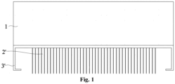
- the handle 3' and a radiator 2' are arranged side by side on the back of the box 1. Since the radiator 2' is attached to the box 1, the width of the box 1 is generally larger than the width of radiator 2' for the sake of appearance.
- the handle 3' increases the size of the box 1 in the width direction, and also increases the volume and the cost of the box 1.
- the external handle 3 is arranged on the external device 2, so that the external handle 3 does not occupy additional space of the box 1, which reduces the occupation of the area of the box 1 after the external handle 3 is mounted, realizes a small box 1, and reduces the cost of the box 1, thereby reducing the cost of the entire electrical apparatus and improving the market competitiveness of the entire electrical apparatus.
- the external handle 3 is detachably fixed to the external device 2. When the external handle 3 is damaged, it is convenient to disassemble the external handle 3 from the external device 2 for maintenance and replace the external handle 3 with a new external handle 3.
- the electrical apparatus further includes a fastener 4, and the fastener 4 is configured to detachably fix the external handle 3 to the external device 2.
- a first mounting hole 31 is provided in the external handle 3, and a second mounting hole 211 is correspondingly provided in the external device 2.
- the fastener 4 is configured to sequentially pass through the first mounting hole 31 and the second mounting hole 211 to fix the external handle 3 to the external device 2, thereby realizing a detachable connection between the external handle 3 and the external device 2.
- the fastener 4 may be a bolt, and the bolt is detachably connected.
- the bolt has advantages of high reliability and low cost.
- the external handle 3 may be detachably connected to the external device 2 through a nut. Specifically, the external device 2 passes through the first mounting hole 31 in the external handle 3. The external handle 3 is detachably connected to the external device 2 by screwing the nut on the external device 2 and abutting the nut against a side of the external handle 3.
- the external handle 3 may be fixed to the external device 2 by bonding or welding, so that the external handle 3 and the external device 2 are connected as an integrated structure, avoiding the external handle 3 from falling off from the external device 2, and enhancing the stability and reliability of the connection between the external handle 3 and the external device 2.
- the external device 2 includes a first device 21 and a second device 22 arranged side by side.
- the number of the external handle 3 is two, and the two external handles 3 are arranged symmetrically on a side face of the first device 21 and a side face of the second device 22.
- multiple external handles 3 may be provided according to actual needs, and the number is not limited to two, and may be three, four, and so on.
- a closed structure is enclosed by the external handle 3 and the external device 2.
- the operator holds the external handle 3 in the closed structure without slipping out of the external handle 3, so that it is stable for holding the external handle 3, and is stable and reliable for carrying the electrical apparatus.
- the external handle 3 is U-shaped, and each of two side walls of the external handle 3 is arranged on the external device 2, so that the structure of the external handle 3 is simple, which is convenient for processing and production, and the closed structure is enclosed by the external handle 3 and the external device 2.
- an anti-skid rubber sleeve is sleeved on the external handle 3, and anti-skid protrusions are provided on an outer surface of the anti-skid rubber sleeve.
- the anti-skid rubber sleeve and the anti-skid protrusions on the outer surface of the anti-skid rubber sleeve have a certain degree of elasticity, which can avoid rigid contact between the operator and the external handle 3, increase the comfort of the operator to hold the external handle 3, and improve the protection for a hand of the operator.
- anti-skid threads may be provided on a circumferential surface of the external handle 3, so as to increase the friction between the operator and the external handle 3, avoid slipping on the external handle 3, thereby ensuring that the operator holds the external handle 3 more stably and reliably.
- the external handle 3 is made of metal, which can prevent deformation of the external handle 3 and ensure the service life of the external handle 3.
Landscapes
- Engineering & Computer Science (AREA)
- Microelectronics & Electronic Packaging (AREA)
- Casings For Electric Apparatus (AREA)
- Surgical Instruments (AREA)
- Beans For Foods Or Fodder (AREA)
- Control And Other Processes For Unpacking Of Materials (AREA)
Abstract
Description
- The present application claims priority to
Chinese Patent Application No. 202121090998.0, titled "ELECTRICAL APPARATUS", filed on May 20, 2021 - The present application relates to the field of electrical technology, and in particular to an electrical apparatus.
- As the power of an electrical apparatus such as an inverter and a combiner box increases, the electrical apparatus requires to be highly miniaturized. In order to facilitate the carrying of the electrical apparatus, a handle is generally arranged on the electrical apparatus. In the conventional technology, the handle is generally arranged externally on the back of a box and occupies a certain space on the back of the box, which increases the volume and the cost of the box.
- As shown in
Figure 1 , in another technical solution of the conventional technology, a handle and a radiator are arranged side by side on the back of the box. Since the radiator is attached to the box, the width of the box is generally greater than the width of the radiator for the sake of appearance. The handle increases the size of the box in the width direction, and also increases the volume and the cost of the box. - The object of present application is to provide an electrical apparatus, and an external handle does not additionally increase the space of the box, so as to reduce the cost of the box and improve the market competitiveness of the electrical apparatus.
- In order to achieve the object, the following technical solutions are adopted in the present application.
- An electrical apparatus includes:
- a box;
- an external device, fixed to an outer side of the box; and
- an external handle, arranged on the external device, where the external handle is configured for carrying of the electrical apparatus.
- By arranging the external handle on the external device, the external handle does not occupy additional space of the box, which reduces the occupation of the area of the box after the external handle is mounted, realizes a small box, and reduces the cost of the box, thereby reducing the cost of the entire electrical apparatus and improving the market competitiveness of the entire electrical apparatus.
- In an embodiment, the external handle is detachably fixed to the external device.
- When the external handle is damaged in the event of a failure, it is convenient to disassemble the external handle from the external device for maintenance and replace the external handle with a new external handle.
- In an embodiment, the electrical apparatus further includes:
a fastener, where a first mounting hole is provided in the external handle, a second mounting hole is correspondingly provided in the external device, and the fastener is configured to sequentially pass through the first mounting hole and the second mounting hole to fix the external handle to the external device. - A detachable connection between the external handle and the external device is realized through the fastener, and is more stable and reliable.
- In an embodiment, the external handle is fixed to the external device by bonding or welding.
- The external handle and the external device are connected into an integrated structure, to prevent the external handle from falling off from the external device and enhance the stability and reliability of the connection between the external handle and the external device.
- In an embodiment, the external device includes a first device and a second device arranged side by side, the number of the external handle is two, and the two external handles are symmetrically arranged on a side face of the first device and a side face of the second device.
- By arranging the two external handles symmetrically on the external device, it is convenient for an operator to carry the electrical apparatus through the two external handles, thereby realizing a more convenient operation.
- In an embodiment, a closed structure is enclosed by the external handle and the external device.
- The operator holds the external handle in the closed structure without slipping out of the external handle, so that it is stable for holding the external handle and is stable and reliable for carrying the electrical apparatus.
- In an embodiment, the external handle is U-shaped, and each of two side walls of the external handle is arranged on the external device.
- The external handle is designed in a U-shape, which makes the structure simple and easy to realize, and ensures the closed structure enclosed by the external handle and the external device.
- In an embodiment, an anti-skid rubber sleeve is sleeved on the external handle, and anti-skid is protrusions are provided on an outer surface of the anti-skid rubber sleeve.
- The friction between the operator and the external handle can be increased by the anti-skid protrusions, avoiding slipping on the external handle and ensuring that the operator holds the external handle more stably and reliably. In addition, the anti-skid rubber sleeve and the anti-skid protrusions on the outer surface of the anti-skid rubber sleeve have a certain degree of elasticity, which can avoid rigid contact between the operator and the external handle, increase the comfort of the operator when holding the external handle, and improve the protection for a hand of the operator.
- In an embodiment, anti-skid threads are provided on a circumferential surface of the external handle.
- The friction between the operator and the external handle is increased, avoiding slipping on the external handle, thereby ensuring that the operator holds the external handle more stably and reliably.
- In an embodiment, the external handle is made of metal.
- The external handle is made of metal, which can prevent deformation of the external handle and ensure the service life of the external handle.
- In an embodiment, the electrical apparatus is an inverter, and the external device is a radiator or a reactor.
- The beneficial effects of the present application are as follows:
- The electrical apparatus is provided according to the present application. The electrical apparatus includes the box, the external device and the external handle. The external device is fixed on the outer side of the box, and the external handle is arranged on the external device. The external handle is configured for carrying of the electrical apparatus. By arranging the external handle on the external device, the external handle does not occupy additional space of the box, which reduces the occupation of the area of the box after the external handle is mounted, realizes a small box and reduces the cost of the box, thereby reducing the cost of the entire electrical apparatus and improving the market competitiveness of the entire electrical apparatus.
-
-
Figure 1 is a schematic structural diagram of an electrical apparatus in the conventional technology; -
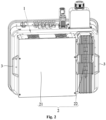
Figure 2 is a schematic structural diagram of an electrical apparatus according to an embodiment of the present application; and -
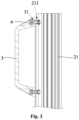
Figure 3 is a section view of a part of an electrical apparatus according to an embodiment of the present application. - Reference numerals in the drawings are as follows:
1 box; 2' radiator; 3' handle; 2 external device; 21 first device; 211 second mounting hole; 22 second device; 3 external handle; 31 first mounting hole; 4 fastener. - In order to clarify the technical problems solved, the technical solutions adopted, and the technical effects achieved by the present application, the technical solutions of the present application are further described below in conjunction with the accompanying drawings and through specific embodiments.
- In the description of the present application, unless otherwise clearly specified and limited, terms "connect to", "connect", and "fix" should be understood in a broad sense, for example, may be a fixed connection, a detachable connection, or a connection to be integrated; may be a mechanical connection or an electric connection; may be a direct connection, or an indirect connection through an intermediary, and may be an internal connection of two components or an interaction relationship between two components. For those skilled in the art, the specific meanings of the terms in the present application can be understood based on specific situations.
- In the present application, unless otherwise clearly specified and limited, a first feature being "on" or "under" a second feature may include the first feature directly contacting the second feature, and may also include the first feature not directly contacting the second feature but contacting through another feature between the first and second features. Moreover, the first feature being "on", "above" and "over" the second feature includes that the first feature is directly above and obliquely above the second feature, or simply indicates that the first feature is higher than the second feature in height with reference to a horizontal line. The first feature being "below", "under" and "beneath" the second feature includes that the first feature is directly below and obliquely below the second feature, or simply indicates that the first feature is lower than the second feature in height with reference to a horizontal line.
- In the description of the embodiments, terms "up", "down", "left", "right" and other orientations or positional relationships are based on the orientations or positional relationships shown in the accompanying drawings, and are only for the convenience of description and simplification of operations, rather than indicating or implying that the device or element must have a specific orientation, be constructed and operated in a specific orientation, and thus should not be understood as a limitation of the present application. In addition, terms "first" and "second" are only used to distinguish in description and have no special meaning.
- As shown in
Figure 2 , an electrical apparatus is provided according to an embodiment of the present application. The electrical apparatus may be an inverter or a combiner box, but is not limited to this, and may also be other electrical apparatuses. - Specifically, as shown in
Figure 2 , the electrical apparatus mainly includes abox 1 and anexternal device 2. Thebox 1 is configured to protect and support internal electrical components, and theexternal device 2 may be a reactor, a radiator, an air duct, or an assembly of a radiator and an air duct. Theexternal device 2 is detachably fixed to thebox 1, and is electrically connected to the electrical components inside thebox 1, thereby achieving the corresponding function of theexternal device 2. - In an embodiment, as shown in
Figure 2 , in order to facilitate the carrying of the electrical apparatus, the electrical apparatus further includes anexternal handle 3. Theexternal handle 3 can be configured for carrying of the electrical apparatus, and provide a force application point for carrying the electrical apparatus for easy operation. - However, in the conventional technology, a handle 3' is generally externally mounted on the back of a
box 1 and occupies a certain space on the back of thebox 1, which increases the volume and the cost of thebox 1. - As shown in
Figure 1 , in another technical solution of the conventional technology, the handle 3' and a radiator 2' are arranged side by side on the back of thebox 1. Since the radiator 2' is attached to thebox 1, the width of thebox 1 is generally larger than the width of radiator 2' for the sake of appearance. The handle 3' increases the size of thebox 1 in the width direction, and also increases the volume and the cost of thebox 1. - In order to solve the above problems, as shown in
Figure 2 , theexternal handle 3 according to the embodiment is arranged on theexternal device 2, so that theexternal handle 3 does not occupy additional space of thebox 1, which reduces the occupation of the area of thebox 1 after theexternal handle 3 is mounted, realizes asmall box 1, and reduces the cost of thebox 1, thereby reducing the cost of the entire electrical apparatus and improving the market competitiveness of the entire electrical apparatus. - In an embodiment, the
external handle 3 is detachably fixed to theexternal device 2. When theexternal handle 3 is damaged, it is convenient to disassemble theexternal handle 3 from theexternal device 2 for maintenance and replace theexternal handle 3 with a newexternal handle 3. - In an embodiment, as shown in
Figure 3 , the electrical apparatus further includes afastener 4, and thefastener 4 is configured to detachably fix theexternal handle 3 to theexternal device 2. Specifically, a first mountinghole 31 is provided in theexternal handle 3, and asecond mounting hole 211 is correspondingly provided in theexternal device 2. Thefastener 4 is configured to sequentially pass through the first mountinghole 31 and thesecond mounting hole 211 to fix theexternal handle 3 to theexternal device 2, thereby realizing a detachable connection between theexternal handle 3 and theexternal device 2. Thefastener 4 may be a bolt, and the bolt is detachably connected. In addition, the bolt has advantages of high reliability and low cost. - It should be noted that in other embodiments, alternatively, the
external handle 3 may be detachably connected to theexternal device 2 through a nut. Specifically, theexternal device 2 passes through the first mountinghole 31 in theexternal handle 3. Theexternal handle 3 is detachably connected to theexternal device 2 by screwing the nut on theexternal device 2 and abutting the nut against a side of theexternal handle 3. - In other embodiments, alternatively, the
external handle 3 may be fixed to theexternal device 2 by bonding or welding, so that theexternal handle 3 and theexternal device 2 are connected as an integrated structure, avoiding theexternal handle 3 from falling off from theexternal device 2, and enhancing the stability and reliability of the connection between theexternal handle 3 and theexternal device 2. - In an embodiment, as shown in
Figure 2 , theexternal device 2 includes afirst device 21 and asecond device 22 arranged side by side. The number of theexternal handle 3 is two, and the twoexternal handles 3 are arranged symmetrically on a side face of thefirst device 21 and a side face of thesecond device 22. By correspondingly arranging the two symmetricalexternal handles 3 on theexternal device 2, it is convenient for the operator to carry the electrical apparatus through the twoexternal handles 3, thereby realizing a more convenient operation. It should be noted that multipleexternal handles 3 may be provided according to actual needs, and the number is not limited to two, and may be three, four, and so on. - In order to facilitate holding the
external handle 3, as shown inFigure 2 , a closed structure is enclosed by theexternal handle 3 and theexternal device 2. The operator holds theexternal handle 3 in the closed structure without slipping out of theexternal handle 3, so that it is stable for holding theexternal handle 3, and is stable and reliable for carrying the electrical apparatus. - In an embodiment, the
external handle 3 is U-shaped, and each of two side walls of theexternal handle 3 is arranged on theexternal device 2, so that the structure of theexternal handle 3 is simple, which is convenient for processing and production, and the closed structure is enclosed by theexternal handle 3 and theexternal device 2. - In an embodiment, an anti-skid rubber sleeve is sleeved on the
external handle 3, and anti-skid protrusions are provided on an outer surface of the anti-skid rubber sleeve. By arranging the anti-skid protrusions, the friction between the operator and theexternal handle 3 can be increased, avoiding slipping on theexternal handle 3, thereby ensuring that the operator holds theexternal handle 3 more stably and reliably. In addition, the anti-skid rubber sleeve and the anti-skid protrusions on the outer surface of the anti-skid rubber sleeve have a certain degree of elasticity, which can avoid rigid contact between the operator and theexternal handle 3, increase the comfort of the operator to hold theexternal handle 3, and improve the protection for a hand of the operator. - It should be noted that in other embodiments, anti-skid threads may be provided on a circumferential surface of the
external handle 3, so as to increase the friction between the operator and theexternal handle 3, avoid slipping on theexternal handle 3, thereby ensuring that the operator holds theexternal handle 3 more stably and reliably. - In addition, in order to ensure the structural strength of the
external handle 3, theexternal handle 3 is made of metal, which can prevent deformation of theexternal handle 3 and ensure the service life of theexternal handle 3. - Apparently, the embodiments of the present application are only examples for clearly illustrating the present application, and are not intended to limit the embodiments of the present application. For those skilled in the art, other variations or changes in different forms may be made based on the above description. It is not necessary and impossible to exhaustively list all the embodiments herein. Any modification, equivalent replacement, and improvement made within the spirit and principles of the present application shall be included within the protection scope of the claims of the present application.
Claims (11)
- An electrical apparatus, comprisinga box (1);an external device (2), fixed to an outer side of the box (1); andan external handle (3), arranged on the external device (2), wherein the external handle (3) is configured for carrying of the electrical apparatus.
- The electrical apparatus according to claim 1, wherein the external handle (3) is detachably fixed to the external device (2).
- The electrical apparatus according to claim 2, further comprising:
a fastener (4), wherein a first mounting hole (31) is provided in the external handle (3), a second mounting hole (211) is correspondingly provided in the external device (2), and the fastener (4) is configured to sequentially pass through the first mounting hole (31) and the second mounting hole (211) to fix the external handle (3) to the external device (2). - The electrical apparatus according to claim 1, wherein the external handle (3) is fixed to the external device (2) by bonding or welding.
- The electrical apparatus according to claim 1, wherein the external device (2) comprises a first device (21) and a second device (22) arranged side by side, the number of the external handle (3) is two, and the two external handles (3) are symmetrically arranged on a side face of the first device (21) and a side face the second device (22).
- The electrical apparatus according to any one of claims 1 to 5, wherein a closed structure is enclosed by the external handle (3) and the external device (2).
- The electrical apparatus according to claim 6, wherein the external handle (3) is U-shaped, and each of two side walls of the external handle (3) is arranged on the external device (2).
- The electrical apparatus according to any one of claims 1 to 5, wherein an anti-skid rubber sleeve is sleeved on the external handle (3), and anti-skid protrusions are provided on an outer surface of the anti-skid rubber sleeve.
- The electrical apparatus according to any one of claims 1 to 5, wherein anti-skid threads are provided on a circumferential surface of the external handle (3).
- The electrical apparatus according to any one of claims 1 to 5, wherein the external handle (3) is made of metal.
- The electrical apparatus according to claim 1, wherein the electrical apparatus is an inverter, and the external device (2) is a radiator or a reactor.
Applications Claiming Priority (2)
| Application Number | Priority Date | Filing Date | Title |
|---|---|---|---|
| CN202121090998.0U CN216217877U (en) | 2021-05-20 | 2021-05-20 | Electrical equipment |
| PCT/CN2021/134977 WO2022242105A1 (en) | 2021-05-20 | 2021-12-02 | Electrical device |
Publications (2)
| Publication Number | Publication Date |
|---|---|
| EP4344366A1 true EP4344366A1 (en) | 2024-03-27 |
| EP4344366A4 EP4344366A4 (en) | 2025-04-23 |
Family
ID=80858477
Family Applications (1)
| Application Number | Title | Priority Date | Filing Date |
|---|---|---|---|
| EP21940548.7A Withdrawn EP4344366A4 (en) | 2021-05-20 | 2021-12-02 | ELECTRICAL DEVICE |
Country Status (5)
| Country | Link |
|---|---|
| US (1) | US20240244776A1 (en) |
| EP (1) | EP4344366A4 (en) |
| CN (1) | CN216217877U (en) |
| AU (1) | AU2021446451A1 (en) |
| WO (1) | WO2022242105A1 (en) |
Family Cites Families (7)
| Publication number | Priority date | Publication date | Assignee | Title |
|---|---|---|---|---|
| JP5538460B2 (en) * | 2011-04-06 | 2014-07-02 | パナソニック株式会社 | Expansion device and information processing system including the same |
| CN202354009U (en) * | 2011-11-22 | 2012-07-25 | 无锡盛莱得新能源科技有限公司 | Heat radiator |
| CN205451970U (en) * | 2015-12-28 | 2016-08-10 | 艾威姆(天津)电气有限公司 | Take reactor of handle |
| CN208095031U (en) * | 2018-04-09 | 2018-11-13 | 周永闯 | A kind of electrical equipment radiator being easily installed |
| KR102066917B1 (en) * | 2018-12-24 | 2020-01-16 | 주식회사 고그린테크 | Carrier-typed portable power supply apparatus |
| CN209766944U (en) * | 2019-04-29 | 2019-12-10 | 江苏佑能实业有限公司 | electrical equipment dehumidification system |
| CN211481825U (en) * | 2020-03-31 | 2020-09-11 | 南昌工程学院 | Electrical equipment heat radiation structure easy to assemble |
-
2021
- 2021-05-20 CN CN202121090998.0U patent/CN216217877U/en active Active
- 2021-12-02 US US18/276,626 patent/US20240244776A1/en active Pending
- 2021-12-02 AU AU2021446451A patent/AU2021446451A1/en not_active Abandoned
- 2021-12-02 EP EP21940548.7A patent/EP4344366A4/en not_active Withdrawn
- 2021-12-02 WO PCT/CN2021/134977 patent/WO2022242105A1/en not_active Ceased
Also Published As
| Publication number | Publication date |
|---|---|
| AU2021446451A1 (en) | 2023-08-31 |
| CN216217877U (en) | 2022-04-05 |
| EP4344366A4 (en) | 2025-04-23 |
| US20240244776A1 (en) | 2024-07-18 |
| WO2022242105A1 (en) | 2022-11-24 |
Similar Documents
| Publication | Publication Date | Title |
|---|---|---|
| EP3664225A1 (en) | High-current connector | |
| EP3770991B1 (en) | Battery pack | |
| US20240244776A1 (en) | Electrical device | |
| CN210290055U (en) | Damping pad, mounting structure and equipment | |
| CN113421812A (en) | Semiconductor process equipment and bearing device thereof | |
| US12615726B2 (en) | Box body, high-voltage box apparatus, energy storage device, and electric equipment | |
| CN208111940U (en) | Low-tension switch cabinet with dust reduction capability | |
| CN212463636U (en) | Wear-proof double-sided circuit board | |
| CN208331611U (en) | A kind of cantilever mechanism of screening machine | |
| CN220359469U (en) | 156W dual-output power supply module | |
| CN210509941U (en) | Ball push rod and electric bed using same | |
| CN214898713U (en) | Battery cabinet connecting and mounting structure | |
| EP4568436A1 (en) | Power conversion device | |
| CN217331616U (en) | Thruster testing device | |
| CN218041884U (en) | A double-beam laminar plasma generator | |
| CN218935881U (en) | Lifting locking mechanism for display bracket and display bracket with lifting locking mechanism | |
| CN212647394U (en) | Fixed convenient high bears display card | |
| CN217359961U (en) | Electric energy quality monitoring device | |
| CN220051539U (en) | Fixing device for processing surface of middle frame of mobile phone | |
| CN218181429U (en) | Quick-release support for computer mainboard | |
| CN216390780U (en) | Switching power supply with stable operation and long service life | |
| CN215445849U (en) | Adjustable base for computer | |
| CN212031569U (en) | Limiting structure of circuit board in electric meter box | |
| CN216764229U (en) | Front protective cover for unmanned forklift | |
| CN219536553U (en) | Communication multi-protocol converter with shielding structure |
Legal Events
| Date | Code | Title | Description |
|---|---|---|---|
| STAA | Information on the status of an ep patent application or granted ep patent |
Free format text: STATUS: THE INTERNATIONAL PUBLICATION HAS BEEN MADE |
|
| PUAI | Public reference made under article 153(3) epc to a published international application that has entered the european phase |
Free format text: ORIGINAL CODE: 0009012 |
|
| STAA | Information on the status of an ep patent application or granted ep patent |
Free format text: STATUS: REQUEST FOR EXAMINATION WAS MADE |
|
| 17P | Request for examination filed |
Effective date: 20230808 |
|
| AK | Designated contracting states |
Kind code of ref document: A1 Designated state(s): AL AT BE BG CH CY CZ DE DK EE ES FI FR GB GR HR HU IE IS IT LI LT LU LV MC MK MT NL NO PL PT RO RS SE SI SK SM TR |
|
| DAV | Request for validation of the european patent (deleted) | ||
| DAX | Request for extension of the european patent (deleted) | ||
| A4 | Supplementary search report drawn up and despatched |
Effective date: 20250321 |
|
| RIC1 | Information provided on ipc code assigned before grant |
Ipc: H05K 5/02 20060101AFI20250317BHEP |
|
| STAA | Information on the status of an ep patent application or granted ep patent |
Free format text: STATUS: THE APPLICATION IS DEEMED TO BE WITHDRAWN |
|
| 18D | Application deemed to be withdrawn |
Effective date: 20251009 |