EP4344349A1 - Vapour generating device - Google Patents
Vapour generating device Download PDFInfo
- Publication number
- EP4344349A1 EP4344349A1 EP22196807.6A EP22196807A EP4344349A1 EP 4344349 A1 EP4344349 A1 EP 4344349A1 EP 22196807 A EP22196807 A EP 22196807A EP 4344349 A1 EP4344349 A1 EP 4344349A1
- Authority
- EP
- European Patent Office
- Prior art keywords
- induction
- vapour generating
- receiving coil
- generating device
- current
- Prior art date
- Legal status (The legal status is an assumption and is not a legal conclusion. Google has not performed a legal analysis and makes no representation as to the accuracy of the status listed.)
- Pending
Links
- 230000006698 induction Effects 0.000 claims abstract description 258
- 238000010438 heat treatment Methods 0.000 claims abstract description 223
- 239000000126 substance Substances 0.000 claims abstract description 69
- 230000003993 interaction Effects 0.000 claims abstract description 39
- 239000000463 material Substances 0.000 claims description 29
- 238000012545 processing Methods 0.000 claims description 9
- 230000003647 oxidation Effects 0.000 claims description 8
- 238000007254 oxidation reaction Methods 0.000 claims description 8
- 229910045601 alloy Inorganic materials 0.000 claims description 7
- 239000000956 alloy Substances 0.000 claims description 7
- 230000005415 magnetization Effects 0.000 claims description 7
- 238000000034 method Methods 0.000 claims description 6
- 230000008569 process Effects 0.000 claims description 6
- 238000004519 manufacturing process Methods 0.000 description 15
- 241000208125 Nicotiana Species 0.000 description 12
- 235000002637 Nicotiana tabacum Nutrition 0.000 description 12
- 230000005672 electromagnetic field Effects 0.000 description 11
- 230000001276 controlling effect Effects 0.000 description 10
- 238000004891 communication Methods 0.000 description 9
- 239000003990 capacitor Substances 0.000 description 7
- 238000010586 diagram Methods 0.000 description 7
- 239000000796 flavoring agent Substances 0.000 description 6
- 235000019634 flavors Nutrition 0.000 description 6
- 239000000203 mixture Substances 0.000 description 6
- 238000004804 winding Methods 0.000 description 6
- 238000001514 detection method Methods 0.000 description 5
- 238000003780 insertion Methods 0.000 description 5
- 230000037431 insertion Effects 0.000 description 5
- 239000002184 metal Substances 0.000 description 5
- 238000013459 approach Methods 0.000 description 4
- 230000008859 change Effects 0.000 description 4
- 239000007788 liquid Substances 0.000 description 4
- 238000012360 testing method Methods 0.000 description 4
- PEDCQBHIVMGVHV-UHFFFAOYSA-N Glycerine Chemical compound OCC(O)CO PEDCQBHIVMGVHV-UHFFFAOYSA-N 0.000 description 3
- DNIAPMSPPWPWGF-UHFFFAOYSA-N Propylene glycol Chemical compound CC(O)CO DNIAPMSPPWPWGF-UHFFFAOYSA-N 0.000 description 3
- 230000003247 decreasing effect Effects 0.000 description 3
- 230000007547 defect Effects 0.000 description 3
- 239000003571 electronic cigarette Substances 0.000 description 3
- 230000006870 function Effects 0.000 description 3
- 229910001092 metal group alloy Inorganic materials 0.000 description 3
- 239000002245 particle Substances 0.000 description 3
- 230000010363 phase shift Effects 0.000 description 3
- 238000004458 analytical method Methods 0.000 description 2
- 230000001419 dependent effect Effects 0.000 description 2
- 230000002349 favourable effect Effects 0.000 description 2
- 239000000446 fuel Substances 0.000 description 2
- 239000006193 liquid solution Substances 0.000 description 2
- 239000007787 solid Substances 0.000 description 2
- SNICXCGAKADSCV-JTQLQIEISA-N (-)-Nicotine Chemical compound CN1CCC[C@H]1C1=CC=CN=C1 SNICXCGAKADSCV-JTQLQIEISA-N 0.000 description 1
- 101100091482 Caenorhabditis elegans rop-1 gene Proteins 0.000 description 1
- HBBGRARXTFLTSG-UHFFFAOYSA-N Lithium ion Chemical compound [Li+] HBBGRARXTFLTSG-UHFFFAOYSA-N 0.000 description 1
- 238000010521 absorption reaction Methods 0.000 description 1
- 239000000443 aerosol Substances 0.000 description 1
- 230000008901 benefit Effects 0.000 description 1
- 238000006243 chemical reaction Methods 0.000 description 1
- 238000002485 combustion reaction Methods 0.000 description 1
- 238000004590 computer program Methods 0.000 description 1
- 238000010276 construction Methods 0.000 description 1
- 230000007423 decrease Effects 0.000 description 1
- 230000000694 effects Effects 0.000 description 1
- 239000008187 granular material Substances 0.000 description 1
- 230000001788 irregular Effects 0.000 description 1
- 229910001416 lithium ion Inorganic materials 0.000 description 1
- 229960002715 nicotine Drugs 0.000 description 1
- SNICXCGAKADSCV-UHFFFAOYSA-N nicotine Natural products CN1CCCC1C1=CC=CN=C1 SNICXCGAKADSCV-UHFFFAOYSA-N 0.000 description 1
- 230000000737 periodic effect Effects 0.000 description 1
- 229920000642 polymer Polymers 0.000 description 1
- 230000001737 promoting effect Effects 0.000 description 1
- 230000001105 regulatory effect Effects 0.000 description 1
- 230000000391 smoking effect Effects 0.000 description 1
- 239000002887 superconductor Substances 0.000 description 1
- 235000019505 tobacco product Nutrition 0.000 description 1
Images


Classifications
-
- H—ELECTRICITY
- H05—ELECTRIC TECHNIQUES NOT OTHERWISE PROVIDED FOR
- H05B—ELECTRIC HEATING; ELECTRIC LIGHT SOURCES NOT OTHERWISE PROVIDED FOR; CIRCUIT ARRANGEMENTS FOR ELECTRIC LIGHT SOURCES, IN GENERAL
- H05B6/00—Heating by electric, magnetic or electromagnetic fields
- H05B6/02—Induction heating
- H05B6/10—Induction heating apparatus, other than furnaces, for specific applications
- H05B6/105—Induction heating apparatus, other than furnaces, for specific applications using a susceptor
- H05B6/108—Induction heating apparatus, other than furnaces, for specific applications using a susceptor for heating a fluid
-
- A—HUMAN NECESSITIES
- A24—TOBACCO; CIGARS; CIGARETTES; SIMULATED SMOKING DEVICES; SMOKERS' REQUISITES
- A24F—SMOKERS' REQUISITES; MATCH BOXES; SIMULATED SMOKING DEVICES
- A24F40/00—Electrically operated smoking devices; Component parts thereof; Manufacture thereof; Maintenance or testing thereof; Charging means specially adapted therefor
- A24F40/40—Constructional details, e.g. connection of cartridges and battery parts
- A24F40/46—Shape or structure of electric heating means
- A24F40/465—Shape or structure of electric heating means specially adapted for induction heating
-
- A—HUMAN NECESSITIES
- A24—TOBACCO; CIGARS; CIGARETTES; SIMULATED SMOKING DEVICES; SMOKERS' REQUISITES
- A24F—SMOKERS' REQUISITES; MATCH BOXES; SIMULATED SMOKING DEVICES
- A24F40/00—Electrically operated smoking devices; Component parts thereof; Manufacture thereof; Maintenance or testing thereof; Charging means specially adapted therefor
- A24F40/50—Control or monitoring
-
- H—ELECTRICITY
- H05—ELECTRIC TECHNIQUES NOT OTHERWISE PROVIDED FOR
- H05B—ELECTRIC HEATING; ELECTRIC LIGHT SOURCES NOT OTHERWISE PROVIDED FOR; CIRCUIT ARRANGEMENTS FOR ELECTRIC LIGHT SOURCES, IN GENERAL
- H05B6/00—Heating by electric, magnetic or electromagnetic fields
- H05B6/02—Induction heating
- H05B6/06—Control, e.g. of temperature, of power
-
- A—HUMAN NECESSITIES
- A24—TOBACCO; CIGARS; CIGARETTES; SIMULATED SMOKING DEVICES; SMOKERS' REQUISITES
- A24F—SMOKERS' REQUISITES; MATCH BOXES; SIMULATED SMOKING DEVICES
- A24F40/00—Electrically operated smoking devices; Component parts thereof; Manufacture thereof; Maintenance or testing thereof; Charging means specially adapted therefor
- A24F40/20—Devices using solid inhalable precursors
Definitions
- the present invention relates to a vapour generating device and in particular relates to tuning of settings of a vapour generating device for inductively heating a vapour generating substance.
- vapour generating devices are commonly handheld device.
- such handheld vapour generating device may be said to belong to two groups: electronic cigarettes and tobacco vapour devices.
- Electronic cigarettes also called e-cigarettes, vaporizers or cig-a-likes are vapour generating device that simulate tobacco smoking and do not contain tobacco.
- These devices generate inhalable vapour by heating a liquid solution containing flavour releasing substance.
- flavour releasing substance is nicotine.
- the liquid solution is also called e-liquid.
- the tobacco vapour devices also known as heated tobacco products, on the other hand contain tobacco that is heated but not burned to create an inhalable vapour.
- vapour generating substance such e-liquid used in electronic cigarettes or tobacco used in tobacco vapour products may be called a vapour generating substance.
- the vapour generating substance is placed in a container, that may also be called cartridge or tobacco stick, that can be inserted in and removed from the vapour generating device by the user. Therefore, the container in which the vapour generating substance is placed is a consumable article and is also called a consumable.
- vapour generating device may apply different approaches.
- One simple approach is based on electrical heating also known as resistive heating and involves providing an electrical power to a heating element which is in direct or indirect contact with the vapour generating substance.
- electrical heating also known as resistive heating and involves providing an electrical power to a heating element which is in direct or indirect contact with the vapour generating substance.
- electrical power is provided to the heating element.
- the heating element is heated, which in turn heats the vapour generating substance to generate vapour that can be inhaled by the user.
- an induction heating coil is provided in the vapour generating device and in addition at least one induction heatable element is provided in the vapour generating device or more commonly in the consumable article.
- the induction heatable element is also called a susceptor.
- the susceptor may be in direct or an indirect contact with the vapour generating substance or may be arranged in the vicinity of the vapour generating substance.
- an electromagnetic field is generated.
- the susceptor being placed in the electromagnetic field absorbs the electromagnetic energy and converts it to heat. With the generated heat the vapour generating substance is heated and vapour is generated that can be inhaled by the user.
- the susceptor is placed in the consumable article and arranged such that it is surrounded by the vapour generating substance.
- the susceptor is arranged such that it is buried completely or at least partly in the vapour generating substance.
- This way of providing the susceptor requires highly precise control of the position of the susceptor within the consumable article in order that the susceptor absorbs optimally the generated electromagnetic field to thereby optimally heat the vapour generating substance to produce vapour.
- small differences may exist between the different susceptors due to, for example, manufacturing tolerances of the different susceptors.
- such small differences may exist with respect to the shape or the material such as metal alloy composition of the susceptor or the position of the susceptor in the consumable article.
- the prescribed specifications may include specifications as to the position, size, shape, thickness, material composition and similar of the susceptor. For this, normally, the susceptor position, size, material, thickness and/or shape are measured. As a result, some of the susceptors and consequently some of the consumable articles may be rejected which decreases the production yield of consumable articles and impacts the product costs as well as results in higher manufacturing costs and higher manufacturing testing costs.
- the time between production of the susceptor and its actual use has also influence on the properties of the susceptor since this storage time as well as the storage conditions influences the rusting or the oxidation degree of the susceptor.
- a vapour generating device comprising: a heating compartment extending along a first direction; an induction heating coil arranged around the heating compartment and extending along the first direction and being arranged to inductively heat at least one induction heatable element being positioned in the heating compartment to thereby heat a vapour generating substance to produce a vapour; a power supply; a converting circuit configured to convert a direct current supplied from the power supply into an alternating current or a pulsating current and apply the alternating current or pulsating current to the induction heating coil; and a control unit configured to:
- the present invention proposes automatically detecting the variability of the susceptor arranged in the consumable article, said consumable article comprising a vapour generating substance to be heated by the susceptor to produce vapour.
- variability is to be understood as a variance in parameters of the susceptor from parameters being defined as standard parameters.
- the standard parameters may be defined by the manufacturer of the vapour generating device and/or of the consumable article.
- the parameters may include one or more of a shape of the susceptor, size of the susceptor such as its length and/or thickness, position of the susceptor within the consumable article, material composition of the susceptor such as for example material alloy variation of the susceptor, degree of oxidation and/or similar.
- the present invention proposes further allowing the vapour generating device to tune its settings thereby optimizing them for the specific inserted susceptor. This results in higher production yield of consumable articles since the vapour generating device can accept larger tolerances between susceptors of different consumable articles, and further results in reduced manufacturing costs and reduced manufacturing tests costs as well as increased device efficiency and increased sensorial experience for the user since the settings of the vapour generating device are optimized for the specific inserted susceptor.
- Figure 1A shows a schematic view of a vapour generating device 1 according to an embodiment of the present invention.
- the vapour generating device 1 may be a handheld device.
- the vapour generating device 1 may have, as shown in figure 1A a pebble-like shape.
- the shape of the vapour generating device 1 is not limited to a pebble-like shape and other shapes are also possible, for example a cylindrical shape.
- the vapour generating device 1, as it is shown in figure 1A comprises a housing 2.
- the vapour generating device 1, as shown in figure 1A may further comprise an access portion.
- the access portion is arranged normally but not limited to in the top end part of the vapour generating device 1 and may comprise access means 13 for opening and closing an opening to a heating compartment of the vapour generating device 1.
- a user may place at least one consumable article 100 (example being shown in figure 1B ) comprising vapour generating substance.
- the vapour generating substance is heated by a power supplied by a power supply.
- the housing 2 of the vapour generating device 1 may have a smooth outer surface which together with the pebble-like shape provides a physical ergonomic advantage for the user.
- the housing 2 houses at least the mentioned heating chamber and houses further components of the vapour generating device 1 as elaborated below.
- the material of the housing 2 may be a metal or a polymer-based material or a composition of both.
- the user can place a consumable article 100 (example being shown in figure 1B ) containing a vapour generating substance into the heating chamber by, for example, operating the access means 13 for opening and closing the opening to the heating compartment of the vapour generating device 1.
- the access means 13 may comprise in one embodiment of the present invention, for example, a lid that can at least be partly removed from the housing 2 to thereby expose the opening of the heating compartment.
- the access means 13 may comprise, for example, a slider. The slider 13 may be moved between two positions such as opened position and closed position for exposing and covering the opening of the heating compartment.
- the access means may comprise, for example, a trap door.
- the vapour generating device 1 may comprise on the outer side of the housing 2 indication/operation means 3.
- the indication/operation means 3 may comprise input means (comprising for example one or more buttons or one or more touch buttons on a display) for controlling, for example turning on or off the vapour generating device 1.
- the indication/operation means 3 may in addition or alternatively comprise other means, for example one or more light emitting devices and/or a display for indicating different information to the user such as the current status of the power supply, for example the remaining amount of charge in the power supply and/or the amount of consumption of the vapour generating substance in the consumable article 100 and similar.
- FIG 1B shows a schematic view of the consumable article 100 to be inserted in the vapour generating device 1 according to the embodiment of the present invention.
- the consumable article 100 may be a stick comprising tobacco and/or tobacco material and/or other suitable substance that is heated but not burned in the heating compartment to create an inhalable vapour.
- vapour may be used interchangeably with the term "aerosol”.
- the consumable article 100 may have an elongated form, for example a cylindrical form as shown in figure 1B .
- the consumable article 100 may be partitioned in two parts: the first part 110 may be a filter portion or may comprise a filter portion, while in the second part 150 the vapour generating substance is arranged as will be elaborated in more details further below.
- the second part 150 also at least one induction heatable element also called susceptor is arranged.
- Figure 1C shows a schematic view of the vapour generating device 1 according to the embodiment of the present invention with an inserted consumable article 100.
- the first part of the consumable article 100 is entirely or at least partly extending outside of the vapour generating device 1 so that the user can thereby inhale the generated vapour by placing this part at least partly in the mouth.
- the access means 13 are moved to expose the opening of the heating compartment so that the user can insert the consumable article 100 in the heating compartment.
- the consumable article 100 to be used with the vapour generating device 1 of the present invention does not need to comprise the first part 110 which is a filter portion or may comprise a filter portion.
- the consumable article 100 may only comprise the second part 150 in which the vapour generating substance is arranged.
- the vapour generating device 1 may comprise a mouthpiece or other suitable part through which the user can inhale the generated vapour.
- a mouthpiece or other part is not obligatory.
- the vapour generating device 1 may still comprise a mouthpiece.
- Figure 2A shows a schematic view of the functional components of the vapour generating device 1 of the embodiment of the present invention.
- Figure 2B shows a schematic view of the functional components of the vapour generating device 1 of the embodiment of the present invention with the consumable article 100 being inserted in the vapour generating device 1.
- the heating compartment 11 mentioned above may be such that the user can place one consumable article 100 at a time or the user may place more than one consumable article 100 at a time. In the following, it will be assumed that the heating compartment 11 is such that the user can place one consumable article 100 at a time in the heating compartment 11.
- the heating compartment 11 may also have a cylindrical form as well as the consumable article 100.
- the form of the consumable article 100 and the form of the heating chamber 11 are not to be seen as limiting to the present invention.
- the heating compartment 11 extends along a first direction, which in figure 2A is the up-down direction.
- the user places the consumable article 100 in the heating compartment 11 by operating the access means 13 to expose the opening of the heating compartment 11.
- Figure 1B shows a schematic view of the vapour generating device 1 with the inserted consumable 100.
- the user places the access means 13 in the opened position and inserts the consumable 100 in the heating compartment 11 via the thereby exposed opening.
- the access means 13 is a slider
- the user slides the slider to the side as shown in figure 1C and figure 2B (along the left-right direction in figure 2A ) so that it is in the opened position ( figure 2B ).
- the heating compartment 11 has the above-mentioned opening at one end (up direction in figure 2A ) and further comprises a base portion at the opposite end (down direction in figure 2A ).
- the heating compartment 11 is therefore arranged to receive, in use, via the opening, the consumable article 100 to be heated by induction heating as elaborated later.
- “In use” is to be understood in the sense that the user may at least insert the consumable article 100 in the heating compartment 11 via the opening by operating the access means 13. In use, the user may in addition operate the vapour generating device 1 to heat the vapour generating substance arranged in the consumable article 100.
- the vapour generating substance and the at least one induction heatable element are arranged in the heating compartment 11.
- An example of the arrangement for an exemplary at least one induction heatable element 130 is shown in figure 2B .
- the user may know that the consumable article 100 is completely inserted in the heating compartment 11 by, for example, perceiving that the consumable article 100 abates against the base portion of the heating compartment 11.
- a member may be provided on the consumable article 100 that ensures that the consumable article 100 is inserted in the heating compartment 11 such that the vapour generating substance 120 and the at least one induction heatable element 130 are arranged in the heating compartment 11.
- the heating compartment 11 may be in gaseous connection with an air inlet and an air outlet (not shown in the figures) formed in the housing 2. This allows air to be drawn by the user through the air outlet (inlet).
- the vapour generating device 1 according to different embodiments of the present invention with the consumable article 100 inserted in the heating compartment 11 may also be called a vapour generating system.
- a vapour generating system according to the present invention comprises the vapour generating device 1 according to different embodiments of the present invention and the consumable article 100 described in the different embodiments of the present invention.
- such system for an exemplary configuration of the at least one induction heatable element 130 and the vapour generating substance 120 is shown schematically in figure 2B .
- the vapour generating device 1 comprises further an induction heating coil 12.
- the induction heating coil 12 is arranged to extend along the first direction. Accordingly, the induction heating coil 12 is arranged to extend along the heating compartment 11.
- the induction heating coil 12 may be seen as being wrapped around the heating compartment 11.
- the induction heating coil 12 being wrapped around the heating compartment 11 may also have a cylindrical form.
- the heating compartment 11 is defined thus radially inward of the induction heating coil 12 and has a wall around a radially inner side of the induction heating coil 12 around which wall the induction heating coil 12 is wrapped.
- the induction heating coil 12 may have such a length such that the vapour generating substance 120 or at least the at least one induction heatable element 130 is completely or partly within the part of the heating compartment 11 along which the induction heating coil 12 extends when the consumable article 100 is completely inserted in the heating compartment 11.
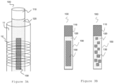
- FIG 3A shows in more details in figure 3A .
- the induction heating coil 12 is arranged around the heating compartment 11 and extends along the heating compartment 11 such that the at least one heatable element 130 which in the embodiment shown in figure 3A has an elongated shape is at least partly within the part of the heating compartment 11 along which the induction heating coil 12 extends.
- more than one induction heating coil 12 may be arranged along the heating compartment 11 to thereby heat different portions of the vapour generating substance 120.
- the induction heating coil 12 is arranged to inductively heat the at least one induction heatable element 130 being positioned in the heating compartment 11 to thereby heat the vapour generating substance 120 to produce a vapour.
- an electromagnetic field EM
- the at least one induction heatable element 130 being positioned in the heating compartment 11 absorbs the electromagnetic energy and converts it to heat. With the generated heat the vapour generating substance is heated and vapour is generated that can be inhaled by the user. Since the magnetic field component of the electromagnetic field is predominantly responsible for the interaction with the susceptor, in the following description the terms electromagnetic field and magnetic field are used interchangeably with each other. The user may inhale the produced vapour.
- the user may inhale the produced vapour through the first portion 110 of the consumable article 100.
- the vapour generating device 1 comprises a mouthpiece or similar the user may inhale the produced vapour via the mouthpiece or similar.
- FIG. 3B shows details of the possible structure of the consumable article 100 according to embodiments of the present invention.
- a consumable article 100 in which the first part 110 is a filter portion or comprises a filter portion, however this is not mandatory.
- the vapour generating substance 120 and the at least one induction heatable element 130 are arranged in the second part 150 of the consumable article 100 .
- the at least one induction heatable element 130 is buried into the vapour generating substance 120.
- the consumable article 100 comprises one induction heatable element 130 having a rectangular shape (plate-like shape) and being buried into the vapour generating substance 120.
- the induction heatable element 130 being buried into the vapour generating substance 120 is to be understood as the induction heatable element 130 being at least partly covered by the vapour generating substance 120.
- the at least one induction heatable element 130 is a rectangular thin plate (plate-shaped) buried inside the vapour generating substance 120 which may be shaped into a cylindrical form.
- the consumable article 100 comprises one plate-shaped induction heatable element, however this is not limiting and more than one plate-shaped induction heatable elements 130 arranged parallel to each other may be provided.
- the thickness of the induction heatable element 130 may be in the range of a micrometre to one or more millimetres. Additionally, or alternatively, other shape (e.g., cylindrical shape) induction heatable element can be employed.
- the vapour generating substance 120 is a flavour-release medium which may be any material or combination of materials which can be heated to release a vapour for inhalation by the user.
- the flavour-release medium may be tobacco or a tobacco material and may be impregnated with a vapour-forming medium such as propylene glycol or glycerol.
- a vapour-forming medium such as propylene glycol or glycerol.
- the vapour generating substance 120 may comprise any flavour-release substance in solid or liquid form which may be heated to produce a vapour.
- the vapour generating substance may comprise more than one flavour-release medium.
- the vapour generating substance 120 may comprise a granulated material which is shaped into a suitable shape. Suitable may be understood in the sense of a shape that is suitable for the specific consumable article 100 in terms of, for example, its form.
- the vapour generating substance 120 may be shaped in a cylindrical shape in this embodiment of the present invention.
- the shape of the vapour generating substance 120 is not limited to a cylindrical shape. In other words, the vapour generating substance 120 may be shaped in a different shape when solid or may be placed within a container with a suitable shape when liquid.
- the consumable article 100 may comprise more than one induction heatable elements 130 with a different shape than a rectangular thin plate.
- the consumable article 100 may comprise plurality of induction heatable elements 130 each in the form of a particle as shown in the right-hand side of figure 3B .
- the particles may have different shape, such as spheres, platelets, rectangles or similar.
- the particles may be distributed throughout the vapour generating substance 120 in a regular pattern or irregular pattern.
- combination of the left-hand side and the right-hand side of figure 3B can be also employed.
- the at least one induction heatable element 130 and the vapour generating substance 120 may be in a direct or indirect contact.
- the indirect contact may mean that a further material is present between the at least one induction heatable element 130 and the vapour generating substance 120.
- a material also called intermediate material
- the direct contact may mean that the vapour generating substance 120 adheres to the surface of the at least one induction heatable element 130 without an intermediate material.
- the material of the at least one induction heatable element 130 is a material, such as metal, that can interact with an electromagnetic field.
- the vapour generating substance 120 is heated by induction heating. More specifically, a changing (varying) current, such as an alternating current is applied to the induction heating coil 12 and a changing magnetic field is generated. Since the at least one induction heatable element 130 is completely or partly within the part of the heating compartment 11 along which the induction heating coil 12 extends, the at least one induction heatable element 130 is completely or at least partly within the generated changing magnetic field.
- the changing magnetic field generates Eddy currents in the at least one induction heatable element 130.
- the at least one induction heatable element 130 has electrical resistance to the generated Eddy currents and hence the flow of the Eddy currents generates Joule heat within the at least one induction heatable element 130.
- the heated at least one induction heatable element 130 heats thereby the vapour generating substance 120 to produce vapor.
- the material of the induction heatable element 130 is chosen such that it is heated at least up to a temperature at which the generated heat in the at least one induction heatable element 130 can heat the vapour generating substance to a temperature at which vapour generation occurs. If the metal of the at least one induction heatable element 130 is magnetic than a heating due to hysteresis effect in such magnetic susceptor is also possible.
- the material of the at least one induction heatable element 130 is a high temperature superconductor.
- the at least one induction heatable element 130 is buried in the vapour generating substance 120.
- the at least one induction heatable element 130 is arranged around the vapour generating substance 120 with or without an intermediate material or is arranged at a distance from the vapour generating substance 120.
- the vapour generating device 1 comprises further a power supply 50.
- the power supply 50 may comprise a battery for example a rechargeable battery (BAT) (e.g., lithium-ion secondary battery) or any other kind of power source (e.g., capacitor or fuel cell) suitable to supply electric current to the induction heating coil 12.
- BAT rechargeable battery
- the power supply normally supplies a direct current.
- the power supply 50 is electrically connected to the induction heating coil 12 via a converting circuit 20.
- the converting circuit 20 is configured to convert the direct current supplied from the power supply 50 into an alternating current or a pulsating current and apply the alternating current or pulsating current to the induction heating coil 12.
- the alternating current and the pulsating current may be commonly referred to as a changing current or a varying current in the present description. Details of the converting circuit 20 in an embodiment of the present invention will be elaborated later with respect to figure 7 , figure 8 and figure 9 .
- a pulsating current is a periodic current which changes in value but in difference to alternating current does not change in direction.
- the pulsating current therefore comprises a plurality of pulses.
- the pulses may be continuous but there may also exist a period between the pulses in which the value of the current is approximately 0.
- the term "approximately” is used to account for small variations of the current around the value of 0 caused by tolerances of the electronic elements in the converting circuit 20 for example.
- the pulses may be sinusoidal (and hence be expressed by sinusoidal function), however, this is not limiting to the present invention and other function describing the pulses is also possible.
- the pulses may also be rectangular.
- the vapour generating device 1 comprises further a control unit 30.
- the control unit 30 is any suitable unit or comprises any suitable unit such as computer processing unit that can perform computer processing.
- the control unit 30 (also called controller) may be for example a microcontroller unit (MCU) and/or micro processing unit (MPU).
- the control unit 30 may comprise storage means, such as a memory, not shown in the figure.
- the memory may also be a separate unit from the control unit also placed inside the housing 2. The memory may store different information needed for the processing by the control unit 30, as will be elaborated further below.
- the memory may store computer program (code) comprising instructions which, when the program is executed by the control unit 30, cause the control unit 30 to carry out the processing of the embodiment of the present invention as will be elaborated further below.
- the control unit 30 may comprises a communication interface.
- the communication interface may support Bluetooth Low Energy (BLE).
- the control unit 30 is configured to control the converting circuit 20 to convert a direct current supplied from the power supply into an alternating current or a pulsating current and apply the alternating current or pulsating current to the induction heating coil 12.
- the control unit 30 may be configured to control the elements of the converting circuit 20 described further below with reference to figures 7 , 8 and 9 by controlling the switch frequency, the on/off time and similar of the corresponding components.
- the alternating current or a pulsating current may be an alternating current or a pulsating current to be applied to the induction heating coil 12 for inductively heating the at least one induction heatable element 130 to thereby heat the vapour generating substance 120 to produce a vapour for generation. Further, the alternating current or pulsating current may be applied to the induction heating coil 12 to be used for identifying at least one parameter of the at least one induction heatable element 130 positioned in the heating compartment 11 based on an interaction between the alternating current or the pulsating current and the at least one induction heatable element 130.
- first alternating current and the term “first pulsating current” is used to denote the alternating current and pulsating current applied to the induction heating coil 12 and used for identifying at least one parameter of the at least one induction heatable element 130 positioned in the heating compartment 11.
- This current may correspond to the current applied to the induction heating coil 12 to inductively heat the at least one induction heatable element 130 being positioned in the heating compartment to thereby heat the vapour generating substance 120 to produce a vapour but does not necessarily need to.
- control unit 30 is configured to control the converting circuit 20 to apply the first alternating current or the first pulsating current to the induction heating coil 12. It is to be understood that the magnitude of the first alternating current or first pulsating current may also cause heating of the at least one induction heatable element 130. However, the magnitude of the first alternating current or first pulsating current if needed may be chosen such that even if heated the at least one induction heatable element 130 is heated below a temperature at which it may be expected that a vapour is produced from the vapour generating substance 120.
- control unit 30 is configured to control the converting circuit 20 to apply the first alternating current or the first pulsating current to the induction heating coil 12.
- the control unit 20 is further configured to identify at least one parameter of the at least one induction heatable element 130 positioned in the heating compartment 11 based on an interaction between the first alternating current or the first pulsating current and the at least one induction heatable element 130.
- the control unit 30 is further configured to select at least one setting for controlling the heating of the at least one induction heatable element 130 by the induction heating coil 12 based on the identified at least one parameter of the at least one induction heatable element.
- the vapour generating device 1 comprises further detecting means 40 (not showed in figures 2A and 2B ) for detecting a characteristic of the interaction.
- the control unit 30 is configured to identify the at least one parameter of the at least one induction heatable element 130 based on said detected characteristic.
- the identified at least one parameter of the at least one induction heatable element 130 may be at least one of length, position within the consumable article 100, variance from a standard shape, material alloy variation and degree of oxidation.
- the characteristic of the interaction may be any signal that represents or is related to the interaction between the alternating current or pulsating current and the at least one induction heatable element 130 and enables the control unit 30 to identify said parameter of the at least one induction heatable element 130.
- the characteristic may be any one of or being related to or representing any one of phase shift between transmitted and returned frequencies, magnitude of applied alternating or pulsating current in comparison to magnitude of induced or magnetization current sensed with different means, time duration of reflected signal, time difference between the expected reflected signal and the actual reflected signal and similar as elaborated further below.
- Eddy currents are generated in the at least one induction heatable element 130.
- the generated Eddy currents in the at least one induction heatable element 130 in turn induce their own magnetic field (may also be called here below Eddy field).
- This interaction between the at least one induction heatable element 130 and the changing current reflects at least one parameter of the at least one induction heatable element 130 such as the length, position within the consumable article 100 (and hence position in the heating compartment 11), variance from a standard shape, material alloy variation and degree of oxidation of the specific induction heatable element 130. For sensing the interaction different working principles may be used.
- Figure 4A shows an embodiment of the present invention according to which a first varying current, for example a first pulsating current (I 0 ), is applied to the induction heating coil 12.
- the first pulsating current comprises one or more pulses with a predetermined duration.
- the pulses may also be called transmitted pulses.
- the first pulsating current (I 0 ) may comprise a period between two consecutive pulses during which the current is 0 or approximately 0.
- Each short pulse of the first pulsating current (I 0 ) applied to the induction heating coil 12 creates a magnetic field (dashed line in the left-hand side in figure 4A ). The magnetic field rapidly collapses when the pulse is turned off.
- the collapse of the magnetic field creates a current in the induction heating coil 12 (I 1 ) as a reflected pulse (solid line in the right-hand side in figure 4A ).
- the transmitted pulse creates Eddy currents in the at least one heatable induction element 130 which generates as a consequence its own electromagnetic field (Eddy field).
- Eddy field When the transmitted pulse's magnetic field collapses resulting in the reflected pulse, the opposing magnetic field generated by the Eddy currents in the at least one induction heatable element 130 makes the reflected pulse take longer to disappear.
- the time difference in duration of the reflected pulse (time difference between the expected reflected pulse and the actual reflected pulse) reflects the induced Eddy currents in the at least one induction heatable element 130 and hence the interaction between the at least one induction heatable element 130 and the first pulsating current.
- This interaction reflects (is related to or dependent on) at least one parameter of the at least one induction heatable element 130 such as the length, position within the consumable article, variance from a standard shape, material alloy variation and degree of oxidation.
- Figure 4B shows a further embodiment of the present invention according to which a first varying current, for example a first alternating current (I 0 ) is applied to the induction heating coil 12 which generates an electromagnetic field (dashed line in figure 4B ).
- the first alternating current generates Eddy currents in the at least one induction heatable element 130.
- the generated Eddy currents in the at least one induction heatable element 130 in turn induce their own magnetic field (solid line in figure 4B ).
- one or more receiving coils 121 are used. More specifically, this generated magnetic field induces a current in the one or more receiving coils 121.
- This induced current is proportional to the intensity of the generated eddy currents and hence proportional to the interaction between the at least one induction heatable element 130 and the first alternating current and reflects (is related to or depends on) at least one parameter of the specific at least one induction heatable element such as the length, position within the consumable article, variance from a standard shape, material alloy variation and degree of oxidation.
- the detecting means 40 is configured to detect the characteristic of the interaction by using the induction heating coil 12 and/or one or more receiving coils for example first receiving coil 121, and/or second receiving coil 122 and/or at least one the third receiving coil 123.
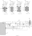
- Figures 5A to 5D show schematically different configurations for detecting the interaction between the applied changing current to the induction heating coil 12 and the at least one induction heatable element 130 according to embodiments of the present invention.
- FIG 5A schematically the configuration for detecting the interaction between the applied changing current to the induction heating coil 12 and the at least one induction heatable element 130 according to an embodiment of the present invention element according to which a first pulsating current is applied to the induction heating coil 12.
- the induction heating coil 12 is used for detecting the characteristic of the interaction between the applied first pulsating current and the at least one induction heatable element 130.
- the converting circuit 20 is also used as a detecting means 40 for detecting the characteristic of the interaction.
- the control unit 30 is configured to control the converting circuit 20 to apply the first pulsating current to the induction heating coil 12.
- the first pulsating current comprises one or more pulses with a predetermined duration with or without a period with a current of 0 or approximately 0 between them, as elaborated above.
- each short pulse of the first pulsating current creates a magnetic field in the induction heating coil 12.
- the magnetic field rapidly collapses when the pulse is turned off.
- the collapse of the magnetic field creates a current in the induction heating coil 12 as a reflected pulse.
- the transmitted pulse creates Eddy currents in the at least one heatable induction element 130 which generates its own magnetic field.
- the detecting means 40 may detect the time needed for the reflected pulse to disappear and/or the time difference between the expected reflected pulse and the actual reflected pulse as a characteristic of the interaction.
- the power supply 50 comprises a power source such as a battery (BAT) in the illustrated embodiment in figure 7 .
- the battery may be a rechargeable battery.
- the power supply 50 may alternatively or additionally comprise any other kind of power source, for example capacitor or fuel cell.
- the power source comprises a battery (BAT).
- One terminal of the battery (BAT) is connected to the input terminal (IN) of a low drop out voltage regulator (LDO).
- LDO low drop out voltage regulator
- the output terminal (OUT) of the LDO is connected to an input terminal of the control unit 30.
- the LDO has a function of regulating the output voltage of the power supply 50 even when the supply voltage is close or very close to the output voltage. In other words, the LDO can supply substantial constant voltage to the control unit 30. It may lead to the stable operation of the control unit 30. However, the LDO is optional and may be omitted.
- the output voltage of the battery is passed to the converting circuit 20 on a line 80 also called a power supply line 80.
- the converting circuit 20 converts the supplied DC current into a changing current for applying it to the induction heating coil 12 for identifying the at least one parameter. In this embodiment of the present invention the changing current is a first pulsating current.
- the induction heating coil 12 is connected to the power supply line 80 via the converting circuit 20 while the other end is connected to the ground line 81. More specifically, the power supply 50 is connected to the converting circuit 20 via a transistor T.
- the transistor T is hence arranged on the power supply line 80 and is also connected to the control unit 30 which issues appropriate control signals to the transistor T.
- the converting circuit 20 comprises at least two resistors R1 and R2, at least one operational amplifier OP1, at least one resistor Rop1 connected between the input terminals of the operational amplifier OP1, at least one transistor T1 and at least one capacitor (C1, C2 in figure 7 ).
- the conversion of the DC current into changing current is performed by controlled turning on and off of the at least one transistor T1.
- control unit 30 can switch the level of the control signal supplied to the gate of the at least one transistor T1 to switch the ON/OFF state of the at least one transistor T1. More specifically, the chopped DC current by the transistor T1 forms a square wave. The square wave is smoothed by the capacitor C2. The smoothed square wave forms a pulsating current.
- the inverting input terminal of the operational amplifier OP1 is connected to one terminal of the at least one transistor T1.
- the output terminal of the operational amplifier OP1 is connected to the control unit 30.
- the output terminal of the operational amplifier OP1 outputs a signal representing a current through the power supply line 80.
- the node between the resistors R1 and R2 is also connected to the control unit 30.
- the resistor R2 is connected to the ground line 81.
- the resistors R1 and R2 form a voltage divider circuit (R1, R2).
- the voltage divider circuit outputs a signal representing a voltage across the converting circuit 20.
- the communication between the control unit 30 and the corresponding circuit elements may be a one-way communication or a two-way communication. It is to be understood that in one-way communication one or more signals are sent from the control unit 30 to the corresponding circuit elements or from the corresponding circuit elements to the control unit 30. In a two-way communication one or more signals are sent from the control unit 30 to the corresponding circuit elements and/or from the corresponding circuit elements to the control unit 30.
- the arrow in the communication lines CL1 and CL4 indicates that the control unit 30 is sending a control signal to the transistor T and to the at least one transistor T2, while the arrow in the communication lines CL2 and CL3 indicates that a signal is sent to the control unit 30 from the node between the resistors R1 and R2 and the output of the operational amplifier OP1 respectively.
- the converting circuit 20 is used as a detecting means 40. Accordingly, when the transmitted pulse is shut off, the detecting means 40 processes signals for determining the characteristic, which may be a signal indicating the duration of the reflected pulse and/or a signal indicating the time difference between the expected reflected pulse and the actual reflected pulse as elaborated above.
- an additional switch is preferably connected to a positive pole of the capacitor C2. The additional switch turns off while the detecting means 40 processes the signals. It may enable that the operational amplifier OP1 and the voltage divider circuit (R1, R2) can monitor almost all of the current induced by the reflected pulse.
- the control unit 30 may control the additional switch.
- FIG 5B schematically an embodiment of the present invention in which one receiving coil 121 is used for sensing the interaction between the changing current and the at least one induction heatable element 130 and accordingly detecting the characteristic of this interaction.
- the receiving coil 121 is arranged coaxially or almost coaxially with the at least one induction heating coil 12 and is arranged inside the induction heating coil 12.
- the changing current is a first pulsating current applied to the induction heating coil 12 for identifying the at least one parameter.
- the power supply 50 supplies a DC current to the converting circuit 20 which converts the supplied DC current to a first pulsating current and applies the first pulsating current to the induction heating coil 12.
- the applied first pulsating current has normally low frequency.
- the frequency of the first pulsating current may be in the range of kHz.
- the receiving coil 121 picks up the generated magnetic field.
- the phase shift between the transmitted and the received frequencies may be measured for detecting a characteristic of the interaction.
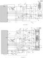
- FIG 8 Details of an exemplary circuit diagram of this embodiment of the present invention are shown with reference to figure 8 .
- the structure of the power supply 50 is the same as the structure of the power supply in the embodiment described with reference to figure 7 and therefore a detailed discussion is omitted.
- the structure of the converting circuit 20 is shown to be the same with the structure of the converting circuit 20 shown in figure 7 and a detailed discussion is therefore omitted.
- a circuit for a detecting means 40 is provided further to the converting circuit 20 in this embodiment of the present invention.
- the detecting means 40 comprises at least two resistors R3 and R4, at least one operational amplifier OP2, at least one resistor Rop2 connected between the input terminals of the at least one operational amplifier OP2, at least one transistor T2 and at least one capacitor (C3, C4 shown in figure 8 ).
- One end of the receiving coil 121 is connected to a line also called here below sensed signal supply line 83.
- the at least one operational amplifier OP2, the at least one transistor T2 and the at least two resistors R3 and R4 are connected.
- the control unit 30 receives a signal from the output of the operational amplifier OP2 and the node between the two resistors R3, R4 and based on this signal analyses the detected characteristic to thereby identify the at least one parameter of the at least one induction heatable element 130.
- the output terminal of the operational amplifier OP2 outputs a signal representing a current through the sensed signal supply line 83.
- the resistors R3 and R4 form a voltage divider circuit (R3, R4).
- the voltage divider circuit outputs a signal representing a voltage across the detecting means 40.
- control unit 30 may analyse the received signal to identify a phase shift between the magnetic field generated by the induction heating coil 12 and the magnetic field generated by the Eddy currents in the at least one induction heatable element 130 and sensed by the receiving coil 121.
- the receiving coil 121 is connected to a switching unit RE.
- the control unit 30 is connected via a switching element SE such as a bipolar transistor to the switching unit RE and sends a signal to the switching element SE to thereby switch off the at least one switching unit RE during the process of the induction heating coil 12 heating the at least one induction heatable element 130 to produce a vapour. Without this switching element RE, some magnetic field generated by the induction heating coil 12 during the induction heating process of the vapour generating substance 120 to produce a vapour is absorbed by the receiving coil 121.
- the switching element SE is supplied with a corresponding signal by the control unit 30 and the switching unit RE is thereby switched off.
- the switching unit RE may be a relay. The relay can completely isolate the detecting means 40 and the receiving coil 121 from the induction heating coil 12. In this way with a simple construction the efficiency of the heating process may be improved.
- the switching element SE is supplied with a corresponding signal by the control unit 30 and the switching unit RE is thereby switched on.
- a first negative line 82 is connected to the ground (GND) of the ground line 81. In such way, a closed circuit is formed.
- the detection means 40 and the receiving coil 121 can output the transmitted pulses.
- the first pulsating current is applied to the receiving coil 121 by the detecting means 40. While the receiving coil 121 is outputting the transmitted pulses, the switching unit RE is closed.
- Figure 5C shows an embodiment of the present invention in which the receiving coil 121 is arranged coaxially or approximately coaxially with the induction heating coil 12 and outside the induction heating coil 12. It is to be understood that the circuit diagram for this embodiment is the one shown in figure 8 .
- the receiving coil 121 being arranged coaxially inside or coaxially outside the induction heating coil 12 may be arranged for example in the upper part of the induction heating coil 12 as it is shown in figure 6A and figure 6B . However, this is not limiting to the present invention and the receiving coil 121 may be arranged in the lower part of the induction heating coil 12 or in the middle portion (middle part) of the induction heating coil 12.
- the receiving coil 121 is arranged in a portion of the induction heating coil 12 or along the induction heating coil 12 such that one or more the windings of the receiving coil 121 are arranged between one or more the windings of the induction heating coil 12.
- FIG 5D a further embodiment of the present invention in which two receiving coils 121, 122 are used (first receiving coil 121 and second receiving coil 122).
- the first receiving coil 121 is arranged coaxially or approximately coaxially with the induction heating coil 12; and the second receiving coil is arranged coaxially or approximately coaxially with the induction heating coil 12.
- the first receiving coil 121 may be arranged in the upper part of the induction heating coil 12 and the second receiving coil 122 may be arranged in the bottom part of the induction heating coil 12.
- This configuration is schematically shown in figure 6C .
- the first receiving coil 121 and the second receiving coil 122 may be arranged coaxially inside or coaxially outside of the induction heating coil 12 or one or more windings of the first receiving coil 121 and/or the second receiving coil may be between one or more windings of the induction heating coil 12.
- Each one of the first receiving coil 121 and the second receiving coil 122 may at least in part overlap with the induction heating coil 12 or may be arranged at a predetermined distance from the respective ending of the induction heating coil 12.
- FIG. 9 A more specific exemplary circuit diagram for the embodiment of the present invention in which the vapour generating device 1 comprises a first receiving coil 121 and a second receiving coil 122 is shown in figure 9 .
- the structure of the power supply 50 is the same as in the previously described embodiments with respect to figured 7 and 8.
- the structure of the converting circuit 20 is the same as the structure of the converting circuit 20 of the embodiment described with respect to figure 8 .
- one end (first end) of each one of the first receiving coil 121 and second receiving coil 122 is connected to a corresponding signal detection line 83, 85 via at least one capacitor (C6, C4) to the terminal of at least one switching element T3, T2.
- the switching element T3, T2 may be a transistor T3, T2.
- Each one of the first receiving coil 121 and second receiving coil 122 is connected to a corresponding at least one switching unit RE1, RE2.
- the structure and the control of each of the at least one switching units RE1, RE2 is the same as in the embodiment described with reference to figure 8 .
- the detecting means 40 comprises further at least one operational amplifier 401 which a non-inverting input terminal is connected with one of the first receiving coil 121 (first end of the first receiving coil 121) or the second receiving coil 122 (first end of the second receiving coil 121) and an inverting input terminal is connected with other of the first receiving coil 121 or the second receiving coil 122.
- the non-inverting input terminal of the operational amplifier 401 is connected to the first end of the first receiving coil 121 and the inverting input terminal of the operational amplifier 401 is connected to the first end of the second receiving coil 122, however, the opposite configuration is also possible.
- the detecting means 40 comprises further a sine phase detector 402 connected with an output terminal of the operational amplifier 401, a cosine phase detector 403 connected with the output terminal of the operational amplifier 401, a first band pass filter 404, which is connected with the sine phase detector 402, configured to output magnetization current and a second band pass filter 405, which is connected with the cosine phase detector 403, configured to output Eddy current.
- the control unit 30 is configured to identify the at least one parameter of the at least one induction heatable element 130 based on the magnetization current and the Eddy current.
- the magnetization current is the current induced in each one of the first receiving coil 121 and the second receiving coil 122 based on the magnetic field generated by the Eddy currents generated in the at least one induction heatable element 130. Accordingly, in this embodiment of the present invention the characteristic of the interaction may be based on the magnetization current and the Eddy current.
- the detection means 40 and at least one of the first receiving coil 121 and the second receiving coil 122 can output the transmitted pulses.
- the first pulsating current is applied to the first receiving coil 121 and/or the second receiving coil 122 by the detecting means 40. While the first receiving coil 121 and/or the second receiving coil 121 is outputting the transmitted pulses, the switching unit (RE1, RE2) is closed.
- the converting circuit 20 is configured to convert a direct current supplied from the power supply 50 into a first pulsating current, as also elaborated with respect to figure 7 .
- the converting circuit 20 may be or may comprise an inverter circuit configured to convert a direct current supplied from the power supply 50 into a first alternating current.
- the different configurations for detecting the interaction shown in figures 5B, 5C and 5D apply as well.
- the vapour generating device 1 may further comprise at least one third receiving coil 123, said at least one third receiving coil being arranged between the first receiving coil 121 and the second receiving coil 122.
- the arrangement of the induction heating coil 12, the first receiving coil 121, the second receiving coil 122 and the third receiving coil 123 in this embodiment of the present invention is schematically shown in figure 6D .
- the detecting means 40 may comprise further circuit elements for detecting the characteristic.
- Figure 6D shows that only one third receiving coil 123 is arranged between the first receiving coil 121 and the second receiving coil 122, however, more than one third receiving coil 123 may be arranged between the first receiving coil 121 and the second receiving coil 122.
- the windings of the one or more receiving coil 121 are normally electrically isolated from the windings of the induction heating coil 12.
- the detecting means 40 may be configured to detect the characteristic of the interaction either during the insertion of the consumable article 100 in the heating compartment 11 or after the consumable article 100 has taken its final position in the heating compartment 11.
- control unit 30 may be configured to recognize that the consumable article 100 is being inserted in the heating compartment 11 and control the converting circuit 20 to apply a first alternating or a first pulsating current to the induction heating coil 11.
- control unit 30 may be configured to recognize that that the consumable article 100 is being inserted in the heating compartment 11 by way of a signal generated when the access means 13 are operated by the user. Based on this signal the control unit 30 may control the converting circuit 20 to apply the first alternating current or first pulsating current to the induction heating coil 12.
- control unit 30 may be configured to start processing to identify the at least one parameter of the at least one induction heatable element 130 a predetermined time after start of control of the converting circuit 20 to apply the first alternating current or first pulsating current to the induction heating coil 12.
- control unit 30 may be configured to control the converting circuit 20 to apply the first alternating current or the first pulsating current to the induction heating coil 12 when it is detected that the access means 130 are operated by the user or when it is detected that the consumable article 100 has taken the final position in the heating compartment 12 and hence is not moving any more.
- the control unit 30 may be configured to start processing to identify the at least one parameter of the at least one induction heatable element 130 a predetermined time after start of control of the converting circuit 20 to apply the first alternating current or first pulsating current to the induction heating coil 12.
- the predetermined time may take into account settling down the change of the induced electromotive force in the system.
- control unit 30 starts processing to identify the at least one parameter of the at least one induction heatable element after the change of the induced electromotive force in the system settles down.
- the degree of insertion can be disregarded.
- the at least one parameter can be identified with a higher precision.
- control unit 30 may be configured to control the converting circuit 20 to apply the first alternating current or the first pulsating current with a single frequency or with different frequencies. Applying the first alternating current or the first pulsating current with different frequencies enables that it is distinguished between different materials of the at least one induction heatable element 130. Higher frequencies are generally more suitable to be applied when the material of the at least one induction heatable element 130 is a metal or a metal alloy composition with lower conductivity. On the other hand, lower frequencies are generally more suitable to be applied when the material of the induction heatable element 130 is a metal or metal alloy composition with higher conductivity.
- the control unit 30 may be further configured to control the converting circuit 20 to apply the different frequencies of the first alternating current or the first pulsating current in a subsequent order.
- the control unit 30 may be configured to apply the first alternating current or first pulsating current by changing step-wise or continuously in increasing or decreasing manner the frequency of the applied first alternating current or first pulsating current.
- the frequency of first alternating current or the first pulsating current can be controlled by a switching frequency of the transistor T1.
- the control unit 30 may be further configured to control the converting circuit 20 to apply the first alternating current or the first pulsating current by applying a plurality of pulses with a predetermined duration or applying continuously the first alternating current or the first pulsating current for a predetermined duration.
- the first pulsating current being applied by applying a plurality of pulses may mean that within each pulse one or more pulses are applied.
- the above may enable that the richness of the interaction between the at least one induction heatable element 130 and the first alternating current or the first pulsating current is enhanced, which may enable that more details of the interaction are detected.
- the vapour generating device 1 comprises at least one receiving coil 121, 122, 123
- the detecting means 40 detects the characteristic by using only the induction heating coil 12.
- the control unit 30 may be configured to select the most suitable detection principle.
- control unit 30 may be configured to select at least one setting for controlling the heating of the at least one induction heatable element 130 by the induction heating coil 12 based on the identified at least one parameter of the induction heatable element.
- the at least one parameter may be at least one of length, position within the consumable article, variance from a standard shape, material alloy variation and degree of oxidation.
- the control unit 30 may be running an algorithm that selects at least one setting for optimizing one or more setting of the vapour generating device 1 for the specific inserted and recognized consumable article 100 and accordingly for the specific inserted and recognized at least one induction heatable element 100.
- the algorithm and any further information that may be needed by the control unit 30 may be stored in the above-described memory.
- the algorithm may therefore change the settings of the vapour generating device 1 in order to maximize the device efficiency and the sensorial experience for the user.
- the algorithm may maximize the generation of the Eddy currents in the at least one induction heatable element 130 at a given power supplied to the induction heating coil 12. Accordingly, the vapour generating device 1 may tune its settings to optimize the heating for the specific inserted and recognized at least induction heatable element 130.
- a look up table may be stored in the above-described memory which associates settings for the vapour generating device 1 with at least one parameter of the at least one induction heatable element 130 and the control unit may choose the most optimal setting.
- the control unit 30 may be configured to calculate the optimal settings of the vapour generating device 1 in order to maximize the generation of the Eddy currents at least induction heatable element 130 at a given power supplied to the induction heating coil 12.
- the selected at least one setting for controlling the heating of the induction heatable element 130 may be at least one of frequency or frequencies, amplitude and the ramp-up speed of the changing current for heating the vapour generating substance 120 to produce a vapour. Accordingly, the algorithm may adjust the settings of the vapour generating device 1 in accordance with the selected at least one setting.
- adjustment of the settings include but are not limited to the following: adjusting the induction carrier frequency to best resonate with the susceptor 130, increasing the induction intensity (carrier amplitude) to reach the desired Eddy currents intensity, decreasing the ramp-up speed if the susceptor 130 is not centred within the vapour generating substance 120 to allow heat to diffuse into the whole vapour generating substance 120 or if the susceptor 130 is oxidized, for example due to long storage or storage not being accordance with specifications as set for example by the manufacturer.
- the vapour generating device 1 may comprise further moving means for moving the induction heating coil 12 along the first direction.
- the selected at least one setting for controlling the heating of the induction heatable element 130 may comprises a distance for moving the induction heatable coil 12 along the first direction. Accordingly, the position of the induction heatable coil 12 in the heating compartment 11 and accordingly the position of the induction heating coil 12 with respect to the at least one induction heatable element 130 of the inserted consumable article 100 may be adjusted to the specific position of the at least one induction heatable element 130 in the heating compartment 11.
- Step S100 is a step of application of a first alternating current or a first pulsating current to the induction heating coil 12.
- Step S200 is a step of identification of at least one parameter of the at least one induction heatable element 130 positioned in the heating compartment 11 based on the interaction between the first alternating current or the first pulsating current and the at least one induction heatable element.
- Step S300 is a step of selecting at least one setting for controlling the heating of the at least one induction heatable element 130 by the induction heating coil 12 based on the identified at least one parameter of the induction heatable element 130.
- one or more the settings of the vapour generating device 1 are optimized for the specific at least one induction heatable element 130 introduced in the vapour generating device 1 it is possible to achieve lower costs for manufacturing of induction heatable elements and accordingly of consumable articles due to better manufacturing yield since higher number of produced consumable articles may be used despite differences between the induction heatable elements of different consumable articles.
- the testing costs may be decreased since highly precise diagnostic for identifying small deviations from standard values for the induction heatable elements may not be needed.
- the device efficiency may be increased, the battery duration at given battery size may be increased since the heating may be optimized and a better sensorial experience for the user can be provided since the settings of the vapour generating device are optimized for the specific inserted and recognized at least one induction heatable element 130.
Abstract
There is provided a vapour generating device comprising: a heating compartment extending along a first direction;an induction heating coil arranged around the heating compartment and extending along the first direction and being arranged to inductively heat at least one induction heatable element being positioned in the heating compartment to thereby heat a vapour generating substance to produce a vapour; a power supply; a converting circuit configured to convert a direct current supplied from the power supply into an alternating current or a pulsating current and apply the alternating current or pulsating current to the induction heating coil; and a control unit configured to:- control the converting circuit to apply a first alternating current or a first pulsating current to the induction heating coil;- identify at least one parameter of the at least one induction heatable element positioned in the heating compartment based on an interaction between the first alternating current or the first pulsating current and the at least one induction heatable element; and- select at least one setting for controlling the heating of the at least one induction heatable element by the induction heating coil based on the identified at least one parameter of the at least one induction heatable element.
Description
- The present invention relates to a vapour generating device and in particular relates to tuning of settings of a vapour generating device for inductively heating a vapour generating substance.
- In the recent years devices which heat rather than burn or cause combustion of a substance to generate a vapour for inhalation by a user have become increasingly popular.
- Such devices, commonly named vapour generating devices, are commonly handheld device. In general, such handheld vapour generating device may be said to belong to two groups: electronic cigarettes and tobacco vapour devices. Electronic cigarettes also called e-cigarettes, vaporizers or cig-a-likes are vapour generating device that simulate tobacco smoking and do not contain tobacco. These devices generate inhalable vapour by heating a liquid solution containing flavour releasing substance. An example of flavour releasing substance is nicotine. The liquid solution is also called e-liquid.
- The tobacco vapour devices, also known as heated tobacco products, on the other hand contain tobacco that is heated but not burned to create an inhalable vapour.
- In general, such e-liquid used in electronic cigarettes or tobacco used in tobacco vapour products may be called a vapour generating substance. Normally, the vapour generating substance is placed in a container, that may also be called cartridge or tobacco stick, that can be inserted in and removed from the vapour generating device by the user. Therefore, the container in which the vapour generating substance is placed is a consumable article and is also called a consumable.
- Regarding the heating of the vapour generating substance in the consumable article, different vapour generating device may apply different approaches. One simple approach is based on electrical heating also known as resistive heating and involves providing an electrical power to a heating element which is in direct or indirect contact with the vapour generating substance. When the user activates the vapour generating device electrical power is provided to the heating element. The heating element is heated, which in turn heats the vapour generating substance to generate vapour that can be inhaled by the user.
- Other approach is based on induction heating. In this approach an induction heating coil is provided in the vapour generating device and in addition at least one induction heatable element is provided in the vapour generating device or more commonly in the consumable article. The induction heatable element is also called a susceptor. The susceptor may be in direct or an indirect contact with the vapour generating substance or may be arranged in the vicinity of the vapour generating substance. When changing electric current is provided to the induction heating coil, an electromagnetic field (EM) is generated. The susceptor being placed in the electromagnetic field absorbs the electromagnetic energy and converts it to heat. With the generated heat the vapour generating substance is heated and vapour is generated that can be inhaled by the user.
- Very often the susceptor is placed in the consumable article and arranged such that it is surrounded by the vapour generating substance. In other words, the susceptor is arranged such that it is buried completely or at least partly in the vapour generating substance. This way of providing the susceptor requires highly precise control of the position of the susceptor within the consumable article in order that the susceptor absorbs optimally the generated electromagnetic field to thereby optimally heat the vapour generating substance to produce vapour. However, since a different susceptor is placed in each consumable article it is expected that small differences may exist between the different susceptors due to, for example, manufacturing tolerances of the different susceptors. By way of example, such small differences may exist with respect to the shape or the material such as metal alloy composition of the susceptor or the position of the susceptor in the consumable article.
- Therefore, during the manufacturing of the consumable article it is needed that a precise diagnostic, for example an x-ray scanner or similar, is used in the manufacturing line to check whether the susceptor in the consumable article is within the prescribed specifications. The prescribed specifications may include specifications as to the position, size, shape, thickness, material composition and similar of the susceptor. For this, normally, the susceptor position, size, material, thickness and/or shape are measured. As a result, some of the susceptors and consequently some of the consumable articles may be rejected which decreases the production yield of consumable articles and impacts the product costs as well as results in higher manufacturing costs and higher manufacturing testing costs. In addition, the time between production of the susceptor and its actual use has also influence on the properties of the susceptor since this storage time as well as the storage conditions influences the rusting or the oxidation degree of the susceptor.
- Therefore, there is a need for providing for using as much as possible produced consumable articles to thereby increase as much as possible the production yield as well as reducing the manufacturing costs and the manufacturing test costs of consumable articles.
- The mentioned problems and objects are met by the subject-matter of the independent claims. Advantageous embodiments are defined in the dependent claims.
- According to one aspect of the present invention there is provided a vapour generating device comprising: a heating compartment extending along a first direction; an induction heating coil arranged around the heating compartment and extending along the first direction and being arranged to inductively heat at least one induction heatable element being positioned in the heating compartment to thereby heat a vapour generating substance to produce a vapour; a power supply; a converting circuit configured to convert a direct current supplied from the power supply into an alternating current or a pulsating current and apply the alternating current or pulsating current to the induction heating coil; and a control unit configured to:
- control the converting circuit to apply a first alternating current or a first pulsating current to the induction heating coil;
- identify at least one parameter of the at least one induction heatable element positioned in the heating compartment based on an interaction between the first alternating current or the first pulsating current and the at least one induction heatable element; and
- select at least one setting for controlling the heating of the at least one induction heatable element by the induction heating coil based on the identified at least one parameter of the at least one induction heatable element.
- Embodiments of the present invention which are presented for better understanding the inventive concept of the present invention, but which are not to be seen as limiting the present invention, will now be described with reference to the figures in which:
- Fig. 1A
- shows a schematic view of the vapour generating
device 1 according to the embodiment of the present invention; - Fig. 1B
- shows a schematic view of a
consumable article 100 to be inserted in the vapour generatingdevice 1 of the embodiment of the present invention; - Fig. 1C
- shows a schematic view of the vapour generating
device 1 according to the embodiment of the present invention with an inserted consumable; - Fig. 2A
- shows a schematic view of the functional components of the vapour generating
device 1 of the embodiment of the present invention. - Fig. 2B
- shows a schematic view of the functional components of the vapour generating
device 1 of the embodiment of the present invention with theconsumable article 100 inserted into thevapour generating device 1. - Fig. 3A
- shows a schematic view of a part of the vapour generating
device 1 according to the embodiment of the present invention. - Fig. 3B
- shows schematically examples of a structure of a
consumable article 100 to be used with thevapour generating device 1 according to the embodiment of the present invention. - Fig. 4A, 4B
- show schematically the principles of interaction between an applied changing current to the induction heating coil and the at least one induction heatable element according to the embodiment of the present invention.
- Fig. 5A to 5D
- show schematically different configurations for detecting the interaction between an applied changing current to the induction heating coil and the at least one induction heatable element according to the embodiments of the present invention.
- Fig. 6A to 6D
- show schematically examples of a part of the vapour generating device according to the embodiments of the present invention.
- Fig. 7, 8 and 9
- show schematically a circuit diagram of components of the vapour generating device according to the embodiments of the present invention.
- Fig. 10
- is a flow diagram of the steps of controlling the vapour generating device according to the embodiment of the present invention.
- The present invention proposes automatically detecting the variability of the susceptor arranged in the consumable article, said consumable article comprising a vapour generating substance to be heated by the susceptor to produce vapour. The term variability is to be understood as a variance in parameters of the susceptor from parameters being defined as standard parameters. The standard parameters may be defined by the manufacturer of the vapour generating device and/or of the consumable article. The parameters may include one or more of a shape of the susceptor, size of the susceptor such as its length and/or thickness, position of the susceptor within the consumable article, material composition of the susceptor such as for example material alloy variation of the susceptor, degree of oxidation and/or similar.
- The present invention proposes further allowing the vapour generating device to tune its settings thereby optimizing them for the specific inserted susceptor. This results in higher production yield of consumable articles since the vapour generating device can accept larger tolerances between susceptors of different consumable articles, and further results in reduced manufacturing costs and reduced manufacturing tests costs as well as increased device efficiency and increased sensorial experience for the user since the settings of the vapour generating device are optimized for the specific inserted susceptor.
-
Figure 1A shows a schematic view of avapour generating device 1 according to an embodiment of the present invention. - The
vapour generating device 1 according to the embodiment of the present invention may be a handheld device. Thevapour generating device 1 may have, as shown infigure 1A a pebble-like shape. However, the shape of thevapour generating device 1 is not limited to a pebble-like shape and other shapes are also possible, for example a cylindrical shape. Thevapour generating device 1, as it is shown infigure 1A , comprises ahousing 2. Thevapour generating device 1, as shown infigure 1A may further comprise an access portion. The access portion is arranged normally but not limited to in the top end part of thevapour generating device 1 and may comprise access means 13 for opening and closing an opening to a heating compartment of thevapour generating device 1. In the heating compartment, via the access portion, a user may place at least one consumable article 100 (example being shown infigure 1B ) comprising vapour generating substance. In the heating compartment the vapour generating substance is heated by a power supplied by a power supply. - The
housing 2 of thevapour generating device 1 may have a smooth outer surface which together with the pebble-like shape provides a physical ergonomic advantage for the user. Thehousing 2 houses at least the mentioned heating chamber and houses further components of thevapour generating device 1 as elaborated below. The material of thehousing 2 may be a metal or a polymer-based material or a composition of both. - The user can place a consumable article 100 (example being shown in
figure 1B ) containing a vapour generating substance into the heating chamber by, for example, operating the access means 13 for opening and closing the opening to the heating compartment of thevapour generating device 1. - The access means 13 may comprise in one embodiment of the present invention, for example, a lid that can at least be partly removed from the
housing 2 to thereby expose the opening of the heating compartment. In other embodiment of the present invention the access means 13 may comprise, for example, a slider. Theslider 13 may be moved between two positions such as opened position and closed position for exposing and covering the opening of the heating compartment. In still other embodiment of the present invention the access means may comprise, for example, a trap door. - As it is further shown in
figure 1A thevapour generating device 1 may comprise on the outer side of thehousing 2 indication/operation means 3. The indication/operation means 3 may comprise input means (comprising for example one or more buttons or one or more touch buttons on a display) for controlling, for example turning on or off thevapour generating device 1. The indication/operation means 3 may in addition or alternatively comprise other means, for example one or more light emitting devices and/or a display for indicating different information to the user such as the current status of the power supply, for example the remaining amount of charge in the power supply and/or the amount of consumption of the vapour generating substance in theconsumable article 100 and similar. -
Figure 1B shows a schematic view of theconsumable article 100 to be inserted in thevapour generating device 1 according to the embodiment of the present invention. Theconsumable article 100 may be a stick comprising tobacco and/or tobacco material and/or other suitable substance that is heated but not burned in the heating compartment to create an inhalable vapour. The term "vapour" may be used interchangeably with the term "aerosol". - The
consumable article 100 may have an elongated form, for example a cylindrical form as shown infigure 1B . Theconsumable article 100 may be partitioned in two parts: thefirst part 110 may be a filter portion or may comprise a filter portion, while in thesecond part 150 the vapour generating substance is arranged as will be elaborated in more details further below. In thesecond part 150 also at least one induction heatable element also called susceptor is arranged. -
Figure 1C shows a schematic view of thevapour generating device 1 according to the embodiment of the present invention with an insertedconsumable article 100. As it is seen infigure 1C , when theconsumable article 100 is inserted in thevapour generating device 1 the first part of theconsumable article 100 is entirely or at least partly extending outside of thevapour generating device 1 so that the user can thereby inhale the generated vapour by placing this part at least partly in the mouth. As further shown infigure 1C , when theconsumable article 100 is inserted in thevapour generating device 1 the access means 13 are moved to expose the opening of the heating compartment so that the user can insert theconsumable article 100 in the heating compartment. - It is to be understood that the
consumable article 100 to be used with thevapour generating device 1 of the present invention does not need to comprise thefirst part 110 which is a filter portion or may comprise a filter portion. In other words, theconsumable article 100 may only comprise thesecond part 150 in which the vapour generating substance is arranged. In such case, for example thevapour generating device 1 may comprise a mouthpiece or other suitable part through which the user can inhale the generated vapour. However, in such a case a mouthpiece or other part is not obligatory. In addition, in embodiments of the present invention in which theconsumable article 100 comprises thefirst part 100, thevapour generating device 1 may still comprise a mouthpiece. -
Figure 2A shows a schematic view of the functional components of thevapour generating device 1 of the embodiment of the present invention.Figure 2B shows a schematic view of the functional components of thevapour generating device 1 of the embodiment of the present invention with theconsumable article 100 being inserted in thevapour generating device 1. - The
heating compartment 11 mentioned above may be such that the user can place oneconsumable article 100 at a time or the user may place more than oneconsumable article 100 at a time. In the following, it will be assumed that theheating compartment 11 is such that the user can place oneconsumable article 100 at a time in theheating compartment 11. Theheating compartment 11 may also have a cylindrical form as well as theconsumable article 100. The form of theconsumable article 100 and the form of theheating chamber 11 are not to be seen as limiting to the present invention. Theheating compartment 11 extends along a first direction, which infigure 2A is the up-down direction. The user places theconsumable article 100 in theheating compartment 11 by operating the access means 13 to expose the opening of theheating compartment 11.Figure 1B shows a schematic view of thevapour generating device 1 with the insertedconsumable 100. - For inserting the
consumable article 100, in this embodiment of the present invention, the user places the access means 13 in the opened position and inserts the consumable 100 in theheating compartment 11 via the thereby exposed opening. By way of example, when the access means 13 is a slider the user slides the slider to the side as shown infigure 1C and figure 2B (along the left-right direction infigure 2A ) so that it is in the opened position (figure 2B ). Theheating compartment 11 has the above-mentioned opening at one end (up direction infigure 2A ) and further comprises a base portion at the opposite end (down direction infigure 2A ). Theheating compartment 11 is therefore arranged to receive, in use, via the opening, theconsumable article 100 to be heated by induction heating as elaborated later. "In use" is to be understood in the sense that the user may at least insert theconsumable article 100 in theheating compartment 11 via the opening by operating the access means 13. In use, the user may in addition operate thevapour generating device 1 to heat the vapour generating substance arranged in theconsumable article 100. - When the
consumable article 100 is completely inserted into theheating compartment 11 the vapour generating substance and the at least one induction heatable element are arranged in theheating compartment 11. An example of the arrangement for an exemplary at least one inductionheatable element 130 is shown infigure 2B . The user may know that theconsumable article 100 is completely inserted in theheating compartment 11 by, for example, perceiving that theconsumable article 100 abates against the base portion of theheating compartment 11. In a further embodiment of the present invention a member may be provided on theconsumable article 100 that ensures that theconsumable article 100 is inserted in theheating compartment 11 such that thevapour generating substance 120 and the at least one inductionheatable element 130 are arranged in theheating compartment 11. - The
heating compartment 11 may be in gaseous connection with an air inlet and an air outlet (not shown in the figures) formed in thehousing 2. This allows air to be drawn by the user through the air outlet (inlet). - The
vapour generating device 1 according to different embodiments of the present invention with theconsumable article 100 inserted in theheating compartment 11 may also be called a vapour generating system. In other words, a vapour generating system according to the present invention comprises thevapour generating device 1 according to different embodiments of the present invention and theconsumable article 100 described in the different embodiments of the present invention. By way of example, such system, for an exemplary configuration of the at least one inductionheatable element 130 and thevapour generating substance 120 is shown schematically infigure 2B . - The
vapour generating device 1 comprises further aninduction heating coil 12. Theinduction heating coil 12 is arranged to extend along the first direction. Accordingly, theinduction heating coil 12 is arranged to extend along theheating compartment 11. Theinduction heating coil 12 may be seen as being wrapped around theheating compartment 11. By way of example, in the embodiment of the present invention in which theheating compartment 11 has a cylindrical form, theinduction heating coil 12 being wrapped around theheating compartment 11 may also have a cylindrical form. Theheating compartment 11 is defined thus radially inward of theinduction heating coil 12 and has a wall around a radially inner side of theinduction heating coil 12 around which wall theinduction heating coil 12 is wrapped. However, it is to be understood that it is not obligatory that theheating compartment 11 has a wall, since also the space inside theheating coil 12 may represent aheating compartment 12. - The
induction heating coil 12 may have such a length such that thevapour generating substance 120 or at least the at least one inductionheatable element 130 is completely or partly within the part of theheating compartment 11 along which theinduction heating coil 12 extends when theconsumable article 100 is completely inserted in theheating compartment 11. This is shown in more details infigure 3A . There is shown infigure 3A that theinduction heating coil 12 is arranged around theheating compartment 11 and extends along theheating compartment 11 such that the at least oneheatable element 130 which in the embodiment shown infigure 3A has an elongated shape is at least partly within the part of theheating compartment 11 along which theinduction heating coil 12 extends. In other embodiments of the present invention more than oneinduction heating coil 12 may be arranged along theheating compartment 11 to thereby heat different portions of thevapour generating substance 120. - The
induction heating coil 12 is arranged to inductively heat the at least one inductionheatable element 130 being positioned in theheating compartment 11 to thereby heat thevapour generating substance 120 to produce a vapour. When changing electric current is provided to theinduction heating coil 12, an electromagnetic field (EM) is generated. The at least one inductionheatable element 130 being positioned in theheating compartment 11 absorbs the electromagnetic energy and converts it to heat. With the generated heat the vapour generating substance is heated and vapour is generated that can be inhaled by the user. Since the magnetic field component of the electromagnetic field is predominantly responsible for the interaction with the susceptor, in the following description the terms electromagnetic field and magnetic field are used interchangeably with each other. The user may inhale the produced vapour. For example, the user may inhale the produced vapour through thefirst portion 110 of theconsumable article 100. In the embodiments of the present invention in which thevapour generating device 1 comprises a mouthpiece or similar the user may inhale the produced vapour via the mouthpiece or similar. -
Figure 3B shows details of the possible structure of theconsumable article 100 according to embodiments of the present invention. There is shown infigure 3B aconsumable article 100 in which thefirst part 110 is a filter portion or comprises a filter portion, however this is not mandatory. In thesecond part 150 of theconsumable article 100 thevapour generating substance 120 and the at least one inductionheatable element 130 are arranged. In this embodiment of the present invention the at least one inductionheatable element 130 is buried into thevapour generating substance 120. In the left-hand side offigure 3B theconsumable article 100 comprises one inductionheatable element 130 having a rectangular shape (plate-like shape) and being buried into thevapour generating substance 120. The inductionheatable element 130 being buried into thevapour generating substance 120 is to be understood as the inductionheatable element 130 being at least partly covered by thevapour generating substance 120. In this embodiment of the present invention, the at least one inductionheatable element 130 is a rectangular thin plate (plate-shaped) buried inside thevapour generating substance 120 which may be shaped into a cylindrical form. In this embodiment of the present invention theconsumable article 100 comprises one plate-shaped induction heatable element, however this is not limiting and more than one plate-shaped inductionheatable elements 130 arranged parallel to each other may be provided. The thickness of the inductionheatable element 130 may be in the range of a micrometre to one or more millimetres. Additionally, or alternatively, other shape (e.g., cylindrical shape) induction heatable element can be employed. - The
vapour generating substance 120 is a flavour-release medium which may be any material or combination of materials which can be heated to release a vapour for inhalation by the user. The flavour-release medium may be tobacco or a tobacco material and may be impregnated with a vapour-forming medium such as propylene glycol or glycerol. However, this is not limiting to the present invention and thevapour generating substance 120 may comprise any flavour-release substance in solid or liquid form which may be heated to produce a vapour. The vapour generating substance may comprise more than one flavour-release medium. - By way of example, the
vapour generating substance 120 may comprise a granulated material which is shaped into a suitable shape. Suitable may be understood in the sense of a shape that is suitable for the specificconsumable article 100 in terms of, for example, its form. By way of further example, thevapour generating substance 120 may be shaped in a cylindrical shape in this embodiment of the present invention. However, the shape of thevapour generating substance 120 is not limited to a cylindrical shape. In other words, thevapour generating substance 120 may be shaped in a different shape when solid or may be placed within a container with a suitable shape when liquid. - In other embodiments of the present invention the
consumable article 100 may comprise more than one inductionheatable elements 130 with a different shape than a rectangular thin plate. For example, theconsumable article 100 may comprise plurality of inductionheatable elements 130 each in the form of a particle as shown in the right-hand side offigure 3B . The particles (induction heatable elements) may have different shape, such as spheres, platelets, rectangles or similar. The particles may be distributed throughout thevapour generating substance 120 in a regular pattern or irregular pattern. Of course, combination of the left-hand side and the right-hand side offigure 3B can be also employed. - The at least one induction
heatable element 130 and thevapour generating substance 120 may be in a direct or indirect contact. The indirect contact may mean that a further material is present between the at least one inductionheatable element 130 and thevapour generating substance 120. For example, a material (also called intermediate material) promoting better adhesion of thevapour generating substance 120 on the surface of the at least one inductionheatable element 130 may be present between the at least one inductionheatable element 130 and thevapour generating substance 120. The direct contact may mean that thevapour generating substance 120 adheres to the surface of the at least one inductionheatable element 130 without an intermediate material. - The material of the at least one induction
heatable element 130 is a material, such as metal, that can interact with an electromagnetic field. In use, when theconsumable article 100 is inserted in theheating compartment 11 thevapour generating substance 120 is heated by induction heating. More specifically, a changing (varying) current, such as an alternating current is applied to theinduction heating coil 12 and a changing magnetic field is generated. Since the at least one inductionheatable element 130 is completely or partly within the part of theheating compartment 11 along which theinduction heating coil 12 extends, the at least one inductionheatable element 130 is completely or at least partly within the generated changing magnetic field. The changing magnetic field generates Eddy currents in the at least one inductionheatable element 130. The at least one inductionheatable element 130 has electrical resistance to the generated Eddy currents and hence the flow of the Eddy currents generates Joule heat within the at least one inductionheatable element 130. The heated at least one inductionheatable element 130 heats thereby thevapour generating substance 120 to produce vapor. The material of the inductionheatable element 130 is chosen such that it is heated at least up to a temperature at which the generated heat in the at least one inductionheatable element 130 can heat the vapour generating substance to a temperature at which vapour generation occurs. If the metal of the at least one inductionheatable element 130 is magnetic than a heating due to hysteresis effect in such magnetic susceptor is also possible. - In one embodiment of the present invention, the material of the at least one induction
heatable element 130 is a high temperature superconductor. - In the above-described embodiments of the present invention the at least one induction
heatable element 130 is buried in thevapour generating substance 120. However, it is also possible that the at least one inductionheatable element 130 is arranged around thevapour generating substance 120 with or without an intermediate material or is arranged at a distance from thevapour generating substance 120. - As further shown in
figure 2A , thevapour generating device 1 comprises further apower supply 50. Thepower supply 50 may comprise a battery for example a rechargeable battery (BAT) (e.g., lithium-ion secondary battery) or any other kind of power source (e.g., capacitor or fuel cell) suitable to supply electric current to theinduction heating coil 12. The power supply normally supplies a direct current. Thepower supply 50 is electrically connected to theinduction heating coil 12 via a convertingcircuit 20. The convertingcircuit 20 is configured to convert the direct current supplied from thepower supply 50 into an alternating current or a pulsating current and apply the alternating current or pulsating current to theinduction heating coil 12. The alternating current and the pulsating current may be commonly referred to as a changing current or a varying current in the present description. Details of the convertingcircuit 20 in an embodiment of the present invention will be elaborated later with respect tofigure 7 ,figure 8 and figure 9 . - It is to be understood that a pulsating current is a periodic current which changes in value but in difference to alternating current does not change in direction. The pulsating current therefore comprises a plurality of pulses. The pulses may be continuous but there may also exist a period between the pulses in which the value of the current is approximately 0. Here, it is to be understood that the term "approximately" is used to account for small variations of the current around the value of 0 caused by tolerances of the electronic elements in the converting
circuit 20 for example. The pulses may be sinusoidal (and hence be expressed by sinusoidal function), however, this is not limiting to the present invention and other function describing the pulses is also possible. By way of example the pulses may also be rectangular. - As it is shown in
figure 2A thevapour generating device 1 comprises further acontrol unit 30. Thecontrol unit 30 is any suitable unit or comprises any suitable unit such as computer processing unit that can perform computer processing. The control unit 30 (also called controller) may be for example a microcontroller unit (MCU) and/or micro processing unit (MPU). Further, thecontrol unit 30 may comprise storage means, such as a memory, not shown in the figure. The memory may also be a separate unit from the control unit also placed inside thehousing 2. The memory may store different information needed for the processing by thecontrol unit 30, as will be elaborated further below. Further, the memory may store computer program (code) comprising instructions which, when the program is executed by thecontrol unit 30, cause thecontrol unit 30 to carry out the processing of the embodiment of the present invention as will be elaborated further below. Thecontrol unit 30 may comprises a communication interface. The communication interface may support Bluetooth Low Energy (BLE). - The
control unit 30 is configured to control the convertingcircuit 20 to convert a direct current supplied from the power supply into an alternating current or a pulsating current and apply the alternating current or pulsating current to theinduction heating coil 12. For example, thecontrol unit 30 may be configured to control the elements of the convertingcircuit 20 described further below with reference tofigures 7 ,8 and 9 by controlling the switch frequency, the on/off time and similar of the corresponding components. - The alternating current or a pulsating current may be an alternating current or a pulsating current to be applied to the
induction heating coil 12 for inductively heating the at least one inductionheatable element 130 to thereby heat thevapour generating substance 120 to produce a vapour for generation. Further, the alternating current or pulsating current may be applied to theinduction heating coil 12 to be used for identifying at least one parameter of the at least one inductionheatable element 130 positioned in theheating compartment 11 based on an interaction between the alternating current or the pulsating current and the at least one inductionheatable element 130. In the following discussion the term "first alternating current" and the term "first pulsating current" is used to denote the alternating current and pulsating current applied to theinduction heating coil 12 and used for identifying at least one parameter of the at least one inductionheatable element 130 positioned in theheating compartment 11. This current may correspond to the current applied to theinduction heating coil 12 to inductively heat the at least one inductionheatable element 130 being positioned in the heating compartment to thereby heat thevapour generating substance 120 to produce a vapour but does not necessarily need to. - Further, the
control unit 30 is configured to control the convertingcircuit 20 to apply the first alternating current or the first pulsating current to theinduction heating coil 12. It is to be understood that the magnitude of the first alternating current or first pulsating current may also cause heating of the at least one inductionheatable element 130. However, the magnitude of the first alternating current or first pulsating current if needed may be chosen such that even if heated the at least one inductionheatable element 130 is heated below a temperature at which it may be expected that a vapour is produced from thevapour generating substance 120. - Hence, the
control unit 30 is configured to control the convertingcircuit 20 to apply the first alternating current or the first pulsating current to theinduction heating coil 12. Thecontrol unit 20 is further configured to identify at least one parameter of the at least one inductionheatable element 130 positioned in theheating compartment 11 based on an interaction between the first alternating current or the first pulsating current and the at least one inductionheatable element 130. Thecontrol unit 30 is further configured to select at least one setting for controlling the heating of the at least one inductionheatable element 130 by theinduction heating coil 12 based on the identified at least one parameter of the at least one induction heatable element. - The
vapour generating device 1 comprises further detecting means 40 (not showed infigures 2A and 2B ) for detecting a characteristic of the interaction. Thecontrol unit 30 is configured to identify the at least one parameter of the at least one inductionheatable element 130 based on said detected characteristic. The identified at least one parameter of the at least one inductionheatable element 130 may be at least one of length, position within theconsumable article 100, variance from a standard shape, material alloy variation and degree of oxidation. The characteristic of the interaction may be any signal that represents or is related to the interaction between the alternating current or pulsating current and the at least one inductionheatable element 130 and enables thecontrol unit 30 to identify said parameter of the at least one inductionheatable element 130. By way of example, the characteristic may be any one of or being related to or representing any one of phase shift between transmitted and returned frequencies, magnitude of applied alternating or pulsating current in comparison to magnitude of induced or magnetization current sensed with different means, time duration of reflected signal, time difference between the expected reflected signal and the actual reflected signal and similar as elaborated further below. - The interaction between the first alternating current or the first pulsating current and the at least one induction
heatable element 130 and the principles of detection of the characteristic of the interaction according to embodiments of the present invention are elaborated further below with reference tofigures 4A and 4B . - As elaborated above, when changing current (varying current), for example alternating current or pulsating current is applied to the
induction heating coil 12, Eddy currents are generated in the at least one inductionheatable element 130. The generated Eddy currents in the at least one inductionheatable element 130 in turn induce their own magnetic field (may also be called here below Eddy field). This interaction between the at least one inductionheatable element 130 and the changing current reflects at least one parameter of the at least one inductionheatable element 130 such as the length, position within the consumable article 100 (and hence position in the heating compartment 11), variance from a standard shape, material alloy variation and degree of oxidation of the specific inductionheatable element 130. For sensing the interaction different working principles may be used. -
Figure 4A shows an embodiment of the present invention according to which a first varying current, for example a first pulsating current (I0), is applied to theinduction heating coil 12. The first pulsating current comprises one or more pulses with a predetermined duration. The pulses may also be called transmitted pulses. The first pulsating current (I0) may comprise a period between two consecutive pulses during which the current is 0 or approximately 0. Each short pulse of the first pulsating current (I0) applied to theinduction heating coil 12 creates a magnetic field (dashed line in the left-hand side infigure 4A ). The magnetic field rapidly collapses when the pulse is turned off. The collapse of the magnetic field creates a current in the induction heating coil 12 (I1) as a reflected pulse (solid line in the right-hand side infigure 4A ). The transmitted pulse creates Eddy currents in the at least oneheatable induction element 130 which generates as a consequence its own electromagnetic field (Eddy field). When the transmitted pulse's magnetic field collapses resulting in the reflected pulse, the opposing magnetic field generated by the Eddy currents in the at least one inductionheatable element 130 makes the reflected pulse take longer to disappear. The time difference in duration of the reflected pulse (time difference between the expected reflected pulse and the actual reflected pulse) reflects the induced Eddy currents in the at least one inductionheatable element 130 and hence the interaction between the at least one inductionheatable element 130 and the first pulsating current. This interaction reflects (is related to or dependent on) at least one parameter of the at least one inductionheatable element 130 such as the length, position within the consumable article, variance from a standard shape, material alloy variation and degree of oxidation. -
Figure 4B shows a further embodiment of the present invention according to which a first varying current, for example a first alternating current (I0) is applied to theinduction heating coil 12 which generates an electromagnetic field (dashed line infigure 4B ). The first alternating current generates Eddy currents in the at least one inductionheatable element 130. The generated Eddy currents in the at least one inductionheatable element 130 in turn induce their own magnetic field (solid line infigure 4B ). For sensing this generated magnetic field in this embodiment of the present invention one or more receiving coils 121 are used. More specifically, this generated magnetic field induces a current in the one or more receiving coils 121. This induced current is proportional to the intensity of the generated eddy currents and hence proportional to the interaction between the at least one inductionheatable element 130 and the first alternating current and reflects (is related to or depends on) at least one parameter of the specific at least one induction heatable element such as the length, position within the consumable article, variance from a standard shape, material alloy variation and degree of oxidation. - According to embodiments of the present invention the detecting
means 40 is configured to detect the characteristic of the interaction by using theinduction heating coil 12 and/or one or more receiving coils for example first receivingcoil 121, and/or second receivingcoil 122 and/or at least one thethird receiving coil 123. -
Figures 5A to 5D show schematically different configurations for detecting the interaction between the applied changing current to theinduction heating coil 12 and the at least one inductionheatable element 130 according to embodiments of the present invention. - There is shown in
figure 5A schematically the configuration for detecting the interaction between the applied changing current to theinduction heating coil 12 and the at least one inductionheatable element 130 according to an embodiment of the present invention element according to which a first pulsating current is applied to theinduction heating coil 12. As elaborated with reference tofigure 4A above, in this embodiment of the present invention theinduction heating coil 12 is used for detecting the characteristic of the interaction between the applied first pulsating current and the at least one inductionheatable element 130. - In this embodiment of the present invention the converting
circuit 20 is also used as a detectingmeans 40 for detecting the characteristic of the interaction. In this embodiment of the present invention thecontrol unit 30 is configured to control the convertingcircuit 20 to apply the first pulsating current to theinduction heating coil 12. The first pulsating current comprises one or more pulses with a predetermined duration with or without a period with a current of 0 or approximately 0 between them, as elaborated above. As elaborated above, each short pulse of the first pulsating current creates a magnetic field in theinduction heating coil 12. The magnetic field rapidly collapses when the pulse is turned off. The collapse of the magnetic field creates a current in theinduction heating coil 12 as a reflected pulse. The transmitted pulse creates Eddy currents in the at least oneheatable induction element 130 which generates its own magnetic field. When the transmitted pulse's magnetic field collapses resulting in the reflected pulse the opposing magnetic field generated by the Eddy currents in the at least one induction heatable element makes the reflected pulse take longer to disappear. Accordingly, the detectingmeans 40 may detect the time needed for the reflected pulse to disappear and/or the time difference between the expected reflected pulse and the actual reflected pulse as a characteristic of the interaction. - A more specific exemplary circuit diagram for this embodiment of the present invention is shown schematically in
figure 7 . As seen infigure 7 thepower supply 50 comprises a power source such as a battery (BAT) in the illustrated embodiment infigure 7 . The battery may be a rechargeable battery. Thepower supply 50 may alternatively or additionally comprise any other kind of power source, for example capacitor or fuel cell. In the following description it is assumed that the power source comprises a battery (BAT). One terminal of the battery (BAT) is connected to the input terminal (IN) of a low drop out voltage regulator (LDO). The output terminal (OUT) of the LDO is connected to an input terminal of thecontrol unit 30. The LDO has a function of regulating the output voltage of thepower supply 50 even when the supply voltage is close or very close to the output voltage. In other words, the LDO can supply substantial constant voltage to thecontrol unit 30. It may lead to the stable operation of thecontrol unit 30. However, the LDO is optional and may be omitted. The output voltage of the battery is passed to the convertingcircuit 20 on aline 80 also called apower supply line 80. The convertingcircuit 20 converts the supplied DC current into a changing current for applying it to theinduction heating coil 12 for identifying the at least one parameter. In this embodiment of the present invention the changing current is a first pulsating current. One end of theinduction heating coil 12 is connected to thepower supply line 80 via the convertingcircuit 20 while the other end is connected to theground line 81. More specifically, thepower supply 50 is connected to the convertingcircuit 20 via a transistor T. The transistor T is hence arranged on thepower supply line 80 and is also connected to thecontrol unit 30 which issues appropriate control signals to the transistor T. The convertingcircuit 20 comprises at least two resistors R1 and R2, at least one operational amplifier OP1, at least one resistor Rop1 connected between the input terminals of the operational amplifier OP1, at least one transistor T1 and at least one capacitor (C1, C2 infigure 7 ). The conversion of the DC current into changing current is performed by controlled turning on and off of the at least one transistor T1. By way of example, thecontrol unit 30 can switch the level of the control signal supplied to the gate of the at least one transistor T1 to switch the ON/OFF state of the at least one transistor T1. More specifically, the chopped DC current by the transistor T1 forms a square wave. The square wave is smoothed by the capacitor C2. The smoothed square wave forms a pulsating current. - The inverting input terminal of the operational amplifier OP1 is connected to one terminal of the at least one transistor T1. The output terminal of the operational amplifier OP1 is connected to the
control unit 30. The output terminal of the operational amplifier OP1 outputs a signal representing a current through thepower supply line 80. The node between the resistors R1 and R2 is also connected to thecontrol unit 30. The resistor R2 is connected to theground line 81. Thus, the resistors R1 and R2 form a voltage divider circuit (R1, R2). The voltage divider circuit outputs a signal representing a voltage across the convertingcircuit 20. - The communication between the
control unit 30 and the corresponding circuit elements may be a one-way communication or a two-way communication. It is to be understood that in one-way communication one or more signals are sent from thecontrol unit 30 to the corresponding circuit elements or from the corresponding circuit elements to thecontrol unit 30. In a two-way communication one or more signals are sent from thecontrol unit 30 to the corresponding circuit elements and/or from the corresponding circuit elements to thecontrol unit 30. - By way of example, in the embodiment of the present invention shown in
figure 7 the arrow in the communication lines CL1 and CL4 indicates that thecontrol unit 30 is sending a control signal to the transistor T and to the at least one transistor T2, while the arrow in the communication lines CL2 and CL3 indicates that a signal is sent to thecontrol unit 30 from the node between the resistors R1 and R2 and the output of the operational amplifier OP1 respectively. - In this embodiment of the present invention the converting
circuit 20 is used as a detectingmeans 40. Accordingly, when the transmitted pulse is shut off, the detecting means 40 processes signals for determining the characteristic, which may be a signal indicating the duration of the reflected pulse and/or a signal indicating the time difference between the expected reflected pulse and the actual reflected pulse as elaborated above. To precisely process the signals by the detectingmeans 40, an additional switch is preferably connected to a positive pole of the capacitor C2. The additional switch turns off while the detecting means 40 processes the signals. It may enable that the operational amplifier OP1 and the voltage divider circuit (R1, R2) can monitor almost all of the current induced by the reflected pulse. Thecontrol unit 30 may control the additional switch. - There is shown in
figure 5B schematically an embodiment of the present invention in which one receivingcoil 121 is used for sensing the interaction between the changing current and the at least one inductionheatable element 130 and accordingly detecting the characteristic of this interaction. In this embodiment of the present invention as shown infigure 5B the receivingcoil 121 is arranged coaxially or almost coaxially with the at least oneinduction heating coil 12 and is arranged inside theinduction heating coil 12. - In this embodiment of the present invention the changing current is a first pulsating current applied to the
induction heating coil 12 for identifying the at least one parameter. More specifically, thepower supply 50 supplies a DC current to the convertingcircuit 20 which converts the supplied DC current to a first pulsating current and applies the first pulsating current to theinduction heating coil 12. The applied first pulsating current has normally low frequency. By way of example the frequency of the first pulsating current may be in the range of kHz. The receivingcoil 121 picks up the generated magnetic field. In this embodiment of the present invention the phase shift between the transmitted and the received frequencies may be measured for detecting a characteristic of the interaction. - Details of an exemplary circuit diagram of this embodiment of the present invention are shown with reference to
figure 8 . The structure of thepower supply 50 is the same as the structure of the power supply in the embodiment described with reference tofigure 7 and therefore a detailed discussion is omitted. Infigure 8 the structure of the convertingcircuit 20 is shown to be the same with the structure of the convertingcircuit 20 shown infigure 7 and a detailed discussion is therefore omitted. - Since a receiving
coil 121 is used to sense the interaction between the changing current and the at least one inductionheatable element 130, a circuit for a detectingmeans 40 is provided further to the convertingcircuit 20 in this embodiment of the present invention. - In an analogue way to the converting
circuit 20, the detectingmeans 40 comprises at least two resistors R3 and R4, at least one operational amplifier OP2, at least one resistor Rop2 connected between the input terminals of the at least one operational amplifier OP2, at least one transistor T2 and at least one capacitor (C3, C4 shown infigure 8 ). One end of the receivingcoil 121 is connected to a line also called here below sensedsignal supply line 83. On thisline 83, the at least one operational amplifier OP2, the at least one transistor T2 and the at least two resistors R3 and R4 are connected. Thecontrol unit 30 receives a signal from the output of the operational amplifier OP2 and the node between the two resistors R3, R4 and based on this signal analyses the detected characteristic to thereby identify the at least one parameter of the at least one inductionheatable element 130. The output terminal of the operational amplifier OP2 outputs a signal representing a current through the sensedsignal supply line 83. The resistors R3 and R4 form a voltage divider circuit (R3, R4). The voltage divider circuit outputs a signal representing a voltage across the detectingmeans 40. By way of example, thecontrol unit 30 may analyse the received signal to identify a phase shift between the magnetic field generated by theinduction heating coil 12 and the magnetic field generated by the Eddy currents in the at least one inductionheatable element 130 and sensed by the receivingcoil 121. - The receiving
coil 121 is connected to a switching unit RE. Thecontrol unit 30 is connected via a switching element SE such as a bipolar transistor to the switching unit RE and sends a signal to the switching element SE to thereby switch off the at least one switching unit RE during the process of theinduction heating coil 12 heating the at least one inductionheatable element 130 to produce a vapour. Without this switching element RE, some magnetic field generated by theinduction heating coil 12 during the induction heating process of thevapour generating substance 120 to produce a vapour is absorbed by the receivingcoil 121. This results in loss of efficiency of the heating process since the heating must be performed for a longer time in order to compensate for such absorption of the magnetic field by the receivingcoil 121 or the magnitude of the supplied changing current to theinduction heating coil 12 needs to be increased. To prevent this, during the heating process, the switching element SE is supplied with a corresponding signal by thecontrol unit 30 and the switching unit RE is thereby switched off. In one embodiment of the present invention the switching unit RE may be a relay. The relay can completely isolate the detectingmeans 40 and the receivingcoil 121 from theinduction heating coil 12. In this way with a simple construction the efficiency of the heating process may be improved. - On the other hand, during the detecting means 40 processes signals, the switching element SE is supplied with a corresponding signal by the
control unit 30 and the switching unit RE is thereby switched on. Once the switching unit RE is switched on, a firstnegative line 82 is connected to the ground (GND) of theground line 81. In such way, a closed circuit is formed. - Instead of the converting
circuit 20 and theinduction heating coil 12, the detection means 40 and the receivingcoil 121 can output the transmitted pulses. In this alternative embodiment, the first pulsating current is applied to the receivingcoil 121 by the detectingmeans 40. While the receivingcoil 121 is outputting the transmitted pulses, the switching unit RE is closed. -
Figure 5C shows an embodiment of the present invention in which the receivingcoil 121 is arranged coaxially or approximately coaxially with theinduction heating coil 12 and outside theinduction heating coil 12. It is to be understood that the circuit diagram for this embodiment is the one shown infigure 8 . - The receiving
coil 121 being arranged coaxially inside or coaxially outside theinduction heating coil 12 may be arranged for example in the upper part of theinduction heating coil 12 as it is shown infigure 6A and figure 6B . However, this is not limiting to the present invention and the receivingcoil 121 may be arranged in the lower part of theinduction heating coil 12 or in the middle portion (middle part) of theinduction heating coil 12. - In still further embodiment of the present invention it is possible that the receiving
coil 121 is arranged in a portion of theinduction heating coil 12 or along theinduction heating coil 12 such that one or more the windings of the receivingcoil 121 are arranged between one or more the windings of theinduction heating coil 12. - There is shown in
figure 5D a further embodiment of the present invention in which two receivingcoils coil 121 and second receiving coil 122). Thefirst receiving coil 121 is arranged coaxially or approximately coaxially with theinduction heating coil 12; and the second receiving coil is arranged coaxially or approximately coaxially with theinduction heating coil 12. In this embodiment of the present invention thefirst receiving coil 121 may be arranged in the upper part of theinduction heating coil 12 and thesecond receiving coil 122 may be arranged in the bottom part of theinduction heating coil 12. This configuration is schematically shown infigure 6C . Thefirst receiving coil 121 and thesecond receiving coil 122 may be arranged coaxially inside or coaxially outside of theinduction heating coil 12 or one or more windings of thefirst receiving coil 121 and/or the second receiving coil may be between one or more windings of theinduction heating coil 12. Each one of thefirst receiving coil 121 and thesecond receiving coil 122 may at least in part overlap with theinduction heating coil 12 or may be arranged at a predetermined distance from the respective ending of theinduction heating coil 12. - A more specific exemplary circuit diagram for the embodiment of the present invention in which the
vapour generating device 1 comprises afirst receiving coil 121 and asecond receiving coil 122 is shown infigure 9 . The structure of thepower supply 50 is the same as in the previously described embodiments with respect to figured 7 and 8. The structure of the convertingcircuit 20 is the same as the structure of the convertingcircuit 20 of the embodiment described with respect tofigure 8 . - In the detecting means 40 in this embodiment, one end (first end) of each one of the
first receiving coil 121 andsecond receiving coil 122 is connected to a correspondingsignal detection line first receiving coil 121 andsecond receiving coil 122 is connected to a corresponding at least one switching unit RE1, RE2. The structure and the control of each of the at least one switching units RE1, RE2 is the same as in the embodiment described with reference tofigure 8 . - In this embodiment of the present invention the detecting
means 40 comprises further at least oneoperational amplifier 401 which a non-inverting input terminal is connected with one of the first receiving coil 121 (first end of the first receiving coil 121) or the second receiving coil 122 (first end of the second receiving coil 121) and an inverting input terminal is connected with other of thefirst receiving coil 121 or thesecond receiving coil 122. Infigure 9 it is shown that the non-inverting input terminal of theoperational amplifier 401 is connected to the first end of thefirst receiving coil 121 and the inverting input terminal of theoperational amplifier 401 is connected to the first end of thesecond receiving coil 122, however, the opposite configuration is also possible. The detecting means 40 comprises further a sine phase detector 402 connected with an output terminal of theoperational amplifier 401, acosine phase detector 403 connected with the output terminal of theoperational amplifier 401, a first band pass filter 404, which is connected with the sine phase detector 402, configured to output magnetization current and a secondband pass filter 405, which is connected with thecosine phase detector 403, configured to output Eddy current. Thecontrol unit 30 is configured to identify the at least one parameter of the at least one inductionheatable element 130 based on the magnetization current and the Eddy current. The magnetization current is the current induced in each one of thefirst receiving coil 121 and thesecond receiving coil 122 based on the magnetic field generated by the Eddy currents generated in the at least one inductionheatable element 130. Accordingly, in this embodiment of the present invention the characteristic of the interaction may be based on the magnetization current and the Eddy current. - Instead of the converting
circuit 20 and theinduction heating coil 12, the detection means 40 and at least one of thefirst receiving coil 121 and thesecond receiving coil 122 can output the transmitted pulses. In this alternative embodiment, the first pulsating current is applied to thefirst receiving coil 121 and/or thesecond receiving coil 122 by the detectingmeans 40. While thefirst receiving coil 121 and/or thesecond receiving coil 121 is outputting the transmitted pulses, the switching unit (RE1, RE2) is closed. - In the embodiments of the present invention described above with reference to
figures 5B, 5C, 5D ,8 and 9 the convertingcircuit 20 is configured to convert a direct current supplied from thepower supply 50 into a first pulsating current, as also elaborated with respect tofigure 7 . However, in other embodiments of the present invention the convertingcircuit 20 may be or may comprise an inverter circuit configured to convert a direct current supplied from thepower supply 50 into a first alternating current. In these other embodiments of the present invention the different configurations for detecting the interaction shown infigures 5B, 5C and 5D apply as well. - In a still further embodiment of the present invention the
vapour generating device 1 may further comprise at least onethird receiving coil 123, said at least one third receiving coil being arranged between thefirst receiving coil 121 and thesecond receiving coil 122. The arrangement of theinduction heating coil 12, thefirst receiving coil 121, thesecond receiving coil 122 and thethird receiving coil 123 in this embodiment of the present invention is schematically shown infigure 6D . In this embodiment of the present invention the detectingmeans 40 may comprise further circuit elements for detecting the characteristic. -
Figure 6D shows that only onethird receiving coil 123 is arranged between thefirst receiving coil 121 and thesecond receiving coil 122, however, more than onethird receiving coil 123 may be arranged between thefirst receiving coil 121 and thesecond receiving coil 122. - By arranging more than one receiving coil and accordingly, by detecting the characteristic of the interaction using more than one receiving coil it is possible to obtain more information about defects in the at least one induction
heatable element 130 and tolerances that may be associated with such defects. By way of example, since the plurality of receiving coils may be arranged along the heating compartment it is possible to investigate possible defects in the at least one inductionheatable element 130 in a more localized way. - In the embodiments of the present invention in which one or more receiving coils are used, the windings of the one or
more receiving coil 121 are normally electrically isolated from the windings of theinduction heating coil 12. - In the described embodiments of the present invention the detecting
means 40 may be configured to detect the characteristic of the interaction either during the insertion of theconsumable article 100 in theheating compartment 11 or after theconsumable article 100 has taken its final position in theheating compartment 11. - By way of example, in embodiments of the present invention in which the detecting
means 40 is configured to detect the characteristic of the interaction during insertion of theconsumable article 100 in theheating compartment 11 thecontrol unit 30 may be configured to recognize that theconsumable article 100 is being inserted in theheating compartment 11 and control the convertingcircuit 20 to apply a first alternating or a first pulsating current to theinduction heating coil 11. For example, thecontrol unit 30 may be configured to recognize that that theconsumable article 100 is being inserted in theheating compartment 11 by way of a signal generated when the access means 13 are operated by the user. Based on this signal thecontrol unit 30 may control the convertingcircuit 20 to apply the first alternating current or first pulsating current to theinduction heating coil 12. - Detecting the characteristic of the interaction during insertion of the
consumable article 100 may be rather difficult since it requires that the degree of insertion due to the moving of theconsumable article 100 and hence the at least one inductionheatable element 130 is filtered from the output of the interaction. Therefore, in a further embodiment of the present invention, thecontrol unit 30 may be configured to start processing to identify the at least one parameter of the at least one induction heatable element 130 a predetermined time after start of control of the convertingcircuit 20 to apply the first alternating current or first pulsating current to theinduction heating coil 12. For example, thecontrol unit 30 may be configured to control the convertingcircuit 20 to apply the first alternating current or the first pulsating current to theinduction heating coil 12 when it is detected that the access means 130 are operated by the user or when it is detected that theconsumable article 100 has taken the final position in theheating compartment 12 and hence is not moving any more. Thecontrol unit 30 may be configured to start processing to identify the at least one parameter of the at least one induction heatable element 130 a predetermined time after start of control of the convertingcircuit 20 to apply the first alternating current or first pulsating current to theinduction heating coil 12. The predetermined time may take into account settling down the change of the induced electromotive force in the system. This enables that thecontrol unit 30 starts processing to identify the at least one parameter of the at least one induction heatable element after the change of the induced electromotive force in the system settles down. In this embodiment of the present invention the degree of insertion can be disregarded. The at least one parameter can be identified with a higher precision. - In the above-described embodiments of the present invention the
control unit 30 may be configured to control the convertingcircuit 20 to apply the first alternating current or the first pulsating current with a single frequency or with different frequencies. Applying the first alternating current or the first pulsating current with different frequencies enables that it is distinguished between different materials of the at least one inductionheatable element 130. Higher frequencies are generally more suitable to be applied when the material of the at least one inductionheatable element 130 is a metal or a metal alloy composition with lower conductivity. On the other hand, lower frequencies are generally more suitable to be applied when the material of the inductionheatable element 130 is a metal or metal alloy composition with higher conductivity. - The
control unit 30 may be further configured to control the convertingcircuit 20 to apply the different frequencies of the first alternating current or the first pulsating current in a subsequent order. For example, thecontrol unit 30 may be configured to apply the first alternating current or first pulsating current by changing step-wise or continuously in increasing or decreasing manner the frequency of the applied first alternating current or first pulsating current. The frequency of first alternating current or the first pulsating current can be controlled by a switching frequency of the transistor T1. Thecontrol unit 30 may be further configured to control the convertingcircuit 20 to apply the first alternating current or the first pulsating current by applying a plurality of pulses with a predetermined duration or applying continuously the first alternating current or the first pulsating current for a predetermined duration. The first pulsating current being applied by applying a plurality of pulses may mean that within each pulse one or more pulses are applied. - The above may enable that the richness of the interaction between the at least one induction
heatable element 130 and the first alternating current or the first pulsating current is enhanced, which may enable that more details of the interaction are detected. - It is to be understood that in embodiments of the present invention in which the
vapour generating device 1 comprises at least one receivingcoil means 40 detects the characteristic by using only theinduction heating coil 12. For certain types ofconsumable articles 100 it may be more favourable to use at least one receivingcoil consumable articles 100 it may be more favourable to use only theinduction heating coil 12. Thecontrol unit 30 may be configured to select the most suitable detection principle. - As elaborated above, the
control unit 30 may be configured to select at least one setting for controlling the heating of the at least one inductionheatable element 130 by theinduction heating coil 12 based on the identified at least one parameter of the induction heatable element. As elaborated above, the at least one parameter may be at least one of length, position within the consumable article, variance from a standard shape, material alloy variation and degree of oxidation. - The
control unit 30 may be running an algorithm that selects at least one setting for optimizing one or more setting of thevapour generating device 1 for the specific inserted and recognizedconsumable article 100 and accordingly for the specific inserted and recognized at least one inductionheatable element 100. The algorithm and any further information that may be needed by thecontrol unit 30 may be stored in the above-described memory. The algorithm may therefore change the settings of thevapour generating device 1 in order to maximize the device efficiency and the sensorial experience for the user. In particular, the algorithm may maximize the generation of the Eddy currents in the at least one inductionheatable element 130 at a given power supplied to theinduction heating coil 12. Accordingly, thevapour generating device 1 may tune its settings to optimize the heating for the specific inserted and recognized at least inductionheatable element 130. For example, in one embodiment of the present invention a look up table may be stored in the above-described memory which associates settings for thevapour generating device 1 with at least one parameter of the at least one inductionheatable element 130 and the control unit may choose the most optimal setting. In other embodiment of the present invention thecontrol unit 30 may be configured to calculate the optimal settings of thevapour generating device 1 in order to maximize the generation of the Eddy currents at least inductionheatable element 130 at a given power supplied to theinduction heating coil 12. - The selected at least one setting for controlling the heating of the induction
heatable element 130 may be at least one of frequency or frequencies, amplitude and the ramp-up speed of the changing current for heating thevapour generating substance 120 to produce a vapour. Accordingly, the algorithm may adjust the settings of thevapour generating device 1 in accordance with the selected at least one setting. Examples of adjustment of the settings include but are not limited to the following: adjusting the induction carrier frequency to best resonate with thesusceptor 130, increasing the induction intensity (carrier amplitude) to reach the desired Eddy currents intensity, decreasing the ramp-up speed if thesusceptor 130 is not centred within thevapour generating substance 120 to allow heat to diffuse into the wholevapour generating substance 120 or if thesusceptor 130 is oxidized, for example due to long storage or storage not being accordance with specifications as set for example by the manufacturer. - In one embodiment of the present invention the
vapour generating device 1 may comprise further moving means for moving theinduction heating coil 12 along the first direction. The selected at least one setting for controlling the heating of the inductionheatable element 130 may comprises a distance for moving theinduction heatable coil 12 along the first direction. Accordingly, the position of theinduction heatable coil 12 in theheating compartment 11 and accordingly the position of theinduction heating coil 12 with respect to the at least one inductionheatable element 130 of the insertedconsumable article 100 may be adjusted to the specific position of the at least one inductionheatable element 130 in theheating compartment 11. -
Figure 10 is a flow chart diagram showing schematically the steps carried out by thecontrol unit 30 according to the embodiment of the present invention for controlling thevapour generating device 1 to tune its settings. Step S100 is a step of application of a first alternating current or a first pulsating current to theinduction heating coil 12. Step S200 is a step of identification of at least one parameter of the at least one inductionheatable element 130 positioned in theheating compartment 11 based on the interaction between the first alternating current or the first pulsating current and the at least one induction heatable element. Step S300 is a step of selecting at least one setting for controlling the heating of the at least one inductionheatable element 130 by theinduction heating coil 12 based on the identified at least one parameter of the inductionheatable element 130. - According to the present invention since one or more the settings of the
vapour generating device 1 are optimized for the specific at least one inductionheatable element 130 introduced in thevapour generating device 1 it is possible to achieve lower costs for manufacturing of induction heatable elements and accordingly of consumable articles due to better manufacturing yield since higher number of produced consumable articles may be used despite differences between the induction heatable elements of different consumable articles. The testing costs may be decreased since highly precise diagnostic for identifying small deviations from standard values for the induction heatable elements may not be needed. In the same time, the device efficiency may be increased, the battery duration at given battery size may be increased since the heating may be optimized and a better sensorial experience for the user can be provided since the settings of the vapour generating device are optimized for the specific inserted and recognized at least one inductionheatable element 130. - Although detailed embodiments have been described, these only serve to provide a better understanding of the invention defined by the appended claims and are not be seen as limiting.
Claims (15)
- A vapour generating device comprising:a heating compartment extending along a first direction;an induction heating coil arranged around the heating compartment and extending along the first direction and being arranged to inductively heat at least one induction heatable element being positioned in the heating compartment to thereby heat a vapour generating substance to produce a vapour;a power supply;a converting circuit configured to convert a direct current supplied from the power supply into an alternating current or a pulsating current and apply the alternating current or pulsating current to the induction heating coil; anda control unit configured to:- control the converting circuit to apply a first alternating current or a first pulsating current to the induction heating coil;- identify at least one parameter of the at least one induction heatable element positioned in the heating compartment based on an interaction between the first alternating current or the first pulsating current and the at least one induction heatable element; and- select at least one setting for controlling the heating of the at least one induction heatable element by the induction heating coil based on the identified at least one parameter of the at least one induction heatable element.
- The vapour generating device according to claim 1, comprising detecting means for detecting a characteristic of the interaction, wherein the control unit is configured to identify the at least one parameter of the at least one induction heatable element based on said detected characteristic.
- The vapour generating device according to claim 1 or claim 2, wherein the control unit is configured to start processing to identify the at least one parameter of the at least one induction heatable element a predetermined time after start of control of the converting circuit to apply the first alternating current or first pulsating current to the induction heating coil.
- The vapour generating device according to any one of claims 1 to 4, wherein the control unit is configured to control the converting circuit to apply the first alternating current or the first pulsating current with different frequencies.
- The vapour generating device according to any one of claims 1 to 5, wherein the control unit is configured to control the converting circuit to apply the different frequencies of the first alternating current or the first pulsating current in a subsequent order.
- The vapour generating device according to any one of claims 1 to 5, wherein the control unit is configured to control the converting circuit to apply the first alternating current or the first pulsating current by applying a plurality of pulses with a predetermined duration or applying continuously the first alternating current or the first pulsating current for a predetermined duration.
- The vapour generating device according to any one of claims 1 to 6 comprising further a first receiving coil, said first receiving coil being arranged coaxially inside or outside the induction heating coil.
- The vapour generating device according to any one of claims 1 to 6, comprising furthera first receiving coil, said first receiving coil being arranged coaxially with the induction heating coil; anda second receiving coil, said second receiving coil being arranged coaxially with the induction heating coil; wherein the first receiving coil is arranged in the upper part of the induction heating coil and the second receiving coil is arranged in the bottom part of the induction heating coil.
- The vapour generating device according to 8,wherein the detecting means further comprises:an operational amplifier which a non-inverting input terminal is connected with one of the first receiving coil or the second receiving coil and an inverting input terminal is connected with other of the first receiving coil or the second receiving coil;a sine phase detector connected with an output terminal of the operational amplifier;a cosine phase detector connected with the output terminal of the operational amplifier;a first band pass filter, which is connected with the sine phase detector, configured to output magnetization current; anda second band pass filter, which is connected with the cosine phase detector, configured to output eddy current;wherein the control unit is configured to identify the at least one parameter of the at least one induction heatable element based on the magnetization current and the eddy current.
- The vapour generating device according to any one of claims 8 and 9, comprising further at least one third receiving coil, said at least one third receiving coil being arranged between the first receiving coil and the second receiving coil.
- The vapour generating device according to any one of claims 1 to 10, wherein said detecting means is configured to detect said characteristic by using the induction heating coil and/or the first receiving coil, and/or the second receiving coil and/or the third receiving coil.
- The vapour generating device according to any one of claims 7 to 11, further comprising at least one switching unit connected to the first receiving coil and/or the second receiving coil and/or the third receiving coil, wherein the control unit is configured to control switching off of the at least one switching unit during the process of the induction heating coil heating the at least one induction heatable element to produce a vapour.
- The vapour generating device according to any one of claims 1 to 12 wherein the selected at least one setting for controlling the heating of the induction heatable element is at least one of the frequency, amplitude and the ramp-up speed of the alternating current for heating the vapour generating substance to produce a vapour.
- The vapour generating device according to any one of claims 1 to 13, the vapour generating device comprising further moving means for moving the induction heating coil along the first direction,
wherein the selected at least one setting for controlling the heating of the induction heatable element comprises a distance for moving the induction heatable coil along the first direction. - The vapour generating device according to any one of claims 1 to 14 wherein the identified at least one parameter of the at least one induction heatable element is at least one of length, position within the consumable article, variance from a standard shape, material alloy variation and degree of oxidation.
Priority Applications (1)
| Application Number | Priority Date | Filing Date | Title |
|---|---|---|---|
| EP22196807.6A EP4344349A1 (en) | 2022-09-21 | 2022-09-21 | Vapour generating device |
Applications Claiming Priority (1)
| Application Number | Priority Date | Filing Date | Title |
|---|---|---|---|
| EP22196807.6A EP4344349A1 (en) | 2022-09-21 | 2022-09-21 | Vapour generating device |
Publications (1)
| Publication Number | Publication Date |
|---|---|
| EP4344349A1 true EP4344349A1 (en) | 2024-03-27 |
Family
ID=83400655
Family Applications (1)
| Application Number | Title | Priority Date | Filing Date |
|---|---|---|---|
| EP22196807.6A Pending EP4344349A1 (en) | 2022-09-21 | 2022-09-21 | Vapour generating device |
Country Status (1)
| Country | Link |
|---|---|
| EP (1) | EP4344349A1 (en) |
Citations (6)
| Publication number | Priority date | Publication date | Assignee | Title |
|---|---|---|---|---|
| US20200022412A1 (en) * | 2017-03-31 | 2020-01-23 | British American Tobaco (Investments) Limited | Temperature determination |
| WO2021037403A1 (en) * | 2019-08-23 | 2021-03-04 | Philip Morris Products S.A. | Aerosol-generating device with means for detecting at least one of the insertion or the extraction of an aerosol-generating article into or from the device |
| US20210267280A1 (en) * | 2018-07-26 | 2021-09-02 | Jt International S.A. | Aerosol Generating System and Device |
| WO2021176224A1 (en) * | 2020-03-04 | 2021-09-10 | Nicoventures Trading Limited | Apparatus for an aerosol generating device |
| US20220160045A1 (en) * | 2019-06-28 | 2022-05-26 | Nicoventures Trading Limited | Apparatus for an aerosol generating device |
| US20220225475A1 (en) * | 2019-04-29 | 2022-07-14 | Loto Labs, Inc. | System, Method, and Computer Program Product for Determining a Characteristic of a Susceptor |
-
2022
- 2022-09-21 EP EP22196807.6A patent/EP4344349A1/en active Pending
Patent Citations (6)
| Publication number | Priority date | Publication date | Assignee | Title |
|---|---|---|---|---|
| US20200022412A1 (en) * | 2017-03-31 | 2020-01-23 | British American Tobaco (Investments) Limited | Temperature determination |
| US20210267280A1 (en) * | 2018-07-26 | 2021-09-02 | Jt International S.A. | Aerosol Generating System and Device |
| US20220225475A1 (en) * | 2019-04-29 | 2022-07-14 | Loto Labs, Inc. | System, Method, and Computer Program Product for Determining a Characteristic of a Susceptor |
| US20220160045A1 (en) * | 2019-06-28 | 2022-05-26 | Nicoventures Trading Limited | Apparatus for an aerosol generating device |
| WO2021037403A1 (en) * | 2019-08-23 | 2021-03-04 | Philip Morris Products S.A. | Aerosol-generating device with means for detecting at least one of the insertion or the extraction of an aerosol-generating article into or from the device |
| WO2021176224A1 (en) * | 2020-03-04 | 2021-09-10 | Nicoventures Trading Limited | Apparatus for an aerosol generating device |
Similar Documents
| Publication | Publication Date | Title |
|---|---|---|
| JP6930761B2 (en) | Device for heating smoking material | |
| EP3964030B1 (en) | System, method, and computer program product for determining a characteristic of a susceptor | |
| JP7211684B2 (en) | Aerosol delivery device | |
| EP3984384A1 (en) | Aerosol provision device | |
| JP7381172B2 (en) | Aerosol delivery device | |
| JP2022523228A6 (en) | Aerosol delivery device | |
| AU2023202893A1 (en) | Aerosol provision device | |
| EP4344349A1 (en) | Vapour generating device | |
| TW202130221A (en) | System, method, and computer program product for determining a characteristic of an induction heating circuit | |
| KR20240012916A (en) | Aerosol-generating device with cigarette insertion detecting | |
| RU2813256C2 (en) | Aerosol-generating apparatus and method for controlling such an apparatus | |
| JP2024515069A (en) | Method for determining the dielectric response of an aerosol-generating article | |
| EP4340661A1 (en) | Aerosol generating device | |
| JPH0852061A (en) | Electronic incense burner using electromagnetic induction means |
Legal Events
| Date | Code | Title | Description |
|---|---|---|---|
| PUAI | Public reference made under article 153(3) epc to a published international application that has entered the european phase |
Free format text: ORIGINAL CODE: 0009012 |
|
| STAA | Information on the status of an ep patent application or granted ep patent |
Free format text: STATUS: THE APPLICATION HAS BEEN PUBLISHED |
|
| AK | Designated contracting states |
Kind code of ref document: A1 Designated state(s): AL AT BE BG CH CY CZ DE DK EE ES FI FR GB GR HR HU IE IS IT LI LT LU LV MC MK MT NL NO PL PT RO RS SE SI SK SM TR |