EP4344046A1 - Vibration power generation unit, method for designing vibration power generation unit, and program for designing vibration power generation unit - Google Patents
Vibration power generation unit, method for designing vibration power generation unit, and program for designing vibration power generation unit Download PDFInfo
- Publication number
- EP4344046A1 EP4344046A1 EP22819903.0A EP22819903A EP4344046A1 EP 4344046 A1 EP4344046 A1 EP 4344046A1 EP 22819903 A EP22819903 A EP 22819903A EP 4344046 A1 EP4344046 A1 EP 4344046A1
- Authority
- EP
- European Patent Office
- Prior art keywords
- vibration
- energy harvesting
- vibration energy
- mass
- frequency
- Prior art date
- Legal status (The legal status is an assumption and is not a legal conclusion. Google has not performed a legal analysis and makes no representation as to the accuracy of the status listed.)
- Withdrawn
Links
Images






Classifications
-
- H—ELECTRICITY
- H02—GENERATION; CONVERSION OR DISTRIBUTION OF ELECTRIC POWER
- H02N—ELECTRIC MACHINES NOT OTHERWISE PROVIDED FOR
- H02N1/00—Electrostatic generators or motors using a solid moving electrostatic charge carrier
- H02N1/06—Influence generators
- H02N1/08—Influence generators with conductive charge carrier, i.e. capacitor machines
Definitions
- the present invention relates to a vibration energy harvesting unit, a method for designing a vibration energy harvesting unit, and a program for designing a vibration energy harvesting unit, and more specifically, relates to a vibration energy harvesting technique in a dual-mass vibration system.
- a vibration energy harvesting element which harvest energy by vibration is used in various situations as a energy source that can be arranged in a site difficult to perform maintenance frequently, as it does not require battery replacement or wire routing.
- the amount of energy harvest by the vibration energy harvesting element has its peak with a natural frequency at which the vibration energy harvesting element vibrates largely, and decreases as the frequency becomes away from its peak.
- the frequency band in which a sufficient amount of energy harvest is obtained becomes narrower, a shift in frequency largely affects the amount of energy harvest, and the operation of the vibration energy harvesting element becomes unstable. Accordingly, in order to stabilize energy harvesting by the vibration energy harvesting element, it is preferable that a frequency band in which a necessary amount of energy harvest is obtained be wide.
- a vibration energy harvesting element is attached to a member having a different mass and the vibration energy harvesting element is vibrated together with this member.
- a vibration energy harvester disclosed in PTL 1 a vibration energy harvesting unit is attached to a pedestal to form a dual-mass vibration system including a point mass including the pedestal and a weight and coil spring attached to the pedestal and a point mass including a weight and coil spring of the energy harvesting unit attached onto the pedestal.
- PTL 1 states that the amount of energy harvest by the vibration energy harvester of the dual-mass vibration system has two peaks on both sides of the natural frequency of the weight and coil spring of the energy harvesting unit and that the frequencies at which these peaks appear increase and decrease according to a mass ratio between the weight of the pedestal and the weight of the energy harvesting unit.
- PTL 1 also states that the amount of energy harvest by the energy harvesting unit is increased by increasing the amplitude of a magnet or coil.
- PTL 1 Japanese Patent Laid-Open No. 2011-172351
- the weight attached to the pedestal is vibrated by a coil spring provided between the pedestal and a slab.
- the features such as the weight and the pedestal upsize the entire vibration energy harvester and limits are impose on a place to install the energy harvester.
- the weight vibrates in a direction orthogonal to the pedestal. If the amount of energy harvest is secured by increasing the amplitude of this vibration, there is a need to secure a space to vibrate the weight and it is difficult to reduce the thickness of the vibration energy harvester. An increase in thickness of the vibration energy harvester is disadvantageous for attaching the energy harvester to an indoor duct or wall.
- PTL 1 also states that the two peaks of the amount of energy harvest can increase the vibration amplification rate in a frequency band around the natural frequency of the weight and coil spring of the vibration energy unit and stabilize energy harvest.
- PTL 1 only discloses a relationship between the widening of a frequency band to realize a large amount of energy harvest and the vibration amplification rate, and a desired amount of energy harvest cannot be obtained in relation to the widening of the band or the like in suitable correspondence with a specific vibration source.
- the present invention aims to provide a vibration energy harvesting unit advantageous for thickness reduction and clear as to a frequency bandwidth in which desired harvested energy is obtained, a method for designing such a vibration energy harvesting unit, and a program for designing a vibration energy harvesting unit.
- the present invention also aims to provide a vibration energy harvesting unit capable of obtaining a desired amount of energy harvest in correspondence with a specific vibration source, a method for designing such a vibration energy harvesting unit, and a program for designing a vibration energy harvesting unit.
- a vibration energy harvesting unit of an aspect of the present invention comprises: a vibration energy harvesting body comprising a fixed electrode portion extending in one direction and a movable electrode portion facing the fixed electrode portion and vibrated in one plane, the vibration energy harvesting body harvesting energy by relative vibration of the fixed electrode portion and the movable electrode portion; and a vibration body connected to the vibration energy harvesting body, vibrated by vibration of a vibration source at least in the plane direction, and transferring vibration to the vibration energy harvesting body.
- a method for designing a vibration energy harvesting unit of an aspect of the present invention is a method for designing a vibration energy harvesting unit for designing a vibration energy harvesting unit comprising: a vibration energy harvesting body comprising a fixed electrode portion extending in one direction and a movable electrode portion facing the fixed electrode portion and vibrated in one plane, the vibration energy harvesting body harvesting energy by relative vibration of the fixed electrode portion and the movable electrode portion; and a vibration body connected to the vibration energy harvesting body, vibrated by vibration of a vibration source at least in the plane direction, and transferring vibration to the vibration energy harvesting body, the method comprising: an information input receiving step of receiving an input of at least one of mass information about at least one of a mass of the vibration energy harvesting body and a mass of the vibration body, frequency information about a frequency range in which the vibration energy harvesting unit has a peak of an amount of energy harvest, and energy harvest information about an amount of energy harvest harvested by the vibration energy harvesting unit in the frequency range; and an information outputting step of outputting at least
- a program for designing a vibration energy harvesting unit of an aspect of the present invention is a program for designing a vibration energy harvesting unit for designing a vibration energy harvesting unit comprising: a vibration energy harvesting body comprising a fixed electrode portion extending in one direction and a movable electrode portion facing the fixed electrode portion and vibrated in one plane, the vibration energy harvesting body harvesting energy by relative vibration of the fixed electrode portion and the movable electrode portion; and a vibration body connected to the vibration energy harvesting body, vibrated by vibration of a vibration source at least in the plane direction, and transferring vibration to the vibration energy harvesting body, the program comprising: a function of receiving an input of at least one of mass information about at least one of a mass of the vibration energy harvesting body and a mass of the vibration body, frequency information about a frequency range in which the vibration energy harvesting unit has a peak of an amount of energy harvest, and energy harvest information about an amount of energy harvest harvested by the vibration energy harvesting unit in the frequency range; and a function of outputting at least one of the mass
- a vibration energy harvesting unit advantageous for thickness reduction and clear as to a frequency bandwidth in which desired harvested energy is obtained, a method for designing such a vibration energy harvesting unit, and a program for designing a vibration energy harvesting unit can be provided.
- a vibration energy harvesting unit capable of obtaining a desired amount of energy harvest in correspondence with a specific vibration source, a method for designing such a vibration energy harvesting unit, and a program for designing a vibration energy harvesting unit can be provided.
- FIG. 1 A vibration energy harvesting unit of an embodiment of the present invention will be described below with reference to the drawings.
- the drawings show examples of a technical idea, constituent members, their arrangements and relationships with each other, actions, and functions of the present embodiment and do not limit specific configurations or shapes thereof.
- FIG. 1 is a perspective view for illustrating a vibration energy harvesting unit 100 of the present embodiment.
- FIG. 2 is an exploded perspective view of the vibration energy harvesting unit 100 shown in FIG. 1 .
- the vibration energy harvesting unit 100 comprises a vibration energy harvesting body and a vibration body 2 connected to the vibration energy harvesting body and vibrated by vibration of a vibration source together with the vibration energy harvesting body.
- the vibration body 2 is attached to an attaching body 3 and attached to a desired attaching surface such as a wall, floor, or duct.
- the vibration energy harvesting body of the present embodiment is a vibration energy harvesting element 1 which harvest energy by means of electrodes and includes a circuit or the like which takes out the harvested energy.
- a longitudinal direction of the vibration energy harvesting unit 100 is used to specify a positional relationship in the vibration energy harvesting unit 100. That is, the description of the present embodiment defines a longitudinal direction of the vibration energy harvesting unit 100 as an x direction, a direction orthogonal to the x axis as a y direction, and a direction orthogonal to the x axis and the y axis as a z direction.
- a length in the z direction is also referred to as "width”
- a side with a large numerical value of the z axis is treated as "above” a side with a small numerical value
- the small side is treated as "below” the large side.
- vibration energy harvesting unit 100 may be attached such that the vibration energy harvesting element 1 is oriented either upward or downward.
- the vibration energy harvesting unit 100 that is, the attaching body 3, the vibration body 2, and the vibration energy harvesting element 1, will be described below.
- the attaching body 3 comprises an attaching portion 31, two support bodies 32 provided at an interval to each other on the top surface of the attaching portion 31, and a vibration transfer portion 34 formed to contact at least one of the support bodies 32.
- the attaching portion 31 is a surface on which the support bodies 32 are placed without being fixed with an adhesive or the like.
- the vibration transfer portion 34 has a hole H to connect with an unshown vibration source and a member vibrated by vibration of the vibration source is inserted into the hole H.
- the vibration source may use, for example, vibration of a motor or the like of a facility, vibration produced by travel of a vehicle or train, or vibration produced when a person walks.
- the support body 32 on the vibration transfer portion 34 side is attached from the vibration transfer portion 34 to the attaching portion 31, while the other support body 32 is attached to the attaching portion 31.
- the support body 32 is vibrated directly by the vibration transfer portion 34.
- the vibration body 2 is attached to the support bodies 32 and the vibration energy harvesting element 1 contacts the vibration body 2.
- the support bodies 32 can directly contact the vibration transfer portion 34 and the vibration body 2 and efficiently transfer vibration applied to the vibration transfer portion 34 to the vibration body 2 and the vibration energy harvesting element 1.
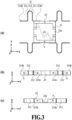
- FIG. 3 (a) is a top view of the vibration body 2 shown in FIG. 2 .
- FIG. 3 (b) is a side view of the vibration body 2 viewed in the y direction and
- FIG. 3 (c) is a side view of the vibration body 2 viewed in the x direction.
- the vibration body 2 is connected to the vibration energy harvesting element 1, vibrated by vibration of the vibration source at least in a plane direction, and configured to transfer vibration to the vibration energy harvesting element 1.
- the vibration body 2 comprises a fixing plate 24 that is a fixing portion to fix the vibration energy harvesting element 1 and four leaf springs 21 that are elastic bodies to transfer vibration from the vibration source to the fixing plate 24.
- the vibration body 2 of the present embodiment also comprises a frame body 23 to connect the leaf springs 21 to the fixing plate 24. That is, the frame body 23 is provided along the periphery of the fixing plate 24.
- the four leaf springs 21 are attached at intervals to each other along both ends of two opposing sides of the frame body 23. With such a configuration, each of the four leaf springs 21 can be independently vibrated.
- the frame body 23 also comprises notches 23a on a pair of opposing sides of the four sides as shown in FIG. 2 , FIG. 3 (a), and FIG. 3 (c) .
- the two pairs of leaf springs 21 provided with the notches 23a interposed therebetween can be vibrated without being affected by vibration of the opposing leaf springs 21 across the notches 23a.
- the present embodiment can easily adjust a mass of the vibration body 2 by providing the notches 23a of arbitrary size.
- the leaf spring 21 has one end connected to the fixing plate 24 via the frame body 23 and the other end connected to the vibration source via the support body 32 and the vibration transfer portion 34. Further, the leaf spring 21 is a so-called return spring in which a direction from one end 214a to the other end 214b is changed between the one end 214a and the other end 214b. That is, as is clear from FIG. 3 (a) or the like, an extending direction of the leaf spring 21 is oriented outside the fixing plate 24 from the one end 214a, reversed, and further changed to be oriented toward the end 214b.
- a portion extending outward is referred to as a first extending portion 211
- a portion in which the extending direction is reversed is referred to as a second extending portion 212
- a portion which is between the first extending portion 211 and the second extending portion 212 and in which the extending direction is changed is referred to as a curved portion 213.
- the vibration body 2 is formed of, for example, stainless steel, nickel alloy and titanium alloy, or a mixture or combination thereof.
- the vibration body 2, the attaching body 3, and the vibration energy harvesting element 1 are connected to one another by screwing and each have a plurality of holes h for screwing.
- the leaf spring 21 that is a return spring is bent such that the first extending portion 211 and the second extending portion 212 become close to or away from each other and the fixing plate 24 is vibrated in the ⁇ x directions.
- the leaf spring 21 has a constant width and thickness and is therefore stiffer than a coil spring or the like and less prone to being displaced in the y direction.
- the leaf spring 21 resists twisting even if a moment having its center at the end 214a is applied, and the fixing plate 24 is vibrated on a virtual plane approximately only in the x direction.
- the virtual plane here is a plane parallel to the top surface of the attaching portion 31.
- each of the four leaf springs 21 overlaps the side surface of the fixing plate 24 such that the fixing plate 24 can be stably held from the four directions.
- the vibration energy harvesting element 1 is arranged such that its center of gravity is located within a range of the fixing plate 24 overlapping an area supported by the leaf springs 21. Such a configuration eliminates the occurrence of an unexpected moment or the like in a design of the vibration energy harvesting unit to be described later and helps to form a vibration energy harvesting unit having a function as designed.
- the vibration energy harvesting element 1 comprises a package 11 which seals a energy harvesting portion 4 ( FIG. 4 ) that is a mechanism for energy harvest, a stage 13 which fixes the package 11, and a connector 12 which takes out energy harvested by the energy harvesting portion 4.
- a surface of the stage 13 facing the fixing plate 24 is larger in area than a surface facing the energy harvesting portion 4. It is preferable that the shape of the stage 13 be substantially identical to and slightly smaller in area than the fixing plate 24. According to this configuration, after the energy harvesting portion 4 sealed by the package 11 is fixed to the stage 13, the energy harvesting portion 4 can be screwed onto the frame body 23 with unshown screws and easily aligned with the vibration body 2.
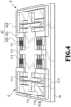
- FIG. 4 is a perspective view of the energy harvesting portion 4 of the vibration energy harvesting element 1.
- FIG. 5 is a top view of the energy harvesting portion 4 shown in FIG. 4 to show a state of vibration of the energy harvesting portion 4.
- the energy harvesting portion 4 of the vibration energy harvesting element 1 comprises a base portion 40 and a movable electrode 41 and two fixed electrodes 42 fixed to the base portion 40.
- the movable electrode 41 comprises a plurality of movable electrode portions 415, a base shaft 411 of the plurality of movable electrode portions 415, a plate body 412 crossing the base shaft 411, a spring 413 provided on both sides of the plate body 412, and a fixing portion 414 fixing the movable electrode 41 to the base portion 40.
- the plurality of movable electrode portions 415 of the present embodiment are arranged in a direction (y direction) crossing the extending direction (x direction in FIG. 5 ) to form a comb electrode.
- a group of the movable electrode portions 415 is also herein referred to as "movable comb electrode.”
- Such a energy harvesting portion 4 is formed by processing a silicon on insulator (SOI) substrate including silicon and silicon oxide.
- the spring 413 includes two spring portions 413a, 413b, 413c, and 413d parallel to the base shaft 411.
- the spring portions 413a and 413b are arranged to face each other at an interval and both ends of the spring portions 413a and 413b are connected by the spring portions 413c and 413d, respectively.
- a single fixed electrode 42 is provided on each of the two sides of the movable electrode 41.
- the two fixed electrodes 42 are arranged axisymmetrically to each other and comprise a plurality of fixed electrode portions 425, a base shaft 421 of the plurality of fixed electrode portions 425, and a fixing portion 424 which fixes the fixed electrode 42 to the base portion 40.
- the plurality of fixed electrode portions 425 are arranged in a direction (y direction) crossing the extending direction (x direction in FIG. 5 ) to form a comb electrode.
- a group of the fixed electrode portions 425 is also herein referred to as "fixed comb electrode.”
- the fixing portion 424 has a substantially frame-like shape connected to both ends of the base shaft 421 and supports both ends of the base shaft 421.
- the vibration energy harvesting element 4 is arranged such that the movable comb electrode and the fixed comb electrode partially overlap in the extending direction and face each other.
- Such a energy harvesting portion 4 of the vibration energy harvesting element 1 comprises the fixed electrode portions 425 extending in one direction and the movable electrode portions 415 facing the fixed electrode portions 425 and vibrated in one plane, and harvests energy by relative vibration of the fixed electrode portions 425 and the movable electrode portions 415.
- the spring portion 413a and spring portion 413b of the spring 413 are bent in the -x and +x directions while being separated from each other by the spring portion 413c and spring portion 413d, and the plate body 412 and base shaft 411 connecting with the spring 413 are vibrated in the -x and +x directions.
- the plurality of movable electrode portions 415 are vibrated in the -x and +x directions.
- the fixing portion 424 is fixed to the base portion 40 and the fixed comb electrode continued to the fixing portion 424 is also fixed.
- the movable comb electrode and the fixed comb electrode are vibrated relatively in the x direction while facing each other.
- the two springs 413 are both fixed to the base portion 40 by the fixing portion 414 and supported by the base shaft 411 and plate body 412 there between. Accordingly, they are vibrated on a plane parallel to the x axis without receiving a force in a rotational direction about the x axis.
- the vibration energy harvesting element 1 may have any configuration as long as the fixed comb electrode and the movable comb electrode are vibrated on a plane and is not limited to the configuration in which the movable electrode portions 415 are vibrated in their extending direction.
- the movable electrode portions 415 may be vibrated between the fixed comb electrodes in a longitudinal direction of the base shaft 411, namely a direction orthogonal to the extending direction.
- At least one of the fixed electrode portion 425 and the movable electrode portion 415 is electretized.
- an electret indicates a substance holding a permanent electric charge and "electretized" means that an electret layer is formed on a surface of at least one of the movable electrode portion 415 and the fixed electrode portion 425.
- FIG. 6 (a) and FIG. 6 (b) are schematic views of the movable electrode portion 415 and the fixed electrode portion 425 to illustrate an electret.
- surfaces of portions of the fixed electrode portion 425 and the movable electrode portion 415 facing each other comprise oxide films 425a and 415a made of SiO 2 (silicon dioxide), respectively, and only the oxide film on the fixed electrode portion 425 side is an electret layer fixing a negative charge.
- the fixing of the negative charge can be realized by, for example, bias-temperature treatment (B-T treatment) which moves an ion doped in an oxide film at a high temperature, as stated in Japanese Patent Laid-Open No. 2014-049557 .
- B-T treatment bias-temperature treatment
- the oxide film 425a to which the negative charge is fixed is formed on the surface of the fixed electrode portion 425.
- a positive charge in silicon (silicon) induced by the negative charge fixed to the oxide film 425a is moved as an inductive charge. Arrows in the drawing show electric flux lines.
- the negative charge in the oxide film 425a does not move at room temperature and stays near the boundary between the silicon and the oxide film in the oxide film 425a, but a distance between the negative charge and the boundary is sufficiently smaller than the oxide film thickness.
- a charge density of the oxide film 425a is ⁇ 1
- the charge density ⁇ 1 and a potential difference V1 between the movable electrode portion 415 and the fixed electrode portion 425 produce an inductive charge of a charge density ⁇ 2 at an interface of the movable electrode portion 415. Due to a neutral condition of the charge, an inductive charge of a charge density - ⁇ 1 - ⁇ 2 is induced in the fixed electrode portion 425.
- energy harvesting portion 4 energy is harvested by taking out the inductive charge.
- FIG. 6 (b) is a diagram showing a model for obtaining a formula for calculating a charged voltage V 0 produced between the fixed electrode portion 425 and the movable electrode portion 415 shown in FIG. 6 (a) .
- the model shown in FIG. 6 (b) includes the fixed electrode portion 425, the oxide film 425a, and the movable electrode portion 415.
- g1 is a distance between the negative charge fixed in the oxide film 425a and the inductive charge induced in the fixed electrode portion 425.
- a distance g2 is a distance between the fixed negative charge and the inductive charge induced in the movable electrode portion 415.
- V 0 ⁇ g 1 ⁇ ⁇ 1 / ⁇ 0
- the permittivity of the oxide films 425a and 415a is ignored.
- the amount of energy harvest taken out in the energy harvesting portion 4 increases with an increase in the charged voltage V 0 .
- the vibration energy harvesting unit 100 having the configuration explained above, since the movable comb electrode and the fixed comb electrode are vibrated on a plane, there is no need to secure a space in a direction crossing the plane and a vibration energy harvesting unit advantageous for thickness reduction can be realized.
- the vibration energy harvesting unit 100 moving on the horizontal plane interference of the attaching body 3 and the vibration body 2 with each other is small and a mechanical stiffness of the attaching body 3 in the vibrating direction can be increased as compared with a configuration of vibration in the vertical direction.
- FIG. 7 is a graph showing a result of calculating an amplitude while changing a mass ratio (m 1 /m 2 ) between the vibration energy harvesting element 1 and the vibration body 2 in the vibration energy harvesting unit 100 explained above.
- the vertical axis indicates the amplitude of the vibration energy harvesting unit 100 and the horizontal axis indicates a frequency corresponding to the amplitude.
- Characteristics c1 to c5 shown in FIG. 7 are of a dual-mass vibration system in which the mass ratio increases in the order of the characteristics c1, c2, c3, c4, and c5, that is, a mass m 2 of the vibration body 2 is smaller than a mass m 1 of the vibration energy harvesting element 1. It can be understood from FIG.
- the amount of energy harvest proportional to the amplitude of the vibration energy harvesting unit 100 of the present embodiment has a first frequency smaller than the energy harvest natural frequency and a second frequency larger than the energy harvest natural frequency, has a first peak at the first frequency, has a second peak at the second frequency, and has a convex downward inflection point between the first frequency and the second frequency.
- a range of frequency in which the first peak and the second peak appear (hereinafter also referred to as "peak interval") is changed by adjusting the mass ratio between the vibration energy harvesting element 1 and the vibration body 2 and this change occurs such that the range becomes wider with an increase in the mass ratio between the vibration energy harvesting element 1 and the vibration body 2 and becomes narrower with a decrease in the mass ratio.
- the first peak and the second peak become smaller with an increase in the mass ratio between the vibration energy harvesting element 1 and the vibration body 2 and become larger with a decrease in the mass ratio.
- the present embodiment uses such a phenomenon to obtain a method and program for designing a vibration energy harvesting unit capable of accurately obtaining the peak interval between the first peak and the second peak and the smallest amount of energy harvest (amplitude) within this range. Further, a vibration energy harvesting unit capable of stably obtaining a desired amount of energy harvest in a desired frequency band is configured.
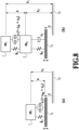
- FIG. 8 (a) and FIG. 8 (b) are diagrams showing models of vibration systems used in the method for designing the vibration energy harvesting unit of the present embodiment.
- FIG. 8 (a) shows a single-mass vibration system in a case where the vibration energy harvesting element 1 is vibrated without being attached to the vibration body 2
- FIG. 8 (b) shows a dual-mass vibration system formed by the vibration energy harvesting element 1 and the vibration body 2.
- the present embodiment normalizes the dual-mass vibration system of FIG.
- a position reference surface to be an origin of position is shown as 70 and a vibration reference surface to be a reference of vibration is shown as 71.
- m 1 is a mass of the vibration energy harvesting element 1
- m 2 is a mass of the vibration body 2
- k 1 is a spring constant of vibration of the vibration energy harvesting element 1
- k 2 is a spring constant of vibration of the vibration body 2
- c 1 is a comprehensive attenuation coefficient of the vibration energy harvesting element 1 and is expressed by the sum of a mechanical attenuation coefficient c m and an electrical attenuation coefficient c e .
- c 2 is a mechanical attenuation coefficient of the vibration body 2.
- the mass m 1 is an overall mass of the vibration energy harvesting element 1 including the package 11 and the stage 13.
- the mass m 2 is an overall mass obtained by excluding the vibration energy harvesting element 1 from the vibration energy harvesting unit 100.
- FIG. 9 is a schematic view for illustrating this point.
- a portion obtained by excluding the mass of the movable electrode 41 exclusive of the fixing portion 414 from the mass of the vibration energy harvesting element 1 is defined as a weight 2a
- a portion of the vibration body 2 fixing the weight 2a is defined as "frame”
- a mass thereof mainly a portion of the fixing plate 24
- the mass of the vibration body is m 2
- the mass of the weight 2a is mf
- the mass of the weight 2b (mainly the portion of the fixing plate 24) is m' 2
- the shape of the fixing plate 24 is designed such that the center of mass of the vibration body 2 falls within the area supported by the four leaf springs 21, more preferably such that the center of mass of the vibration energy harvesting element 1 matches a geometrical center of the vibration body 2.
- this point is based on the premise that the vibration body 2 has a structure symmetrical with respect to a plane passing through its geometrical center. The widening of the band and an increase rate of the amount of energy harvest in the design of the vibration energy harvesting unit 100 of the dual-mass vibration system of an embodiment of the present invention will be described below by the use of the models of the vibration systems of FIG. 8 (a), FIG. 8 (b) , and FIG. 9 .
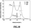
- FIG. 10 is a diagram for illustrating a method for designing a vibration energy harvesting unit of the present embodiment.
- ⁇ is a frequency (frequency)
- Q is a natural frequency of a target vibration system.
- ⁇ 2p indicates a range of frequency (hereinafter also referred to as "peak interval") between the two peaks (the first peak and the second peak) of the amount of energy harvest, and the characteristic of the normalized amount of energy harvest has a convex downward inflection point between the peaks. That is, the vibration energy harvesting unit 100 of the present embodiment can realize a large amount of energy harvest in a wide range of frequency and the peak interval ⁇ 2p shows an index of the widening of the band.
- This peak interval ⁇ 2p can be obtained as follows.
- p 1DOF and p 2DOF to be normalized amounts of energy harvest of the vibration energy harvesting element 1 and the vibration energy harvesting unit of the present embodiment are expressed by Formula (1a) and Formula (1b) below.
- p 2DOF 4 ⁇ 1 2 ⁇ 2 ⁇ 6 ⁇ 2 + 4 ⁇ 2 2 ⁇ 2 ⁇ 2 ⁇ A ⁇ 2 + ⁇ 2 + ⁇ B ⁇ 3 + C ⁇ 2 Formula 1 a
- p 1DOF 4 ⁇ 1 2 ⁇ 6 ⁇ 2 ⁇ 1 2 + 2 ⁇ 1 ⁇ 2 Formula 1 b
- each of A, B, and C is as follows.
- A 1 + ⁇ 2 + ⁇ + 4 ⁇ 1 ⁇ 2 ⁇
- B 2 ⁇ 1 1 + ⁇ + ⁇ 2 ⁇
- C 2 ⁇ 1 + ⁇ 2 ⁇
- ⁇ 1 is an attenuation coefficient of the vibration energy harvesting element 1 in the case of the single-mass vibration system not connected to the vibration body 2
- ⁇ 2 is an attenuation coefficient of the vibration body 2 in the case of the single-mass vibration system not connected to the vibration energy harvesting element 1.
- ⁇ p 2 DOF / p 1DOF
- a in Formula (4) is given by Formula (5).
- ⁇ 4 ⁇ 1 ⁇ ⁇ 2 ⁇ ⁇ 1 + 4 ⁇ 1 2
- Formula 4 ⁇ ⁇ 2 2 ⁇ 1 + 4 ⁇ 1 2 ⁇ 2 2 1 ⁇ 1 ⁇ ⁇ 1 4 ⁇
- Formula 5
- ⁇ 2 ⁇ ⁇ 1 1 + 2 ⁇ 1 ⁇ 1 ⁇ 2 ⁇ 1 ⁇ 1 2 ⁇ 1
- F1 and F 2 are expressed by Formula (10) below.
- ⁇ 2 and ⁇ 4 are frequencies corresponding to the peaks of the first peak and the second peak shown in FIG. 10 .
- ⁇ 1 ⁇ 1 F 1 is 4 and F 2 is 2 2 ⁇ 1 / ⁇
- ⁇ 2p is expressed by Formula (11) below.
- [Math. 6] ⁇ ⁇ 2 p 2 ⁇ ⁇ 1
- the peak interval ⁇ 2p explained above is an index of the widening of the band, and as this value increases, a large amount of energy harvest can be realized in a wider range of frequency.
- the energy harvest amount increase rate ⁇ indicates a minimum value of the amount of energy harvest realized within the range of the peak interval ⁇ 2p , and as this value increases, a larger amount of energy harvest can be realized in the widened range of frequency.
- the vibration energy harvesting unit of the present embodiment can obtain a relatively large amount of energy harvest (e.g., 500 ⁇ W) from a vibration source having a frequency of 3000 Hz or less and an acceleration of 1G or less.
- the vibration energy harvesting unit of the present embodiment realizes a vibration system having a relatively high quality factor (hereinafter also referred to as Q value) and realizes it as one having the above-described peak interval ⁇ 2p and increase rate ⁇ defined within the range of this high Q value.
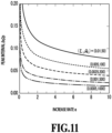
- FIG. 11 is a diagram in which the relationship of Formula (11) is expressed by using the attenuation ratio ⁇ 1 and Q value of the vibration energy harvesting element 1 as parameters.
- the Q value increases, that is, as the attenuation ratio ⁇ 1 decreases, the peak interval ⁇ 2p decreases for the same increase rate ⁇ .
- a peak interval ⁇ 2p and increase rate ⁇ adapted to an environment for using the vibration energy harvesting unit of the present embodiment can be determined. Further, the structure of the vibration energy harvesting unit is determined such that it has a quality factor Q 1 corresponding to the determined peak interval ⁇ 2p and increase rate ⁇ . For example, if the structure of the energy harvesting vibration body is determined such that it has an attenuation ratio ⁇ 1 corresponding to a quality factor Q 1 as shown by the five pairs shown in FIG.
- the inventors of the present invention obtained a value not less than 0.0001 and not more than 0.008 as the range of the mass ratio m 1 /m 2 when a minimum value of the energy harvest increase rate ⁇ was 1.5, a maximum value thereof was 100, a minimum value of the attenuation ratio of the vibration energy harvesting element 1 was 0.0005, and a maximum value thereof was 0.01.
- the energy harvesting unit of the present embodiment is not limited to such an attenuation ratio, energy harvest increase rate, and mass ratio.
- An attenuation ratio, energy harvest increase rate, and mass ratio suitable for the vibration energy harvesting unit 100 differ according to use of the vibration energy harvesting unit, an environment to which the vibration energy harvesting unit is applied, a vibration source, further a range of frequency of vibration of the vibration source, and the like.
- the energy harvest natural frequency ⁇ 1 and the vibration natural frequency ⁇ 2 may be identical to or different from each other.
- the characteristic of the minimum amount of energy harvest in the peak interval of the vibration energy harvesting unit that is, the amount of energy harvest at the convex downward inflection point between the peaks changes with an increase in difference between the vibration natural frequency and energy harvest natural frequency ⁇ 1 and ⁇ 2 .
- FIG. 12 is a graph for illustrating this point.
- the horizontal axis indicates a normalized frequency of the dual-mass vibration system model shown in FIG. 8 (b) normalized by the single-mass vibration system model shown in FIG.
- the vertical axis indicates a normalized amount of energy harvest corresponding to the normalized frequency.
- the characteristic c11 is of a single-mass vibration system of only the vibration energy harvesting element 1 and c8 is of a dual-mass vibration system in which the energy harvest natural frequency is substantially identical to the vibration natural frequency.
- a ratio between the energy harvest natural frequency ⁇ 1 and the vibration natural frequency ⁇ 2 is referred to as a frequency ratio ⁇ 1 / ⁇ 2
- the frequency ratio ⁇ 1 / ⁇ 2 is expressed by Formula (13).
- [Math. 8] ⁇ 1 ⁇ 2 1 1 + ⁇ 2 ⁇ 1 4 ⁇
- the characteristic c6 is one in a case where the frequency ratio between the vibration energy harvesting element 1 and the vibration body 2 is smaller than 1/(1+ ⁇ / ⁇ 2) by ⁇ /2.
- the characteristic c7 is one in a case where the frequency ratio is smaller than 1/(1+ ⁇ / ⁇ 2) by ⁇ /4.
- the characteristic c9 is one in a case where the frequency ratio is larger than 1/(1+ ⁇ / ⁇ 2)by ⁇ /4.
- the characteristic c10 is one in a case where the frequency ratio is larger than 1/(1+ ⁇ / ⁇ 2) by ⁇ /2.
- the inventors of the present invention focused attention on the fact that as shown in FIG. 12 , a difference between the frequency ratio and 1/(1+ ⁇ / ⁇ 2) shifts frequencies at which peaks appear and the shift changes an amount of energy harvest and a frequency at which the amount of energy harvest takes a minimum value.
- a decrease in harvested energy caused by a shift of the frequency ratio is allowed up to 15% and the frequency ratio falling within the range of Formula (13) above is treated as one of design conditions.
- the method for designing the vibration energy harvesting unit of the present embodiment can obtain a mass ratio corresponding to a desired energy harvest increase rate or peak interval by the use of Formula (6), Formula (8), and Formula (12). Further, in contrast, the present embodiment can first determine a mass ratio between the vibration energy harvesting element 1 and the vibration body 2 of the vibration energy harvesting unit and predict a energy harvest increase rate and a peak interval of the vibration energy harvesting unit formed by these vibration element 1 and vibration body 2.
- an input of at least one of mass information about at least one of the mass of the vibration energy harvesting element 1 and the mass of the vibration body 2, frequency information about a frequency range including the first peak and the second peak of the vibration energy harvesting unit, and energy harvest information about an amount of energy harvest harvested by the vibration energy harvesting unit in the frequency range can be received, and at least one of the mass information, the frequency information, and the energy harvest information that has not been input can be output based on the information whose input has been accepted out of the above information.
- the present embodiment can design the vibration energy harvesting unit described above by means of a computer and construct a program for designing the vibration energy harvesting unit for executing the above method.
- a program includes a function of receiving an input of at least one of the mass information, frequency information, and energy harvest information stated above, a function of calculating information that has not been input based on the input information, and a function of outputting the result of calculation.
- the function of receiving an input is formed by, for example, a user interface such as a keyboard or voice input device, display screen, or touch pen, and a central processing unit (CPU) or graphics processing unit (GPU) which controls the hardware.
- CPU central processing unit
- GPU graphics processing unit
- the function of calculating information is formed by a CPU which executes arithmetic processing, a storage unit which temporarily or non-temporarily stores data used for processing and input data, a working memory used for arithmetic operations, and the like.
- the function of outputting is formed by, for example, a voice input device, display screen, printer, and CPU or GPU controlling them.
- such a program for designing the vibration energy harvesting unit may input or output the peak interval shown in, for example, FIG. 10 or FIG. 11 , as the frequency information.
- the peak interval is expressed by a range of frequency between peaks that the dual-mass vibration system shown by the model of FIG. 8 (b) has at the respective two frequencies.
- the program for designing the vibration energy harvesting unit may input or output the band widening gain ⁇ shown in Formula (8) as the frequency information.
- the program for designing the vibration energy harvesting unit may input or output the energy harvest amount increase rate ⁇ shown in Formula (6) as the energy harvest information.
Landscapes
- Engineering & Computer Science (AREA)
- Power Engineering (AREA)
- General Electrical Machinery Utilizing Piezoelectricity, Electrostriction Or Magnetostriction (AREA)
- Apparatuses For Generation Of Mechanical Vibrations (AREA)
- Jigging Conveyors (AREA)
Abstract
Description
- The present invention relates to a vibration energy harvesting unit, a method for designing a vibration energy harvesting unit, and a program for designing a vibration energy harvesting unit, and more specifically, relates to a vibration energy harvesting technique in a dual-mass vibration system.
- A vibration energy harvesting element which harvest energy by vibration is used in various situations as a energy source that can be arranged in a site difficult to perform maintenance frequently, as it does not require battery replacement or wire routing. The amount of energy harvest by the vibration energy harvesting element has its peak with a natural frequency at which the vibration energy harvesting element vibrates largely, and decreases as the frequency becomes away from its peak. As the peak of the amount of energy harvest becomes steeper, the frequency band in which a sufficient amount of energy harvest is obtained becomes narrower, a shift in frequency largely affects the amount of energy harvest, and the operation of the vibration energy harvesting element becomes unstable. Accordingly, in order to stabilize energy harvesting by the vibration energy harvesting element, it is preferable that a frequency band in which a necessary amount of energy harvest is obtained be wide.
- From the above point, there is currently a configuration of a dual-mass vibration system in which a vibration energy harvesting element is attached to a member having a different mass and the vibration energy harvesting element is vibrated together with this member. Such a configuration is described in, for example,
PTL 1. In a vibration energy harvester disclosed inPTL 1, a vibration energy harvesting unit is attached to a pedestal to form a dual-mass vibration system including a point mass including the pedestal and a weight and coil spring attached to the pedestal and a point mass including a weight and coil spring of the energy harvesting unit attached onto the pedestal.PTL 1 states that the amount of energy harvest by the vibration energy harvester of the dual-mass vibration system has two peaks on both sides of the natural frequency of the weight and coil spring of the energy harvesting unit and that the frequencies at which these peaks appear increase and decrease according to a mass ratio between the weight of the pedestal and the weight of the energy harvesting unit. -
PTL 1 also states that the amount of energy harvest by the energy harvesting unit is increased by increasing the amplitude of a magnet or coil. - PTL 1:
Japanese Patent Laid-Open No. 2011-172351 - However, in the configuration disclosed in
PTL 1, the weight attached to the pedestal is vibrated by a coil spring provided between the pedestal and a slab. With such a configuration, the features such as the weight and the pedestal upsize the entire vibration energy harvester and limits are impose on a place to install the energy harvester. In addition, the weight vibrates in a direction orthogonal to the pedestal. If the amount of energy harvest is secured by increasing the amplitude of this vibration, there is a need to secure a space to vibrate the weight and it is difficult to reduce the thickness of the vibration energy harvester. An increase in thickness of the vibration energy harvester is disadvantageous for attaching the energy harvester to an indoor duct or wall. -
PTL 1 also states that the two peaks of the amount of energy harvest can increase the vibration amplification rate in a frequency band around the natural frequency of the weight and coil spring of the vibration energy unit and stabilize energy harvest. However,PTL 1 only discloses a relationship between the widening of a frequency band to realize a large amount of energy harvest and the vibration amplification rate, and a desired amount of energy harvest cannot be obtained in relation to the widening of the band or the like in suitable correspondence with a specific vibration source. - The present invention aims to provide a vibration energy harvesting unit advantageous for thickness reduction and clear as to a frequency bandwidth in which desired harvested energy is obtained, a method for designing such a vibration energy harvesting unit, and a program for designing a vibration energy harvesting unit. The present invention also aims to provide a vibration energy harvesting unit capable of obtaining a desired amount of energy harvest in correspondence with a specific vibration source, a method for designing such a vibration energy harvesting unit, and a program for designing a vibration energy harvesting unit.
- To solve the above problem, a vibration energy harvesting unit of an aspect of the present invention comprises: a vibration energy harvesting body comprising a fixed electrode portion extending in one direction and a movable electrode portion facing the fixed electrode portion and vibrated in one plane, the vibration energy harvesting body harvesting energy by relative vibration of the fixed electrode portion and the movable electrode portion; and a vibration body connected to the vibration energy harvesting body, vibrated by vibration of a vibration source at least in the plane direction, and transferring vibration to the vibration energy harvesting body.
- A method for designing a vibration energy harvesting unit of an aspect of the present invention is a method for designing a vibration energy harvesting unit for designing a vibration energy harvesting unit comprising: a vibration energy harvesting body comprising a fixed electrode portion extending in one direction and a movable electrode portion facing the fixed electrode portion and vibrated in one plane, the vibration energy harvesting body harvesting energy by relative vibration of the fixed electrode portion and the movable electrode portion; and a vibration body connected to the vibration energy harvesting body, vibrated by vibration of a vibration source at least in the plane direction, and transferring vibration to the vibration energy harvesting body, the method comprising: an information input receiving step of receiving an input of at least one of mass information about at least one of a mass of the vibration energy harvesting body and a mass of the vibration body, frequency information about a frequency range in which the vibration energy harvesting unit has a peak of an amount of energy harvest, and energy harvest information about an amount of energy harvest harvested by the vibration energy harvesting unit in the frequency range; and an information outputting step of outputting at least one of the mass information, the frequency information, and the energy harvest information that has not been input in the information input receiving step based on information whose input has been received by the information input receiving function out of the mass information, the frequency information, and the energy harvest information.
- A program for designing a vibration energy harvesting unit of an aspect of the present invention is a program for designing a vibration energy harvesting unit for designing a vibration energy harvesting unit comprising: a vibration energy harvesting body comprising a fixed electrode portion extending in one direction and a movable electrode portion facing the fixed electrode portion and vibrated in one plane, the vibration energy harvesting body harvesting energy by relative vibration of the fixed electrode portion and the movable electrode portion; and a vibration body connected to the vibration energy harvesting body, vibrated by vibration of a vibration source at least in the plane direction, and transferring vibration to the vibration energy harvesting body, the program comprising: a function of receiving an input of at least one of mass information about at least one of a mass of the vibration energy harvesting body and a mass of the vibration body, frequency information about a frequency range in which the vibration energy harvesting unit has a peak of an amount of energy harvest, and energy harvest information about an amount of energy harvest harvested by the vibration energy harvesting unit in the frequency range; and a function of outputting at least one of the mass information, the frequency information, and the energy harvest information that has not been input based on information whose input has been received by the function of receiving the input out of the mass information, the frequency information, and the energy harvest information.
- According to the above aspects, a vibration energy harvesting unit advantageous for thickness reduction and clear as to a frequency bandwidth in which desired harvested energy is obtained, a method for designing such a vibration energy harvesting unit, and a program for designing a vibration energy harvesting unit can be provided. In addition, a vibration energy harvesting unit capable of obtaining a desired amount of energy harvest in correspondence with a specific vibration source, a method for designing such a vibration energy harvesting unit, and a program for designing a vibration energy harvesting unit can be provided.
-
- [
FIG. 1 ] A perspective view for illustrating a vibration energy harvesting unit of an embodiment of the present invention. - [
FIG. 2 ] An exploded perspective view of the vibration energy harvesting unit shown inFIG. 1 . - [
FIG. 3 ] (a) is a top view of avibration body 2 shown inFIG. 2 and(b) and (c) are side views thereof. - [
FIG. 4 ] A perspective view of a energy harvesting portion of a vibration energy harvesting element shown inFIG. 2 . - [
FIG. 5 ] A top view of the energy harvesting portion shown inFIG. 4 to show a state of vibration of the energy harvesting portion. - [
FIG. 6 ] (a) and (b) are schematic views of a movable electrode portion and a fixed electrode portion to illustrate an electret. - [
FIG. 7 ] A graph showing a result of calculating an amplitude while changing a mass ratio between the vibration energy harvesting element and vibration body of the vibration energy harvesting unit shown inFIG. 1 . - [
FIG. 8 ] (a) is a diagram showing a single-mass vibration system model and (b) is a diagram showing a dual-mass vibration system model. - [
FIG. 9 ] A diagram for illustrating an imbalance of mass in a vibration model shown inFIG. 8 (b) . - [
FIG. 10 ] A diagram for illustrating a method for designing a vibration energy harvesting unit of an embodiment of the present invention. - [
FIG. 11 ] A graph showing a relationship among a peak interval, an attenuation ratio ζ1 of a vibration energy harvesting element, and a Q value in an embodiment of the present invention. - [
FIG. 12 ] A graph for illustrating a relationship between an amount of shift in natural frequency of each of a vibration energy harvesting element and a vibration body and an amount of energy harvest. - A vibration energy harvesting unit of an embodiment of the present invention will be described below with reference to the drawings. The drawings show examples of a technical idea, constituent members, their arrangements and relationships with each other, actions, and functions of the present embodiment and do not limit specific configurations or shapes thereof.
-
FIG. 1 is a perspective view for illustrating a vibrationenergy harvesting unit 100 of the present embodiment.FIG. 2 is an exploded perspective view of the vibrationenergy harvesting unit 100 shown inFIG. 1 . The vibrationenergy harvesting unit 100 comprises a vibration energy harvesting body and avibration body 2 connected to the vibration energy harvesting body and vibrated by vibration of a vibration source together with the vibration energy harvesting body. Thevibration body 2 is attached to an attachingbody 3 and attached to a desired attaching surface such as a wall, floor, or duct. The vibration energy harvesting body of the present embodiment is a vibrationenergy harvesting element 1 which harvest energy by means of electrodes and includes a circuit or the like which takes out the harvested energy. In the description of the present embodiment, a coordinate system shown inFIG. 1 andFIG. 2 is used to specify a positional relationship in the vibrationenergy harvesting unit 100. That is, the description of the present embodiment defines a longitudinal direction of the vibrationenergy harvesting unit 100 as an x direction, a direction orthogonal to the x axis as a y direction, and a direction orthogonal to the x axis and the y axis as a z direction. In the present embodiment, a length in the z direction is also referred to as "width," a side with a large numerical value of the z axis is treated as "above" a side with a small numerical value, and the small side is treated as "below" the large side. Such an up and down relationship along the z axis does not obey gravity and the vibrationenergy harvesting unit 100 may be attached such that the vibrationenergy harvesting element 1 is oriented either upward or downward. Each of the features forming the vibrationenergy harvesting unit 100, that is, the attachingbody 3, thevibration body 2, and the vibrationenergy harvesting element 1, will be described below. - As shown in
FIG. 2 , the attachingbody 3 comprises an attachingportion 31, twosupport bodies 32 provided at an interval to each other on the top surface of the attachingportion 31, and avibration transfer portion 34 formed to contact at least one of thesupport bodies 32. The attachingportion 31 is a surface on which thesupport bodies 32 are placed without being fixed with an adhesive or the like. Thevibration transfer portion 34 has a hole H to connect with an unshown vibration source and a member vibrated by vibration of the vibration source is inserted into the hole H. The vibration source may use, for example, vibration of a motor or the like of a facility, vibration produced by travel of a vehicle or train, or vibration produced when a person walks. - As shown in
FIG. 2 , thesupport body 32 on thevibration transfer portion 34 side is attached from thevibration transfer portion 34 to the attachingportion 31, while theother support body 32 is attached to the attachingportion 31. With such a configuration, thesupport body 32 is vibrated directly by thevibration transfer portion 34. As will be described later, thevibration body 2 is attached to thesupport bodies 32 and the vibrationenergy harvesting element 1 contacts thevibration body 2. Thesupport bodies 32 can directly contact thevibration transfer portion 34 and thevibration body 2 and efficiently transfer vibration applied to thevibration transfer portion 34 to thevibration body 2 and the vibrationenergy harvesting element 1. -
FIG. 3 (a) is a top view of thevibration body 2 shown inFIG. 2 .FIG. 3 (b) is a side view of thevibration body 2 viewed in the y direction andFIG. 3 (c) is a side view of thevibration body 2 viewed in the x direction. Thevibration body 2 is connected to the vibrationenergy harvesting element 1, vibrated by vibration of the vibration source at least in a plane direction, and configured to transfer vibration to the vibrationenergy harvesting element 1. As is clear fromFIG. 1 andFIG. 2 , thevibration body 2 comprises a fixingplate 24 that is a fixing portion to fix the vibrationenergy harvesting element 1 and fourleaf springs 21 that are elastic bodies to transfer vibration from the vibration source to the fixingplate 24. Thevibration body 2 of the present embodiment also comprises aframe body 23 to connect theleaf springs 21 to the fixingplate 24. That is, theframe body 23 is provided along the periphery of the fixingplate 24. The fourleaf springs 21 are attached at intervals to each other along both ends of two opposing sides of theframe body 23. With such a configuration, each of the fourleaf springs 21 can be independently vibrated. - The
frame body 23 also comprisesnotches 23a on a pair of opposing sides of the four sides as shown inFIG. 2 ,FIG. 3 (a), and FIG. 3 (c) . With such a configuration, the two pairs ofleaf springs 21 provided with thenotches 23a interposed therebetween can be vibrated without being affected by vibration of the opposingleaf springs 21 across thenotches 23a. Further, the present embodiment can easily adjust a mass of thevibration body 2 by providing thenotches 23a of arbitrary size. - As is clear from
FIG. 1 andFIG. 2 , theleaf spring 21 has one end connected to the fixingplate 24 via theframe body 23 and the other end connected to the vibration source via thesupport body 32 and thevibration transfer portion 34. Further, theleaf spring 21 is a so-called return spring in which a direction from oneend 214a to theother end 214b is changed between the oneend 214a and theother end 214b. That is, as is clear fromFIG. 3 (a) or the like, an extending direction of theleaf spring 21 is oriented outside the fixingplate 24 from the oneend 214a, reversed, and further changed to be oriented toward theend 214b. In the present embodiment, of theleaf spring 21, a portion extending outward is referred to as a first extendingportion 211, a portion in which the extending direction is reversed is referred to as a second extendingportion 212, and a portion which is between the first extendingportion 211 and the second extendingportion 212 and in which the extending direction is changed is referred to as acurved portion 213. - The
vibration body 2 is formed of, for example, stainless steel, nickel alloy and titanium alloy, or a mixture or combination thereof. Thevibration body 2, the attachingbody 3, and the vibrationenergy harvesting element 1 are connected to one another by screwing and each have a plurality of holes h for screwing. - The
leaf spring 21 that is a return spring is bent such that the first extendingportion 211 and the second extendingportion 212 become close to or away from each other and the fixingplate 24 is vibrated in the ±x directions. At this time, theleaf spring 21 has a constant width and thickness and is therefore stiffer than a coil spring or the like and less prone to being displaced in the y direction. Further, theleaf spring 21 resists twisting even if a moment having its center at theend 214a is applied, and the fixingplate 24 is vibrated on a virtual plane approximately only in the x direction. Incidentally, the virtual plane here is a plane parallel to the top surface of the attachingportion 31. - Further, the
entire end 214a of each of the fourleaf springs 21 overlaps the side surface of the fixingplate 24 such that the fixingplate 24 can be stably held from the four directions. The vibrationenergy harvesting element 1 is arranged such that its center of gravity is located within a range of the fixingplate 24 overlapping an area supported by the leaf springs 21. Such a configuration eliminates the occurrence of an unexpected moment or the like in a design of the vibration energy harvesting unit to be described later and helps to form a vibration energy harvesting unit having a function as designed. - As shown in
FIG. 1 andFIG. 2 , the vibrationenergy harvesting element 1 comprises apackage 11 which seals a energy harvesting portion 4 (FIG. 4 ) that is a mechanism for energy harvest, astage 13 which fixes thepackage 11, and aconnector 12 which takes out energy harvested by the energy harvesting portion 4. A surface of thestage 13 facing the fixingplate 24 is larger in area than a surface facing the energy harvesting portion 4. It is preferable that the shape of thestage 13 be substantially identical to and slightly smaller in area than the fixingplate 24. According to this configuration, after the energy harvesting portion 4 sealed by thepackage 11 is fixed to thestage 13, the energy harvesting portion 4 can be screwed onto theframe body 23 with unshown screws and easily aligned with thevibration body 2. -
FIG. 4 is a perspective view of the energy harvesting portion 4 of the vibrationenergy harvesting element 1.FIG. 5 is a top view of the energy harvesting portion 4 shown inFIG. 4 to show a state of vibration of the energy harvesting portion 4. The energy harvesting portion 4 of the vibrationenergy harvesting element 1 comprises abase portion 40 and a movable electrode 41 and two fixedelectrodes 42 fixed to thebase portion 40. The movable electrode 41 comprises a plurality ofmovable electrode portions 415, abase shaft 411 of the plurality ofmovable electrode portions 415, aplate body 412 crossing thebase shaft 411, a spring 413 provided on both sides of theplate body 412, and a fixingportion 414 fixing the movable electrode 41 to thebase portion 40. The plurality ofmovable electrode portions 415 of the present embodiment are arranged in a direction (y direction) crossing the extending direction (x direction inFIG. 5 ) to form a comb electrode. A group of themovable electrode portions 415 is also herein referred to as "movable comb electrode." Such a energy harvesting portion 4 is formed by processing a silicon on insulator (SOI) substrate including silicon and silicon oxide. - The spring 413 includes two
spring portions base shaft 411. Thespring portions spring portions spring portions - A single fixed
electrode 42 is provided on each of the two sides of the movable electrode 41. The two fixedelectrodes 42 are arranged axisymmetrically to each other and comprise a plurality of fixedelectrode portions 425, abase shaft 421 of the plurality of fixedelectrode portions 425, and a fixingportion 424 which fixes the fixedelectrode 42 to thebase portion 40. The plurality of fixedelectrode portions 425 are arranged in a direction (y direction) crossing the extending direction (x direction inFIG. 5 ) to form a comb electrode. A group of the fixedelectrode portions 425 is also herein referred to as "fixed comb electrode." The fixingportion 424 has a substantially frame-like shape connected to both ends of thebase shaft 421 and supports both ends of thebase shaft 421. With the above configuration, the vibration energy harvesting element 4 is arranged such that the movable comb electrode and the fixed comb electrode partially overlap in the extending direction and face each other. Such a energy harvesting portion 4 of the vibrationenergy harvesting element 1 comprises the fixedelectrode portions 425 extending in one direction and themovable electrode portions 415 facing the fixedelectrode portions 425 and vibrated in one plane, and harvests energy by relative vibration of the fixedelectrode portions 425 and themovable electrode portions 415. - As shown in
FIG. 5 , in the energy harvesting portion 4 of the present embodiment, in a case where vibration is applied in the x direction, thespring portion 413a andspring portion 413b of the spring 413 are bent in the -x and +x directions while being separated from each other by thespring portion 413c andspring portion 413d, and theplate body 412 andbase shaft 411 connecting with the spring 413 are vibrated in the -x and +x directions. With the vibration of thebase shaft 411, the plurality ofmovable electrode portions 415 are vibrated in the -x and +x directions. On the other hand, in the fixedelectrode 42, the fixingportion 424 is fixed to thebase portion 40 and the fixed comb electrode continued to the fixingportion 424 is also fixed. With such a configuration, in the vibration energy harvesting element 4, the movable comb electrode and the fixed comb electrode are vibrated relatively in the x direction while facing each other. The two springs 413 are both fixed to thebase portion 40 by the fixingportion 414 and supported by thebase shaft 411 andplate body 412 there between. Accordingly, they are vibrated on a plane parallel to the x axis without receiving a force in a rotational direction about the x axis. - However, the vibration
energy harvesting element 1 may have any configuration as long as the fixed comb electrode and the movable comb electrode are vibrated on a plane and is not limited to the configuration in which themovable electrode portions 415 are vibrated in their extending direction. For example, themovable electrode portions 415 may be vibrated between the fixed comb electrodes in a longitudinal direction of thebase shaft 411, namely a direction orthogonal to the extending direction. - At least one of the fixed
electrode portion 425 and themovable electrode portion 415 is electretized. Here, an electret indicates a substance holding a permanent electric charge and "electretized" means that an electret layer is formed on a surface of at least one of themovable electrode portion 415 and the fixedelectrode portion 425.FIG. 6 (a) and FIG. 6 (b) are schematic views of themovable electrode portion 415 and the fixedelectrode portion 425 to illustrate an electret. In the vibrationenergy harvesting element 1 of the present embodiment, surfaces of portions of the fixedelectrode portion 425 and themovable electrode portion 415 facing each othercomprise oxide films electrode portion 425 side is an electret layer fixing a negative charge. The fixing of the negative charge can be realized by, for example, bias-temperature treatment (B-T treatment) which moves an ion doped in an oxide film at a high temperature, as stated inJapanese Patent Laid-Open No. 2014-049557 FIG. 6 (a) , theoxide film 425a to which the negative charge is fixed is formed on the surface of the fixedelectrode portion 425. To themovable electrode portion 415, a positive charge in silicon (silicon) induced by the negative charge fixed to theoxide film 425a is moved as an inductive charge. Arrows in the drawing show electric flux lines. - The negative charge in the
oxide film 425a does not move at room temperature and stays near the boundary between the silicon and the oxide film in theoxide film 425a, but a distance between the negative charge and the boundary is sufficiently smaller than the oxide film thickness. On the assumption that a charge density of theoxide film 425a is σ1, the charge density σ1 and a potential difference V1 between themovable electrode portion 415 and the fixedelectrode portion 425 produce an inductive charge of a charge density σ2 at an interface of themovable electrode portion 415. Due to a neutral condition of the charge, an inductive charge of a charge density -σ1-σ2 is induced in the fixedelectrode portion 425. In the energy harvesting portion 4, energy is harvested by taking out the inductive charge. -
FIG. 6 (b) is a diagram showing a model for obtaining a formula for calculating a charged voltage V0 produced between the fixedelectrode portion 425 and themovable electrode portion 415 shown inFIG. 6 (a) . The model shown inFIG. 6 (b) includes the fixedelectrode portion 425, theoxide film 425a, and themovable electrode portion 415. Here, g1 is a distance between the negative charge fixed in theoxide film 425a and the inductive charge induced in the fixedelectrode portion 425. A distance g2 is a distance between the fixed negative charge and the inductive charge induced in themovable electrode portion 415. Among g1, g2, and the charge density σ1 of the negative charge, the following formula is established.

- In the relationship of the above formula, the permittivity of the
oxide films - According to the vibration
energy harvesting unit 100 having the configuration explained above, since the movable comb electrode and the fixed comb electrode are vibrated on a plane, there is no need to secure a space in a direction crossing the plane and a vibration energy harvesting unit advantageous for thickness reduction can be realized. In addition, in the vibrationenergy harvesting unit 100 moving on the horizontal plane, interference of the attachingbody 3 and thevibration body 2 with each other is small and a mechanical stiffness of the attachingbody 3 in the vibrating direction can be increased as compared with a configuration of vibration in the vertical direction. -
FIG. 7 is a graph showing a result of calculating an amplitude while changing a mass ratio (m1/m2) between the vibrationenergy harvesting element 1 and thevibration body 2 in the vibrationenergy harvesting unit 100 explained above. InFIG. 7 , the vertical axis indicates the amplitude of the vibrationenergy harvesting unit 100 and the horizontal axis indicates a frequency corresponding to the amplitude. Characteristics c1 to c5 shown inFIG. 7 are of a dual-mass vibration system in which the mass ratio increases in the order of the characteristics c1, c2, c3, c4, and c5, that is, a mass m2 of thevibration body 2 is smaller than a mass m1 of the vibrationenergy harvesting element 1. It can be understood fromFIG. 7 that there are two peaks in the amplitude of the vibrationenergy harvesting unit 100 of the dual-mass vibration system. Between the two peaks, there is a natural frequency of the vibrationenergy harvesting element 1 not connected to the vibration body 2 (hereinafter also referred to as "energy harvest natural frequency"). That is, the amount of energy harvest proportional to the amplitude of the vibrationenergy harvesting unit 100 of the present embodiment has a first frequency smaller than the energy harvest natural frequency and a second frequency larger than the energy harvest natural frequency, has a first peak at the first frequency, has a second peak at the second frequency, and has a convex downward inflection point between the first frequency and the second frequency. - It can be also understood from
FIG. 7 that a range of frequency in which the first peak and the second peak appear (hereinafter also referred to as "peak interval") is changed by adjusting the mass ratio between the vibrationenergy harvesting element 1 and thevibration body 2 and this change occurs such that the range becomes wider with an increase in the mass ratio between the vibrationenergy harvesting element 1 and thevibration body 2 and becomes narrower with a decrease in the mass ratio. It can be further understood fromFIG. 7 that the first peak and the second peak become smaller with an increase in the mass ratio between the vibrationenergy harvesting element 1 and thevibration body 2 and become larger with a decrease in the mass ratio. The present embodiment uses such a phenomenon to obtain a method and program for designing a vibration energy harvesting unit capable of accurately obtaining the peak interval between the first peak and the second peak and the smallest amount of energy harvest (amplitude) within this range. Further, a vibration energy harvesting unit capable of stably obtaining a desired amount of energy harvest in a desired frequency band is configured. - Next, a description will be given of obtainment of a relationship between an amount of energy harvest by the vibration
energy harvesting unit 100 of the dual-mass vibration system explained above and a frequency range in which the amount of energy harvest is obtained.FIG. 8 (a) and FIG. 8 (b) are diagrams showing models of vibration systems used in the method for designing the vibration energy harvesting unit of the present embodiment.FIG. 8 (a) shows a single-mass vibration system in a case where the vibrationenergy harvesting element 1 is vibrated without being attached to thevibration body 2 andFIG. 8 (b) shows a dual-mass vibration system formed by the vibrationenergy harvesting element 1 and thevibration body 2. As will be described later, the present embodiment normalizes the dual-mass vibration system ofFIG. 8 (b) by the single-mass vibration system shown inFIG. 8 (a) . InFIG. 8 (a) and FIG. 8 (b) , a position reference surface to be an origin of position is shown as 70 and a vibration reference surface to be a reference of vibration is shown as 71. m1 is a mass of the vibrationenergy harvesting element 1, m2 is a mass of thevibration body 2, k1 is a spring constant of vibration of the vibrationenergy harvesting element 1, k2 is a spring constant of vibration of thevibration body 2, and c1 is a comprehensive attenuation coefficient of the vibrationenergy harvesting element 1 and is expressed by the sum of a mechanical attenuation coefficient cm and an electrical attenuation coefficient ce. c2 is a mechanical attenuation coefficient of thevibration body 2. Incidentally, the mass m1 is an overall mass of the vibrationenergy harvesting element 1 including thepackage 11 and thestage 13. The mass m2 is an overall mass obtained by excluding the vibrationenergy harvesting element 1 from the vibrationenergy harvesting unit 100. - Incidentally, in the vibration models explained above, if a mass of a portion of the vibration
energy harvesting unit 100 other than the vibrationenergy harvesting element 1 is unbalanced, a moment not considered in the design stage occurs and the vibration model deviates from a dynamical model and has a vibration energy harvest characteristic out of a design theory (deteriorated in many cases).FIG. 9 is a schematic view for illustrating this point. Here, a portion obtained by excluding the mass of the movable electrode 41 exclusive of the fixingportion 414 from the mass of the vibrationenergy harvesting element 1 is defined as aweight 2a, a portion of thevibration body 2 fixing theweight 2a is defined as "frame," and a mass thereof (mainly a portion of the fixing plate 24) is defined as aweight 2b. If the mass of the vibration body is m2, the mass of theweight 2a is mf, and the mass of theweight 2b (mainly the portion of the fixing plate 24) is m'2, the relationship of m2=m'2+mf is established. In such a configuration, the above moment occurs if a center of mass of a portion including, in theweight 2a and theweight 2b, a portion obtained by excluding the mass of the movable electrode 41 exclusive of the fixingportion 414 from the mass of the entire vibration energy harvesting element is outside the area supported by the leaf springs 21. Thus, in the present embodiment, the shape of the fixingplate 24 is designed such that the center of mass of thevibration body 2 falls within the area supported by the fourleaf springs 21, more preferably such that the center of mass of the vibrationenergy harvesting element 1 matches a geometrical center of thevibration body 2. Incidentally, this point is based on the premise that thevibration body 2 has a structure symmetrical with respect to a plane passing through its geometrical center. The widening of the band and an increase rate of the amount of energy harvest in the design of the vibrationenergy harvesting unit 100 of the dual-mass vibration system of an embodiment of the present invention will be described below by the use of the models of the vibration systems ofFIG. 8 (a), FIG. 8 (b) , andFIG. 9 . -
FIG. 10 is a diagram for illustrating a method for designing a vibration energy harvesting unit of the present embodiment. InFIG. 10 , the horizontal axis indicates a normalized frequency η and η is expressed by η=ω/Ω. Here, ω is a frequency (frequency) and Q is a natural frequency of a target vibration system. The vertical axis indicates a normalized amount of energy harvest and p is expressed by p=P/Pη=1. Here, P is an amount of energy harvest and Pη=1 is an amount of energy harvest by the vibrationenergy harvesting element 1 when η=1 and corresponds to an amount of energy harvest at a zeroth peak in the present embodiment. - In
FIG. 10 , Δη2p indicates a range of frequency (hereinafter also referred to as "peak interval") between the two peaks (the first peak and the second peak) of the amount of energy harvest, and the characteristic of the normalized amount of energy harvest has a convex downward inflection point between the peaks. That is, the vibrationenergy harvesting unit 100 of the present embodiment can realize a large amount of energy harvest in a wide range of frequency and the peak interval Δη2p shows an index of the widening of the band. This peak interval Δη2p can be obtained as follows. - p1DOF and p2DOF to be normalized amounts of energy harvest of the vibration
energy harvesting element 1 and the vibration energy harvesting unit of the present embodiment are expressed by Formula (1a) and Formula (1b) below.
- Incidentally, in Formula (1a), each of A, B, and C is as follows.

- Further, µ is a mass ratio and is expressed by µ=m1/m2, and ν is a ratio between the energy harvest natural frequency Ω1 of the vibration
energy harvesting element 1 and the vibration natural frequency Ω2 of thevibration body 2 and is expressed by ν=Ω1/Ω2. ζ1 is an attenuation coefficient of the vibrationenergy harvesting element 1 in the case of the single-mass vibration system not connected to thevibration body 2 and ζ2 is an attenuation coefficient of thevibration body 2 in the case of the single-mass vibration system not connected to the vibrationenergy harvesting element 1. - If Formulas (1a) and (1b) above are differentiated by η2 under a condition that v=1 and ζ2=0 and frequencies η corresponding to the peaks (maximum values) of the amount of energy harvest are calculated, η2 and η4 are obtained as significant solutions and the peak interval Δη2p can be expressed by Formula (2) below.

- In
FIG. 10 , a energy harvest amount increase rate α is a ratio (increase rate) of the normalized amount of energy harvest p2DOF (the minimum point of the amount of energy harvest) when η=1 to a value p1DOF of the normalized amount of energy harvest (shown by a wavy line inFIG. 8 ) of the single-mass vibration system when η=1, and can be expressed by Formula (3) below.
- More specifically, p2DOF is a value when η=1 in Formula (1a) and Formula (1b) above and p1DOF is an amount of energy harvest when η=1 in the single-mass vibration system shown in
FIG. 8 (a) . - Here, if Formula (3) is solved about the mass ratio µ by substitution of ν=1, Formula (4) below is obtained. However, A in Formula (4) is given by Formula (5).

- Since it can be predicted that ζ1<<1 and ζ2~0, the relationship of Formula (6) is established between the mass ratio µ and the energy harvest amount increase rate α.

- A band widening gain β can be obtained as a ratio of the peak interval Δη2p stated above to a half width Δη1DOF of the frequency corresponding to the amount of energy harvest in the single-mass vibration system. That is, the half width Δη1DOF shown in
FIG. 10 is expressed as a distance between two frequencies with half the amount of energy harvest when η=1 in the single-mass vibration system. At this time, the gain β is expressed by:
- Formula (7) is expressed as Formula (8) by v=1 and ζ1<<1.
[Math. 3]
- Here, in order to obtain a peak interval in the dual-mass vibration system, a peak interval Δη2p between the first peak and the second peak occurring at the frequencies η2 and η4 is obtained by solving the quartic equation by substitution of dp2DOF/dη2=0, v=1, and attenuation coefficient ζ2=0.
[Math. 4]
- In Formula (9), F1 and F2 are expressed by Formula (10) below.

[Math. 5] In Fomula (9), η2 and η4 are frequencies corresponding to the peaks of the first peak and the second peak shown inFIG. 10 . When ζ1<<1, F1 is 4 and F2 is
[Math. 6]
- As stated above, the peak interval Δη2p explained above is an index of the widening of the band, and as this value increases, a large amount of energy harvest can be realized in a wider range of frequency. Further, the energy harvest amount increase rate α indicates a minimum value of the amount of energy harvest realized within the range of the peak interval Δη2p, and as this value increases, a larger amount of energy harvest can be realized in the widened range of frequency.
- For example, the vibration energy harvesting unit of the present embodiment can obtain a relatively large amount of energy harvest (e.g., 500 µW) from a vibration source having a frequency of 3000 Hz or less and an acceleration of 1G or less. The vibration energy harvesting unit of the present embodiment realizes a vibration system having a relatively high quality factor (hereinafter also referred to as Q value) and realizes it as one having the above-described peak interval Δη2p and increase rate α defined within the range of this high Q value.
-
FIG. 11 is a diagram in which the relationship of Formula (11) is expressed by using the attenuation ratio ζ1 and Q value of the vibrationenergy harvesting element 1 as parameters. The range of the Q value shown inFIG. 11 is 50 to 1000 and the attenuation ratio ζ1 corresponding to this range is ζ1=0.01 to 0.0005.FIG. 11 shows the relationship between the peak interval Δη2p and the increase rate α for five parameter pairs of ζ1 and Q value (ζ1, Q1), that is, (ζ1, Q1)=(0.01, 50), (0.005, 100), (0.0025, 200), (0.001, 500), and (0.0005, 1000). As shown in these graphs, as the Q value increases, that is, as the attenuation ratio ζ1 decreases, the peak interval Δη2p decreases for the same increase rate α. - In the design of the vibration energy harvesting unit, based on the relationship explained with regard to
FIG. 11 , for example, a peak interval Δη2p and increase rate α adapted to an environment for using the vibration energy harvesting unit of the present embodiment can be determined. Further, the structure of the vibration energy harvesting unit is determined such that it has a quality factor Q1 corresponding to the determined peak interval Δη2p and increase rate α. For example, if the structure of the energy harvesting vibration body is determined such that it has an attenuation ratio ζ1 corresponding to a quality factor Q1 as shown by the five pairs shown inFIG. 11 , the structure of the vibration energy harvesting unit of the present embodiment is determined such that the attenuation ratio ζ1 is within the range of ζ1=0.0005 to 0.01 in a configuration in which the energy harvesting vibration body portion of the electret system has a comb-like shape as described above. - In a case where the mass m1 of the vibration
energy harvesting element 1 and the mass m2 of thevibration body 2 of the vibration energy harvesting unit of the present embodiment are determined using Q1 and ζ1 shown inFIG. 11 as an example, a ratio between the mass m1 of the vibrationenergy harvesting element 1 and the mass m2 of thevibration body 2 is determined as a value in the following range in correspondence with the attenuation ratio of the vibration energy harvesting unit being in the range of ζ1=0.01 to 0.0005. - When µ=m1/m2, Formula (12) below is established.
[Math. 7]
- From the relationship of Formula (12), for example, when α=1.5, a range of the mass ratio m1/m2 corresponding to the range of ζ1=0.0005 to 0.01 is m1/m2=0.0008 to 0.016. In this manner, the value of the mass ratio m1/m2 can be determined such that the attenuation ratio of the energy harvesting vibration body satisfies the range of ζ1=0.01 to 0.0005 according to the peak interval Δη2p and the increase rate α determined as design values as described above.
- From the above relationship, the inventors of the present invention obtained a value not less than 0.0001 and not more than 0.008 as the range of the mass ratio m1/m2 when a minimum value of the energy harvest increase rate α was 1.5, a maximum value thereof was 100, a minimum value of the attenuation ratio of the vibration
energy harvesting element 1 was 0.0005, and a maximum value thereof was 0.01. However, the energy harvesting unit of the present embodiment is not limited to such an attenuation ratio, energy harvest increase rate, and mass ratio. An attenuation ratio, energy harvest increase rate, and mass ratio suitable for the vibrationenergy harvesting unit 100 differ according to use of the vibration energy harvesting unit, an environment to which the vibration energy harvesting unit is applied, a vibration source, further a range of frequency of vibration of the vibration source, and the like. - In the models used in the method for designing the vibration energy harvesting unit explained above, the energy harvest natural frequency Ω1 and the vibration natural frequency Ω2 may be identical to or different from each other. However, the characteristic of the minimum amount of energy harvest in the peak interval of the vibration energy harvesting unit, that is, the amount of energy harvest at the convex downward inflection point between the peaks changes with an increase in difference between the vibration natural frequency and energy harvest natural frequency Ω1 and Ω2.
FIG. 12 is a graph for illustrating this point. In the graph ofFIG. 12 , the horizontal axis indicates a normalized frequency of the dual-mass vibration system model shown inFIG. 8 (b) normalized by the single-mass vibration system model shown inFIG. 8 (a) , and the vertical axis indicates a normalized amount of energy harvest corresponding to the normalized frequency. Of the characteristics c6 to c11 inFIG. 12 , the characteristic c11 is of a single-mass vibration system of only the vibrationenergy harvesting element 1 and c8 is of a dual-mass vibration system in which the energy harvest natural frequency is substantially identical to the vibration natural frequency. A ratio between the energy harvest natural frequency Ω1 and the vibration natural frequency Ω2 is referred to as a frequency ratio Ω1/Ω2, and the frequency ratio Ω1/Ω2 is expressed by Formula (13).
[Math. 8]
- The characteristic c6 is one in a case where the frequency ratio between the vibration
energy harvesting element 1 and thevibration body 2 is smaller than 1/(1+µ/√2) by √µ/2. The characteristic c7 is one in a case where the frequency ratio is smaller than 1/(1+µ/√2) by √µ/4. The characteristic c9 is one in a case where the frequency ratio is larger than 1/(1+µ/√2)by √µ/4. The characteristic c10 is one in a case where the frequency ratio is larger than 1/(1+µ/√2) by √µ/2. Incidentally, the characteristic c6 to characteristic c10 shown inFIG. 12 are each calculated on the assumption that ζ=0.001, α=1, and µ=0.002. - The inventors of the present invention focused attention on the fact that as shown in
FIG. 12 , a difference between the frequency ratio and 1/(1+µ/√2) shifts frequencies at which peaks appear and the shift changes an amount of energy harvest and a frequency at which the amount of energy harvest takes a minimum value. A decrease in harvested energy caused by a shift of the frequency ratio is allowed up to 15% and the frequency ratio falling within the range of Formula (13) above is treated as one of design conditions. - Further, as explained above, the method for designing the vibration energy harvesting unit of the present embodiment can obtain a mass ratio corresponding to a desired energy harvest increase rate or peak interval by the use of Formula (6), Formula (8), and Formula (12). Further, in contrast, the present embodiment can first determine a mass ratio between the vibration
energy harvesting element 1 and thevibration body 2 of the vibration energy harvesting unit and predict a energy harvest increase rate and a peak interval of the vibration energy harvesting unit formed by thesevibration element 1 andvibration body 2. That is, according to the method for designing the vibration energy harvesting unit of the present embodiment, an input of at least one of mass information about at least one of the mass of the vibrationenergy harvesting element 1 and the mass of thevibration body 2, frequency information about a frequency range including the first peak and the second peak of the vibration energy harvesting unit, and energy harvest information about an amount of energy harvest harvested by the vibration energy harvesting unit in the frequency range can be received, and at least one of the mass information, the frequency information, and the energy harvest information that has not been input can be output based on the information whose input has been accepted out of the above information. - Further, the present embodiment can design the vibration energy harvesting unit described above by means of a computer and construct a program for designing the vibration energy harvesting unit for executing the above method. Such a program includes a function of receiving an input of at least one of the mass information, frequency information, and energy harvest information stated above, a function of calculating information that has not been input based on the input information, and a function of outputting the result of calculation. The function of receiving an input is formed by, for example, a user interface such as a keyboard or voice input device, display screen, or touch pen, and a central processing unit (CPU) or graphics processing unit (GPU) which controls the hardware. The function of calculating information is formed by a CPU which executes arithmetic processing, a storage unit which temporarily or non-temporarily stores data used for processing and input data, a working memory used for arithmetic operations, and the like. The function of outputting is formed by, for example, a voice input device, display screen, printer, and CPU or GPU controlling them.
- Further, such a program for designing the vibration energy harvesting unit may input or output the peak interval shown in, for example,
FIG. 10 orFIG. 11 , as the frequency information. The peak interval is expressed by a range of frequency between peaks that the dual-mass vibration system shown by the model ofFIG. 8 (b) has at the respective two frequencies. Further, the program for designing the vibration energy harvesting unit may input or output the band widening gain β shown in Formula (8) as the frequency information. Further, the program for designing the vibration energy harvesting unit may input or output the energy harvest amount increase rate α shown in Formula (6) as the energy harvest information. - (1) The vibration
energy harvesting unit 100 described above comprises: the vibrationenergy harvesting element 1 comprising the fixedelectrode portion 425 extending in one direction and themovable electrode portion 415 facing the fixedelectrode portion 425 and vibrated on one plane, the vibrationenergy harvesting element 1 harvesting energy by relative vibration of the fixedelectrode portion 425 and themovable electrode portion 415; and thevibration body 2 connected to the vibrationenergy harvesting element 1, vibrated by vibration of the vibration source at least in a plane direction, and transferring vibration to the vibrationenergy harvesting element 1. With such a configuration, the vibrationenergy harvesting unit 100 allows the movable electrode portion and the fixed electrode portion to vibrate in one plane with respect to each other, eliminates the need to secure a space for vibration in a direction orthogonal to the plane, and has an advantage for thickness reduction. - (2) In (1), the plurality of fixed
electrode portions 425 are arranged in a direction crossing the extending direction to form a fixed comb electrode and the plurality ofmovable electrode portions 415 are arranged in a direction crossing the extending direction to form a movable comb electrode. With such a configuration, the vibrationenergy harvesting unit 100 can arrange a number of fixedelectrode portions 425 and a number ofmovable electrode portions 415 at high density such that they face each other, and obtain a large amount of energy harvest. - (3) In (1) or (2), at least one of the fixed electrode portion and the movable electrode portion is electretized. With such a configuration, static electricity can be stably held in the electret material for a long period and energy harvest between the fixed
electrode portion 425 and themovable electrode portion 415 can be stabilized. - (4) In (1) to (3), an amount of energy harvest harvested by the vibration energy harvesting body has a first peak at a first frequency smaller than a natural frequency of the vibration energy harvesting body in the single-mass vibration system when not connected to the vibration body, a second peak at a second frequency larger than the natural frequency, and a convex downward inflection point between the first frequency and the second frequency. With such a configuration, energy can be obtained in the peak interval between the first peak and the second peak and a range of frequency in which energy can be obtained can be increased.
- (5) In (1) to (4), the
vibration body 2 comprises the fixingplate 24 which fixes the vibrationenergy harvesting element 1 and theleaf spring 21 which transfers vibration from the vibration source to the fixingplate 24, and theleaf spring 21 is elastically deformed in the direction of extension of the fixedelectrode portion 425. With such a configuration, the fixingplate 24 is vibrated mainly in a direction in which theleaf spring 21 is elastically deformed, and themovable electrode portion 415 and the fixedelectrode portion 425 are opposed to each other and vibrated while maintaining a constant interval. Accordingly, a potential between themovable electrode portion 415 and the fixedelectrode portion 425 becomes stable and energy harvest performed by the movable electrode 41 and the fixedelectrode 42 can be stabilized. - (6) In (5), the
leaf spring 21 has oneend 214a connected to the fixingplate 24 and theother end 214b connected to the vibration source, and a direction from the oneend 214a side toward theother end 214b side is changed between the oneend 214a and theother end 214b. With such a configuration, a length of protrusion of theleaf spring 21 to the outside can be reduced while maintaining the elasticity of theleaf spring 21 and a configuration advantageous for downsizing the vibration energy harvesting unit can be achieved. - (7) In (4), an increase rate obtained by normalizing amounts of energy harvest in a peak interval that is a range of frequency between the first peak and the second peak and at an inflection point by an amount of energy harvest harvested at the natural frequency by the vibration
energy harvesting element 1 of the single-mass vibration system has a value with the attenuation ratio of the vibrationenergy harvesting element 1 in a range of 0.0005 to 0.01. With such a configuration, a large amount of energy harvest can be efficiently obtained especially suitably in correspondence with a vibration source with a small acceleration. Further, the peak interval and the increase rate of the amount of energy harvest can be obtained in conformity with a vibration system with a small attenuation ratio, namely a large Q value. - (8) In (4), an increase rate obtained by normalizing amounts of energy harvest in a peak interval that is a range of frequency between the first peak and the second peak and at an inflection point by an amount of energy harvest harvested at the natural frequency by the vibration
energy harvesting element 1 of the single-mass vibration system has a value when a mass ratio between the vibration energy harvesting body and the vibration body is in a range of 0.0001 to 0.008. With such a configuration, a large amount of energy harvest can be efficiently obtained especially suitably in correspondence with a vibration source with a small acceleration. Further, the mass ratio between the vibrationenergy harvesting element 1 and thevibration body 2 can be obtained in conformity with a vibration system with a small attenuation ratio, namely a large Q value. - (9) In (1) to (8), the vibration
energy harvesting element 1 is arranged within a frame forming thevibration body 2. With such a configuration, an imbalance in mass can be prevented from occurring in the vibrationenergy harvesting unit 100, the occurrence of a moment unpredicted in the design stage can be avoided, and the vibrationenergy harvesting unit 100 can be appropriately designed. - (10) A method for designing a vibration energy harvesting unit for designing a vibration energy harvesting unit comprising: a vibration energy harvesting body comprising a fixed electrode portion extending in one direction and a movable electrode portion facing the fixed electrode portion and vibrated in one plane, the vibration energy harvesting body harvesting energy by relative vibration of the fixed electrode portion and the movable electrode portion; and a vibration body connected to the vibration energy harvesting body, vibrated by vibration of a vibration source at least in a plane direction, and transferring vibration to the vibration energy harvesting body, the method comprising: a step of receiving an input of at least one of mass information about at least one of a mass of the vibration energy harvesting body and a mass of the vibration body, frequency information about a frequency range in which the vibration energy harvesting unit has a peak of an amount of energy harvest, and energy harvest information about an amount of energy harvest harvested by the vibration energy harvesting unit in the frequency range; and a step of outputting at least one of the mass information, the frequency information, and the energy harvest information that has not been input based on information whose input has been received in the step of receiving the input out of the mass information, the frequency information, and the energy harvest information. With such a configuration, at least one of the mass information, frequency information, and energy harvest information about the vibration energy harvesting unit can be input and at least one of the mass information, frequency information, and energy harvest information that has not been input can be obtained. Accordingly, a vibration energy harvesting unit capable of obtaining a desired amount of energy harvest in a desired frequency range can be designed.
- (11) In (10), the vibration energy harvesting unit has two peaks of the amount of energy harvest in the frequency range, and the frequency information includes information about a frequency range between the two peaks. With such a configuration, the frequency range between the two peaks can be obtained as a frequency range in which a desired amount of energy harvest can be obtained.
- (12) In (11), the vibration
energy harvesting unit 100 has a convex downward inflection point between the two peaks, and the frequency information includes β that is a ratio between Δη1, which is a frequency range corresponding to a zeroth peak occurring at the natural frequency of the vibration energy harvesting body in a single-mass vibration system when not connected to the vibration body, and a peak interval Δη2p, which is a frequency range between the two peaks, and β has the relationship of Formula (8) with α, which is a ratio of the inflection point to the zeroth peak, and ζ1, which is an attenuation ratio of the vibration energy harvesting body. With such a configuration, a relationship between an index of a widening of a band of frequency and an index of an increase rate of the amount of energy harvest can be obtained, both of them having a trade-off relationship with each other are adjusted, and a desired vibration energy harvesting unit can be designed. - (13) In (12), α has the relationship of Formula (6) between a mass ratio µ, which is a ratio m1/m2 between the mass m1 of the vibration energy harvesting body and the mass of the vibration body m2, and ζ1, which is an attenuation ratio of the vibration energy harvesting body. With such a configuration, the mass of the
vibration body 2 with respect to the vibrationenergy harvesting element 1 of the vibration energy harvesting unit can be determined such that a desired amount of energy harvest is obtained. Further, in contrast, an amount of energy harvest by the vibration energy harvesting unit can be predicted from the specifications of the vibrationenergy harvesting element 1 and thevibration body 2. - (14) In (12) or (13), the energy harvest information includes information about an amount of energy harvest at the inflection point. With such a configuration, a minimum amount of energy harvest in the peak interval can be obtained and the vibration energy harvesting unit can be designed such that a desired amount of energy harvest is not less than this amount of energy harvest.
- (15) In (12) to (14), the natural frequency Ω1 of the vibration energy harvesting body in the single-mass vibration system when not connected to the
vibration body 2 and the natural frequency Ω2 of thevibration body 2 in the single-mass vibration system when not connected to the vibrationenergy harvesting element 1 have a relationship of Formula (13) with the mass ratio µ that is the ratio m1/m2 between the mass m1 of the vibrationenergy harvesting element 1 and the mass m2 of thevibration body 2. With such a configuration, the vibrationenergy harvesting element 1 and thevibration body 2 forming a desired vibration energy harvesting unit can be selected or designed in consideration of the respective natural frequencies. - (16) The program for designing the vibration energy harvesting unit explained above is a program for designing a vibration energy harvesting unit for designing a vibration energy harvesting unit comprising: a vibration energy harvesting body comprising a fixed electrode portion extending in one direction and a movable electrode portion facing the fixed electrode portion and vibrated in one plane, the vibration energy harvesting body harvesting energy by relative vibration of the fixed electrode portion and the movable electrode portion; and a vibration body connected to the vibration energy harvesting body, vibrated by vibration of a vibration source at least in a plane direction, and transferring vibration to the vibration energy harvesting body, the program comprising: a function of receiving an input of at least one of mass information about at least one of a mass of the vibration energy harvesting body and a mass of the vibration body, frequency information about a frequency range in which the vibration energy harvesting unit has a peak of an amount of energy harvest, and energy harvest information about an amount of energy harvest harvested by the vibration energy harvesting unit in the frequency range; and a function of outputting at least one of the mass information, the frequency information, and the energy harvest information that has not been input based on information whose input has been received by the function of receiving the input out of the mass information, the frequency information, and the energy harvest information. With such a configuration, at least one of the mass information, frequency information, and energy harvest information about the vibration energy harvesting unit can be input and at least one of the mass information, frequency information, and energy harvest information that has not been input can be obtained. Accordingly, a vibration energy harvesting unit capable of obtaining a desired amount of energy harvest in a desired frequency range can be designed by the use of a computer program.
-
- 1
- vibration energy harvesting element
- 2
- vibration body
- 3
- attaching body
- 4
- energy harvesting portion
- 11
- package
- 13
- stage
- 21
- leaf spring
- 23
- frame body
- 23a
- notch
- 24
- fixing plate
- 31
- attaching portion
- 32
- support body
- 34
- vibration transfer portion
- 40
- base portion
- 41
- movable electrode
- 42
- fixed electrode
- 100
- vibration energy harvesting unit
- 211
- first extending portion
- 212
- a portion in which an extending direction is reversed is a second extending portion
- 213
- curved portion
- 214a, 214b
- end
- 411, 421
- base shaft
- 412
- plate body
- 413
- spring
- 413a, 413b, 413c, 413d
- spring portion
- 414, 424
- fixing portion
- 415
- movable electrode portion
- 415a, 425a
- oxide film
- 425
- fixed electrode portion
Claims (16)
- A vibration energy harvesting unit comprising:a vibration energy harvesting body comprising a fixed electrode portion extending in one direction and a movable electrode portion facing the fixed electrode portion and vibrated in one plane, the vibration energy harvesting body harvesting energy by relative vibration of the fixed electrode portion and the movable electrode portion; anda vibration body connected to the vibration energy harvesting body, vibrated by vibration of a vibration source at least in the plane direction, and transferring vibration to the vibration energy harvesting body.
- The vibration energy harvesting unit according to claim 1, wherein a plurality of the fixed electrode portions are arranged in a direction crossing the extending direction to form a fixed comb electrode, and a plurality of the movable electrode portions are arranged in a direction crossing the extending direction to form a movable comb electrode.
- The vibration energy harvesting unit according to claim 1 or 2, wherein at least one of the fixed electrode portion and the movable electrode portion is electretized.
- The vibration energy harvesting unit according to any one of claims 1 to 3, wherein an amount of energy harvest harvested by the vibration energy harvesting body has a first peak at a first frequency smaller than a natural frequency of the vibration energy harvesting body in a single-mass vibration system when not connected to the vibration body, a second peak at a second frequency larger than the natural frequency, and a convex downward inflection point between the first frequency and the second frequency.
- The vibration energy harvesting unit according to any one of claims 1 to 4, wherein the vibration body comprises a fixing portion which fixes the vibration energy harvesting body and an elastic body which transfers vibration from the vibration source to the fixing portion, and
the elastic body is elastically deformed in the direction of extension of the fixed electrode portion. - The vibration energy harvesting unit according to claim 5, wherein the elastic body has one end connected to the fixing portion and the other end connected to the vibration source, and a direction from a side of the one end to a side of the other end is changed between the one end and the other end.
- The vibration energy harvesting unit according to claim 4, wherein an increase rate obtained by normalizing amounts of energy harvest in a peak interval that is a range of frequency between the first peak and the second peak and at the inflection point by an amount of energy harvest harvested at the natural frequency by the vibration energy harvesting body of the single-mass vibration system has a value with an attenuation ratio of the vibration energy harvesting body in a range from 0.0005 to 0.01.
- The vibration energy harvesting unit according to claim 4, wherein an increase rate obtained by normalizing amounts of energy harvest in a peak interval that is a range of frequency between the first peak and the second peak and at the inflection point by an amount of energy harvest harvested at the natural frequency by the vibration energy harvesting body of the single-mass vibration system has a value in a case where a mass ratio between the vibration energy harvesting body and the vibration body are in a range from 0.0001 to 0.008.
- The vibration energy harvesting unit according to any one of claims 1 to 8, wherein the vibration energy harvesting body is arranged within a frame forming the vibration body.
- A method for designing a vibration energy harvesting unit for designing a vibration energy harvesting unit comprising: a vibration energy harvesting body comprising a fixed electrode portion extending in one direction and a movable electrode portion facing the fixed electrode portion and vibrated in one plane, the vibration energy harvesting body harvesting energy by relative vibration of the fixed electrode portion and the movable electrode portion; and a vibration body connected to the vibration energy harvesting body, vibrated by vibration of a vibration source at least in the plane direction, and transferring vibration to the vibration energy harvesting body,
the method comprising:a step of receiving an input of at least one of mass information about at least one of a mass of the vibration energy harvesting body and a mass of the vibration body, frequency information about a frequency range in which the vibration energy harvesting unit has a peak of an amount of energy harvest, and energy harvest information about an amount of energy harvest harvested by the vibration energy harvesting unit in the frequency range; anda step of outputting at least one of the mass information, the frequency information, and the energy harvest information that has not been input based on information whose input has been received in the step of receiving the input out of the mass information, the frequency information, and the energy harvest information. - The method for designing a vibration energy harvesting unit according to claim 10, wherein the vibration energy harvesting unit has two peaks of an amount of energy harvest in the frequency range, and the frequency information includes information about a range of frequency between the two peaks.
- The method for designing a vibration energy harvesting unit according to claim 11, wherein the vibration energy harvesting unit has a convex downward inflection point between the two peaks, the frequency information includes β that is a ratio between Δη1, which is a frequency range corresponding to a zeroth peak occurring at a natural frequency of the vibration energy harvesting body in a single-mass vibration system when not connected to the vibration body, and a peak interval Δη2p, which is a frequency range between the two peaks, and β has the following relationship with α, which is a ratio of the inflection point to the zeroth peak, and ζ1, which is an attenuation ratio of the vibration energy harvesting body:

- The method for designing a vibration energy harvesting unit according to claim 12, wherein the α has the following relationship with a mass ratio µ, which is a ratio m1/m2 between a mass m1 of the vibration energy harvesting body and a mass of the vibration body m2, and the attenuation ratio ζ1:

- The method for designing a vibration energy harvesting unit according to claim 12 or 13, wherein the energy harvest information includes information about an amount of energy harvest at the inflection point.
- The method for designing a vibration energy harvesting unit according to any one of claims 12 to 14, wherein a natural frequency Ω1 of the vibration energy harvesting body in a single-mass vibration system when not connected to the vibration body and a natural frequency Ω2 of the vibration body in a single-mass vibration system when not connected to the vibration energy harvesting body have the following relationship with a mass ratio µ that is a ratio m1/m2 between a mass m1 of the vibration energy harvesting body and a mass m2 of the vibration body:

- A program for designing a vibration energy harvesting unit for designing a vibration energy harvesting unit comprising: a vibration energy harvesting body comprising a fixed electrode portion extending in one direction and a movable electrode portion facing the fixed electrode portion and vibrated in one plane, the vibration energy harvesting body harvesting energy by relative vibration of the fixed electrode portion and the movable electrode portion; and a vibration body connected to the vibration energy harvesting body, vibrated by vibration of a vibration source at least in the plane direction, and transferring vibration to the vibration energy harvesting body,
the program comprising:a function of receiving an input of at least one of mass information about at least one of a mass of the vibration energy harvesting body and a mass of the vibration body, frequency information about a frequency range in which the vibration energy harvesting unit has a peak of an amount of energy harvest, and energy harvest information about an amount of energy harvest harvested by the vibration energy harvesting unit in the frequency range; anda function of outputting at least one of the mass information, the frequency information, and the energy harvest information that has not been input based on information whose input has been received by the function of receiving the input out of the mass information, the frequency information, and the energy harvest information.
Applications Claiming Priority (2)
| Application Number | Priority Date | Filing Date | Title |
|---|---|---|---|
| JP2021098057A JP2022189467A (en) | 2021-06-11 | 2021-06-11 | Vibration-powered generation unit, design method for vibration-powered generation unit, and program for vibration-powered generation unit |
| PCT/JP2022/014616 WO2022259714A1 (en) | 2021-06-11 | 2022-03-25 | Vibration power generation unit, method for designing vibration power generation unit, and program for designing vibration power generation unit |
Publications (2)
| Publication Number | Publication Date |
|---|---|
| EP4344046A1 true EP4344046A1 (en) | 2024-03-27 |
| EP4344046A4 EP4344046A4 (en) | 2025-07-02 |
Family
ID=84425216
Family Applications (1)
| Application Number | Title | Priority Date | Filing Date |
|---|---|---|---|
| EP22819903.0A Withdrawn EP4344046A4 (en) | 2021-06-11 | 2022-03-25 | Vibration energy generation unit, method for designing the vibration energy generation unit, and program for designing the vibration energy generation unit |
Country Status (4)
| Country | Link |
|---|---|
| EP (1) | EP4344046A4 (en) |
| JP (1) | JP2022189467A (en) |
| CN (1) | CN117441289A (en) |
| WO (1) | WO2022259714A1 (en) |
Family Cites Families (5)
| Publication number | Priority date | Publication date | Assignee | Title |
|---|---|---|---|---|
| JP5738534B2 (en) * | 2010-02-17 | 2015-06-24 | 株式会社竹中工務店 | Vibration power generator |
| JP5763023B2 (en) | 2012-08-30 | 2015-08-12 | アオイ電子株式会社 | Manufacturing method of three-dimensional comb-tooth electret electrode |
| JP5754478B2 (en) * | 2013-07-24 | 2015-07-29 | ミツミ電機株式会社 | Power generation device, power generation device set and power generation system |
| JP6758041B2 (en) * | 2015-11-12 | 2020-09-23 | 国立大学法人東京工業大学 | Viaduct with damping power generation device and vibration damping power generation device |
| JP2018088780A (en) * | 2016-11-29 | 2018-06-07 | 国立大学法人 東京大学 | Vibration power generation element |
-
2021
- 2021-06-11 JP JP2021098057A patent/JP2022189467A/en active Pending
-
2022
- 2022-03-25 CN CN202280040286.9A patent/CN117441289A/en active Pending
- 2022-03-25 WO PCT/JP2022/014616 patent/WO2022259714A1/en not_active Ceased
- 2022-03-25 EP EP22819903.0A patent/EP4344046A4/en not_active Withdrawn
Also Published As
| Publication number | Publication date |
|---|---|
| WO2022259714A1 (en) | 2022-12-15 |
| EP4344046A4 (en) | 2025-07-02 |
| JP2022189467A (en) | 2022-12-22 |
| CN117441289A (en) | 2024-01-23 |
Similar Documents
| Publication | Publication Date | Title |
|---|---|---|
| US20230098623A1 (en) | Vibrational Energy Harvester Element | |
| US8146424B2 (en) | Systems and methods for an inertial sensor suspension that minimizes proof mass rotation | |
| EP2662971B1 (en) | Piezoelectric power generator | |
| US4445065A (en) | Non-prismal beam resonator | |
| EP2670043A1 (en) | Piezoelectric power generating apparatus | |
| US9893655B2 (en) | Piezoelectric power generation apparatus | |
| WO2012105368A1 (en) | Piezoelectric power-generation apparatus | |
| JP2019215583A (en) | Optical device | |
| US11527968B2 (en) | Method of manufacturing MEMS vibration element and MEMS vibration element | |
| WO2014034602A1 (en) | Electrostatic induction conversion device and dc-dc converter | |
| Cottone et al. | Electromagnetic buckled beam oscillator for enhanced vibration energy harvesting | |
| WO2022259714A1 (en) | Vibration power generation unit, method for designing vibration power generation unit, and program for designing vibration power generation unit | |
| EP3913787A1 (en) | Mems beam structure and mems vibration power generation element | |
| EP3666726A1 (en) | Mems vibration element, production method for mems vibration element, and vibration power generation element | |
| Radwan et al. | Performance comparison of commonly used MEMS springs: double-folded, U-shaped and fish-hook | |
| EP4242170B1 (en) | Vibration-driven energy harvesting element and method for manufacturing the same | |
| CN114514190A (en) | MEMS element and vibration power generation device | |
| CN111641315B (en) | Vibration device and electronic apparatus | |
| Apo | Low frequency microscale energy harvesting | |
| CN111682730B (en) | Vibration device and electronic apparatus | |
| JPH11230256A (en) | Damping structure |
Legal Events
| Date | Code | Title | Description |
|---|---|---|---|
| STAA | Information on the status of an ep patent application or granted ep patent |
Free format text: STATUS: THE INTERNATIONAL PUBLICATION HAS BEEN MADE |
|
| PUAI | Public reference made under article 153(3) epc to a published international application that has entered the european phase |
Free format text: ORIGINAL CODE: 0009012 |
|
| STAA | Information on the status of an ep patent application or granted ep patent |
Free format text: STATUS: REQUEST FOR EXAMINATION WAS MADE |
|
| 17P | Request for examination filed |
Effective date: 20231219 |
|
| AK | Designated contracting states |
Kind code of ref document: A1 Designated state(s): AL AT BE BG CH CY CZ DE DK EE ES FI FR GB GR HR HU IE IS IT LI LT LU LV MC MK MT NL NO PL PT RO RS SE SI SK SM TR |
|
| DAV | Request for validation of the european patent (deleted) | ||
| DAX | Request for extension of the european patent (deleted) | ||
| REG | Reference to a national code |
Ref country code: DE Ref legal event code: R079 Free format text: PREVIOUS MAIN CLASS: H02N0001000000 Ipc: H02N0001080000 |
|
| A4 | Supplementary search report drawn up and despatched |
Effective date: 20250603 |
|
| RIC1 | Information provided on ipc code assigned before grant |
Ipc: H02N 1/08 20060101AFI20250527BHEP |
|
| STAA | Information on the status of an ep patent application or granted ep patent |
Free format text: STATUS: THE APPLICATION IS DEEMED TO BE WITHDRAWN |
|
| 18D | Application deemed to be withdrawn |
Effective date: 20251224 |