EP4343959A1 - Sealing assembly and battery - Google Patents
Sealing assembly and battery Download PDFInfo
- Publication number
- EP4343959A1 EP4343959A1 EP22821840.0A EP22821840A EP4343959A1 EP 4343959 A1 EP4343959 A1 EP 4343959A1 EP 22821840 A EP22821840 A EP 22821840A EP 4343959 A1 EP4343959 A1 EP 4343959A1
- Authority
- EP
- European Patent Office
- Prior art keywords
- groove
- sealing
- sealing assembly
- ring
- ring riveting
- Prior art date
- Legal status (The legal status is an assumption and is not a legal conclusion. Google has not performed a legal analysis and makes no representation as to the accuracy of the status listed.)
- Pending
Links
Images

Classifications
-
- H—ELECTRICITY
- H01—ELECTRIC ELEMENTS
- H01M—PROCESSES OR MEANS, e.g. BATTERIES, FOR THE DIRECT CONVERSION OF CHEMICAL ENERGY INTO ELECTRICAL ENERGY
- H01M50/00—Constructional details or processes of manufacture of the non-active parts of electrochemical cells other than fuel cells, e.g. hybrid cells
- H01M50/10—Primary casings; Jackets or wrappings
- H01M50/183—Sealing members
- H01M50/186—Sealing members characterised by the disposition of the sealing members
-
- H—ELECTRICITY
- H01—ELECTRIC ELEMENTS
- H01M—PROCESSES OR MEANS, e.g. BATTERIES, FOR THE DIRECT CONVERSION OF CHEMICAL ENERGY INTO ELECTRICAL ENERGY
- H01M10/00—Secondary cells; Manufacture thereof
- H01M10/04—Construction or manufacture in general
- H01M10/0422—Cells or battery with cylindrical casing
-
- H—ELECTRICITY
- H01—ELECTRIC ELEMENTS
- H01M—PROCESSES OR MEANS, e.g. BATTERIES, FOR THE DIRECT CONVERSION OF CHEMICAL ENERGY INTO ELECTRICAL ENERGY
- H01M50/00—Constructional details or processes of manufacture of the non-active parts of electrochemical cells other than fuel cells, e.g. hybrid cells
- H01M50/10—Primary casings; Jackets or wrappings
- H01M50/102—Primary casings; Jackets or wrappings characterised by their shape or physical structure
- H01M50/107—Primary casings; Jackets or wrappings characterised by their shape or physical structure having curved cross-section, e.g. round or elliptic
-
- H—ELECTRICITY
- H01—ELECTRIC ELEMENTS
- H01M—PROCESSES OR MEANS, e.g. BATTERIES, FOR THE DIRECT CONVERSION OF CHEMICAL ENERGY INTO ELECTRICAL ENERGY
- H01M50/00—Constructional details or processes of manufacture of the non-active parts of electrochemical cells other than fuel cells, e.g. hybrid cells
- H01M50/10—Primary casings; Jackets or wrappings
- H01M50/147—Lids or covers
- H01M50/148—Lids or covers characterised by their shape
- H01M50/152—Lids or covers characterised by their shape for cells having curved cross-section, e.g. round or elliptic
-
- H—ELECTRICITY
- H01—ELECTRIC ELEMENTS
- H01M—PROCESSES OR MEANS, e.g. BATTERIES, FOR THE DIRECT CONVERSION OF CHEMICAL ENERGY INTO ELECTRICAL ENERGY
- H01M50/00—Constructional details or processes of manufacture of the non-active parts of electrochemical cells other than fuel cells, e.g. hybrid cells
- H01M50/10—Primary casings; Jackets or wrappings
- H01M50/183—Sealing members
- H01M50/184—Sealing members characterised by their shape or structure
-
- H—ELECTRICITY
- H01—ELECTRIC ELEMENTS
- H01M—PROCESSES OR MEANS, e.g. BATTERIES, FOR THE DIRECT CONVERSION OF CHEMICAL ENERGY INTO ELECTRICAL ENERGY
- H01M50/00—Constructional details or processes of manufacture of the non-active parts of electrochemical cells other than fuel cells, e.g. hybrid cells
- H01M50/10—Primary casings; Jackets or wrappings
- H01M50/183—Sealing members
- H01M50/186—Sealing members characterised by the disposition of the sealing members
- H01M50/188—Sealing members characterised by the disposition of the sealing members the sealing members being arranged between the lid and terminal
-
- H—ELECTRICITY
- H01—ELECTRIC ELEMENTS
- H01M—PROCESSES OR MEANS, e.g. BATTERIES, FOR THE DIRECT CONVERSION OF CHEMICAL ENERGY INTO ELECTRICAL ENERGY
- H01M50/00—Constructional details or processes of manufacture of the non-active parts of electrochemical cells other than fuel cells, e.g. hybrid cells
- H01M50/10—Primary casings; Jackets or wrappings
- H01M50/183—Sealing members
- H01M50/19—Sealing members characterised by the material
- H01M50/191—Inorganic material
-
- H—ELECTRICITY
- H01—ELECTRIC ELEMENTS
- H01M—PROCESSES OR MEANS, e.g. BATTERIES, FOR THE DIRECT CONVERSION OF CHEMICAL ENERGY INTO ELECTRICAL ENERGY
- H01M50/00—Constructional details or processes of manufacture of the non-active parts of electrochemical cells other than fuel cells, e.g. hybrid cells
- H01M50/10—Primary casings; Jackets or wrappings
- H01M50/183—Sealing members
- H01M50/19—Sealing members characterised by the material
- H01M50/193—Organic material
-
- H—ELECTRICITY
- H01—ELECTRIC ELEMENTS
- H01M—PROCESSES OR MEANS, e.g. BATTERIES, FOR THE DIRECT CONVERSION OF CHEMICAL ENERGY INTO ELECTRICAL ENERGY
- H01M50/00—Constructional details or processes of manufacture of the non-active parts of electrochemical cells other than fuel cells, e.g. hybrid cells
- H01M50/60—Arrangements or processes for filling or topping-up with liquids; Arrangements or processes for draining liquids from casings
- H01M50/609—Arrangements or processes for filling with liquid, e.g. electrolytes
- H01M50/627—Filling ports
- H01M50/636—Closing or sealing filling ports, e.g. using lids
-
- H—ELECTRICITY
- H01—ELECTRIC ELEMENTS
- H01M—PROCESSES OR MEANS, e.g. BATTERIES, FOR THE DIRECT CONVERSION OF CHEMICAL ENERGY INTO ELECTRICAL ENERGY
- H01M50/00—Constructional details or processes of manufacture of the non-active parts of electrochemical cells other than fuel cells, e.g. hybrid cells
- H01M50/60—Arrangements or processes for filling or topping-up with liquids; Arrangements or processes for draining liquids from casings
- H01M50/609—Arrangements or processes for filling with liquid, e.g. electrolytes
- H01M50/627—Filling ports
- H01M50/636—Closing or sealing filling ports, e.g. using lids
- H01M50/645—Plugs
-
- Y—GENERAL TAGGING OF NEW TECHNOLOGICAL DEVELOPMENTS; GENERAL TAGGING OF CROSS-SECTIONAL TECHNOLOGIES SPANNING OVER SEVERAL SECTIONS OF THE IPC; TECHNICAL SUBJECTS COVERED BY FORMER USPC CROSS-REFERENCE ART COLLECTIONS [XRACs] AND DIGESTS
- Y02—TECHNOLOGIES OR APPLICATIONS FOR MITIGATION OR ADAPTATION AGAINST CLIMATE CHANGE
- Y02E—REDUCTION OF GREENHOUSE GAS [GHG] EMISSIONS, RELATED TO ENERGY GENERATION, TRANSMISSION OR DISTRIBUTION
- Y02E60/00—Enabling technologies; Technologies with a potential or indirect contribution to GHG emissions mitigation
- Y02E60/10—Energy storage using batteries
Definitions
- the present application relates to the technical field of battery technologies, for example, to a sealing assembly and a battery.
- Liquid injection holes of cover plates of cylindrical batteries are sealed with sealing glue particles and sealing nails. That is, a first sealing is performed for the liquid injection holes with the sealing glue particles, and a second sealing is performed by welding the sealing nails in the liquid injection holes.
- Main defects of the above-mentioned structure are as following:
- the present application provides a sealing assembly, which can simplify a sealing process and ensure a sealing performance, and the sealing performance can be accurately judged in a sealing test.
- a sealing assembly in embodiments of the present application, including:
- the top cover is further provided with a second groove, where the second groove is annularly defined at the periphery of the first groove at intervals, and the ring riveting portion is disposed between the first groove and the second groove.
- connection portion includes a boss portion and an edge portion, where the edge portion is annularly disposed on a side surface of the boss portion, and the ring riveting portion is annularly pressed on the edge portion.
- the sealing assembly further includes a sealing ring, where the sealing ring is sleeved on the sealing portion and abutted against the bottom of the first groove.
- a side wall of the first groove is obliquely disposed before the ring riveting portion is riveted, so that a width of a notch of the first groove is greater than a width of the bottom of the first groove.
- the first groove is a circular groove
- a diameter D1 of the notch of the first groove ranges from 3 mm to 10 mm
- a diameter D2 of the bottom of the first groove ranges from 2 mm to 9 mm.
- a depth H1 of the first groove ranges from 0.5 mm to 1 mm.
- a depth H2 of the second groove ranges from 0.5mm to 1.5mm, and a radial width W of the second groove ranges from 0.5 mm to 3 mm.
- a radial end surface of the edge portion is spaced from a side surface of the ring riveting portion.
- a radial length A of the edge portion ranges from 0.5 mm to 3 mm.
- the seal assembly further includes a glue filling layer, where the glue filling layer is partially covered on the sealing element and the ring riveting portion, and partially filled in the first groove.
- the seal assembly further includes a glue filling layer, where the glue filling layer is partially covered on the sealing element and the ring riveting portion, and partially filled in the first groove; an avoidance gap is defined between the side surface of the boss portion and the ring riveting portion, and the glue filling layer is partially filled in the avoidance gap.
- a battery is provided in the present application, which can simplify a sealing process and ensure a sealing performance.
- a battery is provided in embodiments of the present application, including any one of the above-mentioned sealing assemblies.
- the sealing assembly is provided in the present application, including the sealing element and the top cover.
- the sealing element includes the connection portion and the sealing portion axially connected to each other, where the connection portion is disposed protruding from the sealing portion along the radial direction.
- the top cover is provided with the first groove, where the liquid injection hole is provided at the bottom of the first groove, the ring riveting portion is disposed protruding from the periphery of the first groove, the sealing portion is inserted into the liquid injection hole in an interference fit, and the ring riveting portion is riveted to the connection portion, so that the ring riveting portion is annularly pressed on the top surface of the connection portion.
- the above-mentioned rivet-sealing manner can greatly simplify the sealing process and ensure the sealing performance.
- a battery is further provided in the present application, including the above-mentioned sealing assembly.
- the battery can greatly simplify a sealing process and ensure a sealing performance.
- first feature and the second feature may be in direct contact, or be in contact via another feature between the two features instead of being in direct contact.
- first feature is described as “on”, “above” or “over” the second feature, the first feature is right on, above or over the second feature or the first feature is obliquely on, above or over the second feature, or the first feature is simply at a higher level than the second feature.
- the first feature When the first feature is described as “under”, “below” or “underneath” the second feature, the first feature is right under, below or underneath the second feature, or the first feature is obliquely under, below or underneath the second feature, or the first feature is simply at a lower level than the second feature.
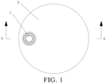
- a sealing assembly is provided in an embodiment, as shown in FIG. 1 to FIG. 3 .
- the sealing assembly includes a sealing element 1 and a top cover 2.
- the sealing element 1 includes a connection portion 11 and a sealing portion 12 axially connected to each other, where the connection portion 11 is disposed protruding from the sealing portion 12 along a radial direction.
- the top cover 2 is provided with a first groove 21, where a liquid injection hole 22 is provided at a bottom of the first groove 21, and a ring riveting portion 24 is disposed protruding from a periphery of the first groove 21.
- the sealing portion 12 is inserted into the liquid injection hole 22 in an interference fit to define a first sealing.
- the ring riveting portion 24 is riveted to the connection portion 11, so that the ring riveting portion 24 is annularly pressed on a top surface of the connection portion 11. That is, a second sealing can be implemented between the ring riveting portion 24 and the connection portion 11.
- the above-mentioned rivet-sealing manner can greatly simplify a sealing process and ensure a sealing performance. Compared with a battery sealed with the glue particles and the sealing nails, the sealing performance of the battery utilizing the above-mentioned sealing assembly can be accurately judged in a sealing test.
- the top cover 2 is circular to be suitable for cylindrical batteries.
- both the connection portion 11 and the sealing portion 12 have a circular cross-section.
- the top cover 2 is further provided with a second groove 23 to facilitate a formation of the ring riveting portion 24, where the second groove 23 is annularly defined at the periphery of the first groove 21 at intervals, the ring riveting portion 24 is disposed between the first groove 21 and the second groove 23, and the ring riveting portion 24 is an annular protrusion portion between the first groove 21 and the second groove 23.
- the first groove 21 is a circular groove
- the second groove 23 is a toroidal groove
- the ring rivet portion 24 is a toroidal protrusion.
- connection portion 11 includes a boss portion 111 and an edge portion 112, where the edge portion 112 is annularly disposed on a side surface of the boss portion 111, and the ring riveting portion 24 is annularly pressed on the edge portion 112.
- a radial length A of the edge portion 112 ranges from 0.5 mm to 3 mm, that is, the radial length A is a horizontal distance from the side surface of the boss portion 111 to a side surface of the edge portion 112. Riveting strength will be affected if the A is too small, and riveting difficulty will be increased if the A is too large, so the A is defined to be within the above-mentioned range.
- a radial end surface of the edge portion 112 is spaced from a side surface of the ring riveting portion 24, that is, an annular avoidance space 200 is defined to prevent a too long length of the edge portion 112 from affecting a riveting pressure of the ring riveting portion 24.
- the sealing assembly further includes a sealing ring 3 to improve the sealing performance.
- the sealing ring 3 is sleeved on the sealing portion 12 and abutted against the bottom of the first groove 21.
- An upper side surface of the sealing ring 3 is abutted against a bottom surface of the boss portion 111, and a lower side surface of the sealing ring 3 is abutted against the bottom of the first groove 21, that is a third sealing can be implemented.
- a side wall of the first groove 21 is obliquely disposed before the ring riveting portion 24 is riveted, so that a width of a notch of the first groove 21 is greater than a width of the bottom of the first groove 21.
- the first groove 21 is a circular groove, and a diameter D1 of the notch of the first groove 21 ranges from 3 mm to 10 mm, and a diameter D2 of the bottom of the first groove 21 ranges from 2 mm to 9 mm.
- a depth H1 of the first groove 21 ranges from 0.5 mm to 1 mm.
- a depth H2 of the second groove 23 ranges from 0.5 mm to 1.5 mm.
- a radial width W of the second groove 23 ranges from 0.5 mm to 3 mm to facilitate a riveting operation.
- a diameter D3 of the liquid injection hole 22 ranges from 1.5 mm to 5 mm to facilitate liquid injection and sealing operations.
- the sealing assembly further includes a glue filling layer 4 to ensure the sealing performance of the sealing assembly.
- the glue filling layer 4 is partially covered on the sealing element 1 and the ring riveting portion 24, and partially filled in the first groove 21.
- an avoidance gap 100 is defined between the side surface of the boss portion 111 and the ring riveting portion 24 to prevent the boss portion 111 from hindering the riveting pressure of the ring riveting portion 24, and the glue filling layer 4 is partially filled in the avoidance gap 100.
- Another embodiment of the present application further provides a battery, including the above-mentioned sealing assembly.
- the battery can simplify a sealing process and ensure a sealing performance.
Landscapes
- Chemical & Material Sciences (AREA)
- Chemical Kinetics & Catalysis (AREA)
- Electrochemistry (AREA)
- General Chemical & Material Sciences (AREA)
- Engineering & Computer Science (AREA)
- Manufacturing & Machinery (AREA)
- Inorganic Chemistry (AREA)
- Sealing Battery Cases Or Jackets (AREA)
- Filling, Topping-Up Batteries (AREA)
Abstract
Description
- This application claims priority to
Chinese Patent Application No. 202221968740.0, filed on July 28, 2022 - The present application relates to the technical field of battery technologies, for example, to a sealing assembly and a battery.
- Liquid injection holes of cover plates of cylindrical batteries are sealed with sealing glue particles and sealing nails. That is, a first sealing is performed for the liquid injection holes with the sealing glue particles, and a second sealing is performed by welding the sealing nails in the liquid injection holes. Main defects of the above-mentioned structure are as following:
- 1, the above-mentioned process is complex and has higher cost;
- 2, since the sealing nails located on the cover plates are welded by laser, a problem of electrolyte volatilization exists at welding positions, which is easy to cause poor welding, resulting in degradation of a sealing performance.
- Therefore, a sealing assembly and a battery are urgently needed to solve the above problems.
- The present application provides a sealing assembly, which can simplify a sealing process and ensure a sealing performance, and the sealing performance can be accurately judged in a sealing test.
- In a first aspect, a sealing assembly is provided in embodiments of the present application, including:
- a sealing element, the sealing element including a connection portion and a sealing portion axially connected to each other, where the connection portion is disposed protruding from the sealing portion along a radial direction; and
- a top cover, the top cover being provided with a first groove, where a liquid injection hole is provided at a bottom of the first groove, a ring riveting portion is disposed protruding from a periphery of the first groove, the sealing portion is inserted into the liquid injection hole in an interference fit, and the ring riveting portion is riveted to the connection portion, so that the ring riveting portion is annularly pressed on a top surface of the connection portion.
- In an embodiment, the top cover is further provided with a second groove, where the second groove is annularly defined at the periphery of the first groove at intervals, and the ring riveting portion is disposed between the first groove and the second groove.
- In an embodiment, the connection portion includes a boss portion and an edge portion, where the edge portion is annularly disposed on a side surface of the boss portion, and the ring riveting portion is annularly pressed on the edge portion.
- In an embodiment, the sealing assembly further includes a sealing ring, where the sealing ring is sleeved on the sealing portion and abutted against the bottom of the first groove.
- In an embodiment, a side wall of the first groove is obliquely disposed before the ring riveting portion is riveted, so that a width of a notch of the first groove is greater than a width of the bottom of the first groove.
- In an embodiment, the first groove is a circular groove, a diameter D1 of the notch of the first groove ranges from 3 mm to 10 mm, and a diameter D2 of the bottom of the first groove ranges from 2 mm to 9 mm.
- In an embodiment, a depth H1 of the first groove ranges from 0.5 mm to 1 mm.
- In an embodiment, a depth H2 of the second groove ranges from 0.5mm to 1.5mm, and a radial width W of the second groove ranges from 0.5 mm to 3 mm.
- In an embodiment, a radial end surface of the edge portion is spaced from a side surface of the ring riveting portion.
- In an embodiment, a radial length A of the edge portion ranges from 0.5 mm to 3 mm.
- In an embodiment, the seal assembly further includes a glue filling layer, where the glue filling layer is partially covered on the sealing element and the ring riveting portion, and partially filled in the first groove.
- In an embodiment, the seal assembly further includes a glue filling layer, where the glue filling layer is partially covered on the sealing element and the ring riveting portion, and partially filled in the first groove; an avoidance gap is defined between the side surface of the boss portion and the ring riveting portion, and the glue filling layer is partially filled in the avoidance gap. A battery is provided in the present application, which can simplify a sealing process and ensure a sealing performance.
- In a second aspect, a battery is provided in embodiments of the present application, including any one of the above-mentioned sealing assemblies.
- Beneficial effects according to the present application:
the sealing assembly is provided in the present application, including the sealing element and the top cover. The sealing element includes the connection portion and the sealing portion axially connected to each other, where the connection portion is disposed protruding from the sealing portion along the radial direction. The top cover is provided with the first groove, where the liquid injection hole is provided at the bottom of the first groove, the ring riveting portion is disposed protruding from the periphery of the first groove, the sealing portion is inserted into the liquid injection hole in an interference fit, and the ring riveting portion is riveted to the connection portion, so that the ring riveting portion is annularly pressed on the top surface of the connection portion. The above-mentioned rivet-sealing manner can greatly simplify the sealing process and ensure the sealing performance. - A battery is further provided in the present application, including the above-mentioned sealing assembly. The battery can greatly simplify a sealing process and ensure a sealing performance.
-
-
FIG. 1 is a schematic structural diagram of a sealing assembly provided in an embodiment of the present application. -
FIG. 2 is a sectional view ofFIG. 1 taken along A-A. -
FIG. 3 is a partial sectional view of a sealing assembly provided in the embodiment of the present application before it is riveted. -
- 1, sealing element; 11, connection portion; 111, boss portion; 112, edge portion; 12, sealing portion;
- 2, top cover; 21, first groove; 22, liquid injection hole; 23, second groove; 24, ring riveting portion;
- 3, sealing ring;
- 4, glue filling layer;
- 100, avoidance clearance; 200, avoidance space.
- In the description of the present application, unless otherwise specified and limited, the terms "fix", "link" or "connect" are to be construed in a broad sense, for example, as fixedly connected, detachably connected, or integrated; mechanically connected or electrically connected; directly connected to each other or indirectly connected to each other via an intermediary; or internally connected between two elements or interacted between two elements. Meanings of the preceding terms in the present application may be understood according to situations by an ordinary person in the art.
- In the present application, unless otherwise specified and limited, when a first feature is described as "on" or "below" a second feature, the first feature and the second feature may be in direct contact, or be in contact via another feature between the two features instead of being in direct contact. Moreover, when the first feature is described as "on", "above" or "over" the second feature, the first feature is right on, above or over the second feature or the first feature is obliquely on, above or over the second feature, or the first feature is simply at a higher level than the second feature. When the first feature is described as "under", "below" or "underneath" the second feature, the first feature is right under, below or underneath the second feature, or the first feature is obliquely under, below or underneath the second feature, or the first feature is simply at a lower level than the second feature.
- A sealing assembly is provided in an embodiment, as shown in
FIG. 1 to FIG. 3 . The sealing assembly includes asealing element 1 and atop cover 2. Thesealing element 1 includes aconnection portion 11 and a sealingportion 12 axially connected to each other, where theconnection portion 11 is disposed protruding from the sealingportion 12 along a radial direction. Thetop cover 2 is provided with afirst groove 21, where aliquid injection hole 22 is provided at a bottom of thefirst groove 21, and a ring rivetingportion 24 is disposed protruding from a periphery of thefirst groove 21. The sealingportion 12 is inserted into theliquid injection hole 22 in an interference fit to define a first sealing. The ring rivetingportion 24 is riveted to theconnection portion 11, so that the ring rivetingportion 24 is annularly pressed on a top surface of theconnection portion 11. That is, a second sealing can be implemented between the ring rivetingportion 24 and theconnection portion 11. The above-mentioned rivet-sealing manner can greatly simplify a sealing process and ensure a sealing performance. Compared with a battery sealed with the glue particles and the sealing nails, the sealing performance of the battery utilizing the above-mentioned sealing assembly can be accurately judged in a sealing test. - In an embodiment, the
top cover 2 is circular to be suitable for cylindrical batteries. In the embodiment, both theconnection portion 11 and thesealing portion 12 have a circular cross-section. - In an embodiment, the
top cover 2 is further provided with asecond groove 23 to facilitate a formation of the ring rivetingportion 24, where thesecond groove 23 is annularly defined at the periphery of thefirst groove 21 at intervals, the ring rivetingportion 24 is disposed between thefirst groove 21 and thesecond groove 23, and the ring rivetingportion 24 is an annular protrusion portion between thefirst groove 21 and thesecond groove 23. In the embodiment, thefirst groove 21 is a circular groove, thesecond groove 23 is a toroidal groove, and thering rivet portion 24 is a toroidal protrusion. - In an embodiment, the
connection portion 11 includes aboss portion 111 and anedge portion 112, where theedge portion 112 is annularly disposed on a side surface of theboss portion 111, and the ringriveting portion 24 is annularly pressed on theedge portion 112. In an embodiment, a radial length A of theedge portion 112 ranges from 0.5 mm to 3 mm, that is, the radial length A is a horizontal distance from the side surface of theboss portion 111 to a side surface of theedge portion 112. Riveting strength will be affected if the A is too small, and riveting difficulty will be increased if the A is too large, so the A is defined to be within the above-mentioned range. In an embodiment, a radial end surface of theedge portion 112 is spaced from a side surface of the ringriveting portion 24, that is, anannular avoidance space 200 is defined to prevent a too long length of theedge portion 112 from affecting a riveting pressure of the ringriveting portion 24. - In an embodiment, the sealing assembly further includes a
sealing ring 3 to improve the sealing performance. The sealingring 3 is sleeved on the sealingportion 12 and abutted against the bottom of thefirst groove 21. An upper side surface of the sealingring 3 is abutted against a bottom surface of theboss portion 111, and a lower side surface of the sealingring 3 is abutted against the bottom of thefirst groove 21, that is a third sealing can be implemented. - As shown in
FIG. 3 , in an embodiment, a side wall of thefirst groove 21 is obliquely disposed before the ringriveting portion 24 is riveted, so that a width of a notch of thefirst groove 21 is greater than a width of the bottom of thefirst groove 21. In an embodiment, thefirst groove 21 is a circular groove, and a diameter D1 of the notch of thefirst groove 21 ranges from 3 mm to 10 mm, and a diameter D2 of the bottom of thefirst groove 21 ranges from 2 mm to 9 mm. - In an embodiment, a depth H1 of the
first groove 21 ranges from 0.5 mm to 1 mm. In an embodiment, a depth H2 of thesecond groove 23 ranges from 0.5 mm to 1.5 mm. In an embodiment, a radial width W of thesecond groove 23 ranges from 0.5 mm to 3 mm to facilitate a riveting operation. - In an embodiment, a diameter D3 of the
liquid injection hole 22 ranges from 1.5 mm to 5 mm to facilitate liquid injection and sealing operations. - The sealing assembly further includes a
glue filling layer 4 to ensure the sealing performance of the sealing assembly. Theglue filling layer 4 is partially covered on the sealingelement 1 and the ringriveting portion 24, and partially filled in thefirst groove 21. In an embodiment, anavoidance gap 100 is defined between the side surface of theboss portion 111 and the ringriveting portion 24 to prevent theboss portion 111 from hindering the riveting pressure of the ringriveting portion 24, and theglue filling layer 4 is partially filled in theavoidance gap 100. - Another embodiment of the present application further provides a battery, including the above-mentioned sealing assembly. The battery can simplify a sealing process and ensure a sealing performance.
Claims (13)
- A sealing assembly, comprising:a sealing element (1), the sealing element (1) comprising a connection portion (11) and a sealing portion (12) axially connected to each other, wherein the connection portion (11) is disposed protruding from the sealing portion (12) along a radial direction; anda top cover (2), the top cover (2) being provided with a first groove (21), wherein a liquid injection hole (22) is provided at a bottom of the first groove (21), a ring riveting portion (24) is disposed protruding from a periphery of the first groove (21), the sealing portion (12) is inserted into the liquid injection hole (22) in an interference fit, and the ring riveting portion (24) is riveted to the connection portion (11), so that the ring riveting portion (24) is annularly pressed on a top surface of the connection portion (11).
- The sealing assembly of claim 1, wherein the top cover (2) is further provided with a second groove (23), wherein the second groove (23) is annularly defined at the periphery of the first groove (21) at intervals, and the ring riveting portion (24) is disposed between the first groove (21) and the second groove (23).
- The sealing assembly of claim 1, wherein the connection portion (11) comprises a boss portion (111) and an edge portion (112), wherein the edge portion (112) is annularly disposed on a side surface of the boss portion (111), and the ring riveting portion (24) is annularly pressed on the edge portion (112).
- The sealing assembly of claim 1, further comprising a sealing ring (3), wherein the sealing ring (3) is sleeved on the sealing portion (12) and abutted against the bottom of the first groove (21).
- The sealing assembly of any one of claim 1 to claim 4, wherein a side wall of the first groove (21) is obliquely disposed before the ring riveting portion (24) is riveted, so that a width of a notch of the first groove (21) is greater than a width of the bottom of the first groove (21).
- The sealing assembly of claim 5, wherein the first groove (21) is a circular groove, a diameter D1 of the notch of the first groove (21) ranges from 3 mm to 10 mm, and a diameter D2 of the bottom of the first groove (21) ranges from 2 mm to 9 mm.
- The sealing assembly of any one of claim 1 to claim 4, wherein a depth H1 of the first groove (21) ranges from 0.5 mm to 1 mm.
- The sealing assembly of claim 2, wherein a depth H2 of the second groove (23) ranges from 0.5mm to 1.5mm, and a radial width W of the second groove (23) ranges from 0.5 mm to 3 mm.
- The sealing assembly of claim 3, wherein a radial end surface of the edge portion (112) is spaced from a side surface of the ring riveting portion (24).
- The sealing assembly of claim 3, wherein a radial length A of the edge portion (112) ranges from 0.5 mm to 3 mm.
- The sealing assembly of any one of claim 1 to claim 4, further comprising a glue filling layer (4), wherein the glue filling layer (4) is partially covered on the sealing element (1) and the ring riveting portion (24), and partially filled in the first groove (21).
- The sealing assembly of claim 3, further comprising a glue filling layer (4), wherein the glue filling layer (4) is partially covered on the sealing element (1) and the ring riveting portion (24), and partially filled in the first groove (21); an avoidance gap (100) is defined between the side surface of the boss portion (111) and the ring riveting portion (24), and the glue filling layer (4) is partially filled in the avoidance gap (100).
- A battery, comprising the sealing assembly of any one of claim 1 to claim 12.
Applications Claiming Priority (2)
| Application Number | Priority Date | Filing Date | Title |
|---|---|---|---|
| CN202221968740.0U CN218039760U (en) | 2022-07-28 | 2022-07-28 | A sealed component and battery |
| PCT/CN2022/124893 WO2024021313A1 (en) | 2022-07-28 | 2022-10-12 | Sealing assembly and battery |
Publications (2)
| Publication Number | Publication Date |
|---|---|
| EP4343959A1 true EP4343959A1 (en) | 2024-03-27 |
| EP4343959A4 EP4343959A4 (en) | 2024-09-18 |
Family
ID=84341029
Family Applications (1)
| Application Number | Title | Priority Date | Filing Date |
|---|---|---|---|
| EP22821840.0A Pending EP4343959A4 (en) | 2022-07-28 | 2022-10-12 | Sealing assembly and battery |
Country Status (6)
| Country | Link |
|---|---|
| US (1) | US12500300B2 (en) |
| EP (1) | EP4343959A4 (en) |
| CN (1) | CN218039760U (en) |
| DE (1) | DE212022000398U1 (en) |
| HU (1) | HU6016U (en) |
| WO (1) | WO2024021313A1 (en) |
Families Citing this family (1)
| Publication number | Priority date | Publication date | Assignee | Title |
|---|---|---|---|---|
| CN115411470A (en) * | 2022-09-29 | 2022-11-29 | 宾科精密部件(中国)有限公司 | Battery filling opening sealing structure, sealing assembly and battery monomer |
Family Cites Families (9)
| Publication number | Priority date | Publication date | Assignee | Title |
|---|---|---|---|---|
| JP2007018915A (en) * | 2005-07-08 | 2007-01-25 | Nec Tokin Corp | Sealed battery |
| CN207818752U (en) | 2017-12-19 | 2018-09-04 | 比亚迪股份有限公司 | Liquid injection hole sealing device, cover assembly, battery, battery module and automobile |
| CN108847459B (en) | 2018-06-04 | 2021-08-31 | 常州瑞德丰精密技术有限公司 | Surface welding-free top cover assembly process |
| KR20200111498A (en) * | 2019-03-19 | 2020-09-29 | 삼성에스디아이 주식회사 | Secondary Battery |
| CN209675395U (en) | 2019-06-14 | 2019-11-22 | 宁德时代新能源科技股份有限公司 | Top cover assembly and secondary battery |
| CN210006772U (en) * | 2019-08-29 | 2020-01-31 | 宁德时代新能源科技股份有限公司 | Top cap assembly and secondary battery |
| CN214411464U (en) | 2021-02-02 | 2021-10-15 | 上海瑞浦青创新能源有限公司 | Sealing structure for lithium battery liquid injection hole |
| CN114006094B (en) * | 2021-10-27 | 2024-05-24 | 深圳市乐贝可科技有限公司 | Welding-free sealed type battery cell cover plate |
| CN217009358U (en) | 2022-01-06 | 2022-07-19 | 宜宾长盈精密技术有限公司 | Power battery top cover |
-
2022
- 2022-07-28 CN CN202221968740.0U patent/CN218039760U/en active Active
- 2022-10-12 HU HUU2400227U patent/HU6016U/en unknown
- 2022-10-12 US US18/002,856 patent/US12500300B2/en active Active
- 2022-10-12 EP EP22821840.0A patent/EP4343959A4/en active Pending
- 2022-10-12 WO PCT/CN2022/124893 patent/WO2024021313A1/en not_active Ceased
- 2022-10-12 DE DE212022000398.5U patent/DE212022000398U1/en active Active
Also Published As
| Publication number | Publication date |
|---|---|
| EP4343959A4 (en) | 2024-09-18 |
| US20240243454A1 (en) | 2024-07-18 |
| CN218039760U (en) | 2022-12-13 |
| US12500300B2 (en) | 2025-12-16 |
| DE212022000398U1 (en) | 2025-01-30 |
| HU6016U (en) | 2026-03-28 |
| WO2024021313A1 (en) | 2024-02-01 |
Similar Documents
| Publication | Publication Date | Title |
|---|---|---|
| CN101409332B (en) | Sealed battery | |
| US10950829B2 (en) | Sealing body of cylindrical battery, and cylindrical battery | |
| US6001504A (en) | Prismatic battery housing | |
| JP2009259651A (en) | Manufacturing method of sealed battery | |
| KR20110035868A (en) | Secondary battery | |
| EP4307457A1 (en) | Junction plate, battery, battery module and battery pack | |
| JP2020136105A (en) | Secondary battery | |
| US12500300B2 (en) | Sealing assembly and battery | |
| US20230037722A1 (en) | Electrical storage module | |
| JP5344603B2 (en) | battery | |
| EP4250440B1 (en) | Cylindrical battery | |
| US10381631B2 (en) | Sealed-type battery having a current interrupt device | |
| US20230352779A1 (en) | Power storage device and producing method therefor | |
| US20100040945A1 (en) | Battery cell case and battery cell | |
| EP4164037A1 (en) | Battery and method of manufacturing same | |
| JP5058562B2 (en) | Sealed battery | |
| EP4350876A1 (en) | Battery cover plate and battery | |
| EP4411975A1 (en) | Electricity storage device and method for manufacturing electricity storage device | |
| JPH0340373A (en) | Button type lithium battery | |
| CN223245857U (en) | Top cap module and battery | |
| CN219040659U (en) | Battery with explosion-proof structure | |
| EP4700973A1 (en) | Battery top cover, battery and electric device | |
| US20230318100A1 (en) | Power storage device and producing method therefor | |
| CN223193879U (en) | Cover plate assembly, single battery and electric equipment | |
| CN223471745U (en) | Battery cover plate structure and battery |
Legal Events
| Date | Code | Title | Description |
|---|---|---|---|
| STAA | Information on the status of an ep patent application or granted ep patent |
Free format text: STATUS: UNKNOWN |
|
| STAA | Information on the status of an ep patent application or granted ep patent |
Free format text: STATUS: THE INTERNATIONAL PUBLICATION HAS BEEN MADE |
|
| PUAI | Public reference made under article 153(3) epc to a published international application that has entered the european phase |
Free format text: ORIGINAL CODE: 0009012 |
|
| STAA | Information on the status of an ep patent application or granted ep patent |
Free format text: STATUS: REQUEST FOR EXAMINATION WAS MADE |
|
| 17P | Request for examination filed |
Effective date: 20221220 |
|
| AK | Designated contracting states |
Kind code of ref document: A1 Designated state(s): AL AT BE BG CH CY CZ DE DK EE ES FI FR GB GR HR HU IE IS IT LI LT LU LV MC ME MK MT NL NO PL PT RO RS SE SI SK SM TR |
|
| A4 | Supplementary search report drawn up and despatched |
Effective date: 20240820 |
|
| RIC1 | Information provided on ipc code assigned before grant |
Ipc: H01M 50/107 20210101ALI20240813BHEP Ipc: H01M 50/645 20210101AFI20240813BHEP |
|
| DAV | Request for validation of the european patent (deleted) | ||
| DAX | Request for extension of the european patent (deleted) |