EP4343930A1 - Metal-air battery system - Google Patents
Metal-air battery system Download PDFInfo
- Publication number
- EP4343930A1 EP4343930A1 EP22832926.4A EP22832926A EP4343930A1 EP 4343930 A1 EP4343930 A1 EP 4343930A1 EP 22832926 A EP22832926 A EP 22832926A EP 4343930 A1 EP4343930 A1 EP 4343930A1
- Authority
- EP
- European Patent Office
- Prior art keywords
- electrode
- positive electrode
- metal
- battery system
- air battery
- Prior art date
- Legal status (The legal status is an assumption and is not a legal conclusion. Google has not performed a legal analysis and makes no representation as to the accuracy of the status listed.)
- Granted
Links
Images



Classifications
-
- H—ELECTRICITY
- H01—ELECTRIC ELEMENTS
- H01M—PROCESSES OR MEANS, e.g. BATTERIES, FOR THE DIRECT CONVERSION OF CHEMICAL ENERGY INTO ELECTRICAL ENERGY
- H01M12/00—Hybrid cells; Manufacture thereof
- H01M12/08—Hybrid cells; Manufacture thereof composed of a half-cell of a fuel-cell type and a half-cell of the secondary-cell type
-
- H—ELECTRICITY
- H01—ELECTRIC ELEMENTS
- H01M—PROCESSES OR MEANS, e.g. BATTERIES, FOR THE DIRECT CONVERSION OF CHEMICAL ENERGY INTO ELECTRICAL ENERGY
- H01M12/00—Hybrid cells; Manufacture thereof
- H01M12/04—Hybrid cells; Manufacture thereof composed of a half-cell of the fuel-cell type and of a half-cell of the primary-cell type
- H01M12/06—Hybrid cells; Manufacture thereof composed of a half-cell of the fuel-cell type and of a half-cell of the primary-cell type with one metallic and one gaseous electrode
-
- H—ELECTRICITY
- H01—ELECTRIC ELEMENTS
- H01M—PROCESSES OR MEANS, e.g. BATTERIES, FOR THE DIRECT CONVERSION OF CHEMICAL ENERGY INTO ELECTRICAL ENERGY
- H01M10/00—Secondary cells; Manufacture thereof
- H01M10/04—Construction or manufacture in general
- H01M10/0445—Multimode batteries, e.g. containing auxiliary cells or electrodes switchable in parallel or series connections
-
- H—ELECTRICITY
- H01—ELECTRIC ELEMENTS
- H01M—PROCESSES OR MEANS, e.g. BATTERIES, FOR THE DIRECT CONVERSION OF CHEMICAL ENERGY INTO ELECTRICAL ENERGY
- H01M4/00—Electrodes
- H01M4/02—Electrodes composed of, or comprising, active material
- H01M4/64—Carriers or collectors
- H01M4/70—Carriers or collectors characterised by shape or form
- H01M4/76—Containers for holding the active material, e.g. tubes, capsules
- H01M4/765—Tubular type or pencil type electrodes; tubular or multitubular sheaths or covers of insulating material for said tubular-type electrodes
-
- H—ELECTRICITY
- H01—ELECTRIC ELEMENTS
- H01M—PROCESSES OR MEANS, e.g. BATTERIES, FOR THE DIRECT CONVERSION OF CHEMICAL ENERGY INTO ELECTRICAL ENERGY
- H01M50/00—Constructional details or processes of manufacture of the non-active parts of electrochemical cells other than fuel cells, e.g. hybrid cells
- H01M50/10—Primary casings; Jackets or wrappings
- H01M50/102—Primary casings; Jackets or wrappings characterised by their shape or physical structure
- H01M50/107—Primary casings; Jackets or wrappings characterised by their shape or physical structure having curved cross-section, e.g. round or elliptic
-
- H—ELECTRICITY
- H01—ELECTRIC ELEMENTS
- H01M—PROCESSES OR MEANS, e.g. BATTERIES, FOR THE DIRECT CONVERSION OF CHEMICAL ENERGY INTO ELECTRICAL ENERGY
- H01M8/00—Fuel cells; Manufacture thereof
- H01M8/02—Details
- H01M8/0202—Collectors; Separators, e.g. bipolar separators; Interconnectors
- H01M8/023—Porous and characterised by the material
-
- Y—GENERAL TAGGING OF NEW TECHNOLOGICAL DEVELOPMENTS; GENERAL TAGGING OF CROSS-SECTIONAL TECHNOLOGIES SPANNING OVER SEVERAL SECTIONS OF THE IPC; TECHNICAL SUBJECTS COVERED BY FORMER USPC CROSS-REFERENCE ART COLLECTIONS [XRACs] AND DIGESTS
- Y02—TECHNOLOGIES OR APPLICATIONS FOR MITIGATION OR ADAPTATION AGAINST CLIMATE CHANGE
- Y02E—REDUCTION OF GREENHOUSE GAS [GHG] EMISSIONS, RELATED TO ENERGY GENERATION, TRANSMISSION OR DISTRIBUTION
- Y02E60/00—Enabling technologies; Technologies with a potential or indirect contribution to GHG emissions mitigation
- Y02E60/10—Energy storage using batteries
-
- Y—GENERAL TAGGING OF NEW TECHNOLOGICAL DEVELOPMENTS; GENERAL TAGGING OF CROSS-SECTIONAL TECHNOLOGIES SPANNING OVER SEVERAL SECTIONS OF THE IPC; TECHNICAL SUBJECTS COVERED BY FORMER USPC CROSS-REFERENCE ART COLLECTIONS [XRACs] AND DIGESTS
- Y02—TECHNOLOGIES OR APPLICATIONS FOR MITIGATION OR ADAPTATION AGAINST CLIMATE CHANGE
- Y02E—REDUCTION OF GREENHOUSE GAS [GHG] EMISSIONS, RELATED TO ENERGY GENERATION, TRANSMISSION OR DISTRIBUTION
- Y02E60/00—Enabling technologies; Technologies with a potential or indirect contribution to GHG emissions mitigation
- Y02E60/30—Hydrogen technology
- Y02E60/50—Fuel cells
Definitions
- the present disclosure relates to a metal-air battery system.
- Patent Document 1 describes a cylindrical three-electrode metal-air battery system in which a cylindrical fuel electrode, auxiliary electrode, and air electrode immersed in an electrolyte solution are concentrically arranged.
- This metal-air battery system can be used as a secondary battery in which the fuel electrode and the auxiliary electrode are used to charge and the fuel electrode and the air electrode are used to discharge, and can be used as a fuel cell in which zinc pellets are introduced to the auxiliary electrode having a holding structure and the auxiliary electrode and the air electrode are used to generate electricity.
- Patent Document 1 JP2015-170400A
- the electrolyte solution is stored in a tank, and the electrolyte solution is supplied in circulation by a pump.
- the electrolyte solution is not configured to be supplied in circulation, and if the electrolyte solution is configured to be supplied in circulation, the zinc pellets introduced to the auxiliary electrode may flow away along with the electrolyte solution. Therefore, it is not envisaged that the metal-air battery system of Patent Document 1 would be modified such that the electrolyte solution is supplied in circulation, and further such modification cannot be made easily.
- an object of at least one embodiment of the present disclosure is to provide a metal-air battery system that can store electricity, and charge and discharge efficiently.
- a metal-air battery system that includes a cell including: a chamber; and an electrode device housed in the chamber.
- the electrode device includes: a first electrode; a tubular second electrode disposed so as to surround the first electrode on a radially outer side of the first electrode; and a tubular third electrode disposed so as to surround the second electrode on a radially outer side of the second electrode, and is configured such that an electrolyte solution flows at least between an outer peripheral surface of the first electrode and an inner peripheral surface of the third electrode.
- a combination of the first electrode, the second electrode, and the third electrode is a combination of a negative electrode containing metal, a charging positive electrode, and a discharging positive electrode.
- the metal-air battery system of the present disclosure since a difference in electrode area between the inner side and the outer side can be obtained by arranging electrodes such that their cross sections are concentric, it is possible to reduce a current density during operation of the electrodes arranged on the outer side compared to that of the central electrode.
- the resistance of the system can be reduced by utilizing this effect to arrange, on the outer side, the electrodes requiring a reduction in resistance loss, making it possible to efficiently charge/discharge.
- the electrolyte solution is supplied in circulation to the cell, electricity can be stored.
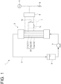
- a metal-air battery system 1 includes a cylindrical three-electrode cell 2. Both ends of a circulation line 3 for an electrolyte solution are connected to the cell 2 in order to flow the electrolyte solution inside the cell 2.
- the circulation line 3 includes an electrolytic tank 4 for storing the electrolyte solution, and a pump 5.
- the electrolyte solution it is possible to use either an aqueous electrolyte solution in which an electrolyte is dissolved in water or a non-aqueous electrolyte in which an electrolyte is dissolved in a non-aqueous solution such as an organic solvent.
- aqueous electrolyte solution it is possible to use, for example, an aqueous solution in which a hydroxide such as potassium, sodium, lithium, barium, or magnesium, a chloride, a phosphate, a borate, a sulfate, etc. is used as an electrolyte. That is, any indicator salt for imparting electrical conductivity of the aqueous solution can be used as the electrolyte.
- non-aqueous electrolyte solution it is possible to use, for example, a solution obtained by dissolving an indicator salt containing an alkali metal etc. in a liquid such as a cyclic or chain carbonate, a cyclic or chain ester, a cyclic or chain ether, a sulfone compound, an ionic liquid, etc.
- a solution obtained by dissolving an indicator salt containing an alkali metal etc. in a liquid such as a cyclic or chain carbonate, a cyclic or chain ester, a cyclic or chain ether, a sulfone compound, an ionic liquid, etc.
- the cell 2 includes an electrode device 10 that has a shape extending in the axial direction, and includes a first electrode 11, a tubular second electrode 12 disposed so as to surround the first electrode 11 on a radially outer side of the first electrode 11, and a tubular third electrode 13 disposed so as to surround the second electrode12 on a radially outer side of the second electrode.
- “surround” means a configuration in which at least a part of the first electrode 11 in a length direction and at least a part of the second electrode 12 in a length direction are housed inside the second electrode 12 and the third electrode 13, respectively.
- the first electrode 11, the second electrode 12, and the third electrode 13 are disposed such that their cross sections perpendicular to the axial direction have a concentric shape (a concentric circular shape if these electrodes are cylindrical).
- the first electrode 11 is a negative electrode 11a
- the second electrode 12 is a charging positive electrode 12a used together with the negative electrode 11a during charging of the metal-air battery system 1
- the third electrode 13 is a discharging positive electrode 13a used together with the negative electrode 11a during discharging of the metal-air battery system 1.
- the negative electrode 11a may be a tubular electrode made of metal such as zinc, or may be an electrode in which a surface of a tubular body made of other metal such as stainless steel or aluminum is plated with zinc. In the latter case, it is only necessary that at least an outer surface, of the surface of the negative electrode 11a, facing the charging positive electrode 12a is plated with zinc.
- the metal contained in the negative electrode 11a is not limited to zinc. Iron, aluminum, lithium, sodium, potassium, copper, magnesium, etc., or alloys thereof can be used depending on the type of electrolyte solution (for example, a difference in aqueous electrolyte solution/non-aqueous electrolyte solution).
- a tubular electrode made of a non-oxidizing porous metal material such as nickel, nickel alloy, or stainless steel in a mesh shape can be used as the charging positive electrode 12a.
- the discharging positive electrode 13a it is possible to use, for example, an electrode having a three-layer structure including a porous outermost layer in which oxygen can diffuse, a porous intermediate layer formed of metal such as nickel, and an innermost layer in which an oxygen reduction catalyst is supported on a conductive material such as carbon.
- a catalyst mainly containing platinum as an active component for example, platinum-supported carbon
- a catalyst can be used under an acidic liquid environment.
- a catalyst under an alkaline liquid environment, which contains 3d transition metal such as iron, manganese, nickel, or cobalt, or its oxide as an active component.
- a catalyst containing ruthenium, silver, gold, or iridium as an active component can also be used under both the acidic liquid environment and the alkaline liquid environment. Further, a catalyst can also be used, which contains an organometallic complex, a carbon fiber (for example, a carbon nanotube), a nitrogen carbide, etc. as an active component. Moreover, according to this configuration, since electrode areas of the charging positive electrode 12a and the discharging positive electrode 13a can be greater than that of the negative electrode 11a, a current density during charging/discharging can be lower than that of the negative electrode 11a. Whereby, it is possible to expect an effect of being able to relatively reduce a loss due to resistance of the charging positive electrode 12a and the discharging positive electrode 13a.
- the metal-air battery system 1 can further include a switching device 7.
- the negative electrode 11a is electrically connected to an AC/DC converter 6, and the charging positive electrode 12a and the discharging positive electrode 13a are connected to the AC/DC converter 6 via the switching device 7 which is switchable such that either one of the charging positive electrode 12a or the discharging positive electrode 13a energizes the AC/DC converter 6, that is, the negative electrode 11a is electrically connected to either one of the charging positive electrode 12a or the discharging positive electrode 13a.
- the AC/DC converter 6 can electrically be connected to a load 8 and an AC power source 9. The AC/DC converter 6 is not required if a DC power source is used in place of the AC power source 9 and the load 8 operates on DC current.
- the switching device 7 may be composed of a first switch 7c for electrically opening and closing between the discharging positive electrode 13a and the negative electrode 11a, and a second switch 7d for electrically opening and closing between the negative electrode 11a and the charging positive electrode 12a (hereinafter, referred to as the "switch-type switching device 7").
- the first switch 7c and the second switch 7d are not limited to mechanical switches, and may be semiconductor switches. Further, as shown in FIG.
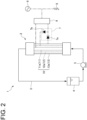
- the switching device 7 may be composed of a first diode 7a for flowing a current in a direction from the discharging positive electrode 13a to the negative electrode 11a, and a second diode 7b for flowing a current in a direction from the negative electrode 11a to the charging positive electrode 12a (hereinafter, referred to as the "diode-type switching device 7").
- the diode-type switching device 7 is superior in terms of durability and cost compared to the switch-type switching device 7 composed of the mechanical switches, and is superior in terms of cost compared to the switch-type switching device 7 composed of the semiconductor switches.
- the second diode 7b may not be provided (the switching device 7 is composed only of the first diode 7a). Also, the first diode 7a may not be provided, either (that is, a configuration in which the switching device 7 is not provided) if it is not necessary to consider the reaction at the discharging positive electrode 13a during charging.
- the cell 2 includes a chamber 20 for housing the electrode device 10.
- the chamber 20 includes a first chamber section 21 provided so as to internally house at least one end portion 13d1 of the third electrode 13 on a side of a first end portion 10a which is one end portion of the electrode device 10, and a second chamber section 22 provided so as to internally house at least another end portion 13d2 of the third electrode 13 on a side of a second end portion 10b which is another end portion of the electrode device 10.
- the first chamber section 21 has a first end face 21a and a second end face 21b located away from each other in the axial direction of the cell 2, and the first end face 21a and the second end face 21b are respectively formed with a first opening 23a and a second opening 23b.
- the second chamber section 22 has a third end face 22a and a fourth end face 22b located away from each other in the axial direction of the cell 2, and the third end face 22a and the fourth end face 22b are respectively formed with a third opening 24a and a fourth opening 24b.
- the first electrode 11, the second electrode 12, and the third electrode 13 are respectively inserted into the second opening 23b and the fourth opening 24b, and a seal member 25 for sealing between an outer peripheral surface of the third electrode 13 and respective inner peripheral surfaces of the first chamber section 21 and the second chamber section 22 is disposed therebetween.
- the seal member 25 can suppress leakage of the electrolyte solution from the chamber 20 between the first opening 23a and the third opening 24a.
- the seal member 25 may be an adhesive agent, a heat-shrinkable tube, a heat seal, a resin weld, or the like.
- the inner peripheral surface of the discharging positive electrode 13a that is, the surface facing the negative electrode 11a is provided with a separation membrane 26.
- a separation membrane 26 As the separation membrane 26, it is possible to use, for example, an anion exchange membrane, or a microporous membrane formed from polymer, solid oxide, or the like.
- the configuration of the anion exchange membrane is not particularly limited, it is preferable to use a high-performance membrane with high ion conductivity and strength.
- the configuration of the microporous membrane is not particularly limited, either and commercially available membranes for various purposes can be used.
- any resin-made microporous membrane can be used as long as hydrophilic treatment is applied to a surface, for example, modifying the surface with a hydrophilic group, adding a surfactant to the surface, or combining the surface with oxide particles.
- the pump 5 is started in a state where the switching device 7 is operated to electrically connect the negative electrode 11a to the discharging positive electrode 13a, and the electrolyte solution is supplied from the electrolytic tank 4 to the cell 2 via the circulation line 3.
- the electrolyte solution circulates through the circulation line 3 by returning to the electrolytic tank 4 via the circulation line 3 after passing through the cell 2.
- the electrolyte solution having flowed into the first chamber section 21 via the first opening 23a flows into, via the first end portion 10a of the electrode device 10, flow paths formed between the outer peripheral surface of the negative electrode 11a and the inner peripheral surface of the discharging positive electrode 13a, that is, a flow path formed between the outer peripheral surface of the negative electrode 11a and the inner peripheral surface of the charging positive electrode 12a and a flow path formed between the outer peripheral surface of the charging positive electrode 12a and the inner peripheral surface of the discharging positive electrode 13a, and flows through these flow paths.
- the electrolyte solution having flowed through these flow paths flows out from these flow paths to the second chamber section 22 via the second end portion 10b of the electrode device 10, and flows out from the second chamber section 22 via the third opening 24a.
- the following reaction occurs in the negative electrode 11a and the discharging positive electrode 13a.
- metal contained in the negative electrode 11a such as zinc, reacts with hydroxide ions in the electrolyte solution to generate zincate ions, and electrons are emitted to the negative electrode 11a and flow to the discharging positive electrode 13a.
- the discharging positive electrode 13a oxygen contained in air outside the cell 2 diffuses through the outermost layer and the intermediate layer, and hydroxide ions are produced by reactions between the air, water in the electrolyte solution, and the electrons flowing to the discharging positive electrode 13a due to the oxygen reduction catalyst in the innermost layer.
- the produced hydroxide ions are used in the above-described reaction at the negative electrode 11a.
- the anion exchange membrane which is the separation membrane 26 is provided on the inner peripheral surface of the discharging positive electrode 13a, that is, the innermost layer (a layer where the oxygen reduction catalyst is supported on the conductive material) of the discharging positive electrode 13a, oxygen molecules react at a reaction interface (three-phase interface) where the oxygen reduction catalyst/conductive material/ionic conductor contact, producing hydroxide ions.
- the produced hydroxide ions move into the electrolyte solution through the ionic conductor.
- the reaction interface by ionomer contact with the oxygen reduction catalyst is extended and the resistance is reduced.
- the separation membrane 26 is provided on the inner peripheral surface of the discharging positive electrode 13a, it is possible to suppress leakage of the electrolyte solution to the outside of the cell 2 via the discharging positive electrode 13a or clogging of the intermediate layer and the outermost layer of the discharging positive electrode 13a. Further, precipitation of carbonate from the electrolyte solution and clogging of the intermediate layer and the outermost layer of the discharging positive electrode 13a can be suppressed by suppressing mixing of carbon dioxide contained in the air into the electrolyte solution. Therefore, it is possible to reduce an overvoltage loss of the reaction in the discharging positive electrode 13a, and it is possible to suppress alteration, deterioration, or leakage of the electrolyte solution.
- the electrolyte solution is circulated in a state where the switching device 7 is operated to electrically connect the negative electrode 11a to the charging positive electrode 12a.
- the AC current from the AC power source 9 is converted into DC current by the AC/DC converter 6, and the DC current flows to the charging positive electrode 12a. That is, electrons flow to the negative electrode 11a.
- zinc ions in the electrolyte solution receive electrons, thereby depositing zinc on the negative electrode 11a, and the metal-air battery system 1 is charged.
- the negative electrode 11a is electrically connected to the discharging positive electrode 13a by closing the first switch 7c and opening the second switch 7d, thereby switching from the charging state to the discharging state. Even if the negative electrode 11a and the charging positive electrode 12a are internally short-circuited by the dendrite, the negative electrode 11a and the charging positive electrode 12a are electrically separated, allowing for discharge using the negative electrode 11a and the discharging positive electrode 13a. During discharging, zinc is eluted as zinc ions from the negative electrode 11a into the electrolyte solution, eliminating the internal short circuit.
- the difference in electrode area between the inner side and the outer side can be obtained by arranging the negative electrode 11a, the charging positive electrode 12a, and the discharging positive electrode 13a such that their cross sections are concentric, it is possible to reduce the current density during operation of the charging positive electrode 12a and the discharging positive electrode 13a arranged on the outer side compared to that of the central negative electrode 11a.
- the resistance of the system can be reduced by utilizing this effect to arrange the charging positive electrode 12a and the discharging positive electrode 13a, which require a reduction in resistance loss, on the outer side, making it possible to efficiently charge/discharge. Further, since the electrolyte solution is supplied in circulation to the cell, electricity can be stored.
- the switch-type switching device 7 since the switch-type switching device 7 is provided, the negative electrode 11a and the charging positive electrode 12a are used to charge and the negative electrode 11a and the discharging positive electrode 13a are used to discharge, making it possible to discharge even if internal short circuit occurs during charging. Whereby, it is possible to charge/discharge without any trouble. Further, since the electrolyte solution is supplied in circulation to the cell 2, electricity can be stored. On the other hand, since either the switch-type or diode-type switching device 7 is provided, it is possible to reduce the risk of opposite reactions occurring at the positive electrode during charging and discharging, and improvements in efficiency and lifetime can be expected.
- the negative electrode 11a does not have a tubular shape
- the negative electrode 11a may also have the tubular shape just like the charging positive electrode 12a and the discharging positive electrode 13a.
- the configuration is preferable in which the inner peripheral surface of the negative electrode 11a also contains zinc.
- the metal-air battery system according to Embodiment 2 is obtained by modifying the configuration of the electrode device 10 with respect to Embodiment 1.
- the same constituent elements as those in Embodiment 1 are associated with the same reference signs and not described again in detail.
- the cell 2 includes the electrode device 10 with a charging positive electrode 11b as the first electrode 11, a negative electrode 12b as the second electrode 12, and the discharging positive electrode 13a as the third electrode 13.
- the negative electrode 12b has a tubular shape, and the negative electrode 12b is configured to contain zinc not only on its outer peripheral surface but also on its inner peripheral surface.
- an electrode having a tubular shape manufactured in a mesh shape may be used as the charging positive electrode 11b.
- the charging positive electrode 11b will be described as an electrode having a non-mesh non-tubular shape, that is, a bar shape. Other configurations are the same as those in Embodiment 1.
- Embodiment 2 The operation in Embodiment 2 is the same as that in Embodiment 1. That is, in the metal-air battery system 1 according to Embodiment 2 as well, the negative electrode 12b and the charging positive electrode 11b are used to charge and the negative electrode 12b and the discharging positive electrode 13a are used to discharge, making it possible to discharge even if internal short circuit occurs during charging. In Embodiment 2 as well, since the charging positive electrode 11b, the negative electrode 12b, and the discharging positive electrode 13a are disposed such that their cross sections are concentric, the same technical effect as in Embodiment 1 can be obtained.
- a measuring instrument is provided to measure a potential difference between the negative electrode 12b and the discharging positive electrode 13a, and this potential difference is monitored during charging, making it possible to detect that internal short circuit has occurred between the negative electrode 12b and the discharging positive electrode 13a. If the internal short circuit between the negative electrode 12b and the discharging positive electrode 13a is detected, the internal short circuit can be eliminated by discharging using the negative electrode 12b and the charging positive electrode 11b.
- the metal-air battery system according to Embodiment 3 is obtained by modifying the configuration of the electrode device 10 with respect to Embodiment 1.
- the same constituent elements as those in Embodiment 1 are associated with the same reference signs and not described again in detail.
- the cell 2 includes the electrode device 10 with a discharging positive electrode 11c as the first electrode 11, the charging positive electrode 12a as the second electrode 12, and a negative electrode 13c as the third electrode 13. All of the discharging positive electrode 11c, the charging positive electrode 12a, and the negative electrode 13c have a tubular shape.
- An outer peripheral surface of the discharging positive electrode 11c, that is, a surface facing the negative electrode 13c is provided with the separation membrane 26.
- a three-layer structure of the discharging positive electrode 11c is different from that of the discharging positive electrode 13a (see FIG. 2 ) of Embodiments 1 and 2, and the layer where the oxygen reduction catalyst is supported on the conductive material such as carbon is the outermost layer on the outer peripheral surface side and the porous layer in which oxygen can diffuse is the innermost layer on the inner peripheral surface side.
- Each of the first chamber section 21 and the second chamber section 22 is internally provided with a separation member 30 for separating the flow of the electrolyte solution in the chamber 20 into a first flow F1 flowing inside the discharging positive electrode 11c and a second flow F2 flowing outside the discharging positive electrode 11c.
- the separation member 30 has a tubular shape in which end faces 31, 32 are disposed at both ends in the axial direction of the cell 2 when disposed inside the first chamber section 21 and the second chamber section 22, and openings 31a, 32a are respectively formed in the end faces 31, 32.
- the discharging positive electrode 11c is inserted into the one opening 32a, and a seal member 33 such as an O-ring is disposed between an inner peripheral edge of the opening 31b and an outer peripheral surface of the discharging positive electrode 11c.
- the other opening 31a faces the first opening 23a or the third opening 24a.
- An oxygen-containing gas supply device 34 is provided to supply an oxygen-containing gas such as air to the electrolyte solution of the first flow F1 inside the separation member 30 disposed in, among the first chamber section 21 and the second chamber section 22, the first chamber section 21 located upstream in the flow direction of the electrolyte solution flowing in the cell 2.
- an oxygen-containing gas supply device 34 it is possible to use, for example, a bubbling device that includes an oxygen-containing gas supply line 35 having one end located inside the separation member 30 and another end opening to the outside of the cell 2 or connected to an oxygen-containing gas cylinder or the like, and a compressor 36 disposed on the oxygen-containing gas supply line 35.
- Other configurations are the same as those in Embodiment 1.
- the operation of the metal-air battery system 1 according to Embodiment 3 will be described, focusing on differences from the operation of the metal-air battery system 1 according to Embodiment 1.
- the electrolyte solution having flowed into the first chamber section 21 via the first opening 23a is divided into the first flow F1 which is a flow of the electrolyte solution entering the inside of the separation member 30 via the opening 31a and the second flow F2 which is a flow of the electrolyte solution outside the separation member 30.
- the oxygen-containing gas pressurized by the compressor 36 is supplied into the separation member 30 via the oxygen-containing gas supply line 35, thereby bubbling the oxygen-containing gas into the electrolyte solution. Consequently, the electrolyte solution in which oxygen is dissolved flows inside the discharging positive electrode 11c as the first flow F1.
- the electrolyte solution outside the separation member 30 flows, as the second flow F2, through a flow path formed between an outer peripheral surface of the discharging positive electrode 11c and the inner peripheral surface of the charging positive electrode 12a and a flow path formed between the outer peripheral surface of the charging positive electrode 12a and the inner peripheral surface of the negative electrode 13c.
- the electrolyte solution of the first flow F1 flows out from the inside of the discharging positive electrode 11c to the inside of the separation member 30 disposed in the second chamber section 22, and flows out from the inside of the separation member 30 via the opening 31a.
- the electrolyte solution of the second flow F2 flows out to the second chamber section 22 via the second end portion 10b of the electrode device 10.
- the electrolyte solution where the first flow F1 and the second flow F2 join in the second chamber section 22 flows out from the second chamber section 22 via the third opening 24a.
- the first flow F1 and the second flow F2 may flow out separately from the second chamber section 22 without being joined.
- Embodiment 3 is the same as Embodiment 1 in that the discharging positive electrode 11c, the charging positive electrode 12a, and the negative electrode 13c are disposed such that their cross sections are concentric. Further, Embodiment 3 is the same as Embodiment 1 in that when the metal-air battery system 1 is charged, electrons flow to the negative electrode 13c and zinc ions in the electrolyte solution receive the electrons at the negative electrode 13c, thereby depositing zinc on the negative electrode 13c.
- Embodiment 3 is the same as Embodiment 1 in that when the metal-air battery system 1 is charged, even if the dendrite connecting the negative electrode 13c and the charging positive electrode 12a causes an internal short circuit, discharge using the negative electrode 13c and the discharging positive electrode 11c is possible. Therefore, Embodiment 3 can also obtain the same technical effect as the technical effect obtained in Embodiment 1.
- Embodiment 3 since the third electrode 13 arranged on the outermost side in the electrode device 10 is the negative electrode 13c, the area of the negative electrode relatively increases compared to a case where the first electrode 11 or the second electrode 12 is the negative electrode. Therefore, the amount of zinc deposited on the negative electrode 13c in Embodiment 3 increases compared to Embodiment 1, making it possible to increase an electricity storage capacity compared to Embodiment 1.
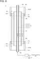
- an oxygen-containing gas flow F3 flows inside the discharging positive electrode 11c. Also in this form, while the electrolyte solution and the oxygen-containing gas circulate in the cell 2, discharge is performed by the same reaction as in Embodiment 3. Further, the charging operation is also the same as in Embodiment 3. Therefore, also in this modified example, the same technical effect as in Embodiment 3 can be obtained.
- the oxygen-containing gas is flowed inside the discharging positive electrode 11c, but the present disclosure is not limited to this form.
- the electrolyte solution in which oxygen is dissolved may be flowed inside the discharging positive electrode 11c as the first flow F1.
- the both ends of the discharging positive electrode 11c are connected to both ends of a circulation line 40 where the electrolyte solution circulates.
- the circulation line 40 includes an electrolytic tank 41 for storing the electrolyte solution, and a pump 42.
- the circulation line 40, the electrolytic tank 41, and the pump 42 are disposed separately from the circulation line 3 (see FIG. 1 ), the electrolytic tank 4 (see FIG. 1 ), and the pump 5 (see FIG. 1 ), respectively.
- the electrolytic tank 41 is provided with a bubbling device 43 for supplying an oxygen-containing gas into the electrolyte solution stored in the electrolytic tank 41 while bubbling the oxygen-containing gas.
- the electrolyte solution of the first flow F1 can be an electrolyte solution in which oxygen is dissolved.
- either the gas containing oxygen or the electrolyte solution containing oxygen may flow inside the discharging positive electrode 11c. That is, a fluid containing oxygen can be flowed inside the discharging positive electrode 11c.
- the configuration including the oxygen-containing gas supply line 35 and the compressor 36 or the configuration including the circulation line 40, the electrolytic tank 41, the pump 42, and the bubbling device 43 is an oxygen-containing fluid supply device 37 for flowing, inside the discharging positive electrode 11c, the fluid containing oxygen.
- the metal-air battery system according to Embodiment 4 is obtained by modifying the configuration of the electrode device 10 with respect to Embodiment 3.
- the same constituent elements as those in Embodiment 3 are associated with the same reference signs and not described again in detail.
- the cell 2 includes the electrode device 10 with the discharging positive electrode 11c as the first electrode 11, the negative electrode 12b as the second electrode 12, and a charging positive electrode 13b as the third electrode 13. All of the discharging positive electrode 11c, the negative electrode 12b, and the charging positive electrode 13b have a tubular shape.
- the charging positive electrode 13b will be described not as an electrode having a tubular shape manufactured in a mesh shape as in Embodiment 1 but as an electrode having a non-mesh tubular shape. Other configurations are the same as those in Embodiment 3.
- Embodiment 4 Since the operation of Embodiment 4 and the operation of Embodiment 3 are the same, the same technical effect as in Embodiment 3 can be obtained. Further, in Embodiment 4 as well, since the charging positive electrode 11b, the negative electrode 12b, and the discharging positive electrode 13a are disposed such that their cross sections are concentric, the same technical effect as in Embodiment 1 can be obtained.
- a measuring instrument is provided to measure a potential difference between the negative electrode 12b and the discharging positive electrode 11c, and this potential difference is monitored during charging, making it possible to detect that internal short circuit has occurred between the negative electrode 12b and the discharging positive electrode 11c. If the internal short circuit between the negative electrode 12b and the discharging positive electrode 11c is detected, the internal short circuit can be eliminated by discharging using the negative electrode 12b and the charging positive electrode 13b.
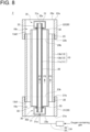
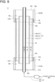
- Embodiment 4 as well, as in Embodiment 3, a modified example is possible in which, instead of the first flow F1 of the electrolyte solution flowing inside the discharging positive electrode 11c, the oxygen-containing gas flow F3 is used as shown in FIG. 9 . Further, by applying the configuration shown in FIG. 7 to this modified example, the electrolyte solution in which oxygen is dissolved can also be used as the first flow F1. Furthermore, when the mesh charging positive electrode 13b is used in Embodiment 4, the separation membrane 26 is also disposed on the inner peripheral surface of the charging positive electrode 13b, making it possible to suppress leakage of the electrolyte solution from the cell 2 via the charging positive electrode 13b.
- the metal-air battery system according to Embodiment 5 is obtained by modifying the configuration of the electrode device 10 with respect to Embodiment 1.
- the same constituent elements as those in Embodiment 1 are associated with the same reference signs and not described again in detail.
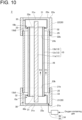
- the cell 2 includes the electrode device 10 with the negative electrode 11a as the first electrode 11, a discharging positive electrode 12c as the second electrode 12, and the charging positive electrode 13b as the third electrode 13.
- An inner peripheral surface of the discharging positive electrode 12c, that is, a surface facing the negative electrode 11a is provided with the separation membrane 26.
- Each of the first chamber section 21 and the second chamber section 22 is internally provided with the separation member 30 for separating the flow of the electrolyte solution in the chamber 20 into the first flow F1 flowing through a flow path between an outer peripheral surface of the discharging positive electrode 12c and the inner peripheral surface of the charging positive electrode 13b, and the second flow F2 flowing through a flow path between the outer peripheral surface of the negative electrode 11a and the inner peripheral surface of the discharging positive electrode 12c.
- the separation member 30 has the tubular shape in which the end faces 31, 32 are disposed at the both ends in the axial direction of the cell 2 when disposed inside the first chamber section 21 and the second chamber section 22, and the openings 31a, 32a are respectively formed in the end faces 31, 32.
- the discharging positive electrode 12c is inserted into the one opening 32a, and the seal member 33 such as the O-ring is disposed between the inner peripheral edge of the opening 32a and the outer peripheral surface of the discharging positive electrode 12c.
- the other opening 31a faces the first opening 23a or the third opening 24a.
- the oxygen-containing gas supply device 34 is provided to supply the oxygen-containing gas such as air to the electrolyte solution of the first flow F1 outside the separation member 30 disposed in, among the first chamber section 21 and the second chamber section 22, the first chamber section 21 located upstream in the flow direction of the electrolyte solution flowing in the cell 2.
- the configuration of the oxygen-containing gas supply device 34 in Embodiment 5 is the same as in Embodiment 3. Other configurations are the same as those in Embodiment 1.
- Embodiment 3 applies to the operation of the metal-air battery system 1 according to Embodiment 5, except that the first flow F1 is the flow flowing through the flow path between the outer peripheral surface of the discharging positive electrode 12c and the inner peripheral surface of the charging positive electrode 13b and the second flow F2 is the flow flowing through the flow path between the outer peripheral surface of the negative electrode 11a and the inner peripheral surface of the discharging positive electrode 12c. Therefore, Embodiment 5 can also obtain the same technical effect as the technical effect obtained in Embodiment 3.
- Embodiment 5 since the negative electrode 11a, the discharging positive electrode 12c, and the charging positive electrode 13b are disposed such that their cross sections are concentric, the same technical effect as the technical effect obtain in Embodiment 1 can be obtained.
- Embodiment 5 since the first electrode 11 is the negative electrode 11a and the third electrode 13 is the charging positive electrode 13b, a distance between the negative electrode 11a and the charging positive electrode 13b is large compared to Embodiments 1 to 4. Therefore, in Embodiment 5, an internal short circuit is less likely to occur when the metal-air battery system 1 is charged, compared to Embodiments 1 to 4.
- a measuring instrument is provided to measure a potential difference between the negative electrode 11a and the discharging positive electrode 12c, and this potential difference is monitored during charging, making it possible to detect that internal short circuit has occurred between the negative electrode 11a and the discharging positive electrode 12c. If the internal short circuit between the negative electrode 11a and the discharging positive electrode 12c is detected, the internal short circuit can be eliminated by discharging using the negative electrode 11a and the charging positive electrode 13b.
- Embodiment 5 since the separation membrane 26 is disposed on the inner peripheral surface of the discharging positive electrode 12c, it is possible to prevent oxygen contained in the electrolyte solution of the first flow F1 from moving to the electrolyte solution of the second flow F2 via the discharging positive electrode 12c. Whereby, it is possible to suppress formation of a high-resistivity layer of zinc oxide in the electrolyte solution of the second flow F2.
- the separation membrane 26 is also disposed on the inner peripheral surface of the charging positive electrode 13b, making it possible to suppress leakage of the electrolyte solution from the cell 2 via the charging positive electrode 13b.
- the metal-air battery system according to Embodiment 6 is obtained by modifying the configuration of the electrode device 10 with respect to Embodiment 5.
- the same constituent elements as those in Embodiment 5 are associated with the same reference signs and not described again in detail.
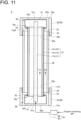
- the cell 2 includes the electrode device 10 with the charging positive electrode 11b as the first electrode 11, the discharging positive electrode 12c as the second electrode 12, and the negative electrode 13c as the third electrode 13.
- An outer peripheral surface of the discharging positive electrode 12c, that is, a surface facing the negative electrode 13c is provided with the separation membrane 26.
- the three-layer structure of the discharging positive electrode 12c is the same as the three-layer structure of the discharging positive electrode 11c (see FIG. 5 ) of Embodiments 3 and 4.
- Each of the first chamber section 21 and the second chamber section 22 is internally provided with the separation member 30 for separating the flow of the electrolyte solution in the chamber 20 into the first flow F1 flowing through a flow path between the outer peripheral surface of the charging positive electrode 11b and the inner peripheral surface of the discharging positive electrode 12c, and the second flow F2 flowing through a flow path between the outer peripheral surface of the discharging positive electrode 12c and the inner peripheral surface of the negative electrode 13c.
- the oxygen-containing gas supply device 34 is provided to supply the oxygen-containing gas such as air to the electrolyte solution of the first flow F1 inside the separation member 30 disposed in, among the first chamber section 21 and the second chamber section 22, the first chamber section 21 located upstream in the flow direction of the electrolyte solution flowing in the cell 2.
- Other configurations are the same as those in Embodiment 5.
- Embodiment 5 the description of the operation of Embodiment 3 applies to the operation of the metal-air battery system 1 according to Embodiment 6, except that the first flow F1 is the flow flowing through the flow path the outer peripheral surface of the charging positive electrode 11b and the inner peripheral surface of the discharging positive electrode 12c and the second flow F2 is the flow flowing through the flow path between the outer peripheral surface of the discharging positive electrode 12c and the inner peripheral surface of the negative electrode 13c. Therefore, Embodiment 6 can also obtain the same technical effect as the technical effect obtained in Embodiment 3.
- Embodiment 6 since the charging positive electrode 11b, the discharging positive electrode 12c, and the negative electrode 13c are disposed such that their cross sections are concentric, the same technical effect as the technical effect obtain in Embodiment 1 can be obtained.
- Embodiment 6 since the first electrode 11 is the charging positive electrode 11b and the third electrode 13 is the negative electrode 13c, a distance between the charging positive electrode 11b and the negative electrode 13c is large compared to Embodiments 1 to 4. Therefore, in Embodiment 6, an internal short circuit is less likely to occur when the metal-air battery system 1 is charged, compared to Embodiments 1 to 4.
- Embodiment 6 since the third electrode 13 arranged on the outermost side in the electrode device 10 is the negative electrode 13c, the area of the negative electrode relatively increases compared to a case where the first electrode 11 or the second electrode 12 is the negative electrode. Therefore, the amount of zinc deposited on the negative electrode 13c in Embodiment 6 increases compared to Embodiment 1, making it possible to increase the electricity storage capacity compared to Embodiment 1.
- a measuring instrument is provided to measure a potential difference between the negative electrode 13c and the discharging positive electrode 12c, and this potential difference is monitored during charging, making it possible to detect that internal short circuit has occurred between the negative electrode 13c and the discharging positive electrode 12c. If the internal short circuit between the negative electrode 13c and the discharging positive electrode 12c is detected, the internal short circuit can be eliminated by discharging using the negative electrode 13c and the charging positive electrode 11b.
- Embodiment 6 since the separation membrane 26 is disposed on the outer peripheral surface of the discharging positive electrode 12c, it is possible to prevent oxygen contained in the electrolyte solution of the first flow F1 from moving to the electrolyte solution of the second flow F2 via the discharging positive electrode 12c. Whereby, it is possible to suppress formation of a high-resistivity layer of zinc oxide in the electrolyte solution of the second flow F2.
- the difference in electrode area between the inner side and the outer side can be obtained by arranging the electrodes such that their cross sections are concentric, it is possible to reduce the current density during operation of the electrodes arranged on the outer side compared to that of the central electrode.
- the resistance of the system can be reduced by utilizing this effect to arrange, on the outer side, the electrodes requiring a reduction in resistance loss, making it possible to efficiently charge/discharge.
- the electrolyte solution is supplied in circulation to the cell, electricity can be stored.
- a metal-air battery system is the metal-air battery system of [1], further including a switching device (7) for switching such that the negative electrode (11a, 12b, 13c) is electrically connected to either the charging positive electrode (11b, 12a, 13b) or the discharging positive electrode (11c, 12c, 13a).
- the switching device (7) includes: a first switch (7c) for electrically opening and closing between the discharging positive electrode (11c, 12c, 13a) and the negative electrode (11a, 12b, 13c); and a second switch (7d) for electrically opening and closing between the negative electrode (11a, 12b, 13c) and the charging positive electrode (11b, 12a, 13b).
- a metal-air battery system is the metal-air battery system of [2], wherein the switching device (7) includes a first diode (7a) for flowing a current in a direction from the discharging positive electrode (11c, 12c, 13a) to the negative electrode (11a, 12b, 13c).
- a metal-air battery system is the metal-air battery system of [3], wherein the switching device (7) further includes a second diode (7ba) for flowing the current in a direction from the negative electrode (11a, 12b, 13c) to the charging positive electrode (11b, 12a, 13b).
- the switching device (7) further includes a second diode (7ba) for flowing the current in a direction from the negative electrode (11a, 12b, 13c) to the charging positive electrode (11b, 12a, 13b).
- a metal-air battery system is the metal-air battery system of any of [1] to [4], wherein the electrode device (10) has a shape extending in an axial direction, and includes a first end portion (10a) which is one end portion in the axial direction and a second end portion (10b) which is another end portion in the axial direction, wherein the chamber (20) includes: a first chamber section (21) disposed so as to internally house at least one end portion (13d1) of the third electrode (13) on a side of the first end portion (10a) of the electrode device (10); and a second chamber section (22) disposed so as to internally house at least another end portion (13d2) of the third electrode (13) on a side of the second end portion (10b) of the electrode device (10), wherein the first chamber section (21) has a first end face (21a) and a second end face (21b) located away from each other in the axial direction, and the first end face (21a) and the second end face (21b) are respectively formed with
- a metal-air battery system is the metal-air battery system of [5], wherein the third electrode (13) is the discharging positive electrode (13a).
- a metal-air battery system is the metal-air battery system of [5], wherein the first electrode (11) is the discharging positive electrode (11c) having a tubular shape, wherein each of the first chamber section (21) and the second chamber section (22) is internally provided with a separation member (30) for separating a flow of the electrolyte solution in the chamber (20) into a first flow (F1) flowing inside the discharging positive electrode (11c) and a second flow (F2) flowing outside the discharging positive electrode (11c), and wherein the metal-air battery system further includes an oxygen-containing gas supply device (34) for supplying an oxygen-containing gas to the electrolyte solution of the first flow (F1).
- a metal-air battery system is the metal-air battery system of [5], wherein the first electrode (11) is the discharging positive electrode (11c) having a tubular shape, wherein only the discharging positive electrode (11c) of the electrode device (10) is inserted into the first opening (23a) and the third opening (24a), and wherein an oxygen-containing fluid supply device (37) is provided to flow, inside the discharging positive electrode (11c), a fluid containing oxygen.
- a metal-air battery system is the metal-air battery system of [7] or [8], wherein the second electrode (12) is the charging positive electrode (12a), and the third electrode (13) is the negative electrode (13c).
- the area of the negative electrode relatively increases compared to a case where the first electrode or the second electrode is the negative electrode. Therefore, the amount of metal deposited on the negative electrode increases, making it possible to increase the electricity storage capacity.
- a metal-air battery system is the metal-air battery system of [7] or [8], wherein the second electrode (12) is the negative electrode (12b), and the third electrode (13) is the charging positive electrode (13b).
- an internal short circuit between the negative electrode and the charging positive electrode can be detected in advance by monitoring the voltage between the negative electrode and the discharging positive electrode.
- a metal-air battery system is the metal-air battery system of [5], wherein the second electrode (12) is the discharging positive electrode (12c), wherein each of the first chamber section (21) and the second chamber section (22) is internally provided with a separation member (30) for separating a flow of the electrolyte solution in the chamber (20) into a first flow (F1) flowing between the charging positive electrode (11b, 13b) and the discharging positive electrode (12c), and a second flow (F2) flowing between the discharging positive electrode (12c) and the negative electrode (11a, 13c), and wherein the metal-air battery system (1) further includes an oxygen-containing gas supply device (34) for supplying an oxygen-containing gas to the electrolyte solution of the first flow (F1).
- the distance between the negative electrode and the charging positive electrode increases compared to the configuration where the negative electrode and the charging positive electrode are adjacent to each other, making it unlikely to cause an internal short circuit between the negative electrode and the charging positive electrode.
- the internal short circuit between the negative electrode and the charging positive electrode can be detected in advance by monitoring the voltage between the negative electrode and the discharging positive electrode.
- a metal-air battery system is the metal-air battery system of [11], wherein the first electrode (11) is the charging positive electrode (11b), and the third electrode (13) is the negative electrode (13c).
- the area of the negative electrode relatively increases compared to a case where the first electrode or the second electrode is the negative electrode. Therefore, the amount of metal deposited on the negative electrode increases, making it possible to increase the electricity storage capacity.
- a metal-air battery system is the metal-air battery system of [11], wherein the first electrode (11) is the negative electrode (11a), and the third electrode (13) is the charging positive electrode (13b).
- the difference in electrode area between the inner side and the outer side can be obtained by arranging electrodes such that their cross sections are concentric, it is possible to reduce the current density during operation of the electrodes arranged on the outer side compared to that of the central electrode.
- the resistance of the system can be reduced by utilizing this effect to arrange, on the outer side, the electrodes requiring a reduction in resistance loss, making it possible to efficiently charge/discharge. Further, since the electrolyte solution is supplied in circulation to the cell, electricity can be stored.
- a metal-air battery system is the metal-air battery system of any of [1] to [13], wherein the discharging positive electrode (11c, 12c, 13a) includes a separation membrane (26) on a surface facing the negative electrode (11a, 12b, 13c).
Landscapes
- Chemical & Material Sciences (AREA)
- Chemical Kinetics & Catalysis (AREA)
- Electrochemistry (AREA)
- General Chemical & Material Sciences (AREA)
- Engineering & Computer Science (AREA)
- Manufacturing & Machinery (AREA)
- Life Sciences & Earth Sciences (AREA)
- Sustainable Development (AREA)
- Sustainable Energy (AREA)
- Hybrid Cells (AREA)
Abstract
Description
- The present disclosure relates to a metal-air battery system.
- This application claims the priority of
Japanese Patent Application No. 2021-110540 filed on July 2, 2021 - A metal-air battery system is known which uses metal as a negative electrode active material and oxygen (air) as a positive electrode active material. Patent Document 1 describes a cylindrical three-electrode metal-air battery system in which a cylindrical fuel electrode, auxiliary electrode, and air electrode immersed in an electrolyte solution are concentrically arranged. This metal-air battery system can be used as a secondary battery in which the fuel electrode and the auxiliary electrode are used to charge and the fuel electrode and the air electrode are used to discharge, and can be used as a fuel cell in which zinc pellets are introduced to the auxiliary electrode having a holding structure and the auxiliary electrode and the air electrode are used to generate electricity.
- Patent Document 1:
JP2015-170400A - If electricity needs to be stored in the metal-air battery system, the electrolyte solution is stored in a tank, and the electrolyte solution is supplied in circulation by a pump. However, in the metal-air battery system of Patent Document 1, the electrolyte solution is not configured to be supplied in circulation, and if the electrolyte solution is configured to be supplied in circulation, the zinc pellets introduced to the auxiliary electrode may flow away along with the electrolyte solution. Therefore, it is not envisaged that the metal-air battery system of Patent Document 1 would be modified such that the electrolyte solution is supplied in circulation, and further such modification cannot be made easily.
- In view of the above, an object of at least one embodiment of the present disclosure is to provide a metal-air battery system that can store electricity, and charge and discharge efficiently.
- In order to achieve the above-described object, a metal-air battery system according to the present disclosure is a metal-air battery system that includes a cell including: a chamber; and an electrode device housed in the chamber. The electrode device includes: a first electrode; a tubular second electrode disposed so as to surround the first electrode on a radially outer side of the first electrode; and a tubular third electrode disposed so as to surround the second electrode on a radially outer side of the second electrode, and is configured such that an electrolyte solution flows at least between an outer peripheral surface of the first electrode and an inner peripheral surface of the third electrode. A combination of the first electrode, the second electrode, and the third electrode is a combination of a negative electrode containing metal, a charging positive electrode, and a discharging positive electrode.
- According to the metal-air battery system of the present disclosure, since a difference in electrode area between the inner side and the outer side can be obtained by arranging electrodes such that their cross sections are concentric, it is possible to reduce a current density during operation of the electrodes arranged on the outer side compared to that of the central electrode. The resistance of the system can be reduced by utilizing this effect to arrange, on the outer side, the electrodes requiring a reduction in resistance loss, making it possible to efficiently charge/discharge. Further, since the electrolyte solution is supplied in circulation to the cell, electricity can be stored.
-
-
FIG. 1 is a schematic configuration diagram of a metal-air battery system according to Embodiment 1 of the present disclosure. -
FIG. 2 is a schematic configuration diagram showing a modified example of the metal-air battery system according to Embodiment 1 of the present disclosure. -
FIG. 3 is a cross-sectional schematic diagram showing the configuration of a three-electrode cell of the metal-air battery system according to Embodiment 1 of the present disclosure. -
FIG. 4 is a cross-sectional schematic diagram showing the configuration of the three-electrode cell of the metal-air battery system according toEmbodiment 2 of the present disclosure. -
FIG. 5 is a cross-sectional schematic diagram showing the configuration of the three-electrode cell of the metal-air battery system according toEmbodiment 3 of the present disclosure. -
FIG. 6 is a cross-sectional schematic diagram showing the configuration of the three-electrode cell of a modified example of the metal-air battery system according toEmbodiment 3 of the present disclosure. -
FIG. 7 is a schematic configuration diagram showing part of another modified example of the metal-air battery system according toEmbodiment 3 of the present disclosure. -
FIG. 8 is a cross-sectional schematic diagram showing the configuration of the three-electrode cell of the metal-air battery system according toEmbodiment 4 of the present disclosure. -
FIG. 9 is a cross-sectional schematic diagram showing the configuration of the three-electrode cell of a modified example of the metal-air battery system according toEmbodiment 4 of the present disclosure. -
FIG. 10 is a cross-sectional schematic diagram showing the configuration of the three-electrode cell of the metal-air battery system according toEmbodiment 5 of the present disclosure. -
FIG. 11 is a cross-sectional schematic diagram showing the configuration of the three-electrode cell of the metal-air battery system according toEmbodiment 6 of the present disclosure. - Hereinafter, a metal-air battery system according to embodiments of the present disclosure will be described with reference to the drawings. The embodiment to be described below indicates one aspect of the present disclosure, does not intend to limit the disclosure, and can optionally be modified within a range of a technical idea of the present disclosure.
- As shown in
FIG. 1 , a metal-air battery system 1 according to Embodiment 1 of the present disclosure includes a cylindrical three-electrode cell 2. Both ends of acirculation line 3 for an electrolyte solution are connected to thecell 2 in order to flow the electrolyte solution inside thecell 2. Thecirculation line 3 includes anelectrolytic tank 4 for storing the electrolyte solution, and apump 5. - As the electrolyte solution, it is possible to use either an aqueous electrolyte solution in which an electrolyte is dissolved in water or a non-aqueous electrolyte in which an electrolyte is dissolved in a non-aqueous solution such as an organic solvent. As the aqueous electrolyte solution, it is possible to use, for example, an aqueous solution in which a hydroxide such as potassium, sodium, lithium, barium, or magnesium, a chloride, a phosphate, a borate, a sulfate, etc. is used as an electrolyte. That is, any indicator salt for imparting electrical conductivity of the aqueous solution can be used as the electrolyte. As the non-aqueous electrolyte solution, it is possible to use, for example, a solution obtained by dissolving an indicator salt containing an alkali metal etc. in a liquid such as a cyclic or chain carbonate, a cyclic or chain ester, a cyclic or chain ether, a sulfone compound, an ionic liquid, etc.
- The
cell 2 includes anelectrode device 10 that has a shape extending in the axial direction, and includes afirst electrode 11, a tubularsecond electrode 12 disposed so as to surround thefirst electrode 11 on a radially outer side of thefirst electrode 11, and a tubularthird electrode 13 disposed so as to surround the second electrode12 on a radially outer side of the second electrode. Herein, "surround" means a configuration in which at least a part of thefirst electrode 11 in a length direction and at least a part of thesecond electrode 12 in a length direction are housed inside thesecond electrode 12 and thethird electrode 13, respectively. That is, thefirst electrode 11, thesecond electrode 12, and thethird electrode 13 are disposed such that their cross sections perpendicular to the axial direction have a concentric shape (a concentric circular shape if these electrodes are cylindrical). In Embodiment 1, thefirst electrode 11 is anegative electrode 11a, thesecond electrode 12 is a chargingpositive electrode 12a used together with thenegative electrode 11a during charging of the metal-air battery system 1, and thethird electrode 13 is a dischargingpositive electrode 13a used together with thenegative electrode 11a during discharging of the metal-air battery system 1. - The
negative electrode 11a may be a tubular electrode made of metal such as zinc, or may be an electrode in which a surface of a tubular body made of other metal such as stainless steel or aluminum is plated with zinc. In the latter case, it is only necessary that at least an outer surface, of the surface of thenegative electrode 11a, facing the chargingpositive electrode 12a is plated with zinc. The metal contained in thenegative electrode 11a is not limited to zinc. Iron, aluminum, lithium, sodium, potassium, copper, magnesium, etc., or alloys thereof can be used depending on the type of electrolyte solution (for example, a difference in aqueous electrolyte solution/non-aqueous electrolyte solution). A tubular electrode made of a non-oxidizing porous metal material such as nickel, nickel alloy, or stainless steel in a mesh shape can be used as the chargingpositive electrode 12a. - As the discharging
positive electrode 13a, it is possible to use, for example, an electrode having a three-layer structure including a porous outermost layer in which oxygen can diffuse, a porous intermediate layer formed of metal such as nickel, and an innermost layer in which an oxygen reduction catalyst is supported on a conductive material such as carbon. As the oxygen reduction catalyst, a catalyst mainly containing platinum as an active component (for example, platinum-supported carbon) can be used under an acidic liquid environment. Also, under an alkaline liquid environment, a catalyst can be used, which contains 3d transition metal such as iron, manganese, nickel, or cobalt, or its oxide as an active component. In addition, a catalyst containing ruthenium, silver, gold, or iridium as an active component can also be used under both the acidic liquid environment and the alkaline liquid environment. Further, a catalyst can also be used, which contains an organometallic complex, a carbon fiber (for example, a carbon nanotube), a nitrogen carbide, etc. as an active component. Moreover, according to this configuration, since electrode areas of the chargingpositive electrode 12a and the dischargingpositive electrode 13a can be greater than that of thenegative electrode 11a, a current density during charging/discharging can be lower than that of thenegative electrode 11a. Whereby, it is possible to expect an effect of being able to relatively reduce a loss due to resistance of the chargingpositive electrode 12a and the dischargingpositive electrode 13a. - The metal-air battery system 1 can further include a
switching device 7. Thenegative electrode 11a is electrically connected to an AC/DC converter 6, and the chargingpositive electrode 12a and the dischargingpositive electrode 13a are connected to the AC/DC converter 6 via theswitching device 7 which is switchable such that either one of the chargingpositive electrode 12a or the dischargingpositive electrode 13a energizes the AC/DC converter 6, that is, thenegative electrode 11a is electrically connected to either one of the chargingpositive electrode 12a or the dischargingpositive electrode 13a. The AC/DC converter 6 can electrically be connected to a load 8 and an AC power source 9. The AC/DC converter 6 is not required if a DC power source is used in place of the AC power source 9 and the load 8 operates on DC current. - Although the configuration of the
switching device 7 is not particularly limited, for example, theswitching device 7 may be composed of afirst switch 7c for electrically opening and closing between the dischargingpositive electrode 13a and thenegative electrode 11a, and asecond switch 7d for electrically opening and closing between thenegative electrode 11a and the chargingpositive electrode 12a (hereinafter, referred to as the "switch-type switching device 7"). Thefirst switch 7c and thesecond switch 7d are not limited to mechanical switches, and may be semiconductor switches. Further, as shown inFIG. 2 , theswitching device 7 may be composed of afirst diode 7a for flowing a current in a direction from the dischargingpositive electrode 13a to thenegative electrode 11a, and asecond diode 7b for flowing a current in a direction from thenegative electrode 11a to the chargingpositive electrode 12a (hereinafter, referred to as the "diode-type switching device 7"). The diode-type switching device 7 is superior in terms of durability and cost compared to the switch-type switching device 7 composed of the mechanical switches, and is superior in terms of cost compared to the switch-type switching device 7 composed of the semiconductor switches. Since the chargingpositive electrode 12a does not undergo a discharge reaction in a state where the chargingpositive electrode 12a is immersed in the electrolyte solution, thesecond diode 7b may not be provided (theswitching device 7 is composed only of thefirst diode 7a). Also, thefirst diode 7a may not be provided, either (that is, a configuration in which theswitching device 7 is not provided) if it is not necessary to consider the reaction at the dischargingpositive electrode 13a during charging. - As shown in
FIG. 3 , thecell 2 includes achamber 20 for housing theelectrode device 10. Thechamber 20 includes afirst chamber section 21 provided so as to internally house at least one end portion 13d1 of thethird electrode 13 on a side of afirst end portion 10a which is one end portion of theelectrode device 10, and asecond chamber section 22 provided so as to internally house at least another end portion 13d2 of thethird electrode 13 on a side of asecond end portion 10b which is another end portion of theelectrode device 10. - The
first chamber section 21 has afirst end face 21a and asecond end face 21b located away from each other in the axial direction of thecell 2, and thefirst end face 21a and thesecond end face 21b are respectively formed with afirst opening 23a and asecond opening 23b. Thesecond chamber section 22 has athird end face 22a and afourth end face 22b located away from each other in the axial direction of thecell 2, and thethird end face 22a and thefourth end face 22b are respectively formed with athird opening 24a and afourth opening 24b. - The
first electrode 11, thesecond electrode 12, and thethird electrode 13 are respectively inserted into thesecond opening 23b and thefourth opening 24b, and aseal member 25 for sealing between an outer peripheral surface of thethird electrode 13 and respective inner peripheral surfaces of thefirst chamber section 21 and thesecond chamber section 22 is disposed therebetween. Theseal member 25 can suppress leakage of the electrolyte solution from thechamber 20 between thefirst opening 23a and thethird opening 24a. Theseal member 25 may be an adhesive agent, a heat-shrinkable tube, a heat seal, a resin weld, or the like. - The inner peripheral surface of the discharging
positive electrode 13a, that is, the surface facing thenegative electrode 11a is provided with aseparation membrane 26. As theseparation membrane 26, it is possible to use, for example, an anion exchange membrane, or a microporous membrane formed from polymer, solid oxide, or the like. Although the configuration of the anion exchange membrane is not particularly limited, it is preferable to use a high-performance membrane with high ion conductivity and strength. Also, the configuration of the microporous membrane is not particularly limited, either and commercially available membranes for various purposes can be used. Although it is preferable to use a microporous membrane suitable for an aqueous solution system if the aqueous electrolyte solution is used, any resin-made microporous membrane can be used as long as hydrophilic treatment is applied to a surface, for example, modifying the surface with a hydrophilic group, adding a surfactant to the surface, or combining the surface with oxide particles. - Next, the operation of the metal-air battery system 1 will be described with reference to
FIGs. 1 to 3 . First, the operation in which current flows through the load 8 due to the discharge of the metal-air battery system 1 will be described. Thepump 5 is started in a state where theswitching device 7 is operated to electrically connect thenegative electrode 11a to the dischargingpositive electrode 13a, and the electrolyte solution is supplied from theelectrolytic tank 4 to thecell 2 via thecirculation line 3. The electrolyte solution circulates through thecirculation line 3 by returning to theelectrolytic tank 4 via thecirculation line 3 after passing through thecell 2. - In the
cell 2, the electrolyte solution having flowed into thefirst chamber section 21 via thefirst opening 23a flows into, via thefirst end portion 10a of theelectrode device 10, flow paths formed between the outer peripheral surface of thenegative electrode 11a and the inner peripheral surface of the dischargingpositive electrode 13a, that is, a flow path formed between the outer peripheral surface of thenegative electrode 11a and the inner peripheral surface of the chargingpositive electrode 12a and a flow path formed between the outer peripheral surface of the chargingpositive electrode 12a and the inner peripheral surface of the dischargingpositive electrode 13a, and flows through these flow paths. The electrolyte solution having flowed through these flow paths flows out from these flow paths to thesecond chamber section 22 via thesecond end portion 10b of theelectrode device 10, and flows out from thesecond chamber section 22 via thethird opening 24a. - While the electrolyte solution thus flows in the
cell 2, the following reaction occurs in thenegative electrode 11a and the dischargingpositive electrode 13a. In thenegative electrode 11a, metal contained in thenegative electrode 11a, such as zinc, reacts with hydroxide ions in the electrolyte solution to generate zincate ions, and electrons are emitted to thenegative electrode 11a and flow to the dischargingpositive electrode 13a. In the dischargingpositive electrode 13a, oxygen contained in air outside thecell 2 diffuses through the outermost layer and the intermediate layer, and hydroxide ions are produced by reactions between the air, water in the electrolyte solution, and the electrons flowing to the dischargingpositive electrode 13a due to the oxygen reduction catalyst in the innermost layer. The produced hydroxide ions are used in the above-described reaction at thenegative electrode 11a. - If the anion exchange membrane which is the
separation membrane 26 is provided on the inner peripheral surface of the dischargingpositive electrode 13a, that is, the innermost layer (a layer where the oxygen reduction catalyst is supported on the conductive material) of the dischargingpositive electrode 13a, oxygen molecules react at a reaction interface (three-phase interface) where the oxygen reduction catalyst/conductive material/ionic conductor contact, producing hydroxide ions. The produced hydroxide ions move into the electrolyte solution through the ionic conductor. Whereby, the reaction interface by ionomer contact with the oxygen reduction catalyst is extended and the resistance is reduced. In addition, if theseparation membrane 26 is provided on the inner peripheral surface of the dischargingpositive electrode 13a, it is possible to suppress leakage of the electrolyte solution to the outside of thecell 2 via the dischargingpositive electrode 13a or clogging of the intermediate layer and the outermost layer of the dischargingpositive electrode 13a. Further, precipitation of carbonate from the electrolyte solution and clogging of the intermediate layer and the outermost layer of the dischargingpositive electrode 13a can be suppressed by suppressing mixing of carbon dioxide contained in the air into the electrolyte solution. Therefore, it is possible to reduce an overvoltage loss of the reaction in the dischargingpositive electrode 13a, and it is possible to suppress alteration, deterioration, or leakage of the electrolyte solution. - As electrons flow from the
negative electrode 11a to the dischargingpositive electrode 13a by such operation, DC current flows from the dischargingpositive electrode 13a to thenegative electrode 11a. The AC/DC converter 6 converts this DC current into AC current and supplies AC current to the load 8. - Next, the charging operation of the metal-air battery system 1 will be described. The electrolyte solution is circulated in a state where the
switching device 7 is operated to electrically connect thenegative electrode 11a to the chargingpositive electrode 12a. The AC current from the AC power source 9 is converted into DC current by the AC/DC converter 6, and the DC current flows to the chargingpositive electrode 12a. That is, electrons flow to thenegative electrode 11a. At thenegative electrode 11a, zinc ions in the electrolyte solution receive electrons, thereby depositing zinc on thenegative electrode 11a, and the metal-air battery system 1 is charged. - No problem occurs if zinc is uniformly deposited on the surface of the
negative electrode 11a during such charging, but in reality, a dendrite partially extending like needles may be generated. If the dendrite is generated and grows, the dendrite may connect thenegative electrode 11a and the chargingpositive electrode 12a. Then, an internal short circuit occurs and the voltage of the battery becomes 0 V, making it impossible to charge the battery. - In the event that such internal short circuit occurs, if the
switching device 7 is provided, thenegative electrode 11a is electrically connected to the dischargingpositive electrode 13a by closing thefirst switch 7c and opening thesecond switch 7d, thereby switching from the charging state to the discharging state. Even if thenegative electrode 11a and the chargingpositive electrode 12a are internally short-circuited by the dendrite, thenegative electrode 11a and the chargingpositive electrode 12a are electrically separated, allowing for discharge using thenegative electrode 11a and the dischargingpositive electrode 13a. During discharging, zinc is eluted as zinc ions from thenegative electrode 11a into the electrolyte solution, eliminating the internal short circuit. - Since the difference in electrode area between the inner side and the outer side can be obtained by arranging the
negative electrode 11a, the chargingpositive electrode 12a, and the dischargingpositive electrode 13a such that their cross sections are concentric, it is possible to reduce the current density during operation of the chargingpositive electrode 12a and the dischargingpositive electrode 13a arranged on the outer side compared to that of the centralnegative electrode 11a. The resistance of the system can be reduced by utilizing this effect to arrange the chargingpositive electrode 12a and the dischargingpositive electrode 13a, which require a reduction in resistance loss, on the outer side, making it possible to efficiently charge/discharge. Further, since the electrolyte solution is supplied in circulation to the cell, electricity can be stored. - In addition, since the switch-
type switching device 7 is provided, thenegative electrode 11a and the chargingpositive electrode 12a are used to charge and thenegative electrode 11a and the dischargingpositive electrode 13a are used to discharge, making it possible to discharge even if internal short circuit occurs during charging. Whereby, it is possible to charge/discharge without any trouble. Further, since the electrolyte solution is supplied in circulation to thecell 2, electricity can be stored. On the other hand, since either the switch-type or diode-type switching device 7 is provided, it is possible to reduce the risk of opposite reactions occurring at the positive electrode during charging and discharging, and improvements in efficiency and lifetime can be expected. - In Embodiment 1, although the
negative electrode 11a does not have a tubular shape, thenegative electrode 11a may also have the tubular shape just like the chargingpositive electrode 12a and the dischargingpositive electrode 13a. In this case, since the electrolyte solution also flows into thenegative electrode 11a, the configuration is preferable in which the inner peripheral surface of thenegative electrode 11a also contains zinc. - Next, the metal-air battery system according to
Embodiment 2 will be described. The metal-air battery system according toEmbodiment 2 is obtained by modifying the configuration of theelectrode device 10 with respect to Embodiment 1. InEmbodiment 2, the same constituent elements as those in Embodiment 1 are associated with the same reference signs and not described again in detail. - As shown in
FIG. 4 , inEmbodiment 2 of the present disclosure, thecell 2 includes theelectrode device 10 with a chargingpositive electrode 11b as thefirst electrode 11, a negative electrode 12b as thesecond electrode 12, and the dischargingpositive electrode 13a as thethird electrode 13. The negative electrode 12b has a tubular shape, and the negative electrode 12b is configured to contain zinc not only on its outer peripheral surface but also on its inner peripheral surface. Further, as in Embodiment 1, an electrode having a tubular shape manufactured in a mesh shape may be used as the chargingpositive electrode 11b. InEmbodiment 2, however, the chargingpositive electrode 11b will be described as an electrode having a non-mesh non-tubular shape, that is, a bar shape. Other configurations are the same as those in Embodiment 1. - The operation in
Embodiment 2 is the same as that in Embodiment 1. That is, in the metal-air battery system 1 according toEmbodiment 2 as well, the negative electrode 12b and the chargingpositive electrode 11b are used to charge and the negative electrode 12b and the dischargingpositive electrode 13a are used to discharge, making it possible to discharge even if internal short circuit occurs during charging. InEmbodiment 2 as well, since the chargingpositive electrode 11b, the negative electrode 12b, and the dischargingpositive electrode 13a are disposed such that their cross sections are concentric, the same technical effect as in Embodiment 1 can be obtained. - In
Embodiment 2, a measuring instrument is provided to measure a potential difference between the negative electrode 12b and the dischargingpositive electrode 13a, and this potential difference is monitored during charging, making it possible to detect that internal short circuit has occurred between the negative electrode 12b and the dischargingpositive electrode 13a. If the internal short circuit between the negative electrode 12b and the dischargingpositive electrode 13a is detected, the internal short circuit can be eliminated by discharging using the negative electrode 12b and the chargingpositive electrode 11b. - Next, the metal-air battery system according to
Embodiment 3 will be described. The metal-air battery system according toEmbodiment 3 is obtained by modifying the configuration of theelectrode device 10 with respect to Embodiment 1. InEmbodiment 3, the same constituent elements as those in Embodiment 1 are associated with the same reference signs and not described again in detail. - As shown in
FIG. 5 , inEmbodiment 3 of the present disclosure, thecell 2 includes theelectrode device 10 with a dischargingpositive electrode 11c as thefirst electrode 11, the chargingpositive electrode 12a as thesecond electrode 12, and anegative electrode 13c as thethird electrode 13. All of the dischargingpositive electrode 11c, the chargingpositive electrode 12a, and thenegative electrode 13c have a tubular shape. An outer peripheral surface of the dischargingpositive electrode 11c, that is, a surface facing thenegative electrode 13c is provided with theseparation membrane 26. However, in Embodiment 3 (the same also applies toEmbodiment 4 described later), a three-layer structure of the dischargingpositive electrode 11c is different from that of the dischargingpositive electrode 13a (seeFIG. 2 ) ofEmbodiments 1 and 2, and the layer where the oxygen reduction catalyst is supported on the conductive material such as carbon is the outermost layer on the outer peripheral surface side and the porous layer in which oxygen can diffuse is the innermost layer on the inner peripheral surface side. - Each of the
first chamber section 21 and thesecond chamber section 22 is internally provided with aseparation member 30 for separating the flow of the electrolyte solution in thechamber 20 into a first flow F1 flowing inside the dischargingpositive electrode 11c and a second flow F2 flowing outside the dischargingpositive electrode 11c. Theseparation member 30 has a tubular shape in which end faces 31, 32 are disposed at both ends in the axial direction of thecell 2 when disposed inside thefirst chamber section 21 and thesecond chamber section 22, andopenings positive electrode 11c is inserted into the oneopening 32a, and aseal member 33 such as an O-ring is disposed between an inner peripheral edge of the opening 31b and an outer peripheral surface of the dischargingpositive electrode 11c. Theother opening 31a faces thefirst opening 23a or thethird opening 24a. - An oxygen-containing
gas supply device 34 is provided to supply an oxygen-containing gas such as air to the electrolyte solution of the first flow F1 inside theseparation member 30 disposed in, among thefirst chamber section 21 and thesecond chamber section 22, thefirst chamber section 21 located upstream in the flow direction of the electrolyte solution flowing in thecell 2. As the oxygen-containinggas supply device 34, it is possible to use, for example, a bubbling device that includes an oxygen-containinggas supply line 35 having one end located inside theseparation member 30 and another end opening to the outside of thecell 2 or connected to an oxygen-containing gas cylinder or the like, and acompressor 36 disposed on the oxygen-containinggas supply line 35. Other configurations are the same as those in Embodiment 1. - Next, the operation of the metal-air battery system 1 according to
Embodiment 3 will be described, focusing on differences from the operation of the metal-air battery system 1 according to Embodiment 1. When the metal-air battery system 1 is discharged, in thecell 2, the electrolyte solution having flowed into thefirst chamber section 21 via thefirst opening 23a is divided into the first flow F1 which is a flow of the electrolyte solution entering the inside of theseparation member 30 via theopening 31a and the second flow F2 which is a flow of the electrolyte solution outside theseparation member 30. - The oxygen-containing gas pressurized by the
compressor 36 is supplied into theseparation member 30 via the oxygen-containinggas supply line 35, thereby bubbling the oxygen-containing gas into the electrolyte solution. Consequently, the electrolyte solution in which oxygen is dissolved flows inside the dischargingpositive electrode 11c as the first flow F1. On the other hand, the electrolyte solution outside theseparation member 30 flows, as the second flow F2, through a flow path formed between an outer peripheral surface of the dischargingpositive electrode 11c and the inner peripheral surface of the chargingpositive electrode 12a and a flow path formed between the outer peripheral surface of the chargingpositive electrode 12a and the inner peripheral surface of thenegative electrode 13c. - The electrolyte solution of the first flow F1 flows out from the inside of the discharging
positive electrode 11c to the inside of theseparation member 30 disposed in thesecond chamber section 22, and flows out from the inside of theseparation member 30 via theopening 31a. On the other hand, the electrolyte solution of the second flow F2 flows out to thesecond chamber section 22 via thesecond end portion 10b of theelectrode device 10. The electrolyte solution where the first flow F1 and the second flow F2 join in thesecond chamber section 22 flows out from thesecond chamber section 22 via thethird opening 24a. However, for the purpose of separating the gas contained in the first flow F1, the first flow F1 and the second flow F2 may flow out separately from thesecond chamber section 22 without being joined. - While the electrolyte solution thus flows in the
cell 2, the same reactions as the reactions described in Embodiment 1 occur in thenegative electrode 13c and the dischargingpositive electrode 11c. However, inEmbodiment 3, oxygen contained in the electrolyte solution flowing through the dischargingpositive electrode 11c diffuses through the innermost layer and the intermediate layer of the dischargingpositive electrode 11c, and hydroxide ions are produced by reactions between the air, water in the electrolyte solution of the second flow F2, and electrons flowing to the dischargingpositive electrode 11c due to the oxygen reduction catalyst in the outermost layer. Other operations are the same as those of Embodiment 1, and technical effect obtained by providing theseparation membrane 26 is also the same as that of Embodiment 1. -
Embodiment 3 is the same as Embodiment 1 in that the dischargingpositive electrode 11c, the chargingpositive electrode 12a, and thenegative electrode 13c are disposed such that their cross sections are concentric. Further,Embodiment 3 is the same as Embodiment 1 in that when the metal-air battery system 1 is charged, electrons flow to thenegative electrode 13c and zinc ions in the electrolyte solution receive the electrons at thenegative electrode 13c, thereby depositing zinc on thenegative electrode 13c. Furthermore,Embodiment 3 is the same as Embodiment 1 in that when the metal-air battery system 1 is charged, even if the dendrite connecting thenegative electrode 13c and the chargingpositive electrode 12a causes an internal short circuit, discharge using thenegative electrode 13c and the dischargingpositive electrode 11c is possible. Therefore,Embodiment 3 can also obtain the same technical effect as the technical effect obtained in Embodiment 1. - In
Embodiment 3, since thethird electrode 13 arranged on the outermost side in theelectrode device 10 is thenegative electrode 13c, the area of the negative electrode relatively increases compared to a case where thefirst electrode 11 or thesecond electrode 12 is the negative electrode. Therefore, the amount of zinc deposited on thenegative electrode 13c inEmbodiment 3 increases compared to Embodiment 1, making it possible to increase an electricity storage capacity compared to Embodiment 1. - As shown in
FIG. 6 , in thecell 2 in the modified example of the metal-air battery system 1 according toEmbodiment 3, only the dischargingpositive electrode 11c of theelectrode device 10 is inserted into thefirst opening 23a and thethird opening 24a. That is, both ends of the dischargingpositive electrode 11c extend from thefirst opening 23a and thethird opening 24a to the outside thefirst chamber section 21 and thesecond chamber section 22. A downstream end of the oxygen-containinggas supply line 35 is connected to an end portion of the dischargingpositive electrode 11c extending from thefirst opening 23a to the outside of thefirst chamber section 21. Other configurations are the same as those inEmbodiment 3, except the separation member 30 (seeFIG. 4 ) is not provided. - In this modified example of
Embodiment 3, separated from the second flow F2, an oxygen-containing gas flow F3 flows inside the dischargingpositive electrode 11c. Also in this form, while the electrolyte solution and the oxygen-containing gas circulate in thecell 2, discharge is performed by the same reaction as inEmbodiment 3. Further, the charging operation is also the same as inEmbodiment 3. Therefore, also in this modified example, the same technical effect as inEmbodiment 3 can be obtained. - In this modified example of
Embodiment 3, the oxygen-containing gas is flowed inside the dischargingpositive electrode 11c, but the present disclosure is not limited to this form. As shown inFIG. 7 , the electrolyte solution in which oxygen is dissolved may be flowed inside the dischargingpositive electrode 11c as the first flow F1. In this form, the both ends of the dischargingpositive electrode 11c are connected to both ends of acirculation line 40 where the electrolyte solution circulates. Thecirculation line 40 includes anelectrolytic tank 41 for storing the electrolyte solution, and apump 42. Thecirculation line 40, theelectrolytic tank 41, and thepump 42 are disposed separately from the circulation line 3 (seeFIG. 1 ), the electrolytic tank 4 (seeFIG. 1 ), and the pump 5 (seeFIG. 1 ), respectively. - The
electrolytic tank 41 is provided with a bubblingdevice 43 for supplying an oxygen-containing gas into the electrolyte solution stored in theelectrolytic tank 41 while bubbling the oxygen-containing gas. Whereby, the electrolyte solution of the first flow F1 can be an electrolyte solution in which oxygen is dissolved. Thus, in the modified example ofEmbodiment 3, either the gas containing oxygen or the electrolyte solution containing oxygen may flow inside the dischargingpositive electrode 11c. That is, a fluid containing oxygen can be flowed inside the dischargingpositive electrode 11c. In this modified example, the configuration including the oxygen-containinggas supply line 35 and thecompressor 36 or the configuration including thecirculation line 40, theelectrolytic tank 41, thepump 42, and the bubblingdevice 43 is an oxygen-containingfluid supply device 37 for flowing, inside the dischargingpositive electrode 11c, the fluid containing oxygen. - Next, the metal-air battery system according to
Embodiment 4 will be described. The metal-air battery system according toEmbodiment 4 is obtained by modifying the configuration of theelectrode device 10 with respect toEmbodiment 3. InEmbodiment 4, the same constituent elements as those inEmbodiment 3 are associated with the same reference signs and not described again in detail. - As shown in
FIG. 8 , inEmbodiment 3 of the present disclosure, thecell 2 includes theelectrode device 10 with the dischargingpositive electrode 11c as thefirst electrode 11, the negative electrode 12b as thesecond electrode 12, and a chargingpositive electrode 13b as thethird electrode 13. All of the dischargingpositive electrode 11c, the negative electrode 12b, and the chargingpositive electrode 13b have a tubular shape. InEmbodiment 4, the chargingpositive electrode 13b will be described not as an electrode having a tubular shape manufactured in a mesh shape as in Embodiment 1 but as an electrode having a non-mesh tubular shape. Other configurations are the same as those inEmbodiment 3. - Since the operation of
Embodiment 4 and the operation ofEmbodiment 3 are the same, the same technical effect as inEmbodiment 3 can be obtained. Further, inEmbodiment 4 as well, since the chargingpositive electrode 11b, the negative electrode 12b, and the dischargingpositive electrode 13a are disposed such that their cross sections are concentric, the same technical effect as in Embodiment 1 can be obtained. - As in
Embodiment 2, inEmbodiment 4 as well, a measuring instrument is provided to measure a potential difference between the negative electrode 12b and the dischargingpositive electrode 11c, and this potential difference is monitored during charging, making it possible to detect that internal short circuit has occurred between the negative electrode 12b and the dischargingpositive electrode 11c. If the internal short circuit between the negative electrode 12b and the dischargingpositive electrode 11c is detected, the internal short circuit can be eliminated by discharging using the negative electrode 12b and the chargingpositive electrode 13b. - In
Embodiment 4 as well, as inEmbodiment 3, a modified example is possible in which, instead of the first flow F1 of the electrolyte solution flowing inside the dischargingpositive electrode 11c, the oxygen-containing gas flow F3 is used as shown inFIG. 9 . Further, by applying the configuration shown inFIG. 7 to this modified example, the electrolyte solution in which oxygen is dissolved can also be used as the first flow F1. Furthermore, when the mesh chargingpositive electrode 13b is used inEmbodiment 4, theseparation membrane 26 is also disposed on the inner peripheral surface of the chargingpositive electrode 13b, making it possible to suppress leakage of the electrolyte solution from thecell 2 via the chargingpositive electrode 13b. - Next, the metal-air battery system according to
Embodiment 5 will be described. The metal-air battery system according toEmbodiment 5 is obtained by modifying the configuration of theelectrode device 10 with respect to Embodiment 1. InEmbodiment 5, the same constituent elements as those in Embodiment 1 are associated with the same reference signs and not described again in detail. - As shown in
FIG. 10 , inEmbodiment 5 of the present disclosure, thecell 2 includes theelectrode device 10 with thenegative electrode 11a as thefirst electrode 11, a dischargingpositive electrode 12c as thesecond electrode 12, and the chargingpositive electrode 13b as thethird electrode 13. An inner peripheral surface of the dischargingpositive electrode 12c, that is, a surface facing thenegative electrode 11a is provided with theseparation membrane 26. - Each of the
first chamber section 21 and thesecond chamber section 22 is internally provided with theseparation member 30 for separating the flow of the electrolyte solution in thechamber 20 into the first flow F1 flowing through a flow path between an outer peripheral surface of the dischargingpositive electrode 12c and the inner peripheral surface of the chargingpositive electrode 13b, and the second flow F2 flowing through a flow path between the outer peripheral surface of thenegative electrode 11a and the inner peripheral surface of the dischargingpositive electrode 12c. Theseparation member 30 has the tubular shape in which the end faces 31, 32 are disposed at the both ends in the axial direction of thecell 2 when disposed inside thefirst chamber section 21 and thesecond chamber section 22, and theopenings positive electrode 12c is inserted into the oneopening 32a, and theseal member 33 such as the O-ring is disposed between the inner peripheral edge of theopening 32a and the outer peripheral surface of the dischargingpositive electrode 12c. Theother opening 31a faces thefirst opening 23a or thethird opening 24a. - The oxygen-containing
gas supply device 34 is provided to supply the oxygen-containing gas such as air to the electrolyte solution of the first flow F1 outside theseparation member 30 disposed in, among thefirst chamber section 21 and thesecond chamber section 22, thefirst chamber section 21 located upstream in the flow direction of the electrolyte solution flowing in thecell 2. The configuration of the oxygen-containinggas supply device 34 inEmbodiment 5 is the same as inEmbodiment 3. Other configurations are the same as those in Embodiment 1. - The description of the operation of
Embodiment 3 applies to the operation of the metal-air battery system 1 according toEmbodiment 5, except that the first flow F1 is the flow flowing through the flow path between the outer peripheral surface of the dischargingpositive electrode 12c and the inner peripheral surface of the chargingpositive electrode 13b and the second flow F2 is the flow flowing through the flow path between the outer peripheral surface of thenegative electrode 11a and the inner peripheral surface of the dischargingpositive electrode 12c. Therefore,Embodiment 5 can also obtain the same technical effect as the technical effect obtained inEmbodiment 3. Further, inEmbodiment 5 as well, since thenegative electrode 11a, the dischargingpositive electrode 12c, and the chargingpositive electrode 13b are disposed such that their cross sections are concentric, the same technical effect as the technical effect obtain in Embodiment 1 can be obtained. - In
Embodiment 5, since thefirst electrode 11 is thenegative electrode 11a and thethird electrode 13 is the chargingpositive electrode 13b, a distance between thenegative electrode 11a and the chargingpositive electrode 13b is large compared to Embodiments 1 to 4. Therefore, inEmbodiment 5, an internal short circuit is less likely to occur when the metal-air battery system 1 is charged, compared to Embodiments 1 to 4. - As in
Embodiments Embodiment 5 as well, a measuring instrument is provided to measure a potential difference between thenegative electrode 11a and the dischargingpositive electrode 12c, and this potential difference is monitored during charging, making it possible to detect that internal short circuit has occurred between thenegative electrode 11a and the dischargingpositive electrode 12c. If the internal short circuit between thenegative electrode 11a and the dischargingpositive electrode 12c is detected, the internal short circuit can be eliminated by discharging using thenegative electrode 11a and the chargingpositive electrode 13b. - In
Embodiment 5, since theseparation membrane 26 is disposed on the inner peripheral surface of the dischargingpositive electrode 12c, it is possible to prevent oxygen contained in the electrolyte solution of the first flow F1 from moving to the electrolyte solution of the second flow F2 via the dischargingpositive electrode 12c. Whereby, it is possible to suppress formation of a high-resistivity layer of zinc oxide in the electrolyte solution of the second flow F2. - Further, when the mesh charging
positive electrode 13b is also used inEmbodiment 5, theseparation membrane 26 is also disposed on the inner peripheral surface of the chargingpositive electrode 13b, making it possible to suppress leakage of the electrolyte solution from thecell 2 via the chargingpositive electrode 13b. - Next, the metal-air battery system according to
Embodiment 6 will be described. The metal-air battery system according toEmbodiment 6 is obtained by modifying the configuration of theelectrode device 10 with respect toEmbodiment 5. InEmbodiment 6, the same constituent elements as those inEmbodiment 5 are associated with the same reference signs and not described again in detail. - As shown in
FIG. 11 , inEmbodiment 6 of the present disclosure, thecell 2 includes theelectrode device 10 with the chargingpositive electrode 11b as thefirst electrode 11, the dischargingpositive electrode 12c as thesecond electrode 12, and thenegative electrode 13c as thethird electrode 13. An outer peripheral surface of the dischargingpositive electrode 12c, that is, a surface facing thenegative electrode 13c is provided with theseparation membrane 26. The three-layer structure of the dischargingpositive electrode 12c is the same as the three-layer structure of the dischargingpositive electrode 11c (seeFIG. 5 ) ofEmbodiments - Each of the
first chamber section 21 and thesecond chamber section 22 is internally provided with theseparation member 30 for separating the flow of the electrolyte solution in thechamber 20 into the first flow F1 flowing through a flow path between the outer peripheral surface of the chargingpositive electrode 11b and the inner peripheral surface of the dischargingpositive electrode 12c, and the second flow F2 flowing through a flow path between the outer peripheral surface of the dischargingpositive electrode 12c and the inner peripheral surface of thenegative electrode 13c. The oxygen-containinggas supply device 34 is provided to supply the oxygen-containing gas such as air to the electrolyte solution of the first flow F1 inside theseparation member 30 disposed in, among thefirst chamber section 21 and thesecond chamber section 22, thefirst chamber section 21 located upstream in the flow direction of the electrolyte solution flowing in thecell 2. Other configurations are the same as those inEmbodiment 5. - As in
Embodiment 5, the description of the operation ofEmbodiment 3 applies to the operation of the metal-air battery system 1 according toEmbodiment 6, except that the first flow F1 is the flow flowing through the flow path the outer peripheral surface of the chargingpositive electrode 11b and the inner peripheral surface of the dischargingpositive electrode 12c and the second flow F2 is the flow flowing through the flow path between the outer peripheral surface of the dischargingpositive electrode 12c and the inner peripheral surface of thenegative electrode 13c. Therefore,Embodiment 6 can also obtain the same technical effect as the technical effect obtained inEmbodiment 3. Further, inEmbodiment 6 as well, since the chargingpositive electrode 11b, the dischargingpositive electrode 12c, and thenegative electrode 13c are disposed such that their cross sections are concentric, the same technical effect as the technical effect obtain in Embodiment 1 can be obtained. - As in
Embodiment 5, inEmbodiment 6 as well, since thefirst electrode 11 is the chargingpositive electrode 11b and thethird electrode 13 is thenegative electrode 13c, a distance between the chargingpositive electrode 11b and thenegative electrode 13c is large compared to Embodiments 1 to 4. Therefore, inEmbodiment 6, an internal short circuit is less likely to occur when the metal-air battery system 1 is charged, compared to Embodiments 1 to 4. - In
Embodiment 6, since thethird electrode 13 arranged on the outermost side in theelectrode device 10 is thenegative electrode 13c, the area of the negative electrode relatively increases compared to a case where thefirst electrode 11 or thesecond electrode 12 is the negative electrode. Therefore, the amount of zinc deposited on thenegative electrode 13c inEmbodiment 6 increases compared to Embodiment 1, making it possible to increase the electricity storage capacity compared to Embodiment 1. - As in
Embodiment 5, inEmbodiment 6 as well, a measuring instrument is provided to measure a potential difference between thenegative electrode 13c and the dischargingpositive electrode 12c, and this potential difference is monitored during charging, making it possible to detect that internal short circuit has occurred between thenegative electrode 13c and the dischargingpositive electrode 12c. If the internal short circuit between thenegative electrode 13c and the dischargingpositive electrode 12c is detected, the internal short circuit can be eliminated by discharging using thenegative electrode 13c and the chargingpositive electrode 11b. - In
Embodiment 6, since theseparation membrane 26 is disposed on the outer peripheral surface of the dischargingpositive electrode 12c, it is possible to prevent oxygen contained in the electrolyte solution of the first flow F1 from moving to the electrolyte solution of the second flow F2 via the dischargingpositive electrode 12c. Whereby, it is possible to suppress formation of a high-resistivity layer of zinc oxide in the electrolyte solution of the second flow F2. - The contents described in the above embodiments would be understood as follows, for instance.
- [1] A metal-air battery system according to one aspect is a metal-air battery system (1) that includes a cell (2) including: a chamber (20); and an electrode device (10) housed in the chamber (20). The electrode device (10) includes: a first electrode (11); a tubular second electrode (12) disposed so as to surround the first electrode (11) on a radially outer side of the first electrode (11); and a tubular third electrode (13) disposed so as to surround the second electrode (12) on a radially outer side of the second electrode (12), and is configured such that an electrolyte solution flows at least between an outer peripheral surface of the first electrode (11) and an inner peripheral surface of the third electrode (13). A combination of the first electrode (11), the second electrode (12), and the third electrode (13) is a combination of a negative electrode (11a, 12b, 13c) containing metal, a charging positive electrode (11b, 12a, 13b), and a discharging positive electrode (11c, 12c, 13a).
- According to the metal-air battery system of the present disclosure, since the difference in electrode area between the inner side and the outer side can be obtained by arranging the electrodes such that their cross sections are concentric, it is possible to reduce the current density during operation of the electrodes arranged on the outer side compared to that of the central electrode. The resistance of the system can be reduced by utilizing this effect to arrange, on the outer side, the electrodes requiring a reduction in resistance loss, making it possible to efficiently charge/discharge. Further, since the electrolyte solution is supplied in circulation to the cell, electricity can be stored.
- [2] A metal-air battery system according to another aspect is the metal-air battery system of [1], further including a switching device (7) for switching such that the negative electrode (11a, 12b, 13c) is electrically connected to either the charging positive electrode (11b, 12a, 13b) or the discharging positive electrode (11c, 12c, 13a). The switching device (7) includes: a first switch (7c) for electrically opening and closing between the discharging positive electrode (11c, 12c, 13a) and the negative electrode (11a, 12b, 13c); and a second switch (7d) for electrically opening and closing between the negative electrode (11a, 12b, 13c) and the charging positive electrode (11b, 12a, 13b).
- With such configuration, since the negative electrode and the charging positive electrode are used to charge and the negative electrode and the discharging positive electrode are used to discharge, it is possible to discharge even if internal short circuit occurs during charging. Whereby, it is possible to charge/discharge without any trouble. Further, it is possible to reduce the risk of opposite reactions occurring at the positive electrode during charging and discharging, and improvements in efficiency and lifetime can be expected.
- [3] A metal-air battery system according to still another aspect is the metal-air battery system of [2], wherein the switching device (7) includes a first diode (7a) for flowing a current in a direction from the discharging positive electrode (11c, 12c, 13a) to the negative electrode (11a, 12b, 13c).
- With such configuration, in a state where the charging positive electrode is immersed in the electrolyte solution, it is possible to reduce the risk of opposite reactions occurring at the positive electrode during charging and discharging, and improvements in efficiency and lifetime can be expected. Further, compared to the switching device in the above [2], it is possible to configure a switching device which is superior in durability and low in cost.
- [4] A metal-air battery system according to yet another aspect is the metal-air battery system of [3], wherein the switching device (7) further includes a second diode (7ba) for flowing the current in a direction from the negative electrode (11a, 12b, 13c) to the charging positive electrode (11b, 12a, 13b).
- With such configuration, it is possible to reduce the risk of opposite reactions occurring at the positive electrode during charging and discharging, and improvements in efficiency and lifetime can be expected. Further, compared to the switching device in the above [2], it is possible to configure a switching device which is superior in durability and low in cost.
- [5] A metal-air battery system according to yet another aspect is the metal-air battery system of any of [1] to [4], wherein the electrode device (10) has a shape extending in an axial direction, and includes a first end portion (10a) which is one end portion in the axial direction and a second end portion (10b) which is another end portion in the axial direction, wherein the chamber (20) includes: a first chamber section (21) disposed so as to internally house at least one end portion (13d1) of the third electrode (13) on a side of the first end portion (10a) of the electrode device (10); and a second chamber section (22) disposed so as to internally house at least another end portion (13d2) of the third electrode (13) on a side of the second end portion (10b) of the electrode device (10), wherein the first chamber section (21) has a first end face (21a) and a second end face (21b) located away from each other in the axial direction, and the first end face (21a) and the second end face (21b) are respectively formed with a first opening (23a) and a second opening (23b), wherein the second chamber section (22) has a third end face (22a) and a fourth end face (22b) located away from each other in the axial direction, and the third end face (22a) and the fourth end face (22b) are respectively formed with a third opening (24a) and a fourth opening (24b), and wherein the first electrode (11), the second electrode (12), and the third electrode (13) forming the electrode device (10) are respectively inserted into the second opening (23b) and the fourth opening (24b), and a seal member (25) for sealing between an outer peripheral surface of the third electrode (13) and respective inner peripheral surfaces of the first chamber section (21) and the second chamber section (22) is disposed therebetween.
- With such configuration, since the seal member disposed between the outer peripheral surface of the third electrode and the respective inner peripheral surfaces of the first chamber and the second chamber seals therebetween, it is possible to suppress leakage of the electrolyte solution from the chamber between the first opening and the third opening.
- [6] A metal-air battery system according to yet another aspect is the metal-air battery system of [5], wherein the third electrode (13) is the discharging positive electrode (13a).
- With such configuration, even if a short circuit occurs between the negative electrode and the charging positive electrode during charging, it is possible to discharge between the negative electrode and the discharging positive electrode.
- [7] A metal-air battery system according to yet another aspect is the metal-air battery system of [5], wherein the first electrode (11) is the discharging positive electrode (11c) having a tubular shape, wherein each of the first chamber section (21) and the second chamber section (22) is internally provided with a separation member (30) for separating a flow of the electrolyte solution in the chamber (20) into a first flow (F1) flowing inside the discharging positive electrode (11c) and a second flow (F2) flowing outside the discharging positive electrode (11c), and wherein the metal-air battery system further includes an oxygen-containing gas supply device (34) for supplying an oxygen-containing gas to the electrolyte solution of the first flow (F1).
- With such configuration, even if a short circuit occurs between the negative electrode and the charging positive electrode during charging, it is possible to discharge between the negative electrode and the discharging positive electrode.
- [8] A metal-air battery system according to yet another aspect is the metal-air battery system of [5], wherein the first electrode (11) is the discharging positive electrode (11c) having a tubular shape, wherein only the discharging positive electrode (11c) of the electrode device (10) is inserted into the first opening (23a) and the third opening (24a), and wherein an oxygen-containing fluid supply device (37) is provided to flow, inside the discharging positive electrode (11c), a fluid containing oxygen.
- With such configuration, even if a short circuit occurs between the negative electrode and the charging positive electrode during charging, it is possible to discharge between the negative electrode and the discharging positive electrode.
- [9] A metal-air battery system according to yet another aspect is the metal-air battery system of [7] or [8], wherein the second electrode (12) is the charging positive electrode (12a), and the third electrode (13) is the negative electrode (13c).
- With such configuration, the area of the negative electrode relatively increases compared to a case where the first electrode or the second electrode is the negative electrode. Therefore, the amount of metal deposited on the negative electrode increases, making it possible to increase the electricity storage capacity.
- [10] A metal-air battery system according to yet another aspect is the metal-air battery system of [7] or [8], wherein the second electrode (12) is the negative electrode (12b), and the third electrode (13) is the charging positive electrode (13b).
- With such configuration, an internal short circuit between the negative electrode and the charging positive electrode can be detected in advance by monitoring the voltage between the negative electrode and the discharging positive electrode.
- [11] A metal-air battery system according to yet another aspect is the metal-air battery system of [5], wherein the second electrode (12) is the discharging positive electrode (12c), wherein each of the first chamber section (21) and the second chamber section (22) is internally provided with a separation member (30) for separating a flow of the electrolyte solution in the chamber (20) into a first flow (F1) flowing between the charging positive electrode (11b, 13b) and the discharging positive electrode (12c), and a second flow (F2) flowing between the discharging positive electrode (12c) and the negative electrode (11a, 13c), and wherein the metal-air battery system (1) further includes an oxygen-containing gas supply device (34) for supplying an oxygen-containing gas to the electrolyte solution of the first flow (F1).
- With such configuration, the distance between the negative electrode and the charging positive electrode increases compared to the configuration where the negative electrode and the charging positive electrode are adjacent to each other, making it unlikely to cause an internal short circuit between the negative electrode and the charging positive electrode. However, even if the internal short circuit occurs during charging, it is possible to discharge between the negative electrode and the discharging positive electrode. Further, the internal short circuit between the negative electrode and the charging positive electrode can be detected in advance by monitoring the voltage between the negative electrode and the discharging positive electrode.
- [12] A metal-air battery system according to yet another aspect is the metal-air battery system of [11], wherein the first electrode (11) is the charging positive electrode (11b), and the third electrode (13) is the negative electrode (13c).
- With such configuration, the area of the negative electrode relatively increases compared to a case where the first electrode or the second electrode is the negative electrode. Therefore, the amount of metal deposited on the negative electrode increases, making it possible to increase the electricity storage capacity.
- [13] A metal-air battery system according to yet another aspect is the metal-air battery system of [11], wherein the first electrode (11) is the negative electrode (11a), and the third electrode (13) is the charging positive electrode (13b).
- With such configuration, since the difference in electrode area between the inner side and the outer side can be obtained by arranging electrodes such that their cross sections are concentric, it is possible to reduce the current density during operation of the electrodes arranged on the outer side compared to that of the central electrode. The resistance of the system can be reduced by utilizing this effect to arrange, on the outer side, the electrodes requiring a reduction in resistance loss, making it possible to efficiently charge/discharge. Further, since the electrolyte solution is supplied in circulation to the cell, electricity can be stored.
- [14] A metal-air battery system according to yet another aspect is the metal-air battery system of any of [1] to [13], wherein the discharging positive electrode (11c, 12c, 13a) includes a separation membrane (26) on a surface facing the negative electrode (11a, 12b, 13c).
- With such configuration, depending on the respective positions of the negative electrode, the charging positive electrode, and the discharging positive electrode, it is possible to achieve any of the reduction in loss of the overvoltage of the reaction in the discharging positive electrode, suppression of the alteration and deterioration in the electrolyte solution, suppression of leakage of the electrolyte solution from the discharging positive electrode, and suppression of formation of the high-resistivity layer due to contact between the negative electrode and the oxygen-containing gas.
-
- 1
- Metal-air battery system
- 2
- Cell
- 7
- Switching device
- 7a
- First diode
- 7b
- Second diode
- 7c
- First switch
- 7d
- Second switch
- 10
- Electrode device
- 10a
- First end portion
- 10b
- Second end portion
- 11
- First electrode
- 11a
- Negative electrode
- 11b
- Charging positive electrode
- 11c
- Discharging positive electrode
- 12
- Second electrode
- 12a
- Charging positive electrode
- 12b
- Negative electrode
- 12c
- Discharging positive electrode
- 13
- Third electrode
- 13a
- Discharging positive electrode
- 13b
- Charging positive electrode
- 13c
- Negative electrode
- 13d1
- One end portion (of third electrode)
- 13d2
- Another end portion (of third electrode)
- 20
- Chamber
- 21
- First chamber section
- 21a
- First end face
- 21b
- Second end face
- 22
- Second chamber section
- 22a
- Third end face
- 22b
- Fourth end face
- 23a
- First opening
- 23b
- Second opening
- 24a
- Third opening
- 24b
- Fourth opening
- 25
- Seal member
- 26
- Separation wall
- 30
- Separation member
- 34
- Oxygen-containing gas supply device
- 37
- Oxygen-containing fluid supply device
- F1
- First flow
- F2
- Second flow
Claims (14)
- A metal-air battery system, comprising a cell including:a chamber; andan electrode device housed in the chamber,wherein the electrode device includes:a first electrode;a tubular second electrode disposed so as to surround the first electrode on a radially outer side of the first electrode; anda tubular third electrode disposed so as to surround the second electrode on a radially outer side of the second electrode, and is configured such that an electrolyte solution flows at least between an outer peripheral surface of the first electrode and an inner peripheral surface of the third electrode, andwherein a combination of the first electrode, the second electrode, and the third electrode is a combination of a negative electrode containing metal, a charging positive electrode, and a discharging positive electrode.
- The metal-air battery system according to claim 1,further comprising a switching device for switching such that the negative electrode is electrically connected to either the charging positive electrode or the discharging positive electrode,wherein the switching device includes:a first switch for electrically opening and closing between the discharging positive electrode and the negative electrode; anda second switch for electrically opening and closing between the negative electrode and the charging positive electrode.
- The metal-air battery system according to claim 1,further comprising a switching device for switching such that the negative electrode is electrically connected to either the charging positive electrode or the discharging positive electrode,wherein the switching device includes a first diode for flowing a current in a direction from the discharging positive electrode to the negative electrode.
- The metal-air battery system according to claim 3,
wherein the switching device further includes a second diode for flowing the current in a direction from the negative electrode to the charging positive electrode. - The metal-air battery system according to any one of claims 1 to 4,wherein the electrode device has a shape extending in an axial direction, and includes a first end portion which is one end portion in the axial direction and a second end portion which is another end portion in the axial direction,wherein the chamber includes:a first chamber section disposed so as to internally house at least one end portion of the third electrode on a side of the first end portion of the electrode device; anda second chamber section disposed so as to internally house at least another end portion of the third electrode on a side of the second end portion of the electrode device,wherein the first chamber section has a first end face and a second end face located away from each other in the axial direction, and the first end face and the second end face are respectively formed with a first opening and a second opening,wherein the second chamber section has a third end face and a fourth end face located away from each other in the axial direction, and the third end face and the fourth end face are respectively formed with a third opening and a fourth opening, andwherein the first electrode, the second electrode, and the third electrode forming the electrode device are respectively inserted into the second opening and the fourth opening, and a seal member for sealing between an outer peripheral surface of the third electrode and respective inner peripheral surfaces of the first chamber section and the second chamber section is disposed therebetween.
- The metal-air battery system according to claim 5,
wherein the third electrode is the discharging positive electrode. - The metal-air battery system according to claim 5,wherein the first electrode is the discharging positive electrode having a tubular shape,wherein each of the first chamber section and the second chamber section is internally provided with a separation member for separating a flow of the electrolyte solution in the chamber into a first flow flowing inside the discharging positive electrode and a second flow flowing outside the discharging positive electrode, andwherein the metal-air battery system further comprises an oxygen-containing gas supply device for supplying an oxygen-containing gas to the electrolyte solution of the first flow.
- The metal-air battery system according to claim 5,wherein the first electrode is the discharging positive electrode having a tubular shape,wherein only the discharging positive electrode of the electrode device is inserted into the first opening and the third opening, andwherein an oxygen-containing fluid supply device is provided to flow, inside the discharging positive electrode, a fluid containing oxygen.
- The metal-air battery system according to claim 7,
wherein the second electrode is the charging positive electrode, and the third electrode is the negative electrode. - The metal-air battery system according to claim 7,
wherein the second electrode is the negative electrode, and the third electrode is the charging positive electrode. - The metal-air battery system according to claim 5,wherein the second electrode is the discharging positive electrode,wherein each of the first chamber section and the second chamber section is internally provided with a separation member for separating a flow of the electrolyte solution in the chamber into a first flow flowing between the charging positive electrode and the discharging positive electrode, and a second flow flowing between the discharging positive electrode and the negative electrode, andwherein the metal-air battery system further comprises an oxygen-containing gas supply device for supplying an oxygen-containing gas to the electrolyte solution of the first flow.
- The metal-air battery system according to claim 11,
wherein the first electrode is the charging positive electrode, and the third electrode is the negative electrode. - The metal-air battery system according to claim 11,
wherein the first electrode is the negative electrode, and the third electrode is the charging positive electrode. - The metal-air battery system according to any one of claims 1 to 4,
wherein the discharging positive electrode includes a separation membrane on a surface facing the negative electrode.
Applications Claiming Priority (2)
| Application Number | Priority Date | Filing Date | Title |
|---|---|---|---|
| JP2021110540A JP7733377B2 (en) | 2021-07-02 | 2021-07-02 | Metal-air battery system |
| PCT/JP2022/024690 WO2023276778A1 (en) | 2021-07-02 | 2022-06-21 | Metal-air battery system |
Publications (3)
| Publication Number | Publication Date |
|---|---|
| EP4343930A1 true EP4343930A1 (en) | 2024-03-27 |
| EP4343930A4 EP4343930A4 (en) | 2024-10-30 |
| EP4343930B1 EP4343930B1 (en) | 2025-08-27 |
Family
ID=84691783
Family Applications (1)
| Application Number | Title | Priority Date | Filing Date |
|---|---|---|---|
| EP22832926.4A Active EP4343930B1 (en) | 2021-07-02 | 2022-06-21 | Metal-air battery system |
Country Status (5)
| Country | Link |
|---|---|
| US (1) | US20240222745A1 (en) |
| EP (1) | EP4343930B1 (en) |
| JP (1) | JP7733377B2 (en) |
| AU (1) | AU2022301848B2 (en) |
| WO (1) | WO2023276778A1 (en) |
Cited By (1)
| Publication number | Priority date | Publication date | Assignee | Title |
|---|---|---|---|---|
| WO2025208207A1 (en) * | 2024-04-02 | 2025-10-09 | Blue-Tech Group Inc. | Improvements in metal-gas batteries and fuel cells |
Family Cites Families (9)
| Publication number | Priority date | Publication date | Assignee | Title |
|---|---|---|---|---|
| JPS4725917U (en) * | 1971-04-20 | 1972-11-24 | ||
| US4341847A (en) * | 1980-10-14 | 1982-07-27 | Institute Of Gas Technology | Electrochemical zinc-oxygen cell |
| KR20130112697A (en) * | 2010-06-04 | 2013-10-14 | 히다치 조센 가부시키가이샤 | Metal air battery |
| JP6353243B2 (en) | 2014-03-05 | 2018-07-04 | シャープ株式会社 | Metal air battery |
| JP6070671B2 (en) * | 2014-10-09 | 2017-02-01 | トヨタ自動車株式会社 | Air battery |
| JP6562739B2 (en) * | 2015-07-01 | 2019-08-21 | 日立造船株式会社 | Electrode and metal-air secondary battery |
| JP2017107692A (en) * | 2015-12-08 | 2017-06-15 | 三菱自動車工業株式会社 | Lithium air battery and method for regenerating lithium air battery |
| WO2021111495A1 (en) * | 2019-12-02 | 2021-06-10 | 日本電信電話株式会社 | Air battery, and method for producing positive electrode of air battery |
| JP2021110540A (en) | 2020-01-06 | 2021-08-02 | 株式会社豊田自動織機 | Abnormality detection device and abnormality detection method |
-
2021
- 2021-07-02 JP JP2021110540A patent/JP7733377B2/en active Active
-
2022
- 2022-06-21 EP EP22832926.4A patent/EP4343930B1/en active Active
- 2022-06-21 AU AU2022301848A patent/AU2022301848B2/en active Active
- 2022-06-21 US US18/563,378 patent/US20240222745A1/en active Pending
- 2022-06-21 WO PCT/JP2022/024690 patent/WO2023276778A1/en not_active Ceased
Cited By (1)
| Publication number | Priority date | Publication date | Assignee | Title |
|---|---|---|---|---|
| WO2025208207A1 (en) * | 2024-04-02 | 2025-10-09 | Blue-Tech Group Inc. | Improvements in metal-gas batteries and fuel cells |
Also Published As
| Publication number | Publication date |
|---|---|
| AU2022301848A1 (en) | 2023-11-30 |
| JP2023007594A (en) | 2023-01-19 |
| WO2023276778A1 (en) | 2023-01-05 |
| EP4343930B1 (en) | 2025-08-27 |
| AU2022301848B2 (en) | 2025-01-23 |
| US20240222745A1 (en) | 2024-07-04 |
| EP4343930A4 (en) | 2024-10-30 |
| JP7733377B2 (en) | 2025-09-03 |
Similar Documents
| Publication | Publication Date | Title |
|---|---|---|
| US20250140899A1 (en) | High-voltage ion-mediated flow/flow-assist manganese dioxide-zinc battery | |
| McKerracher et al. | A review of the iron–air secondary battery for energy storage | |
| US8632921B2 (en) | Electrochemical cell with diffuser | |
| Wang et al. | A high-capacity dual-electrolyte aluminum/air electrochemical cell | |
| US8389178B2 (en) | Electrochemical energy storage device based on carbon dioxide as electroactive species | |
| CA2772935C (en) | Rechargeable electrochemical cell system with a charging electrode charge/discharge mode switching in the cells | |
| US9293796B2 (en) | Metal-air battery with dual electrode anode | |
| US20110207001A1 (en) | Rechargeable zinc-air battery | |
| US8148020B2 (en) | Molybdenum/air battery and cell design | |
| EP4343930B1 (en) | Metal-air battery system | |
| JP4788560B2 (en) | Power storage device | |
| JP2017147068A (en) | Chemical cell, active material used in chemical cell, active material generation device, and active material generation method | |
| US20250219113A1 (en) | A metal-feeding method for metal-air fuel cells | |
| US20140038000A1 (en) | Flow-Through Metal Battery with Ion Exchange Membrane | |
| CN109346803A (en) | A kind of battery system of zinc sky flow battery air pole and its composition | |
| JP2015525436A (en) | Cathode for lithium / air battery comprising bilayer structure of different catalysts, and lithium / air battery comprising this cathode | |
| JP7423753B2 (en) | metal air battery system | |
| CN108604719A (en) | Air MH secondary battery | |
| EP3734733A1 (en) | Redox flow battery | |
| JP7038375B2 (en) | Electrochemical devices and methods for controlling electrochemical devices | |
| CN111433957A (en) | Redox flow battery | |
| JP2017084650A (en) | Metal-air battery set | |
| Bockelmann | Investigation and prevention of anodic zinc passivation in alkaline zinc-air batteries | |
| Figueredo Rodriguez | Design, construction and characterisation of an iron air battery for automotive propulsion |
Legal Events
| Date | Code | Title | Description |
|---|---|---|---|
| STAA | Information on the status of an ep patent application or granted ep patent |
Free format text: STATUS: THE INTERNATIONAL PUBLICATION HAS BEEN MADE |
|
| PUAI | Public reference made under article 153(3) epc to a published international application that has entered the european phase |
Free format text: ORIGINAL CODE: 0009012 |
|
| STAA | Information on the status of an ep patent application or granted ep patent |
Free format text: STATUS: REQUEST FOR EXAMINATION WAS MADE |
|
| 17P | Request for examination filed |
Effective date: 20231218 |
|
| AK | Designated contracting states |
Kind code of ref document: A1 Designated state(s): AL AT BE BG CH CY CZ DE DK EE ES FI FR GB GR HR HU IE IS IT LI LT LU LV MC MK MT NL NO PL PT RO RS SE SI SK SM TR |
|
| DAV | Request for validation of the european patent (deleted) | ||
| DAX | Request for extension of the european patent (deleted) | ||
| A4 | Supplementary search report drawn up and despatched |
Effective date: 20241002 |
|
| RIC1 | Information provided on ipc code assigned before grant |
Ipc: H01M 50/107 20210101ALI20240926BHEP Ipc: H01M 12/08 20060101AFI20240926BHEP |
|
| GRAP | Despatch of communication of intention to grant a patent |
Free format text: ORIGINAL CODE: EPIDOSNIGR1 |
|
| STAA | Information on the status of an ep patent application or granted ep patent |
Free format text: STATUS: GRANT OF PATENT IS INTENDED |
|
| INTG | Intention to grant announced |
Effective date: 20250318 |
|
| GRAS | Grant fee paid |
Free format text: ORIGINAL CODE: EPIDOSNIGR3 |
|
| GRAA | (expected) grant |
Free format text: ORIGINAL CODE: 0009210 |
|
| STAA | Information on the status of an ep patent application or granted ep patent |
Free format text: STATUS: THE PATENT HAS BEEN GRANTED |
|
| AK | Designated contracting states |
Kind code of ref document: B1 Designated state(s): AL AT BE BG CH CY CZ DE DK EE ES FI FR GB GR HR HU IE IS IT LI LT LU LV MC MK MT NL NO PL PT RO RS SE SI SK SM TR |
|
| REG | Reference to a national code |
Ref country code: CH Ref legal event code: EP |
|
| REG | Reference to a national code |
Ref country code: DE Ref legal event code: R096 Ref document number: 602022020414 Country of ref document: DE |
|
| REG | Reference to a national code |
Ref country code: IE Ref legal event code: FG4D |
|
| REG | Reference to a national code |
Ref country code: NL Ref legal event code: MP Effective date: 20250827 |
|
| PG25 | Lapsed in a contracting state [announced via postgrant information from national office to epo] |
Ref country code: IS Free format text: LAPSE BECAUSE OF FAILURE TO SUBMIT A TRANSLATION OF THE DESCRIPTION OR TO PAY THE FEE WITHIN THE PRESCRIBED TIME-LIMIT Effective date: 20251227 |
|
| PG25 | Lapsed in a contracting state [announced via postgrant information from national office to epo] |
Ref country code: NO Free format text: LAPSE BECAUSE OF FAILURE TO SUBMIT A TRANSLATION OF THE DESCRIPTION OR TO PAY THE FEE WITHIN THE PRESCRIBED TIME-LIMIT Effective date: 20251127 |
|
| REG | Reference to a national code |
Ref country code: LT Ref legal event code: MG9D |
|
| PG25 | Lapsed in a contracting state [announced via postgrant information from national office to epo] |
Ref country code: PT Free format text: LAPSE BECAUSE OF FAILURE TO SUBMIT A TRANSLATION OF THE DESCRIPTION OR TO PAY THE FEE WITHIN THE PRESCRIBED TIME-LIMIT Effective date: 20251229 |
|
| PG25 | Lapsed in a contracting state [announced via postgrant information from national office to epo] |
Ref country code: FI Free format text: LAPSE BECAUSE OF FAILURE TO SUBMIT A TRANSLATION OF THE DESCRIPTION OR TO PAY THE FEE WITHIN THE PRESCRIBED TIME-LIMIT Effective date: 20250827 |
|
| PG25 | Lapsed in a contracting state [announced via postgrant information from national office to epo] |
Ref country code: NL Free format text: LAPSE BECAUSE OF FAILURE TO SUBMIT A TRANSLATION OF THE DESCRIPTION OR TO PAY THE FEE WITHIN THE PRESCRIBED TIME-LIMIT Effective date: 20250827 Ref country code: HR Free format text: LAPSE BECAUSE OF FAILURE TO SUBMIT A TRANSLATION OF THE DESCRIPTION OR TO PAY THE FEE WITHIN THE PRESCRIBED TIME-LIMIT Effective date: 20250827 |
|
| PG25 | Lapsed in a contracting state [announced via postgrant information from national office to epo] |
Ref country code: GR Free format text: LAPSE BECAUSE OF FAILURE TO SUBMIT A TRANSLATION OF THE DESCRIPTION OR TO PAY THE FEE WITHIN THE PRESCRIBED TIME-LIMIT Effective date: 20251128 |
|
| PG25 | Lapsed in a contracting state [announced via postgrant information from national office to epo] |
Ref country code: SE Free format text: LAPSE BECAUSE OF FAILURE TO SUBMIT A TRANSLATION OF THE DESCRIPTION OR TO PAY THE FEE WITHIN THE PRESCRIBED TIME-LIMIT Effective date: 20250827 |
|
| PG25 | Lapsed in a contracting state [announced via postgrant information from national office to epo] |
Ref country code: LV Free format text: LAPSE BECAUSE OF FAILURE TO SUBMIT A TRANSLATION OF THE DESCRIPTION OR TO PAY THE FEE WITHIN THE PRESCRIBED TIME-LIMIT Effective date: 20250827 |
|
| PG25 | Lapsed in a contracting state [announced via postgrant information from national office to epo] |
Ref country code: BG Free format text: LAPSE BECAUSE OF FAILURE TO SUBMIT A TRANSLATION OF THE DESCRIPTION OR TO PAY THE FEE WITHIN THE PRESCRIBED TIME-LIMIT Effective date: 20250827 Ref country code: PL Free format text: LAPSE BECAUSE OF FAILURE TO SUBMIT A TRANSLATION OF THE DESCRIPTION OR TO PAY THE FEE WITHIN THE PRESCRIBED TIME-LIMIT Effective date: 20250827 |
|
| PG25 | Lapsed in a contracting state [announced via postgrant information from national office to epo] |
Ref country code: RS Free format text: LAPSE BECAUSE OF FAILURE TO SUBMIT A TRANSLATION OF THE DESCRIPTION OR TO PAY THE FEE WITHIN THE PRESCRIBED TIME-LIMIT Effective date: 20251127 |
|
| PG25 | Lapsed in a contracting state [announced via postgrant information from national office to epo] |
Ref country code: ES Free format text: LAPSE BECAUSE OF FAILURE TO SUBMIT A TRANSLATION OF THE DESCRIPTION OR TO PAY THE FEE WITHIN THE PRESCRIBED TIME-LIMIT Effective date: 20250827 |
|
| REG | Reference to a national code |
Ref country code: AT Ref legal event code: MK05 Ref document number: 1831088 Country of ref document: AT Kind code of ref document: T Effective date: 20250827 |
|
| PG25 | Lapsed in a contracting state [announced via postgrant information from national office to epo] |
Ref country code: SM Free format text: LAPSE BECAUSE OF FAILURE TO SUBMIT A TRANSLATION OF THE DESCRIPTION OR TO PAY THE FEE WITHIN THE PRESCRIBED TIME-LIMIT Effective date: 20250827 |
|
| PG25 | Lapsed in a contracting state [announced via postgrant information from national office to epo] |
Ref country code: DK Free format text: LAPSE BECAUSE OF FAILURE TO SUBMIT A TRANSLATION OF THE DESCRIPTION OR TO PAY THE FEE WITHIN THE PRESCRIBED TIME-LIMIT Effective date: 20250827 |
|
| PG25 | Lapsed in a contracting state [announced via postgrant information from national office to epo] |
Ref country code: AT Free format text: LAPSE BECAUSE OF FAILURE TO SUBMIT A TRANSLATION OF THE DESCRIPTION OR TO PAY THE FEE WITHIN THE PRESCRIBED TIME-LIMIT Effective date: 20250827 |
|
| PG25 | Lapsed in a contracting state [announced via postgrant information from national office to epo] |
Ref country code: IT Free format text: LAPSE BECAUSE OF FAILURE TO SUBMIT A TRANSLATION OF THE DESCRIPTION OR TO PAY THE FEE WITHIN THE PRESCRIBED TIME-LIMIT Effective date: 20250827 |
|
| PG25 | Lapsed in a contracting state [announced via postgrant information from national office to epo] |
Ref country code: CZ Free format text: LAPSE BECAUSE OF FAILURE TO SUBMIT A TRANSLATION OF THE DESCRIPTION OR TO PAY THE FEE WITHIN THE PRESCRIBED TIME-LIMIT Effective date: 20250827 |
|
| PG25 | Lapsed in a contracting state [announced via postgrant information from national office to epo] |
Ref country code: SK Free format text: LAPSE BECAUSE OF FAILURE TO SUBMIT A TRANSLATION OF THE DESCRIPTION OR TO PAY THE FEE WITHIN THE PRESCRIBED TIME-LIMIT Effective date: 20250827 Ref country code: EE Free format text: LAPSE BECAUSE OF FAILURE TO SUBMIT A TRANSLATION OF THE DESCRIPTION OR TO PAY THE FEE WITHIN THE PRESCRIBED TIME-LIMIT Effective date: 20250827 |