EP4343927A1 - Liquid cooling plate and battery pack - Google Patents
Liquid cooling plate and battery pack Download PDFInfo
- Publication number
- EP4343927A1 EP4343927A1 EP22940939.6A EP22940939A EP4343927A1 EP 4343927 A1 EP4343927 A1 EP 4343927A1 EP 22940939 A EP22940939 A EP 22940939A EP 4343927 A1 EP4343927 A1 EP 4343927A1
- Authority
- EP
- European Patent Office
- Prior art keywords
- flow passage
- cooling plate
- sub
- segment
- bent part
- Prior art date
- Legal status (The legal status is an assumption and is not a legal conclusion. Google has not performed a legal analysis and makes no representation as to the accuracy of the status listed.)
- Granted
Links
Images




Classifications
-
- H—ELECTRICITY
- H01—ELECTRIC ELEMENTS
- H01M—PROCESSES OR MEANS, e.g. BATTERIES, FOR THE DIRECT CONVERSION OF CHEMICAL ENERGY INTO ELECTRICAL ENERGY
- H01M10/00—Secondary cells; Manufacture thereof
- H01M10/60—Heating or cooling; Temperature control
- H01M10/65—Means for temperature control structurally associated with the cells
- H01M10/655—Solid structures for heat exchange or heat conduction
- H01M10/6554—Rods or plates
-
- F—MECHANICAL ENGINEERING; LIGHTING; HEATING; WEAPONS; BLASTING
- F28—HEAT EXCHANGE IN GENERAL
- F28D—HEAT-EXCHANGE APPARATUS, NOT PROVIDED FOR IN ANOTHER SUBCLASS, IN WHICH THE HEAT-EXCHANGE MEDIA DO NOT COME INTO DIRECT CONTACT
- F28D1/00—Heat-exchange apparatus having stationary conduit assemblies for one heat-exchange medium only, the media being in contact with different sides of the conduit wall, in which the other heat-exchange medium is a large body of fluid, e.g. domestic or motor car radiators
- F28D1/02—Heat-exchange apparatus having stationary conduit assemblies for one heat-exchange medium only, the media being in contact with different sides of the conduit wall, in which the other heat-exchange medium is a large body of fluid, e.g. domestic or motor car radiators with heat-exchange conduits immersed in the body of fluid
- F28D1/03—Heat-exchange apparatus having stationary conduit assemblies for one heat-exchange medium only, the media being in contact with different sides of the conduit wall, in which the other heat-exchange medium is a large body of fluid, e.g. domestic or motor car radiators with heat-exchange conduits immersed in the body of fluid with plate-like or laminated conduits
- F28D1/0308—Heat-exchange apparatus having stationary conduit assemblies for one heat-exchange medium only, the media being in contact with different sides of the conduit wall, in which the other heat-exchange medium is a large body of fluid, e.g. domestic or motor car radiators with heat-exchange conduits immersed in the body of fluid with plate-like or laminated conduits the conduits being formed by paired plates touching each other
-
- F—MECHANICAL ENGINEERING; LIGHTING; HEATING; WEAPONS; BLASTING
- F28—HEAT EXCHANGE IN GENERAL
- F28D—HEAT-EXCHANGE APPARATUS, NOT PROVIDED FOR IN ANOTHER SUBCLASS, IN WHICH THE HEAT-EXCHANGE MEDIA DO NOT COME INTO DIRECT CONTACT
- F28D1/00—Heat-exchange apparatus having stationary conduit assemblies for one heat-exchange medium only, the media being in contact with different sides of the conduit wall, in which the other heat-exchange medium is a large body of fluid, e.g. domestic or motor car radiators
- F28D1/02—Heat-exchange apparatus having stationary conduit assemblies for one heat-exchange medium only, the media being in contact with different sides of the conduit wall, in which the other heat-exchange medium is a large body of fluid, e.g. domestic or motor car radiators with heat-exchange conduits immersed in the body of fluid
- F28D1/03—Heat-exchange apparatus having stationary conduit assemblies for one heat-exchange medium only, the media being in contact with different sides of the conduit wall, in which the other heat-exchange medium is a large body of fluid, e.g. domestic or motor car radiators with heat-exchange conduits immersed in the body of fluid with plate-like or laminated conduits
- F28D1/0358—Heat-exchange apparatus having stationary conduit assemblies for one heat-exchange medium only, the media being in contact with different sides of the conduit wall, in which the other heat-exchange medium is a large body of fluid, e.g. domestic or motor car radiators with heat-exchange conduits immersed in the body of fluid with plate-like or laminated conduits the conduits being formed by bent plates
-
- F—MECHANICAL ENGINEERING; LIGHTING; HEATING; WEAPONS; BLASTING
- F28—HEAT EXCHANGE IN GENERAL
- F28F—DETAILS OF HEAT-EXCHANGE AND HEAT-TRANSFER APPARATUS, OF GENERAL APPLICATION
- F28F3/00—Plate-like or laminated elements; Assemblies of plate-like or laminated elements
- F28F3/12—Elements constructed in the shape of a hollow panel, e.g. with channels
-
- H—ELECTRICITY
- H01—ELECTRIC ELEMENTS
- H01M—PROCESSES OR MEANS, e.g. BATTERIES, FOR THE DIRECT CONVERSION OF CHEMICAL ENERGY INTO ELECTRICAL ENERGY
- H01M10/00—Secondary cells; Manufacture thereof
- H01M10/60—Heating or cooling; Temperature control
- H01M10/61—Types of temperature control
- H01M10/613—Cooling or keeping cold
-
- H—ELECTRICITY
- H01—ELECTRIC ELEMENTS
- H01M—PROCESSES OR MEANS, e.g. BATTERIES, FOR THE DIRECT CONVERSION OF CHEMICAL ENERGY INTO ELECTRICAL ENERGY
- H01M10/00—Secondary cells; Manufacture thereof
- H01M10/60—Heating or cooling; Temperature control
- H01M10/62—Heating or cooling; Temperature control specially adapted for specific applications
- H01M10/625—Vehicles
-
- H—ELECTRICITY
- H01—ELECTRIC ELEMENTS
- H01M—PROCESSES OR MEANS, e.g. BATTERIES, FOR THE DIRECT CONVERSION OF CHEMICAL ENERGY INTO ELECTRICAL ENERGY
- H01M10/00—Secondary cells; Manufacture thereof
- H01M10/60—Heating or cooling; Temperature control
- H01M10/64—Heating or cooling; Temperature control characterised by the shape of the cells
- H01M10/647—Prismatic or flat cells, e.g. pouch cells
-
- H—ELECTRICITY
- H01—ELECTRIC ELEMENTS
- H01M—PROCESSES OR MEANS, e.g. BATTERIES, FOR THE DIRECT CONVERSION OF CHEMICAL ENERGY INTO ELECTRICAL ENERGY
- H01M10/00—Secondary cells; Manufacture thereof
- H01M10/60—Heating or cooling; Temperature control
- H01M10/65—Means for temperature control structurally associated with the cells
- H01M10/655—Solid structures for heat exchange or heat conduction
- H01M10/6556—Solid parts with flow channel passages or pipes for heat exchange
-
- H—ELECTRICITY
- H01—ELECTRIC ELEMENTS
- H01M—PROCESSES OR MEANS, e.g. BATTERIES, FOR THE DIRECT CONVERSION OF CHEMICAL ENERGY INTO ELECTRICAL ENERGY
- H01M10/00—Secondary cells; Manufacture thereof
- H01M10/60—Heating or cooling; Temperature control
- H01M10/65—Means for temperature control structurally associated with the cells
- H01M10/655—Solid structures for heat exchange or heat conduction
- H01M10/6556—Solid parts with flow channel passages or pipes for heat exchange
- H01M10/6557—Solid parts with flow channel passages or pipes for heat exchange arranged between the cells
-
- H—ELECTRICITY
- H01—ELECTRIC ELEMENTS
- H01M—PROCESSES OR MEANS, e.g. BATTERIES, FOR THE DIRECT CONVERSION OF CHEMICAL ENERGY INTO ELECTRICAL ENERGY
- H01M10/00—Secondary cells; Manufacture thereof
- H01M10/60—Heating or cooling; Temperature control
- H01M10/65—Means for temperature control structurally associated with the cells
- H01M10/656—Means for temperature control structurally associated with the cells characterised by the type of heat-exchange fluid
- H01M10/6567—Liquids
-
- H—ELECTRICITY
- H01—ELECTRIC ELEMENTS
- H01M—PROCESSES OR MEANS, e.g. BATTERIES, FOR THE DIRECT CONVERSION OF CHEMICAL ENERGY INTO ELECTRICAL ENERGY
- H01M10/00—Secondary cells; Manufacture thereof
- H01M10/60—Heating or cooling; Temperature control
- H01M10/65—Means for temperature control structurally associated with the cells
- H01M10/656—Means for temperature control structurally associated with the cells characterised by the type of heat-exchange fluid
- H01M10/6567—Liquids
- H01M10/6568—Liquids characterised by flow circuits, e.g. loops, located externally to the cells or cell casings
-
- H—ELECTRICITY
- H01—ELECTRIC ELEMENTS
- H01M—PROCESSES OR MEANS, e.g. BATTERIES, FOR THE DIRECT CONVERSION OF CHEMICAL ENERGY INTO ELECTRICAL ENERGY
- H01M50/00—Constructional details or processes of manufacture of the non-active parts of electrochemical cells other than fuel cells, e.g. hybrid cells
- H01M50/20—Mountings; Secondary casings or frames; Racks, modules or packs; Suspension devices; Shock absorbers; Transport or carrying devices; Holders
- H01M50/258—Modular batteries; Casings provided with means for assembling
-
- F—MECHANICAL ENGINEERING; LIGHTING; HEATING; WEAPONS; BLASTING
- F28—HEAT EXCHANGE IN GENERAL
- F28F—DETAILS OF HEAT-EXCHANGE AND HEAT-TRANSFER APPARATUS, OF GENERAL APPLICATION
- F28F2225/00—Reinforcing means
- F28F2225/04—Reinforcing means for conduits
-
- F—MECHANICAL ENGINEERING; LIGHTING; HEATING; WEAPONS; BLASTING
- F28—HEAT EXCHANGE IN GENERAL
- F28F—DETAILS OF HEAT-EXCHANGE AND HEAT-TRANSFER APPARATUS, OF GENERAL APPLICATION
- F28F3/00—Plate-like or laminated elements; Assemblies of plate-like or laminated elements
- F28F3/02—Elements or assemblies thereof with means for increasing heat-transfer area, e.g. with fins, with recesses, with corrugations
- F28F3/04—Elements or assemblies thereof with means for increasing heat-transfer area, e.g. with fins, with recesses, with corrugations the means being integral with the element
- F28F3/042—Elements or assemblies thereof with means for increasing heat-transfer area, e.g. with fins, with recesses, with corrugations the means being integral with the element in the form of local deformations of the element
- F28F3/044—Elements or assemblies thereof with means for increasing heat-transfer area, e.g. with fins, with recesses, with corrugations the means being integral with the element in the form of local deformations of the element the deformations being pontual, e.g. dimples
-
- H—ELECTRICITY
- H01—ELECTRIC ELEMENTS
- H01M—PROCESSES OR MEANS, e.g. BATTERIES, FOR THE DIRECT CONVERSION OF CHEMICAL ENERGY INTO ELECTRICAL ENERGY
- H01M2220/00—Batteries for particular applications
- H01M2220/20—Batteries in motive systems, e.g. vehicle, ship, plane
-
- Y—GENERAL TAGGING OF NEW TECHNOLOGICAL DEVELOPMENTS; GENERAL TAGGING OF CROSS-SECTIONAL TECHNOLOGIES SPANNING OVER SEVERAL SECTIONS OF THE IPC; TECHNICAL SUBJECTS COVERED BY FORMER USPC CROSS-REFERENCE ART COLLECTIONS [XRACs] AND DIGESTS
- Y02—TECHNOLOGIES OR APPLICATIONS FOR MITIGATION OR ADAPTATION AGAINST CLIMATE CHANGE
- Y02E—REDUCTION OF GREENHOUSE GAS [GHG] EMISSIONS, RELATED TO ENERGY GENERATION, TRANSMISSION OR DISTRIBUTION
- Y02E60/00—Enabling technologies; Technologies with a potential or indirect contribution to GHG emissions mitigation
- Y02E60/10—Energy storage using batteries
Definitions
- the present disclosure relates to the field of battery cooling technology, and specifically to a liquid cooling plate and a battery pack.
- An independent battery module usually contains multiple cells. During the charging and discharging processes of the battery module, the chemical reactions of the multiple cells inside the battery module will generate a large amount of heat.
- a liquid cooling plate is often used to exchange heat with the battery module.
- a battery pack is usually composed of multiple battery modules so as to form a high-power battery, and when the liquid cooling plate is used to perform heat exchange with the multiple battery modules, it is often necessary to perform bending process on the liquid cooling plate to increase the heat exchange area between the liquid cooling plate and the battery modules and improve the efficiency of the heat exchange between the liquid cooling plate and the battery modules.
- a flow passage at the bent part is easy to deform, causing the flow passage at the bend to crack.
- the present disclosure provides a liquid cooling plate and a battery pack, which are at least aimed to solve the problem that the flow passage at the bent part of the liquid cooling plate is prone to cracking.
- a liquid cooling plate provided by an embodiment of the present disclosure comprises a first cooling plate, a second cooling plate and at least one reinforcement member.
- the first cooling plate comprises a first bent part.
- the second cooling plate is arranged side by side with the first cooling plate and is connected with the first cooling plate in a sealed manner.
- a cooling flow passage is formed between the second cooling plate and the first cooling plate.
- the second cooling plate comprises a second bent part. The second bent part corresponds to the first bent part.
- the at least one reinforcement member is disposed in the cooling flow passage between the first bent part and the second bent part.
- a passage is formed in the reinforcement member, and the passage penetrates the reinforcement member along an extension direction of the cooling flow passage and is communicated with the cooling flow passage.
- the reinforcement member further comprises a plurality of spacer sheets, the plurality of spacer sheets are provided in the passage along an extension direction of the passage, and the plurality of spacer sheets divide the passage into a plurality of sub passages that are all communicated with the cooling flow passage.
- the spacer sheets can be metal reinforcement ribs, thereby effectively preventing the spacer sheets from breaking due to the spacer sheets being impacted by the heat exchange medium for a long time.
- the plurality of sub passages can also allow the heat exchange medium between the first bent part and the second bent part to be diverted.
- the reinforcement member comprises a first sub-part, a second sub-part and at least one third sub-part.
- the first sub-part and the second sub-part are arranged oppositely, and two ends of at least one of the third sub-parts are connected with the first sub-part and the second sub-part respectively, and at least one of the third sub-part divides the passage into at least two sub passages.
- the reinforcement member can also be in an "I" shape, and the third sub-part divides the passage into a plurality of sub passages, so that the heat exchange medium is diverted in the sub f passages between the first bent part and the second bent part.
- the reinforcement member may be made of foam metal.
- the reinforcement member made of foam metal can slow down the flow rate of the heat exchange medium flowing through the reinforcement member, thereby reducing the lateral impact force generated by the heat exchange medium when flowing through the reinforcement member, and avoiding crack of the first bent part of the first cooling plate.
- the reinforcement member is formed with a plurality of air holes, and the air holes are communicated with the cooling flow passage to allow the heat exchange medium in the cooling flow passage to pass through.
- the first cooling plate and the second cooling plate are formed with an accommodating space.
- the first cooling plate comprises a first body and a first flow passage provided on the first body.
- the first flow passage extends along the length direction of the first body and is formed by recessing from the first body in a direction away from the accommodating space.
- the second cooling plate comprises a second body and a second flow passage provided on the second body.
- the second body is arranged side by side with the first body on a side of the first body facing the accommodating space.
- the second flow passage extends along the length direction of the second body and is formed by recessing from the second body in a direction toward the accommodating space.
- the second flow passage corresponds to the first flow passage.
- the first body is connected with the second body in a sealed manner, and the second flow passage and the first flow passage are matched to jointly form the cooling flow passage surrounding the accommodating space.
- the cooling flow passage jointly formed by the matched second flow passage and first flow passage allows a larger volume of the cooling flow passage, and more heat exchange medium can be input into the cooling flow passage at one time, effectively improving the heat exchange efficiency between the heat exchange medium and the battery modules.
- the first flow passage comprises a first sub flow passage and a second sub flow passage distributed in the first body, and the first sub flow passage and the second sub flow passage are communicated with each other.
- the second flow passage comprises a third sub flow passage and a fourth sub flow passage distributed in the second body, and the third sub flow passage and the fourth sub flow passage are communicated with each other.
- the first sub flow passage corresponds to the third sub flow passage.
- the diversion path of the heat exchange medium in the first flow passage is increased, which can effectively improve the heat exchange efficiency; by dividing the second flow passage into the third sub flow passage and the fourth sub flow passage that are arranged side by side and communicated with each other, the diversion path of the heat exchange medium in the second flow passage is increased, which can effectively improve the heat exchange efficiency.
- the liquid cooling plate comprises a plurality of reinforcement members, and the plurality of reinforcement members are disposed in the first sub flow passage and the third sub flow passage between the first bent part and the second bent part.
- the plurality of reinforcement members are disposed in the second sub flow passage and the fourth sub flow passage between the first bent part and the second bent part.
- a battery pack provided by an embodiment of the present disclosure comprises at least one battery module and the liquid cooling plate described in any of the embodiments of the present disclosure.
- the liquid cooling plate performs heat exchange with the at least one battery module.
- At least one reinforcement member is provided in the cooling flow passage between the first bent part of the first cooling plate and the second bent part of the second cooling plate, and the at least one reinforcement member can provide supporting force for the side wall of the cooling flow passage between the first bent part and the second bent part, thereby preventing the cooling flow passage from deforming and breaking, and ensuring the consistency of the cooling flow passage.
- connection and “coupling” mentioned in the present disclosure comprise direct and indirect connecting (coupling) unless otherwise specified.
- a liquid cooling plate 100 comprising a first cooling plate 10, a second cooling plate 30 and at least one reinforcement member 70.
- the first cooling plate 10 comprises a first bent part 117.
- the second cooling plate 30 is arranged side by side with the first cooling plate 10 and is connected with the first cooling plate 10 in a sealed manner.
- a cooling flow passage 50 is formed between the second cooling plate 30 and the first cooling plate 10.
- the second cooling plate 30 comprises a second bent part 317.
- the second bent part 317 corresponds to the first bent part 117.
- the at least one reinforcement member 70 is disposed in the cooling flow passage 50 between the first bent part 117 and the second bent part 317.
- An independent battery module usually contains multiple cells. During the charging and discharging process of the battery module, the chemical reactions of the multiple cells inside the battery module will generate a large amount of heat.
- a liquid cooling plate is often used to exchange heat with the battery module.
- a battery pack is usually composed of multiple battery modules so as to form a high-power battery, and when the liquid cooling plate is used to exchange heat with the multiple battery modules, it is often necessary to perform bending process on the liquid cooling plate to increase the heat exchange area between the liquid cooling plate and the battery modules and improve the efficiency of the heat exchange between the liquid cooling plate and the battery modules.
- a flow passage at the bent part is easy to deform, causing the flow passage at the bend to crack.
- At least one reinforcement member 70 is provided between the first bent part 117 of the first cooling plate 10 and the second bent part 317 of the second cooling plate 30.
- the at least one reinforcement member 70 can provide supporting force for side walls of the cooling flow passage 50 between the first bent part 117 and the second bent part 317, thereby preventing the cooling flow passage 50 at the bent part from deforming and breaking, and ensuring the consistency of the cooling flow passage 50.
- the first cooling plate 10 and the second cooling plate 30 are a pair of components, and the number of the first cooling plates 10 is consistent with the number of the second cooling plates 30.
- the first cooling plate 10 and the second cooling plate 30 are together formed with an accommodating space 90, the accommodating space 90 is used to place the battery modules 300 therein, and the cooling flow passage 50 surrounds the accommodating space 90.
- the second cooling plate 30 is arranged side by side with the first cooling plate 10 on a side of the first cooling plate 10 closer to the accommodating space 90.
- the number of the first cooling plates 10 and the number of the second cooling plates 30 may be one or more so as to perform heat exchange for a larger number of battery modules 300.
- the first cooling plate 10 and the second cooling plate 30 are of the same material, which can be a metal material, or a non-metallic material with good thermal conductivity.
- the specific material is not limited herein.
- the first cooling plate 10 and the second cooling plate 30 can be made of aluminum, which can reduce the weight of the liquid cooling plate 100, thereby reducing the overall weight of the battery pack 1000.
- a passage 71 is formed in the reinforcement member 70.
- the passage 71 penetrates the reinforcement member 70 along the extension direction of the cooling flow passage 50 and is communicated with the cooling flow passage 50.
- the reinforcement member 70 may be made of metal material, thereby increasing the strength of the reinforcement member 70.
- the reinforcement member 70 can be fixedly installed on the side wall of the first bent part 117 through welding connection, and then the second cooling plate 30 is connected with the first cooling plate 10 through welding connection in a sealed manner; or the reinforcement member 70 is fixedly installed on the side wall of the second bent part 317 through welding connection, and then the second cooling plate 30 is connected with the first cooling plate 10 through welding connection in a sealed manner.
- the reinforcement member 70 has an arc-shaped structure as a whole, and a curvature in which the reinforcement member 70 is bent is the same as the curvature in which the first bent part 117 is bent and the curvature in which the second bent part 317 is bent, so that when the reinforcement member 70 is disposed in the cooling flow passage 50 between the first bent part 117 and the second bent part 317, the side surfaces of the reinforcement member 70 can be attached to the side walls on both sides of the cooling flow passage 50, thereby providing support force for the cooling flow passage 50 between the first bent part 117 and the second bent part 317, preventing the side walls of the cooling flow passage 50 between the first bent part 117 and the second bent part 317 from deforming and breaking, ensuring the consistency of the cooling flow passage 50, and ensuring the safety of the liquid cooling plate 100.
- the passage 71 By providing the passage 71, it ensures the smoothness of the cooling flow passage 50 after the reinforcement member 70 is added.
- the heat exchange medium in the cooling flow passage 50 flows through the reinforcement member 70 between the first bent part 117 and the second bent part 317, the heat exchange medium can flow into the remaining of the cooling flow passage 50 through the passage 71 of the reinforcement member 70.
- the number of passages 71 is one, as shown in FIG. 3 .
- the height of the passage 71 (the height refers to the distance extending in the Y direction shown in FIG. 3 ) is within a preset range of the height of the reinforcement member 70.
- the height of the passage 71 is 80% to 90% of the height of the reinforcement member 70, if the height of the reinforcement 70 is noted as H, the height of the passage 71 can be 80%H, 81%H, 82%H, 83%H, 84%, 85%H, 86%H, 87%H, 88%H, 89%H, or 90%H, thereby keeping the volumes of the heat exchange medium before and after flowing through the reinforcement 70 as consistent as possible to avoid the large lateral impact force generated by the heat exchange medium at the bent part due to the large change in flow rate, thereby preventing the first bent part 117 of the first cooling plate 10 from breaking.
- it can also improve the cooling or preheating efficiency of the battery modules 300 by the liquid cooling plate 100.
- the number of passages 71 may be multiple.
- the multiple passages 71 are arranged side by side in the Y direction, and the cross-sectional projection of the reinforcement member 70 is square-wave-shaped.
- the side walls of two of the passages 71 are respectively attached to the first bent part 117 of the first cooling plate 10, and the side walls of the passage 71 located in the middle position are attached to the second bent part 317 of the second cooling plate 30.
- the thickness of the first cooling plate 10 at the first bent part 117 (the distance extended in the X direction as shown in FIG. 4 ) is increased, which prevents the first bent part 117 of the first cooling plate 10 from breaking due to a too large lateral impact force generated by the heat exchange medium when flowing through passage 71.
- the reinforcement member 70 further comprises a plurality of spacer sheets 73.
- the plurality of spacer sheets 73 are disposed in the passage 71 along the extension direction of the passage 71 and divide the passage 71 into a plurality of sub passages 711, and the plurality of sub passages 711 are all communicated with the cooling flow passage 50 (shown in FIG. 2 ).
- the spacer sheets 73 may be metal reinforcement ribs, thereby effectively preventing the spacer sheets 73 from breaking due to the spacer sheets 73 being impacted by the heat exchange medium for a long time.
- a plurality of spacer sheets 73 can be arranged side by side and in parallel in the height direction of the reinforcement member 70 (the Y direction shown in FIG. 5 ), and the intervals between two adjacent spacer sheets 73 are the same, so that the passage 71 is divided into a plurality of sub passages 711 in the height direction. In this way, the entire side wall of the passage 71 can be attached to the side wall of the first bent part 117.
- the reinforcement member 70 in the present embodiment can allow the first cooling plate 10 as a whole to be thickened at the first bent part 117, and the lateral impact force generated by the heat exchange medium when flowing through the plurality of sub passages 711 can all be forced on the first side of the reinforcement member 70 to prevent the heat exchange medium from directly impacting the first cooling plate 10, thereby avoiding the crack of the first cooling plate 10 at the first bent part 117, and effectively increasing the service life of the first cooling plate 10.
- the plurality of spacer sheets 73 are arranged side by side in the passage 71 in the height direction of the passage 71, the plurality of spacer sheets 73 are divided into multiple groups, each group comprises two spacer sheets 73.
- the two spacer sheets 73 of each group are arranged in a V shape in the passage 71, and the spacer sheets 73 in different groups are not connected with each other.
- the plurality of spacer sheets 73 are arranged side by side in the passage 71 in the height direction of the passage 71. Except for the two spacer sheets 73 located outermost in the height direction of the passage 71, the remaining spacer sheets 73 are connected end to end, so that four adjacent spacers 73 form an M shape.
- the reinforcement member 70 comprises a first sub-part 75, a second sub-part 76 and at least one third sub-part 77.
- the first sub-part 75 and the second sub-part 76 are arranged oppositely, and two ends of the at least one third sub-part 77 are connected with the first sub-part 75 and the second sub-part 76 respectively.
- the at least one third sub-part 77 divides the passage 71 into at least two sub passages 711.
- the number of the third sub-parts 77 may be one or more. When the number of the third sub-parts 77 is one, the structure of the reinforcement member 70 is as shown in FIG. 8 . When the number of third sub-parts 77 is multiple, the multiple third sub-parts 77 are arranged in parallel between the first sub-part 75 and the second sub-part 76, dividing the passage 71 into a plurality of sub passages 711.
- the reinforcement member 70 may be made of foam metal.
- the foam metal is formed with a plurality of air holes 72, and the plurality of air holes 72 are communicated with the cooling flow passage 50 to allow the heat exchange medium in the cooling flow passage 50 to pass through.
- the heat exchange medium can enter the cooling flow passage 50 through the plurality of air holes 72.
- the foam metal is arranged between the first bent part 117 and the second bent part 317, which can slow down the flow rate of the heat exchange medium flowing through the reinforcement member 70, thereby reducing the lateral impact force generated by the heat exchange medium when flowing through the reinforcement member 70, and avoiding cracking of the first bent part 117 of the first cooling plate 10.
- the heat exchange medium comprises a liquid (such as water, water-alcohol mixture) medium.
- a liquid such as water, water-alcohol mixture
- the heat exchange medium may be water.
- the heat exchange medium can cool or preheat the battery modules 300.
- the heat exchange medium is input into the cooling flow passage 50. Since the battery modules 300 are attached to the liquid cooling plate 100, the heat exchange medium in the cooling flow passage 50 can perform heat exchange through the liquid cooling plate 100.
- the battery modules 300 can be cooled or preheated by adjusting the temperature of the input heat exchange medium.
- the battery modules 300 in a low-temperature environment, have reduced charging and discharging performance due to the reduced activity of positive and negative electrode materials and the reduced conductivity of the electrolyte of the battery cells in the battery modules 300. In this case, it needs to introduce the heat exchange medium with higher temperature into the cooling flow passage 50 so as to allow the battery modules 300 to reach a suitable temperature.
- the liquid cooling plate 100 can be attached to multiple battery modules 300, so that the liquid cooling plate 100 can exchange heat with the multiple battery modules 300, effectively improving the preheating efficiency of the liquid cooling plate 100 for the battery pack 1000.
- the charging efficiency of the cells in the battery modules 300 will be low and the battery capacity will be reduced, and the battery modules 300 will dissipate heat during operation, resulting in the temperature of the battery modules 300 too high, and thus the heat of the battery modules 300 needs to be dissipated through the liquid cooling plate 100.
- the liquid cooling plate 100 is attached to multiple battery modules 300, so that the liquid cooling plate 100 can exchange heat with the multiple battery modules 300 at the same time, effectively improving the cooling efficiency of the liquid cooling plate 100 for the battery pack 1000.
- multiple columns of battery modules 300 are placed in the accommodating space 90 so that the liquid cooling plate 100 is attached to the multiple columns of battery modules 300, thereby improving the cooling efficiency of the liquid cooling plate 100 for the battery modules 300.
- the first cooling plate 10 comprises a first body 11 and a first flow passage 13 provided on the first body 11.
- the first flow passage 13 extends along the length direction of the first body 11 and is formed by recessing from the first body 11 in a direction away from the accommodating space 90.
- the second cooling plate 30 is connected with the first body 11 in a sealed manner, and the first flow passage 13 and the second cooling plate 30 are matched to form the cooling flow passage 50 surrounding the accommodating space 90.
- the first flow passage 13 comprises a first sub flow passage 131 and a second sub flow passage 133 distributed in the first body 11.
- the first sub flow passage 131 and the second sub flow passage 133 are communicated with each other, and the connected first sub flow passage 131 and second sub flow passage 133 together form the first flow passage 13 in an annular shape.
- the first sub flow passage 131 and the second sub flow passage 133 are connected at the ends 112 of the first body 11, and other part of the first sub flow passage 131 and other part of the second sub flow passage 133 are arranged in parallel at intervals in the height direction Y of the first body 11, that is, the interval part space therebetween is not provided with any flow passage.
- the first flow passage 13 is not provided on the peripheral edge portion of the first body 11, and the portion of the first body 11 that is not provided with the first flow passage 13 is used to abut against the second cooling plate 30.
- the surface of the second cooling plate 30 is flat.
- the cooling flow passage 50 of the liquid cooling plate 100 is the first flow passage 13.
- the peripheral edge portion of the first body 11 that is not provided with the first flow passage 13 abuts against the second cooling plate 30, and the interval part between the first sub flow passage 131 and the second sub flow passage 133 abuts against the second cooling plate 30.
- the first body 11 and the second cooling plate 30 are fixedly connected by welding, and the first flow passage 13 on the first body 11 is sealed, which can effectively prevent the cooling medium in the first flow passage 13 from leaking.
- the second cooling plate 30 comprises a second body 31 and a second flow passage 33 provided in the second body 31.
- the second body 31 is arranged side by side with the first body 11 on the side of the first body 11 facing the accommodating space 90.
- the second flow passage 33 extends along the length direction of the second body 31 and is formed by recessing from the second body 31 in a direction toward the accommodating space 90.
- the second flow passage 33 corresponds to the first flow passage 13, and the width of the second flow passage 33 is equal to the width of the first flow passage 13.
- the second flow passage 33 and the second flow passage 33 are matched to jointly form the cooling flow passage 50 surrounding the accommodating space 90.
- the first flow passage 13 comprises a first sub flow passage 131 and a second sub flow passage 133 distributed in the first body 11.
- the first sub flow passage 131 and the second sub flow passage 133 are communicated with each other, and the connected first sub flow passage 131 and second sub flow passage 133 together form the first flow passage 13 in an annular shape.
- first sub flow passage 131 and the second sub flow passage 133 are connected at the ends 112 of the first body 11, and the other part of the first sub flow passage 131 and the other part of the second sub flow passage 133 are arranged in parallel at intervals in the height direction Y, that is, the interval part spaced therebetween is not provided with any flow passage.
- the second flow passage 33 comprises a third sub flow passage 331 and a fourth sub flow passage 333 distributed in the second body 31.
- the third sub flow passage 331 and the fourth sub flow passage 333 are communicated with each other, and the connected third sub flow passage 331 and fourth sub flow passage 333 together form the second flow passage 33 in an annular shape.
- the cooling flow passage 50 formed jointly by the matched first passage 13 and second passage 33 is in an annular shape as a whole.
- the third sub flow passage 331 and the fourth sub flow passage 333 are connected at the ends 312 of the second body 31, and the other part of the third sub flow passage 331 and the other part of the fourth sub flow passage 333 are arranged in parallel at intervals in the height direction Y.
- one of the sub flow passages (for example, the first sub flow passage 131 or the third sub flow passage 331) can be used to be connected with a liquid inlet pipe 60 to input heat exchange medium into the flow passage, and another one of the sub flow passages (such as the second sub flow passage 133 or the fourth sub flow passage 333) can be used to connect the heat exchange medium after heat exchange to a liquid outlet pipe 80 to discharge it out of the cooling flow passage 50.
- the interval part between the third sub flow passage 331 and the fourth sub flow passage 333 and the interval part between the first sub flow passage 131 and the second sub flow passage 133 abut against each other
- the first flow passage 13 and the second flow passage 33 being matched to form the cooling flow passage 50 means that when the first body 11 and the second body 31 are attached and welded to each other to form the liquid cooling plate 100, the part of the first body 11 that is not provided with the first flow passage 13 and the part of the second body 31 that is not provided with the second flow passage 33 abut against each other, the first flow passage 13 and the second flow passage 33 are opposite in the thickness direction of the liquid cooling plate 100, and the first flow passage 13 and the second flow passage 33 together form the cooling flow passage 50.
- the first flow passage 13 is not provided on the peripheral edge of the first body 11, and the second flow passage 33 is not provided on the peripheral edge of the second body 31.
- the peripheral edge of the first body 11 and the peripheral edge of the second body 31 can be welded so that the first body 11 and the second body 31 are connected in a sealed manner, and thus first flow passage 13 and the second flow passage 33 are sealed, which can effectively prevent the heat exchange medium in the first flow passage 13 from leaking.
- the interval part between the third sub flow passage 331 and the fourth sub flow passage 333 and the interval part between the first sub flow passage 131 and the second sub flow passage 133 can also abut against each other and then welded with each other so as to strengthen the stability of the welding between the first cooling plate 10 and the second cooling plate 30.
- the cooling flow passage 50 Compared with the cooling flow passage 50 formed by the first flow passage 13, the cooling flow passage 50 jointly formed by the matched second flow passage 33 and first flow passage 13, with the addition of the second flow passage 33, results in a larger volume of the cooling flow passage 50, and more heat exchange medium can be input into the cooling flow passage 50 at one time, which effectively improves the heat exchange efficiency between the heat exchange medium and the battery modules 300.
- the structure of the liquid cooling plate 100 is described in detail in an example where the first cooling plate 10 is formed with the first flow passage 13 and the second cooling plate 30 is formed with the second flow passage 33.
- a width of the second flow passage 33 is equal to a width of the first flow passage 13.
- the first cooling plate 10 further comprises a first flow disturbing part 15 provided on the first flow passage 13 along the extension direction of the first flow passage 13.
- the first flow disturbing part 15 is formed to protrude from the side wall of the first flow passage 13 in the direction toward the accommodating space 70.
- the number of first flow disturbing parts 15 is multiple, and the multiple first flow disturbing parts 15 may be evenly distributed on the side wall of the first flow passage 13, or the multiple first flow disturbing parts 15 may be unevenly spaced on the side wall of the first flow passage 13.
- the heat exchange medium input into the first flow passage 13 can be diverted, which increases the flow path of the heat exchange medium in the first flow passage 13, and effectively prolongs the time duration of the heat exchange between the heat exchange medium and the battery modules 300, thereby achieving higher heat exchange efficiency.
- the first flow disturbing part 15 has a hemispherical structure.
- the heat exchange medium in the first flow passage 13 passes the surface of the first flow disturbing part 15, the heat exchange medium can flow around the first flow disturbing part 15, so as to form a reverse flow around the first flow disturbing part 15, prolonging the time duration of the heat exchange between the heat exchange medium and the battery modules 300, thereby improving the heat exchange efficiency.
- the second cooling plate 30 also comprises a second flow disturbing part 35 provided on the second flow passage 33 along the extension direction of the second flow passage 33.
- the second spoiler 35 is formed to protrude from the side wall of the second flow passage 33 in a direction away from the accommodating space 90.
- the structure of the second flow disturbing part 35 is the same as that of the first flow disturbing part 15.
- the number of the second flow disturbing parts 35 is the same as the number of the first flow disturbing parts 15, which will not be described again.
- the first flow disturbing parts 15 and the second flow disturbing parts 35 may be arranged to be staggered, and the first flow disturbing parts 15 and the second flow disturbing parts 35 are both used to divert the heat exchange medium in the cooling flow passage 50 so as to increase the fluidity of the heat exchange medium in the flow passage 50, thereby improving the heat exchange efficiency between the heat exchange medium and the battery modules 300.
- the depth that the first flow passage 13 is recessed is equal to the height that the first flow disturbing part 15 protrudes, and the depth that the second flow passage 33 is recessed is equal to the height that the second flow disturbing part 35 protrudes. Therefore, when the peripheral edge surface of the first body 11 and the peripheral edge surface of the second body 31 are welded, both of the first flow disturbing parts 15 and the second flow disturbing parts 35 will not affect the sealing of the connection between the first body 11 and the second body 31, ensuring the sealing of the connection between the first body 11 and the second body 31.
- the first body 11 comprises a first segment 111, two first bent parts 117, a second segment 113 and a third segment 115. Two ends of one of the first bent parts 117 are connected with the first segment 111 and the second segment 113 respectively, and two ends of the other first bent part 117 are connected with the third segment 115 and the second segment 113 respectively.
- the second segment 113 is located between the first segment 111 and the third segment 115.
- the first segment 111, the two first bent parts 117, the second segment 113 and the third segment 115 are of an integral structure, and the first body 11 is obtained through stamping and bending process using a profiling mold.
- the first segment 111, the two first bent parts 117, the second segment 113 and the third segment 115 are connected without a connecting structure such as a quick-connect connector, and there is no interface for connection through a quick-connect connector between the three, and there is no leakage failure of the heat exchange medium in the first flow passage 13, so that the liquid cooling plate 100 has high safety performance.
- the first segment 111, the two first bent parts 117, the second segment 113 and the third segment 115 do not need any connection structure such as quick-plug connectors for connection, which can effectively reduce the cost.
- the first segment 111, the two first bent parts 117, the second segment 113 and the third segment 115 connected in sequence form a U-shaped structure.
- the first segment 111 and the third segment 115 are opposite.
- the length of the first segment 111 and the length of the third segment 115 can be set according to the length of the battery module 300. Specifically, the length of the first segment 111 and the length of the third segment 115 are slightly larger than the length of one column of battery modules 300.
- the second segment 113 corresponds to the width of the two columns of battery modules 300, and the length of the second segment 113 is slightly larger than the width of the battery modules 300, ensuring that two columns of battery modules 300 can be placed in the accommodating space 90.
- the second body 31 comprises a fourth segment 311, two second bent parts 317, a fifth segment 313 and a sixth segment 315.
- the fourth segment 311 corresponds to the first segment 111 and is matched and connected with the first segment 111.
- Two ends of one of the two second bent parts 317 are respectively connected with the fifth segment 313 and the fourth segment 311, and the fifth segment 313 corresponds to and is matched and connected with the second segment 113.
- Two ends of the other one of the two second bent parts 317 are respectively connected with the sixth segment 315 and the fifth segment 313.
- the sixth segment 315 corresponds to and is matched and connected with the third segment 115.
- the fifth segment 313 is located between the fourth segment 311 and sixth segment 315.
- the fourth segment 311, the two second bent parts 317, the fifth segment 313 and the sixth segment 315 are of an integral structure, and the second body 31 is obtained through stamping and bending process using a profiling mold.
- the fourth segment 311, the two second bent parts 317, the fifth segment 313 and the sixth segment 315 do not need to be connected through a connection structure such as a quick-connect connector, there is no interface for connection through a quick connector between the three, and there is no leakage failure of the heat exchange medium in the first flow passage 13, so that the liquid cooling plate 100 has high safety performance.
- the fourth segment 311, the two second bent parts 317, the fifth segment 313, and the sixth segment 315 do not need a connection structure such as a quick-plug connector for connection, which can effectively reduce the cost.
- the fourth segment 311, the two second bent parts 317, the fifth segment 313 and the sixth segment 315 connected in sequence form a U-shaped structure.
- the fourth segment 311 and the sixth segment 315 are opposite.
- the length of the fourth segment 311 and the length of the sixth segment 315 can be set according to the length of a column of battery modules 300 and can be equal to the length of the first segment 111 and the length of the third segment 115 respectively.
- the length of the fourth segment 311 and the length of the sixth segment 315 are both slightly larger than the length of the battery modules 300.
- the fifth segment 313 corresponds to the width of the two columns of battery modules 300, and the length of the fifth segment 313 is greater than the width of the two columns of battery modules 300, ensuring that the two columns of battery modules 300 can be placed in the accommodating space 90.
- first segment 111, the two first bent parts 117, the second segment 113, and the third segment 115 may be in separate structures.
- the first segment 117, the two first bent parts 117, the second segment 113, and the third segment 115 are connected by welding.
- the fourth segment 311, the two second bent parts 317, the fifth segment 313, and the sixth segment 315 may be in separate structures.
- the fourth segment 311, the two second bent parts 317, the fifth segment 313 and the sixth segment 315 are connected by welding.
- the first segment 111 and the fourth segment 311 are attached to each other, the first bent part 117 and the second bent part 317 are attached to each other, the second segment 113 and the fifth segment 313 are attached to each other, and the third segment 115 and the sixth segment 315 are attached to each other.
- the liquid cooling plate 100 exchanges heat with the four columns of battery modules 300
- the first segment 111 and the fourth segment 311 are respectively located between the third column of battery modules 300 and the fourth column of battery modules 300, and the first segment 111 and the fourth segment 311 are used to exchange heat with the third column of battery modules 300 and the fourth column of battery modules 300.
- the third segment 115 and the sixth segment 315 are located between the first column of battery modules 300 and the second column of battery modules 300, and the third segment 115 and the sixth segment 315 are used to exchange heat with the first column of battery modules 300 and the second column of battery modules 300.
- the heat exchange medium is introduced into the cooling flow passage 50, the heat dissipated by the four columns of battery modules 300 is exchanged with the heat exchange medium in the cooling flow passage 50 through the first segment 111, the fourth segment 311, the third segment 115 and the sixth segment 315.
- the number of the first flow disturbing parts 15 on the first segment 111 and the third segment 115 is greater than the number of the first flow disturbing parts 15 on the second segment 113
- the number of the second flow disturbing parts 35 on the fourth segment 311 and the sixth segment 315 is greater than the number of the second flow disturbing parts 35 on the fifth segment 313, ensuring a longer time duration of the heat exchange between the heat exchange medium in the cooling flow passage 50 of the liquid cooling plate 100 and the battery modules 300, thereby improving the heat exchange efficiency.
- the first sub flow passage 131 and the second sub flow passage 133 extend through the first segment 111, the second segment 113 and the third segment 115.
- the third sub flow passage 331 and the fourth sub flow passage 333 extend through the fourth segment 311, the fifth segment 313 and the sixth segment 315.
- the first sub flow passage 131 corresponds to the third sub flow passage 331
- the width of the first sub flow passage 131 is equal to the width of the third sub flow passage 331
- the second sub flow passage 133 corresponds to the fourth sub flow passage 333
- the width of the second sub flow passage 133 is equal to the width of the fourth sub flow passage 333.
- the number of reinforcement members 70 is multiple.
- the multiple reinforcement members 70 are disposed in the first sub flow passage 131 and the third sub flow passage 331 between the first bent part 117 and the second bent part 317, and the multiple reinforcement members 70 are disposed in the second sub flow passage 133 and the fourth sub flow passage 333 between the first bent part 117 and the second bent part 317.
- the width of the first sub flow passage 131 at the first segment 111 and the width of the first sub flow passage 131 at the third segment 115 are both greater than or equal to the width of the first sub flow passage 131 at the second segment 113.
- the width of the second sub flow passage 133 of the first segment 111 and the width of the second sub flow passage 133 of the third segment 115 are both greater than or equal to the width of the second sub flow passage 133 of the second segment 113.
- the width of the first sub flow passage 131 at the first segment 111 and the width of the first sub flow passage 131 at the third segment 115 are both greater than or equal to the width of the first sub flow passage 131 at the first bent part 117.
- the width of the second sub flow passage 133 at the first segment 111 and the width of the second sub flow passage 133 at the third segment 115 are both greater than or equal to the width of the second sub flow passage 133 at the first bent part 117.
- the first sub flow passage 131 and the second sub flow passage 133 with a larger width are provided in the part where the first cooling plate 10 and the battery module 300 (shown in FIG. 17 ) have a larger contact area, which can effectively improve the heat exchange efficiency.
- the width of the third sub flow passage 331 of the fourth segment 311 and the width of the third sub flow passage 331 of the sixth segment 315 are both greater than or equal to the width of the third sub flow passage 331 of the fifth segment 313 .
- the width of the fourth sub flow passage 333 of the fourth segment 311 and the width of the fourth sub flow passage 333 of the sixth segment 315 are both greater than or equal to the width of the fourth sub flow passage 333 of the fifth segment 313.
- the width of the third sub flow passage 331 of the fourth segment 311 and the width of the third sub flow passage 331 of the sixth segment 315 are both greater than or equal to the width of the third sub flow passage 331 of the second bent part 317.
- the width of the fourth sub flow passage 333 of the fourth segment 311 and the width of the fourth sub flow passage 333 of the sixth segment 315 are both greater than or equal to the width of the fourth sub flow passage 333 of the second bent part 317.
- the third sub flow passage 331 and the fourth sub flow passage 333 with a larger width are provided in the part where the second cooling plate 30 has a larger contact area with the battery modules 300, which can effectively improve the heat exchange efficiency.
- each of the sub flow passages mentioned above refers to the length of the sub flow passage extending in the Y direction shown in FIG. 2 .
- the second segment 113 is provided with a first through-hole 20 connected with the first sub flow passage 131, and the second segment 113 is provided with a second through-hole 40 connected with the second sub flow passage 133.
- the first through-hole 20 is used to connect one of the liquid inlet pipe 60 and the liquid outlet pipe 80
- the second through-hole 40 is used to connect the other of the liquid inlet pipe 60 and the liquid outlet pipe 80.
- the first through-hole 20 is used to connect the liquid inlet pipe 60
- the second through-hole 40 is used to connect the liquid outlet pipe 80.
- the heat exchange medium when the heat exchange medium is input into the liquid inlet pipe 60, the heat exchange medium flows into the sub flow passage formed by the first sub flow passage 131 and the third sub flow passage 331 through the first through-hole 20, and then flows into the sub flow passage jointly formed by the second sub flow passage 133 and the fourth sub flow passage 333, and is finally discharged from the liquid outlet pipe 80 connected to the second through-hole 40.
- the center of the first through-hole 20 and the center of the second through-hole 40 are located on a straight line; or, in the Y direction, the center of the first through-hole 20 and the center of the second through-hole 40 are located on different straight lines.
- the fifth segment 313 is provided with a first through-hole 20 connected with the third sub flow passage 331, and the fifth segment 313 is provided with a second through-hole 40 connected with the fourth sub flow passage 333.
- the first through-hole 20 is used to connect one of the liquid inlet pipe 60 and the liquid outlet pipe 80
- the second through-hole 40 is used to connect the other of the liquid inlet pipe 60 and the liquid outlet pipe 80.
- the present embodiment differs from the above-mentioned embodiments in that the first through-hole 20 and the second through-hole 40 are provided on the fifth segment 313 of the second body 31.
- the liquid inlet pipe 60 and the liquid outlet pipe 80 extend into the accommodating space 90 from the bottom of the liquid cooling plate 100 and are connected with the first through-hole 20 and the second through-hole 40.
- the first cooling plate 10 further comprises a first connection part 12 and a second connection part 14 disposed on the second segment 113.
- the first connection part 12 is spaced apart from the second connection part 14.
- the first connection part 12 is provided with a first opening 121.
- the second connection part 14 is provided with a third flow passage 141 connected with the first sub flow passage 131.
- the third flow passage 141 is formed by recessing from the second connection part 14 in a direction away from the accommodating space 90.
- the second connection part 14 is provided with a second opening 143 that is connected with the third flow passage 141.
- the second cooling plate 30 further comprises a third connection part 32 and a fourth connection part 34 provided on the fifth segment 313.
- the third connection part 32 is spaced apart from the fourth connection part 34, the third connection part 32 is matched with the first connection part 12, and the fourth connection part 34 is matched with the second connection part 14.
- the third connection part 32 is provided with a third opening 321, and the third opening 321 corresponds to the first opening 121.
- the fourth connection part 34 is provided with a fourth flow passage 341 connected with the third sub flow passage 331.
- the fourth flow passage 341 is formed by recessing from the fourth connection part 34 in the direction toward the accommodating space 90.
- the fourth flow passage 341 corresponds to and is matched with the third flow passage 141 to form a branch flow passage communicated with the cooling flow passage 50, and the branch flow passage is used to be connected with the liquid inlet pipe 60 or the liquid outlet pipe 80.
- the liquid inlet pipe 60 and the liquid outlet pipe 80 can extend out at the same height.
- the fifth segment 313 is provided with a first through-hole 20 connected with the fourth sub flow passage 333.
- the first opening 121 and the third opening 321 are coaxially arranged.
- the first through-hole 20, the first opening 121 and the third opening 321 are jointly used to connect one of the liquid inlet pipe 60 and the liquid outlet pipe 80, and the second opening 143 is used to connect the other of the liquid inlet pipe 60 and the liquid outlet pipe 80.
- the first through-hole 20, the first opening 121 and the third opening 321 are jointly used to connect the liquid inlet pipe 60, and the second opening 143 is used to connect the liquid outlet pipe 80.
- the liquid inlet pipe 60 has a U-shaped structure, one end of the liquid inlet pipe 60 is connected with the first through-hole 20, and the other end of the liquid inlet pipe 60 extends out from the accommodating space 90 to be connected to the first opening 121 and the third opening 321.
- the liquid outlet pipe 80 is connected to the second opening 143, and connected with the third flow passage 141 and the fourth flow passage 341.
- the battery pack 1000 comprises at least one battery module 300 and the liquid cooling plate 100 described in any embodiment of the present disclosure.
- the liquid cooling plate 100 is used to perform heat exchange with the at least one battery module 300.
- the battery pack 1000 comprises one or more battery modules 300.
- the multiple battery modules 300 are arranged in parallel.
- Each battery module 300 can be placed in the accommodating space 90 of a liquid cooling plate 100. Therefore, multiple surfaces of each of the battery module 300 can be attached to the liquid cooling plate 100, thereby increasing the heat exchange area between the battery module 300 and the liquid cooling plate 100, and thus improving the heat exchange efficiency.
- the battery pack 1000 comprises one or more battery modules 300.
- the multiple battery modules 300 are arranged in parallel.
- a battery pack 1000 comprises four columns of battery modules 300.
- the first column of battery modules 300 is placed on one side of the liquid cooling plate 100
- the second column of battery modules 300 and the third column of battery modules 300 are both placed in the accommodating space 90
- the fourth column of battery modules 300 is placed on the other side of the liquid cooling plate 100, as shown in FIG. 17 .
- Part of the structure of the liquid cooling plate 100 is located between the first column of battery modules 300 and the second column of battery modules 300, and this part of the liquid cooling plate 100 performs heat exchange with both the first column of battery modules 300 and the second column of battery modules 300.
- Part of the structure of the liquid cooling plate 100 is located between the third column of battery modules 300 and the fourth column of battery modules 300, and this part of the liquid cooling plate 100 performs heat exchange with both the third column of battery modules 300 and the fourth column of battery modules 300.
- the heat exchange processing for the multiple battery modules 300 is realized through one liquid cooling plate 100, which improves the heat exchange efficiency of the liquid cooling plate 100 with the battery pack 1000, and can effectively reduce the cost at the same time.
- the first cooling plate 10 and the second cooling plate 30 do not need to be connected through quick-plug connectors, and thus the assembling of the liquid cooling plate 100 is simple.
- one liquid cooling plate 100 can be used to exchange heat with a plurality of battery modules 300.
- the battery pack 1000 comprises one column of battery modules 300
- the column of battery modules 300 can be placed in the accommodating space 90 of the liquid cooling plate 100, so that multiple surfaces of the column of battery modules 300 all can be attached to the liquid cooling plate 100, which increases the heat exchange area between the battery modules 300 and the liquid cooling plate 100, thereby improving the heat exchange efficiency.
- the battery module 300 comprises a plurality of battery cells.
- the battery cell may be a lead-acid battery, a nickel-metal hydride battery, a lithium battery, a lithium iron phosphate battery, or a ternary battery.
- the battery cell may be in the shape of a rectangular parallelepiped or a cylinder, and the shape of the battery cell is not limited here.
- the battery pack 1000 may also comprise an upper cover 400 and a lower box body 500.
- the upper cover 400 and the lower box body 500 are used to encapsulate and protect the battery modules 300 and the liquid cooling plate 100.
Landscapes
- Engineering & Computer Science (AREA)
- Chemical & Material Sciences (AREA)
- Chemical Kinetics & Catalysis (AREA)
- Electrochemistry (AREA)
- General Chemical & Material Sciences (AREA)
- Manufacturing & Machinery (AREA)
- Physics & Mathematics (AREA)
- Thermal Sciences (AREA)
- Mechanical Engineering (AREA)
- General Engineering & Computer Science (AREA)
- Secondary Cells (AREA)
Abstract
Description
- The present application claims priority to the
Chinese patent application No. 202222000223.0 filed with CNIPA on July 29, 2022 - The present disclosure relates to the field of battery cooling technology, and specifically to a liquid cooling plate and a battery pack.
- An independent battery module usually contains multiple cells. During the charging and discharging processes of the battery module, the chemical reactions of the multiple cells inside the battery module will generate a large amount of heat. Currently, a liquid cooling plate is often used to exchange heat with the battery module. However, at present, a battery pack is usually composed of multiple battery modules so as to form a high-power battery, and when the liquid cooling plate is used to perform heat exchange with the multiple battery modules, it is often necessary to perform bending process on the liquid cooling plate to increase the heat exchange area between the liquid cooling plate and the battery modules and improve the efficiency of the heat exchange between the liquid cooling plate and the battery modules. When the liquid cooling plate is bent, however, a flow passage at the bent part is easy to deform, causing the flow passage at the bend to crack.
- The present disclosure provides a liquid cooling plate and a battery pack, which are at least aimed to solve the problem that the flow passage at the bent part of the liquid cooling plate is prone to cracking.
- A liquid cooling plate provided by an embodiment of the present disclosure comprises a first cooling plate, a second cooling plate and at least one reinforcement member. The first cooling plate comprises a first bent part. The second cooling plate is arranged side by side with the first cooling plate and is connected with the first cooling plate in a sealed manner. A cooling flow passage is formed between the second cooling plate and the first cooling plate. The second cooling plate comprises a second bent part. The second bent part corresponds to the first bent part. The at least one reinforcement member is disposed in the cooling flow passage between the first bent part and the second bent part.
- In a possible implementation, a passage is formed in the reinforcement member, and the passage penetrates the reinforcement member along an extension direction of the cooling flow passage and is communicated with the cooling flow passage.
- It can be seen that providing the passage ensures the smoothness of the cooling flow passage after the reinforcement member is added. When a heat exchange medium in the cooling flow passage flows through the reinforcement member between the first bent part and the second bent part, the heat exchanger medium can flow into the remaining of the cooling flow passage through the
passage 71 of the reinforcement member. - In a possible implementation, the reinforcement member further comprises a plurality of spacer sheets, the plurality of spacer sheets are provided in the passage along an extension direction of the passage, and the plurality of spacer sheets divide the passage into a plurality of sub passages that are all communicated with the cooling flow passage.
- It can be seen that the spacer sheets can be metal reinforcement ribs, thereby effectively preventing the spacer sheets from breaking due to the spacer sheets being impacted by the heat exchange medium for a long time. The plurality of sub passages can also allow the heat exchange medium between the first bent part and the second bent part to be diverted.
- In a possible implementation, the reinforcement member comprises a first sub-part, a second sub-part and at least one third sub-part. The first sub-part and the second sub-part are arranged oppositely, and two ends of at least one of the third sub-parts are connected with the first sub-part and the second sub-part respectively, and at least one of the third sub-part divides the passage into at least two sub passages.
- It can be seen that the reinforcement member can also be in an "I" shape, and the third sub-part divides the passage into a plurality of sub passages, so that the heat exchange medium is diverted in the sub f passages between the first bent part and the second bent part.
- In a possible implementation, the reinforcement member may be made of foam metal.
- It can be seen that the reinforcement member made of foam metal can slow down the flow rate of the heat exchange medium flowing through the reinforcement member, thereby reducing the lateral impact force generated by the heat exchange medium when flowing through the reinforcement member, and avoiding crack of the first bent part of the first cooling plate.
- In a possible implementation, the reinforcement member is formed with a plurality of air holes, and the air holes are communicated with the cooling flow passage to allow the heat exchange medium in the cooling flow passage to pass through.
- It can be seen that when the heat exchange medium flows through the foam metal, it can flow through the air holes communicated with the cooling flow passages, ensuring the circulation of the heat exchange medium between the first bent part and the second bent part.
- In a possible implementation, the first cooling plate and the second cooling plate are formed with an accommodating space. The first cooling plate comprises a first body and a first flow passage provided on the first body. The first flow passage extends along the length direction of the first body and is formed by recessing from the first body in a direction away from the accommodating space. The second cooling plate comprises a second body and a second flow passage provided on the second body. The second body is arranged side by side with the first body on a side of the first body facing the accommodating space. The second flow passage extends along the length direction of the second body and is formed by recessing from the second body in a direction toward the accommodating space. The second flow passage corresponds to the first flow passage. The first body is connected with the second body in a sealed manner, and the second flow passage and the first flow passage are matched to jointly form the cooling flow passage surrounding the accommodating space.
- It can be seen that the cooling flow passage jointly formed by the matched second flow passage and first flow passage allows a larger volume of the cooling flow passage, and more heat exchange medium can be input into the cooling flow passage at one time, effectively improving the heat exchange efficiency between the heat exchange medium and the battery modules.
- In a possible implementation, the first flow passage comprises a first sub flow passage and a second sub flow passage distributed in the first body, and the first sub flow passage and the second sub flow passage are communicated with each other. The second flow passage comprises a third sub flow passage and a fourth sub flow passage distributed in the second body, and the third sub flow passage and the fourth sub flow passage are communicated with each other. The first sub flow passage corresponds to the third sub flow passage.
- It can be seen that by dividing the first flow passage into the first sub flow passage and the second sub flow passage that are arranged side by side, the diversion path of the heat exchange medium in the first flow passage is increased, which can effectively improve the heat exchange efficiency; by dividing the second flow passage into the third sub flow passage and the fourth sub flow passage that are arranged side by side and communicated with each other, the diversion path of the heat exchange medium in the second flow passage is increased, which can effectively improve the heat exchange efficiency.
- In a possible implementation, the liquid cooling plate comprises a plurality of reinforcement members, and the plurality of reinforcement members are disposed in the first sub flow passage and the third sub flow passage between the first bent part and the second bent part. The plurality of reinforcement members are disposed in the second sub flow passage and the fourth sub flow passage between the first bent part and the second bent part.
- It can be seen that by providing the plurality of reinforcement members within the first sub flow passage and the third sub flow passage between the first bent part and the second bent part and within the second sub flow passage and the fourth sub flow passage between the first bent part and the second bent part, the side wall of each of the sub flow passages is reinforced to prevent the cooling flow passage between the first bent part and the second bent part from breaking.
- A battery pack provided by an embodiment of the present disclosure comprises at least one battery module and the liquid cooling plate described in any of the embodiments of the present disclosure. The liquid cooling plate performs heat exchange with the at least one battery module.
- In the liquid cooling plate and battery pack of the present disclosure, at least one reinforcement member is provided in the cooling flow passage between the first bent part of the first cooling plate and the second bent part of the second cooling plate, and the at least one reinforcement member can provide supporting force for the side wall of the cooling flow passage between the first bent part and the second bent part, thereby preventing the cooling flow passage from deforming and breaking, and ensuring the consistency of the cooling flow passage.
- In order to explain the technical solutions of the embodiments of the present disclosure more clearly, the drawings to be used in the embodiments will be briefly introduced below.
-
FIG. 1 is a schematic three-dimensional structural diagram of a liquid cooling plate provided by an embodiment of the present disclosure; -
FIG. 2 is a schematic three-dimensional exploded structural view of the liquid cooling plate shown inFIG. 2 provided by an embodiment of the present disclosure; -
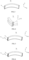
FIG. 3 is a schematic three-dimensional structural diagram of a reinforcement member in a liquid cooling plate provided by an embodiment of the present disclosure; -
FIG. 4 is another schematic three-dimensional structural diagram of a reinforcement member in a liquid cooling plate provided by an embodiment of the present disclosure; -
FIG. 5 is still another schematic three-dimensional structural diagram of a reinforcement member in a liquid cooling plate provided by an embodiment of the present disclosure; -
FIG. 6 is still another schematic three-dimensional structural diagram of a reinforcement member in a liquid cooling plate provided by an embodiment of the present disclosure; -
FIG. 7 is still another schematic three-dimensional structural diagram of a reinforcement member in a liquid cooling plate provided by an embodiment of the present disclosure; -
FIG. 8 is still another schematic three-dimensional structural diagram of a reinforcement member in a liquid cooling plate provided by an embodiment of the present disclosure; -
FIG. 9 is a schematic three-dimensional structural diagram of a first cooling plate in the liquid cooling plate provided by an embodiment of the present disclosure; -
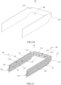
FIG. 10 is a schematic three-dimensional structural diagram of a second cooling plate in the liquid cooling plate provided by an embodiment of the present disclosure; -
FIG. 11 is another schematic three-dimensional structural diagram of a second cooling plate in the liquid cooling plate provided by an embodiment of the present disclosure; -
FIG. 12 is a schematic three-dimensional cross-sectional view of the liquid cooling plate shown inFIG. 1 along the line XII-XII provided by an embodiment of the present disclosure; -
FIG. 13 is an enlarged schematic view of the liquid cooling plate at XIII shown inFIG. 12 provided by an embodiment of the present disclosure; -
FIG. 14 is a schematic three-dimensional exploded structural diagram of a liquid cooling plate provided by an embodiment of the present disclosure; -
FIG. 15 is another schematic three-dimensional exploded structural diagram of a liquid cooling plate provided by an embodiment of the present disclosure; -
FIG. 16 is still another schematic three-dimensional exploded structural diagram of a liquid cooling plate provided by an embodiment of the present disclosure; and -
FIG. 17 is a schematic three-dimensional structural diagram of a battery pack provided by an embodiment of the present disclosure. -
-
Liquid cooling plate 100; - First cooling
plate 10,first body 11,first segment 111,second segment 113,third segment 115,end 112, firstbent part 117,first connection part 12,first flow passage 13, firstsub flow passage 131, secondsub flow passage 133,second connection part 14, firstflow disturbing part 15; - First through-
hole 20; -
Second cooling plate 30,second body 31,fourth segment 311,fifth segment 313,sixth segment 315,end 312, secondbent part 317,third connection part 32,second flow passage 33, thirdsub flow passage 331, fourthsub flow passage 333,fourth connection part 34, secondflow disturbing part 35; - Second through-
hole 40; -
Cooling flow passage 50; -
Liquid inlet pipe 60; -
Reinforcement member 70,passage 71,air hole 72,sub passage 711,spacer sheet 73, first sub-part 75, second sub-part 76, third sub-part 77; -
Liquid outlet pipe 80; -
Accommodating space 90; -
Battery module 300; -
Upper cover 400; -
Lower box body 500; and -
Battery pack 1000. - The technical solutions in the embodiments of the present disclosure will be clearly and completely described below with reference to the accompanying drawings in the embodiments of the present disclosure. Obviously, the described embodiments are only some of the embodiments of the present disclosure, but not all the embodiments. Based on the embodiments in the present disclosure, all other embodiments obtained by those of ordinary skill in the art without creative efforts fall within the protection scope of the present disclosure.
- The embodiments are described below with reference to the accompanying drawings, illustrating specific embodiments of the present disclosure that can be implemented. The directional terms mentioned herein, such as "up", "down", "front", "back", "left", "right", "inside", "outside", "side", etc., are only with reference to the orientations of the drawings. Therefore, the directional terms used are for the purpose of better and clearer description and understanding of the present disclosure and do not indicate or imply that any device or component referred to must have a particular orientation or be constructed and operated in a particular orientation, and therefore cannot be construed as any limitation on the present disclosure.
- In addition, the serial numbers assigned to components herein, such as "first", "second", etc., are only used to distinguish the described objects and do not have any sequential or technical meaning. The terms "connecting" and "coupling" mentioned in the present disclosure comprise direct and indirect connecting (coupling) unless otherwise specified.
- Referring to
FIG. 1 and FIG. 2 , in an embodiment of the present disclosure, there is provided aliquid cooling plate 100. Theliquid cooling plate 100 comprises afirst cooling plate 10, asecond cooling plate 30 and at least onereinforcement member 70. Thefirst cooling plate 10 comprises a firstbent part 117. Thesecond cooling plate 30 is arranged side by side with thefirst cooling plate 10 and is connected with thefirst cooling plate 10 in a sealed manner. Acooling flow passage 50 is formed between thesecond cooling plate 30 and thefirst cooling plate 10. Thesecond cooling plate 30 comprises a secondbent part 317. The secondbent part 317 corresponds to the firstbent part 117. The at least onereinforcement member 70 is disposed in thecooling flow passage 50 between the firstbent part 117 and the secondbent part 317. - An independent battery module usually contains multiple cells. During the charging and discharging process of the battery module, the chemical reactions of the multiple cells inside the battery module will generate a large amount of heat. Currently, a liquid cooling plate is often used to exchange heat with the battery module. However, at present, a battery pack is usually composed of multiple battery modules so as to form a high-power battery, and when the liquid cooling plate is used to exchange heat with the multiple battery modules, it is often necessary to perform bending process on the liquid cooling plate to increase the heat exchange area between the liquid cooling plate and the battery modules and improve the efficiency of the heat exchange between the liquid cooling plate and the battery modules. When the liquid cooling plate is bent, however, a flow passage at the bent part is easy to deform, causing the flow passage at the bend to crack.
- In the
liquid cooling plate 100 of the present disclosure, at least onereinforcement member 70 is provided between the firstbent part 117 of thefirst cooling plate 10 and the secondbent part 317 of thesecond cooling plate 30. The at least onereinforcement member 70 can provide supporting force for side walls of thecooling flow passage 50 between the firstbent part 117 and the secondbent part 317, thereby preventing thecooling flow passage 50 at the bent part from deforming and breaking, and ensuring the consistency of thecooling flow passage 50. - Referring to
FIG. 2 , thefirst cooling plate 10 and thesecond cooling plate 30 are a pair of components, and the number of thefirst cooling plates 10 is consistent with the number of thesecond cooling plates 30. Thefirst cooling plate 10 and thesecond cooling plate 30 are together formed with anaccommodating space 90, theaccommodating space 90 is used to place thebattery modules 300 therein, and thecooling flow passage 50 surrounds theaccommodating space 90. Specifically, thesecond cooling plate 30 is arranged side by side with thefirst cooling plate 10 on a side of thefirst cooling plate 10 closer to theaccommodating space 90. - The number of the
first cooling plates 10 and the number of thesecond cooling plates 30 may be one or more so as to perform heat exchange for a larger number ofbattery modules 300. - The
first cooling plate 10 and thesecond cooling plate 30 are of the same material, which can be a metal material, or a non-metallic material with good thermal conductivity. The specific material is not limited herein. In an example, thefirst cooling plate 10 and thesecond cooling plate 30 can be made of aluminum, which can reduce the weight of theliquid cooling plate 100, thereby reducing the overall weight of thebattery pack 1000. - Please refer to
FIGS. 2 and3 . In an embodiment, apassage 71 is formed in thereinforcement member 70. Thepassage 71 penetrates thereinforcement member 70 along the extension direction of thecooling flow passage 50 and is communicated with thecooling flow passage 50. - In an example, the
reinforcement member 70 may be made of metal material, thereby increasing the strength of thereinforcement member 70. - The
reinforcement member 70 can be fixedly installed on the side wall of the firstbent part 117 through welding connection, and then thesecond cooling plate 30 is connected with thefirst cooling plate 10 through welding connection in a sealed manner; or thereinforcement member 70 is fixedly installed on the side wall of the secondbent part 317 through welding connection, and then thesecond cooling plate 30 is connected with thefirst cooling plate 10 through welding connection in a sealed manner. - Specifically, the
reinforcement member 70 has an arc-shaped structure as a whole, and a curvature in which thereinforcement member 70 is bent is the same as the curvature in which the firstbent part 117 is bent and the curvature in which the secondbent part 317 is bent, so that when thereinforcement member 70 is disposed in thecooling flow passage 50 between the firstbent part 117 and the secondbent part 317, the side surfaces of thereinforcement member 70 can be attached to the side walls on both sides of thecooling flow passage 50, thereby providing support force for thecooling flow passage 50 between the firstbent part 117 and the secondbent part 317, preventing the side walls of thecooling flow passage 50 between the firstbent part 117 and the secondbent part 317 from deforming and breaking, ensuring the consistency of thecooling flow passage 50, and ensuring the safety of theliquid cooling plate 100. - By providing the
passage 71, it ensures the smoothness of thecooling flow passage 50 after thereinforcement member 70 is added. When the heat exchange medium in thecooling flow passage 50 flows through thereinforcement member 70 between the firstbent part 117 and the secondbent part 317, the heat exchange medium can flow into the remaining of thecooling flow passage 50 through thepassage 71 of thereinforcement member 70. - The number of
passages 71 is one, as shown inFIG. 3 . The height of the passage 71 (the height refers to the distance extending in the Y direction shown inFIG. 3 ) is within a preset range of the height of thereinforcement member 70. For example, the height of thepassage 71 is 80% to 90% of the height of thereinforcement member 70, if the height of thereinforcement 70 is noted as H, the height of thepassage 71 can be 80%H, 81%H, 82%H, 83%H, 84%, 85%H, 86%H, 87%H, 88%H, 89%H, or 90%H, thereby keeping the volumes of the heat exchange medium before and after flowing through thereinforcement 70 as consistent as possible to avoid the large lateral impact force generated by the heat exchange medium at the bent part due to the large change in flow rate, thereby preventing the firstbent part 117 of thefirst cooling plate 10 from breaking. In addition, it can also improve the cooling or preheating efficiency of thebattery modules 300 by theliquid cooling plate 100. - Please refer to
FIGS. 2 and4 . In another embodiment, the number ofpassages 71 may be multiple. Themultiple passages 71 are arranged side by side in the Y direction, and the cross-sectional projection of thereinforcement member 70 is square-wave-shaped. The side walls of two of thepassages 71 are respectively attached to the firstbent part 117 of thefirst cooling plate 10, and the side walls of thepassage 71 located in the middle position are attached to the secondbent part 317 of thesecond cooling plate 30. In this way, the thickness of thefirst cooling plate 10 at the first bent part 117 (the distance extended in the X direction as shown inFIG. 4 ) is increased, which prevents the firstbent part 117 of thefirst cooling plate 10 from breaking due to a too large lateral impact force generated by the heat exchange medium when flowing throughpassage 71. - Please refer to
FIG. 5 . In another embodiment, thereinforcement member 70 further comprises a plurality ofspacer sheets 73. The plurality ofspacer sheets 73 are disposed in thepassage 71 along the extension direction of thepassage 71 and divide thepassage 71 into a plurality ofsub passages 711, and the plurality ofsub passages 711 are all communicated with the cooling flow passage 50 (shown inFIG. 2 ). - The
spacer sheets 73 may be metal reinforcement ribs, thereby effectively preventing thespacer sheets 73 from breaking due to thespacer sheets 73 being impacted by the heat exchange medium for a long time. - For example, as shown in
FIG. 5 , a plurality ofspacer sheets 73 can be arranged side by side and in parallel in the height direction of the reinforcement member 70 (the Y direction shown inFIG. 5 ), and the intervals between twoadjacent spacer sheets 73 are the same, so that thepassage 71 is divided into a plurality ofsub passages 711 in the height direction. In this way, the entire side wall of thepassage 71 can be attached to the side wall of the firstbent part 117. Compared with thereinforcement member 70 described in the previous embodiment, thereinforcement member 70 in the present embodiment can allow thefirst cooling plate 10 as a whole to be thickened at the firstbent part 117, and the lateral impact force generated by the heat exchange medium when flowing through the plurality ofsub passages 711 can all be forced on the first side of thereinforcement member 70 to prevent the heat exchange medium from directly impacting thefirst cooling plate 10, thereby avoiding the crack of thefirst cooling plate 10 at the firstbent part 117, and effectively increasing the service life of thefirst cooling plate 10. - For another example, as shown in
FIG. 6 , the plurality ofspacer sheets 73 are arranged side by side in thepassage 71 in the height direction of thepassage 71, the plurality ofspacer sheets 73 are divided into multiple groups, each group comprises twospacer sheets 73. The twospacer sheets 73 of each group are arranged in a V shape in thepassage 71, and thespacer sheets 73 in different groups are not connected with each other. - For another example, as shown in
FIG. 7 , the plurality ofspacer sheets 73 are arranged side by side in thepassage 71 in the height direction of thepassage 71. Except for the twospacer sheets 73 located outermost in the height direction of thepassage 71, the remainingspacer sheets 73 are connected end to end, so that fouradjacent spacers 73 form an M shape. - Please refer to
FIG. 8 . In yet another embodiment, thereinforcement member 70 comprises afirst sub-part 75, asecond sub-part 76 and at least onethird sub-part 77. Thefirst sub-part 75 and thesecond sub-part 76 are arranged oppositely, and two ends of the at least onethird sub-part 77 are connected with thefirst sub-part 75 and thesecond sub-part 76 respectively. The at least onethird sub-part 77 divides thepassage 71 into at least twosub passages 711. The number of the third sub-parts 77 may be one or more. When the number of thethird sub-parts 77 is one, the structure of thereinforcement member 70 is as shown inFIG. 8 . When the number of third sub-parts 77 is multiple, the multiplethird sub-parts 77 are arranged in parallel between thefirst sub-part 75 and thesecond sub-part 76, dividing thepassage 71 into a plurality ofsub passages 711. - Please refer to
FIG. 8 . In another embodiment, thereinforcement member 70 may be made of foam metal. The foam metal is formed with a plurality ofair holes 72, and the plurality ofair holes 72 are communicated with thecooling flow passage 50 to allow the heat exchange medium in thecooling flow passage 50 to pass through. The heat exchange medium can enter thecooling flow passage 50 through the plurality of air holes 72. The foam metal is arranged between the firstbent part 117 and the secondbent part 317, which can slow down the flow rate of the heat exchange medium flowing through thereinforcement member 70, thereby reducing the lateral impact force generated by the heat exchange medium when flowing through thereinforcement member 70, and avoiding cracking of the firstbent part 117 of thefirst cooling plate 10. - The heat exchange medium comprises a liquid (such as water, water-alcohol mixture) medium. For example, in an example, the heat exchange medium may be water.
- Referring to
FIGS. 2 and17 , it should be noted that the heat exchange medium can cool or preheat thebattery modules 300. When thebattery modules 300 need to be heat exchanged, the heat exchange medium is input into thecooling flow passage 50. Since thebattery modules 300 are attached to theliquid cooling plate 100, the heat exchange medium in thecooling flow passage 50 can perform heat exchange through theliquid cooling plate 100. Thebattery modules 300 can be cooled or preheated by adjusting the temperature of the input heat exchange medium. - In some embodiments, in a low-temperature environment, the
battery modules 300 have reduced charging and discharging performance due to the reduced activity of positive and negative electrode materials and the reduced conductivity of the electrolyte of the battery cells in thebattery modules 300. In this case, it needs to introduce the heat exchange medium with higher temperature into thecooling flow passage 50 so as to allow thebattery modules 300 to reach a suitable temperature. At the same time, theliquid cooling plate 100 can be attached tomultiple battery modules 300, so that theliquid cooling plate 100 can exchange heat with themultiple battery modules 300, effectively improving the preheating efficiency of theliquid cooling plate 100 for thebattery pack 1000. - In some embodiments, in a high-temperature environment, the charging efficiency of the cells in the
battery modules 300 will be low and the battery capacity will be reduced, and thebattery modules 300 will dissipate heat during operation, resulting in the temperature of thebattery modules 300 too high, and thus the heat of thebattery modules 300 needs to be dissipated through theliquid cooling plate 100. In this case, it needs to introduce the heat exchange medium with a lower temperature into thecooling flow passage 50 so that the heat exchange medium in thecooling flow passage 50 can take away the heat dissipated by thebattery module 300 to allow the temperature of thebattery module 300 to be reduced to a suitable temperature. At the same time, theliquid cooling plate 100 is attached tomultiple battery modules 300, so that theliquid cooling plate 100 can exchange heat with themultiple battery modules 300 at the same time, effectively improving the cooling efficiency of theliquid cooling plate 100 for thebattery pack 1000. - In an embodiment of the present disclosure, multiple columns of
battery modules 300 are placed in theaccommodating space 90 so that theliquid cooling plate 100 is attached to the multiple columns ofbattery modules 300, thereby improving the cooling efficiency of theliquid cooling plate 100 for thebattery modules 300. - Please refer to
FIGS. 9 and10 . In an embodiment, thefirst cooling plate 10 comprises afirst body 11 and afirst flow passage 13 provided on thefirst body 11. Thefirst flow passage 13 extends along the length direction of thefirst body 11 and is formed by recessing from thefirst body 11 in a direction away from theaccommodating space 90. Thesecond cooling plate 30 is connected with thefirst body 11 in a sealed manner, and thefirst flow passage 13 and thesecond cooling plate 30 are matched to form thecooling flow passage 50 surrounding theaccommodating space 90. - The
first flow passage 13 comprises a firstsub flow passage 131 and a secondsub flow passage 133 distributed in thefirst body 11. The firstsub flow passage 131 and the secondsub flow passage 133 are communicated with each other, and the connected firstsub flow passage 131 and secondsub flow passage 133 together form thefirst flow passage 13 in an annular shape. The firstsub flow passage 131 and the secondsub flow passage 133 are connected at theends 112 of thefirst body 11, and other part of the firstsub flow passage 131 and other part of the secondsub flow passage 133 are arranged in parallel at intervals in the height direction Y of thefirst body 11, that is, the interval part space therebetween is not provided with any flow passage. In addition, thefirst flow passage 13 is not provided on the peripheral edge portion of thefirst body 11, and the portion of thefirst body 11 that is not provided with thefirst flow passage 13 is used to abut against thesecond cooling plate 30. - The surface of the
second cooling plate 30 is flat. In this case, thecooling flow passage 50 of theliquid cooling plate 100 is thefirst flow passage 13. The peripheral edge portion of thefirst body 11 that is not provided with thefirst flow passage 13 abuts against thesecond cooling plate 30, and the interval part between the firstsub flow passage 131 and the secondsub flow passage 133 abuts against thesecond cooling plate 30. Thefirst body 11 and thesecond cooling plate 30 are fixedly connected by welding, and thefirst flow passage 13 on thefirst body 11 is sealed, which can effectively prevent the cooling medium in thefirst flow passage 13 from leaking. - Referring to
FIGS. 9 and11 , in another embodiment, thesecond cooling plate 30 comprises asecond body 31 and asecond flow passage 33 provided in thesecond body 31. Thesecond body 31 is arranged side by side with thefirst body 11 on the side of thefirst body 11 facing theaccommodating space 90. Thesecond flow passage 33 extends along the length direction of thesecond body 31 and is formed by recessing from thesecond body 31 in a direction toward theaccommodating space 90. Thesecond flow passage 33 corresponds to thefirst flow passage 13, and the width of thesecond flow passage 33 is equal to the width of thefirst flow passage 13. In a case where thefirst body 11 and thesecond body 31 are connected with each other in a sealed manner, thesecond flow passage 33 and thesecond flow passage 33 are matched to jointly form thecooling flow passage 50 surrounding theaccommodating space 90. - Similarly, the
first flow passage 13 comprises a firstsub flow passage 131 and a secondsub flow passage 133 distributed in thefirst body 11. The firstsub flow passage 131 and the secondsub flow passage 133 are communicated with each other, and the connected firstsub flow passage 131 and secondsub flow passage 133 together form thefirst flow passage 13 in an annular shape. - Specifically, the first
sub flow passage 131 and the secondsub flow passage 133 are connected at theends 112 of thefirst body 11, and the other part of the firstsub flow passage 131 and the other part of the secondsub flow passage 133 are arranged in parallel at intervals in the height direction Y, that is, the interval part spaced therebetween is not provided with any flow passage. Thesecond flow passage 33 comprises a thirdsub flow passage 331 and a fourthsub flow passage 333 distributed in thesecond body 31. The thirdsub flow passage 331 and the fourthsub flow passage 333 are communicated with each other, and the connected thirdsub flow passage 331 and fourthsub flow passage 333 together form thesecond flow passage 33 in an annular shape. Therefore, thecooling flow passage 50 formed jointly by the matchedfirst passage 13 andsecond passage 33 is in an annular shape as a whole. Similarly, the thirdsub flow passage 331 and the fourthsub flow passage 333 are connected at theends 312 of thesecond body 31, and the other part of the thirdsub flow passage 331 and the other part of the fourthsub flow passage 333 are arranged in parallel at intervals in the height direction Y. As such, one of the sub flow passages (for example, the firstsub flow passage 131 or the third sub flow passage 331) can be used to be connected with aliquid inlet pipe 60 to input heat exchange medium into the flow passage, and another one of the sub flow passages (such as the secondsub flow passage 133 or the fourth sub flow passage 333) can be used to connect the heat exchange medium after heat exchange to aliquid outlet pipe 80 to discharge it out of thecooling flow passage 50. There is no flow passage provided in the interval part, and the interval part between the thirdsub flow passage 331 and the fourthsub flow passage 333 and the interval part between the firstsub flow passage 131 and the secondsub flow passage 133 abut against each other - The
first flow passage 13 and thesecond flow passage 33 being matched to form thecooling flow passage 50 means that when thefirst body 11 and thesecond body 31 are attached and welded to each other to form theliquid cooling plate 100, the part of thefirst body 11 that is not provided with thefirst flow passage 13 and the part of thesecond body 31 that is not provided with thesecond flow passage 33 abut against each other, thefirst flow passage 13 and thesecond flow passage 33 are opposite in the thickness direction of theliquid cooling plate 100, and thefirst flow passage 13 and thesecond flow passage 33 together form thecooling flow passage 50. - Specifically, the
first flow passage 13 is not provided on the peripheral edge of thefirst body 11, and thesecond flow passage 33 is not provided on the peripheral edge of thesecond body 31. When thefirst body 11 and thesecond body 31 are welded, the peripheral edge of thefirst body 11 and the peripheral edge of thesecond body 31 can be welded so that thefirst body 11 and thesecond body 31 are connected in a sealed manner, and thusfirst flow passage 13 and thesecond flow passage 33 are sealed, which can effectively prevent the heat exchange medium in thefirst flow passage 13 from leaking. - Alternatively, when the peripheral edges of the
first body 11 and thesecond body 31 are weld, the interval part between the thirdsub flow passage 331 and the fourthsub flow passage 333 and the interval part between the firstsub flow passage 131 and the secondsub flow passage 133 can also abut against each other and then welded with each other so as to strengthen the stability of the welding between thefirst cooling plate 10 and thesecond cooling plate 30. - Compared with the
cooling flow passage 50 formed by thefirst flow passage 13, thecooling flow passage 50 jointly formed by the matchedsecond flow passage 33 andfirst flow passage 13, with the addition of thesecond flow passage 33, results in a larger volume of thecooling flow passage 50, and more heat exchange medium can be input into thecooling flow passage 50 at one time, which effectively improves the heat exchange efficiency between the heat exchange medium and thebattery modules 300. In the present disclosure, the structure of theliquid cooling plate 100 is described in detail in an example where thefirst cooling plate 10 is formed with thefirst flow passage 13 and thesecond cooling plate 30 is formed with thesecond flow passage 33. - In an embodiment of the present disclosure, a width of the
second flow passage 33 is equal to a width of thefirst flow passage 13. When thefirst body 11 and thesecond body 31 are opposite and attached to each other, the side wall of thefirst flow passage 13 can abut against the side wall of thesecond flow passage 13, sealing thefirst flow passage 13 and thesecond flow passage 33. - Please refer to
FIGS. 12 and 13 , thefirst cooling plate 10 further comprises a firstflow disturbing part 15 provided on thefirst flow passage 13 along the extension direction of thefirst flow passage 13. The firstflow disturbing part 15 is formed to protrude from the side wall of thefirst flow passage 13 in the direction toward theaccommodating space 70. - The number of first
flow disturbing parts 15 is multiple, and the multiple firstflow disturbing parts 15 may be evenly distributed on the side wall of thefirst flow passage 13, or the multiple firstflow disturbing parts 15 may be unevenly spaced on the side wall of thefirst flow passage 13. By providing the firstflow disturbing parts 15, the heat exchange medium input into thefirst flow passage 13 can be diverted, which increases the flow path of the heat exchange medium in thefirst flow passage 13, and effectively prolongs the time duration of the heat exchange between the heat exchange medium and thebattery modules 300, thereby achieving higher heat exchange efficiency. - The first
flow disturbing part 15 has a hemispherical structure. When the heat exchange medium in thefirst flow passage 13 passes the surface of the firstflow disturbing part 15, the heat exchange medium can flow around the firstflow disturbing part 15, so as to form a reverse flow around the firstflow disturbing part 15, prolonging the time duration of the heat exchange between the heat exchange medium and thebattery modules 300, thereby improving the heat exchange efficiency. - Similarly, the
second cooling plate 30 also comprises a secondflow disturbing part 35 provided on thesecond flow passage 33 along the extension direction of thesecond flow passage 33. Thesecond spoiler 35 is formed to protrude from the side wall of thesecond flow passage 33 in a direction away from theaccommodating space 90. The structure of the secondflow disturbing part 35 is the same as that of the firstflow disturbing part 15. The number of the secondflow disturbing parts 35 is the same as the number of the firstflow disturbing parts 15, which will not be described again. - In an embodiment, when the
first body 11 and thesecond body 31 are connected in a sealed manner, the firstflow disturbing parts 15 and the secondflow disturbing parts 35 may be arranged to be staggered, and the firstflow disturbing parts 15 and the secondflow disturbing parts 35 are both used to divert the heat exchange medium in thecooling flow passage 50 so as to increase the fluidity of the heat exchange medium in theflow passage 50, thereby improving the heat exchange efficiency between the heat exchange medium and thebattery modules 300. - In another embodiment, when the
first body 11 and thesecond body 31 are connected in a sealed manner, the firstflow disturbing parts 15 and the secondflow disturbing parts 35 abut against each other. - The depth that the
first flow passage 13 is recessed is equal to the height that the firstflow disturbing part 15 protrudes, and the depth that thesecond flow passage 33 is recessed is equal to the height that the secondflow disturbing part 35 protrudes. Therefore, when the peripheral edge surface of thefirst body 11 and the peripheral edge surface of thesecond body 31 are welded, both of the firstflow disturbing parts 15 and the secondflow disturbing parts 35 will not affect the sealing of the connection between thefirst body 11 and thesecond body 31, ensuring the sealing of the connection between thefirst body 11 and thesecond body 31. - Referring to
FIG. 9 , thefirst body 11 comprises afirst segment 111, two firstbent parts 117, asecond segment 113 and athird segment 115. Two ends of one of the firstbent parts 117 are connected with thefirst segment 111 and thesecond segment 113 respectively, and two ends of the other firstbent part 117 are connected with thethird segment 115 and thesecond segment 113 respectively. Thesecond segment 113 is located between thefirst segment 111 and thethird segment 115. - In an embodiment of the present disclosure, the
first segment 111, the two firstbent parts 117, thesecond segment 113 and thethird segment 115 are of an integral structure, and thefirst body 11 is obtained through stamping and bending process using a profiling mold. Thefirst segment 111, the two firstbent parts 117, thesecond segment 113 and thethird segment 115 are connected without a connecting structure such as a quick-connect connector, and there is no interface for connection through a quick-connect connector between the three, and there is no leakage failure of the heat exchange medium in thefirst flow passage 13, so that theliquid cooling plate 100 has high safety performance. Moreover, thefirst segment 111, the two firstbent parts 117, thesecond segment 113 and thethird segment 115 do not need any connection structure such as quick-plug connectors for connection, which can effectively reduce the cost. - Please refer to
FIG. 17 . Thefirst segment 111, the two firstbent parts 117, thesecond segment 113 and thethird segment 115 connected in sequence form a U-shaped structure. Thefirst segment 111 and thethird segment 115 are opposite. The length of thefirst segment 111 and the length of thethird segment 115 can be set according to the length of thebattery module 300. Specifically, the length of thefirst segment 111 and the length of thethird segment 115 are slightly larger than the length of one column ofbattery modules 300. Thesecond segment 113 corresponds to the width of the two columns ofbattery modules 300, and the length of thesecond segment 113 is slightly larger than the width of thebattery modules 300, ensuring that two columns ofbattery modules 300 can be placed in theaccommodating space 90. - Referring to
FIGS. 9 and11 , similarly, thesecond body 31 comprises afourth segment 311, two secondbent parts 317, afifth segment 313 and asixth segment 315. Thefourth segment 311 corresponds to thefirst segment 111 and is matched and connected with thefirst segment 111. Two ends of one of the two secondbent parts 317 are respectively connected with thefifth segment 313 and thefourth segment 311, and thefifth segment 313 corresponds to and is matched and connected with thesecond segment 113. Two ends of the other one of the two secondbent parts 317 are respectively connected with thesixth segment 315 and thefifth segment 313. Thesixth segment 315 corresponds to and is matched and connected with thethird segment 115. Thefifth segment 313 is located between thefourth segment 311 andsixth segment 315. - In an embodiment of the present disclosure, the
fourth segment 311, the two secondbent parts 317, thefifth segment 313 and thesixth segment 315 are of an integral structure, and thesecond body 31 is obtained through stamping and bending process using a profiling mold. Thefourth segment 311, the two secondbent parts 317, thefifth segment 313 and thesixth segment 315 do not need to be connected through a connection structure such as a quick-connect connector, there is no interface for connection through a quick connector between the three, and there is no leakage failure of the heat exchange medium in thefirst flow passage 13, so that theliquid cooling plate 100 has high safety performance. Moreover, thefourth segment 311, the two secondbent parts 317, thefifth segment 313, and thesixth segment 315 do not need a connection structure such as a quick-plug connector for connection, which can effectively reduce the cost. - Please refer to
FIG. 17 , thefourth segment 311, the two secondbent parts 317, thefifth segment 313 and thesixth segment 315 connected in sequence form a U-shaped structure. Thefourth segment 311 and thesixth segment 315 are opposite. The length of thefourth segment 311 and the length of thesixth segment 315 can be set according to the length of a column ofbattery modules 300 and can be equal to the length of thefirst segment 111 and the length of thethird segment 115 respectively. Specifically, the length of thefourth segment 311 and the length of thesixth segment 315 are both slightly larger than the length of thebattery modules 300. Thefifth segment 313 corresponds to the width of the two columns ofbattery modules 300, and the length of thefifth segment 313 is greater than the width of the two columns ofbattery modules 300, ensuring that the two columns ofbattery modules 300 can be placed in theaccommodating space 90. - It should be noted that the
first segment 111, the two firstbent parts 117, thesecond segment 113, and thethird segment 115 may be in separate structures. Thefirst segment 117, the two firstbent parts 117, thesecond segment 113, and thethird segment 115 are connected by welding. Similarly, thefourth segment 311, the two secondbent parts 317, thefifth segment 313, and thesixth segment 315 may be in separate structures. Thefourth segment 311, the two secondbent parts 317, thefifth segment 313 and thesixth segment 315 are connected by welding. Specifically, when thefirst body 11 and thesecond body 31 are welded to form theliquid cooling plate 100, thefirst segment 111 and thefourth segment 311 are attached to each other, the firstbent part 117 and the secondbent part 317 are attached to each other, thesecond segment 113 and thefifth segment 313 are attached to each other, and thethird segment 115 and thesixth segment 315 are attached to each other. When theliquid cooling plate 100 exchanges heat with the four columns ofbattery modules 300, thefirst segment 111 and thefourth segment 311 are respectively located between the third column ofbattery modules 300 and the fourth column ofbattery modules 300, and thefirst segment 111 and thefourth segment 311 are used to exchange heat with the third column ofbattery modules 300 and the fourth column ofbattery modules 300. Thethird segment 115 and thesixth segment 315 are located between the first column ofbattery modules 300 and the second column ofbattery modules 300, and thethird segment 115 and thesixth segment 315 are used to exchange heat with the first column ofbattery modules 300 and the second column ofbattery modules 300. When the heat exchange medium is introduced into thecooling flow passage 50, the heat dissipated by the four columns ofbattery modules 300 is exchanged with the heat exchange medium in thecooling flow passage 50 through thefirst segment 111, thefourth segment 311, thethird segment 115 and thesixth segment 315. - In an embodiment of the present disclosure, the number of the first
flow disturbing parts 15 on thefirst segment 111 and thethird segment 115 is greater than the number of the firstflow disturbing parts 15 on thesecond segment 113, and the number of the secondflow disturbing parts 35 on thefourth segment 311 and thesixth segment 315 is greater than the number of the secondflow disturbing parts 35 on thefifth segment 313, ensuring a longer time duration of the heat exchange between the heat exchange medium in thecooling flow passage 50 of theliquid cooling plate 100 and thebattery modules 300, thereby improving the heat exchange efficiency. - Please continue to refer to
FIG. 7 and FIG. 9 . The firstsub flow passage 131 and the secondsub flow passage 133 extend through thefirst segment 111, thesecond segment 113 and thethird segment 115. The thirdsub flow passage 331 and the fourthsub flow passage 333 extend through thefourth segment 311, thefifth segment 313 and thesixth segment 315. The firstsub flow passage 131 corresponds to the thirdsub flow passage 331, the width of the firstsub flow passage 131 is equal to the width of the thirdsub flow passage 331, the secondsub flow passage 133 corresponds to the fourthsub flow passage 333, and the width of the secondsub flow passage 133 is equal to the width of the fourthsub flow passage 333. - Please refer to
FIG. 3 . In an embodiment of the present disclosure, the number ofreinforcement members 70 is multiple. Themultiple reinforcement members 70 are disposed in the firstsub flow passage 131 and the thirdsub flow passage 331 between the firstbent part 117 and the secondbent part 317, and themultiple reinforcement members 70 are disposed in the secondsub flow passage 133 and the fourthsub flow passage 333 between the firstbent part 117 and the secondbent part 317. - The width of the first
sub flow passage 131 at thefirst segment 111 and the width of the firstsub flow passage 131 at thethird segment 115 are both greater than or equal to the width of the firstsub flow passage 131 at thesecond segment 113. The width of the secondsub flow passage 133 of thefirst segment 111 and the width of the secondsub flow passage 133 of thethird segment 115 are both greater than or equal to the width of the secondsub flow passage 133 of thesecond segment 113. The width of the firstsub flow passage 131 at thefirst segment 111 and the width of the firstsub flow passage 131 at thethird segment 115 are both greater than or equal to the width of the firstsub flow passage 131 at the firstbent part 117. The width of the secondsub flow passage 133 at thefirst segment 111 and the width of the secondsub flow passage 133 at thethird segment 115 are both greater than or equal to the width of the secondsub flow passage 133 at the firstbent part 117. In the present disclosure, the firstsub flow passage 131 and the secondsub flow passage 133 with a larger width are provided in the part where thefirst cooling plate 10 and the battery module 300 (shown inFIG. 17 ) have a larger contact area, which can effectively improve the heat exchange efficiency. - The width of the third
sub flow passage 331 of thefourth segment 311 and the width of the thirdsub flow passage 331 of thesixth segment 315 are both greater than or equal to the width of the thirdsub flow passage 331 of thefifth segment 313 . The width of the fourthsub flow passage 333 of thefourth segment 311 and the width of the fourthsub flow passage 333 of thesixth segment 315 are both greater than or equal to the width of the fourthsub flow passage 333 of thefifth segment 313. The width of the thirdsub flow passage 331 of thefourth segment 311 and the width of the thirdsub flow passage 331 of thesixth segment 315 are both greater than or equal to the width of the thirdsub flow passage 331 of the secondbent part 317. The width of the fourthsub flow passage 333 of thefourth segment 311 and the width of the fourthsub flow passage 333 of thesixth segment 315 are both greater than or equal to the width of the fourthsub flow passage 333 of the secondbent part 317. In the present disclosure, the thirdsub flow passage 331 and the fourthsub flow passage 333 with a larger width are provided in the part where thesecond cooling plate 30 has a larger contact area with thebattery modules 300, which can effectively improve the heat exchange efficiency. - It should be noted that the width of each of the sub flow passages mentioned above refers to the length of the sub flow passage extending in the Y direction shown in
FIG. 2 . - Please refer to
FIG. 14 . In an embodiment, thesecond segment 113 is provided with a first through-hole 20 connected with the firstsub flow passage 131, and thesecond segment 113 is provided with a second through-hole 40 connected with the secondsub flow passage 133. The first through-hole 20 is used to connect one of theliquid inlet pipe 60 and theliquid outlet pipe 80, and the second through-hole 40 is used to connect the other of theliquid inlet pipe 60 and theliquid outlet pipe 80. For example, the first through-hole 20 is used to connect theliquid inlet pipe 60, and the second through-hole 40 is used to connect theliquid outlet pipe 80. In this case, when the heat exchange medium is input into theliquid inlet pipe 60, the heat exchange medium flows into the sub flow passage formed by the firstsub flow passage 131 and the thirdsub flow passage 331 through the first through-hole 20, and then flows into the sub flow passage jointly formed by the secondsub flow passage 133 and the fourthsub flow passage 333, and is finally discharged from theliquid outlet pipe 80 connected to the second through-hole 40. In this embodiment, in the Y direction, the center of the first through-hole 20 and the center of the second through-hole 40 are located on a straight line; or, in the Y direction, the center of the first through-hole 20 and the center of the second through-hole 40 are located on different straight lines. - Please refer to
FIG. 15 . In another embodiment, thefifth segment 313 is provided with a first through-hole 20 connected with the thirdsub flow passage 331, and thefifth segment 313 is provided with a second through-hole 40 connected with the fourthsub flow passage 333. The first through-hole 20 is used to connect one of theliquid inlet pipe 60 and theliquid outlet pipe 80, and the second through-hole 40 is used to connect the other of theliquid inlet pipe 60 and theliquid outlet pipe 80. The present embodiment differs from the above-mentioned embodiments in that the first through-hole 20 and the second through-hole 40 are provided on thefifth segment 313 of thesecond body 31. In this case, theliquid inlet pipe 60 and theliquid outlet pipe 80 extend into theaccommodating space 90 from the bottom of theliquid cooling plate 100 and are connected with the first through-hole 20 and the second through-hole 40. - Please refer to
FIG. 16 . In yet another embodiment, thefirst cooling plate 10 further comprises afirst connection part 12 and asecond connection part 14 disposed on thesecond segment 113. Thefirst connection part 12 is spaced apart from thesecond connection part 14. Thefirst connection part 12 is provided with afirst opening 121. Thesecond connection part 14 is provided with athird flow passage 141 connected with the firstsub flow passage 131. Thethird flow passage 141 is formed by recessing from thesecond connection part 14 in a direction away from theaccommodating space 90. Thesecond connection part 14 is provided with asecond opening 143 that is connected with thethird flow passage 141. - The
second cooling plate 30 further comprises athird connection part 32 and afourth connection part 34 provided on thefifth segment 313. Thethird connection part 32 is spaced apart from thefourth connection part 34, thethird connection part 32 is matched with thefirst connection part 12, and thefourth connection part 34 is matched with thesecond connection part 14. Thethird connection part 32 is provided with athird opening 321, and thethird opening 321 corresponds to thefirst opening 121. Thefourth connection part 34 is provided with afourth flow passage 341 connected with the thirdsub flow passage 331. Thefourth flow passage 341 is formed by recessing from thefourth connection part 34 in the direction toward theaccommodating space 90. Thefourth flow passage 341 corresponds to and is matched with thethird flow passage 141 to form a branch flow passage communicated with thecooling flow passage 50, and the branch flow passage is used to be connected with theliquid inlet pipe 60 or theliquid outlet pipe 80. - By providing the
first connection part 12, thesecond connection part 14, thethird connection part 32 and thefourth connection part 34, theliquid inlet pipe 60 and theliquid outlet pipe 80 can extend out at the same height. - Specifically, the
fifth segment 313 is provided with a first through-hole 20 connected with the fourthsub flow passage 333. When thefirst cooling plate 10 and thesecond cooling plate 30 are connected in a sealed manner, thefirst opening 121 and thethird opening 321 are coaxially arranged. The first through-hole 20, thefirst opening 121 and thethird opening 321 are jointly used to connect one of theliquid inlet pipe 60 and theliquid outlet pipe 80, and thesecond opening 143 is used to connect the other of theliquid inlet pipe 60 and theliquid outlet pipe 80. For example, the first through-hole 20, thefirst opening 121 and thethird opening 321 are jointly used to connect theliquid inlet pipe 60, and thesecond opening 143 is used to connect theliquid outlet pipe 80. Theliquid inlet pipe 60 has a U-shaped structure, one end of theliquid inlet pipe 60 is connected with the first through-hole 20, and the other end of theliquid inlet pipe 60 extends out from theaccommodating space 90 to be connected to thefirst opening 121 and thethird opening 321. Theliquid outlet pipe 80 is connected to thesecond opening 143, and connected with thethird flow passage 141 and thefourth flow passage 341. - Please refer to
FIG. 16 andFIG. 17 , in an embodiment of the present disclosure, there is also provided abattery pack 1000. Thebattery pack 1000 comprises at least onebattery module 300 and theliquid cooling plate 100 described in any embodiment of the present disclosure. Theliquid cooling plate 100 is used to perform heat exchange with the at least onebattery module 300. - The
battery pack 1000 comprises one ormore battery modules 300. Whenmultiple battery modules 300 are comprised, themultiple battery modules 300 are arranged in parallel. Eachbattery module 300 can be placed in theaccommodating space 90 of aliquid cooling plate 100. Therefore, multiple surfaces of each of thebattery module 300 can be attached to theliquid cooling plate 100, thereby increasing the heat exchange area between thebattery module 300 and theliquid cooling plate 100, and thus improving the heat exchange efficiency. - The
battery pack 1000 comprises one ormore battery modules 300. Whenmultiple battery modules 300 are comprised, themultiple battery modules 300 are arranged in parallel. For example, abattery pack 1000 comprises four columns ofbattery modules 300. The first column ofbattery modules 300 is placed on one side of theliquid cooling plate 100, the second column ofbattery modules 300 and the third column ofbattery modules 300 are both placed in theaccommodating space 90, and the fourth column ofbattery modules 300 is placed on the other side of theliquid cooling plate 100, as shown inFIG. 17 . Part of the structure of theliquid cooling plate 100 is located between the first column ofbattery modules 300 and the second column ofbattery modules 300, and this part of theliquid cooling plate 100 performs heat exchange with both the first column ofbattery modules 300 and the second column ofbattery modules 300. Part of the structure of theliquid cooling plate 100 is located between the third column ofbattery modules 300 and the fourth column ofbattery modules 300, and this part of theliquid cooling plate 100 performs heat exchange with both the third column ofbattery modules 300 and the fourth column ofbattery modules 300. The heat exchange processing for themultiple battery modules 300 is realized through oneliquid cooling plate 100, which improves the heat exchange efficiency of theliquid cooling plate 100 with thebattery pack 1000, and can effectively reduce the cost at the same time. Moreover, thefirst cooling plate 10 and thesecond cooling plate 30 do not need to be connected through quick-plug connectors, and thus the assembling of theliquid cooling plate 100 is simple. - Of course, in the
battery pack 1000, oneliquid cooling plate 100 can be used to exchange heat with a plurality ofbattery modules 300. For example, when thebattery pack 1000 comprises one column ofbattery modules 300, the column ofbattery modules 300 can be placed in theaccommodating space 90 of theliquid cooling plate 100, so that multiple surfaces of the column ofbattery modules 300 all can be attached to theliquid cooling plate 100, which increases the heat exchange area between thebattery modules 300 and theliquid cooling plate 100, thereby improving the heat exchange efficiency. - The
battery module 300 comprises a plurality of battery cells. Specifically, the battery cell may be a lead-acid battery, a nickel-metal hydride battery, a lithium battery, a lithium iron phosphate battery, or a ternary battery. The battery cell may be in the shape of a rectangular parallelepiped or a cylinder, and the shape of the battery cell is not limited here. - The
battery pack 1000 may also comprise anupper cover 400 and alower box body 500. Theupper cover 400 and thelower box body 500 are used to encapsulate and protect thebattery modules 300 and theliquid cooling plate 100. - Those described above are only the some of the embodiments of the present disclosure. It should be noted that improvements and modifications can also be made by those skilled in the art without departing from the principles of the present disclosure, which are also considered as falling within the protection scope of the present disclosure.
Claims (10)
- A liquid cooling plate, comprising:a first cooling plate, comprising a first bent part;a second cooling plate, arranged side by side with the first cooling plate and connected with the first cooling plate in a sealed manner, wherein a cooling flow passage is formed between the second cooling plate and the first cooling plate, and the second cooling plate comprises a second bent part that corresponds to the first bent part; andat least a reinforcement member, provided in the cooling flow passage between the first bent part and the second bent part.
- The liquid cooling plate according to claim 1, wherein a passage is formed in the reinforcement member, the passage penetrates the reinforcement member along an extension direction of the cooling flow passage and is communicated with the cooling flow passage.
- The liquid cooling plate according to claim 2, wherein the reinforcement member further comprises a plurality of spacer sheets, the plurality of spacer sheets are disposed in the passage along an extension direction of the passage, and the plurality of spacer sheets divide the passage into a plurality of sub passages, wherein the plurality of sub passages are all communicated with the cooling flow passage.
- The liquid cooling plate according to claim 2, wherein the reinforcement member comprises a first sub-part, a second sub-part and at least a third sub-part, the first sub-part and the second sub-part are arranged oppositely, two ends of at least one of the third sub-part are connected with the first sub-part and the second sub-part respectively, and at least one of the third sub-part divides the passage into at least two sub passages.
- The liquid cooling plate according to claim 1, wherein the reinforcement member is made of a foam metal.
- The liquid cooling plate according to claim 1 or 5, wherein the reinforcement member is formed with a plurality of air holes, and the air holes are communicated with the cooling flow passage to allow a heat exchange medium in the cooling flow passage to pass through.
- The liquid cooling plate according to claim 1, wherein the first cooling plate and the second cooling plate are formed with an accommodating space, the first cooling plate comprises a first body and a first flow passage provided on the first body, the first flow passage extends along a length direction of the first body and is formed by recessing from the first body in a direction away from the accommodating space; the second cooling plate comprises a second body and a second flow passage provided on the second body, the second body is arranged side by side with the first body on a side of the first body facing the accommodating space, the second flow passage extends along a length direction of the second body and is formed by recessing from the second body in a direction toward the accommodating space, the second flow passage corresponds to the first flow passage, the first body is connected with the second body in a sealed manner, and the second flow passage and the first flow passage are matched to jointly form the cooling flow passage surrounding the accommodating space.
- The liquid cooling plate according to claim 7, wherein the first flow passage comprises a first sub flow passage and a second sub flow passage distributed in the first body, the first sub flow passage and the second sub flow passage are communicated with each other;
the second flow passage comprises a third sub flow passage and a fourth sub flow passage distributed in the second body, the third sub flow passage and the fourth sub flow passage are communicated with each other, and the first sub flow passage corresponds to the third sub flow passage. - The liquid cooling plate according to claim 8, wherein the liquid cooling plate comprises a plurality of reinforcement members, the plurality of reinforcement members are disposed in the first sub flow passage and the third sub flow passage between the first bent part and the second bent part; and
the plurality of reinforcement members are disposed in the second sub flow passage and the fourth sub flow passage between the first bent part and the second bent part. - A battery pack, comprising:at least a battery module; anda liquid cooling plate according to any one of claims 1 to 9, wherein the liquid cooling plate performs a heat exchange with the at least one battery module.
Applications Claiming Priority (2)
| Application Number | Priority Date | Filing Date | Title |
|---|---|---|---|
| CN202222000223.0U CN217848100U (en) | 2022-07-29 | 2022-07-29 | Liquid cooling board and battery package |
| PCT/CN2022/141651 WO2024021483A1 (en) | 2022-07-29 | 2022-12-23 | Liquid cooling plate and battery pack |
Publications (3)
| Publication Number | Publication Date |
|---|---|
| EP4343927A1 true EP4343927A1 (en) | 2024-03-27 |
| EP4343927A4 EP4343927A4 (en) | 2024-10-16 |
| EP4343927B1 EP4343927B1 (en) | 2025-08-06 |
Family
ID=84012836
Family Applications (1)
| Application Number | Title | Priority Date | Filing Date |
|---|---|---|---|
| EP22940939.6A Active EP4343927B1 (en) | 2022-07-29 | 2022-12-23 | Liquid cooling plate and battery pack |
Country Status (4)
| Country | Link |
|---|---|
| US (1) | US20240063466A1 (en) |
| EP (1) | EP4343927B1 (en) |
| CN (1) | CN217848100U (en) |
| WO (1) | WO2024021483A1 (en) |
Cited By (1)
| Publication number | Priority date | Publication date | Assignee | Title |
|---|---|---|---|---|
| EP4485622A1 (en) * | 2023-06-29 | 2025-01-01 | Xiamen Hithium Energy Storage Technology Co., Ltd. | Heat-dissipating member, energy-storage apparatus, and electricity-consumption device |
Families Citing this family (7)
| Publication number | Priority date | Publication date | Assignee | Title |
|---|---|---|---|---|
| CN218101432U (en) * | 2022-07-29 | 2022-12-20 | 厦门海辰储能科技股份有限公司 | Liquid cooling board and battery package |
| CN217848100U (en) * | 2022-07-29 | 2022-11-18 | 厦门海辰储能科技股份有限公司 | Liquid cooling board and battery package |
| CN116759705A (en) * | 2023-08-23 | 2023-09-15 | 深圳海辰储能控制技术有限公司 | Cold plates, energy storage devices and electrical equipment |
| CN221262492U (en) * | 2023-08-31 | 2024-07-02 | 宁德时代(上海)智能科技有限公司 | Battery cooling plates, chemical tanks for the body, body and vehicle |
| CN116826247B (en) * | 2023-08-31 | 2024-01-23 | 厦门海辰储能科技股份有限公司 | Liquid cooling plate assembly, energy storage device and electric equipment |
| WO2026025959A1 (en) * | 2024-07-31 | 2026-02-05 | 惠州金泉新能源材料有限公司 | Vapor chamber, battery and battery module |
| CN118758093A (en) * | 2024-07-31 | 2024-10-11 | 惠州金泉新能源材料有限公司 | A heat plate and its preparation method, and battery |
Family Cites Families (10)
| Publication number | Priority date | Publication date | Assignee | Title |
|---|---|---|---|---|
| US20090023056A1 (en) * | 2007-07-18 | 2009-01-22 | Tesla Motors, Inc. | Battery pack thermal management system |
| JP5663413B2 (en) * | 2011-06-17 | 2015-02-04 | カルソニックカンセイ株式会社 | Serpentine heat exchanger |
| DE102012005871A1 (en) * | 2012-03-23 | 2013-09-26 | Valeo Klimasysteme Gmbh | Cooling device for a vehicle battery and vehicle battery with cooling device |
| US9577227B2 (en) * | 2013-10-17 | 2017-02-21 | Tesla Motors, Inc. | Cell module assemblies |
| CN108134159A (en) * | 2018-02-06 | 2018-06-08 | 华霆(合肥)动力技术有限公司 | Heat management device and battery modules |
| CN108461866B (en) * | 2018-03-07 | 2024-01-19 | 华霆(合肥)动力技术有限公司 | Temperature control assembly and battery module |
| CN108183285A (en) * | 2018-03-23 | 2018-06-19 | 华霆(合肥)动力技术有限公司 | Harmonica-shaped tube and battery modules system |
| CN110763049B (en) * | 2018-07-26 | 2023-08-08 | 达纳加拿大公司 | Heat exchanger with parallel flow features to enhance heat transfer |
| CN208507894U (en) * | 2018-08-27 | 2019-02-15 | 华霆(合肥)动力技术有限公司 | Liquid cooling flat tube and battery modules |
| CN217848100U (en) * | 2022-07-29 | 2022-11-18 | 厦门海辰储能科技股份有限公司 | Liquid cooling board and battery package |
-
2022
- 2022-07-29 CN CN202222000223.0U patent/CN217848100U/en active Active
- 2022-12-23 WO PCT/CN2022/141651 patent/WO2024021483A1/en not_active Ceased
- 2022-12-23 EP EP22940939.6A patent/EP4343927B1/en active Active
-
2023
- 2023-11-03 US US18/386,678 patent/US20240063466A1/en active Pending
Cited By (1)
| Publication number | Priority date | Publication date | Assignee | Title |
|---|---|---|---|---|
| EP4485622A1 (en) * | 2023-06-29 | 2025-01-01 | Xiamen Hithium Energy Storage Technology Co., Ltd. | Heat-dissipating member, energy-storage apparatus, and electricity-consumption device |
Also Published As
| Publication number | Publication date |
|---|---|
| EP4343927A4 (en) | 2024-10-16 |
| CN217848100U (en) | 2022-11-18 |
| US20240063466A1 (en) | 2024-02-22 |
| WO2024021483A1 (en) | 2024-02-01 |
| EP4343927B1 (en) | 2025-08-06 |
Similar Documents
| Publication | Publication Date | Title |
|---|---|---|
| US20240063466A1 (en) | Liquid cooling plate and battery pack | |
| EP4343922A1 (en) | Liquid cooling plate and battery pack | |
| CN219371200U (en) | battery pack | |
| CN118198623A (en) | Batteries and electrical devices | |
| CN115117514B (en) | A staggered counter-flow integrated cooling system and electric vehicle | |
| CN115000589A (en) | Liquid cooling plate group, power battery and electric vehicle | |
| CN219642936U (en) | Novel fin type cold plate for battery module | |
| CN110854466B (en) | Interval interactive microchannel liquid cooling plate | |
| KR20240041134A (en) | Battery pack | |
| CN223230394U (en) | A battery | |
| CN220856768U (en) | Battery module and battery pack | |
| CN117393899B (en) | A battery pack with a self-averaging thermal management device | |
| CN217788697U (en) | Battery pack and vehicle with same | |
| CN217719770U (en) | Liquid cooling plate group, battery module and electric vehicle | |
| CN116826247A (en) | Liquid cooling plate components, energy storage devices and electrical equipment | |
| CN216529038U (en) | Liquid cooling board, battery package tray and have its battery package | |
| CN119674339A (en) | Battery and electric device having the same | |
| CN116365150A (en) | Battery components, battery packs and power equipment | |
| CN223898380U (en) | Thermal management assembly and battery pack | |
| CN222072028U (en) | Cooling device, battery pack and electricity utilization device | |
| CN219917300U (en) | Battery pack and vehicle with same | |
| CN221668929U (en) | Heat exchange component, battery and electricity utilization device | |
| CN223401679U (en) | Battery liquid cooling system | |
| CN223140876U (en) | Battery packs and electrical equipment | |
| CN222927680U (en) | Energy storage plug box structure and lithium ion battery energy storage system |
Legal Events
| Date | Code | Title | Description |
|---|---|---|---|
| STAA | Information on the status of an ep patent application or granted ep patent |
Free format text: STATUS: UNKNOWN |
|
| STAA | Information on the status of an ep patent application or granted ep patent |
Free format text: STATUS: THE INTERNATIONAL PUBLICATION HAS BEEN MADE |
|
| PUAI | Public reference made under article 153(3) epc to a published international application that has entered the european phase |
Free format text: ORIGINAL CODE: 0009012 |
|
| STAA | Information on the status of an ep patent application or granted ep patent |
Free format text: STATUS: REQUEST FOR EXAMINATION WAS MADE |
|
| 17P | Request for examination filed |
Effective date: 20231115 |
|
| AK | Designated contracting states |
Kind code of ref document: A1 Designated state(s): AL AT BE BG CH CY CZ DE DK EE ES FI FR GB GR HR HU IE IS IT LI LT LU LV MC ME MK MT NL NO PL PT RO RS SE SI SK SM TR |
|
| A4 | Supplementary search report drawn up and despatched |
Effective date: 20240918 |
|
| RIC1 | Information provided on ipc code assigned before grant |
Ipc: F28F 3/12 20060101ALI20240912BHEP Ipc: H01M 10/6557 20140101ALI20240912BHEP Ipc: F28F 3/04 20060101ALI20240912BHEP Ipc: H01M 50/258 20210101ALI20240912BHEP Ipc: H01M 10/6567 20140101ALI20240912BHEP Ipc: H01M 10/625 20140101ALI20240912BHEP Ipc: H01M 10/613 20140101ALI20240912BHEP Ipc: F28D 1/03 20060101ALI20240912BHEP Ipc: H01M 10/647 20140101ALI20240912BHEP Ipc: H01M 10/6568 20140101ALI20240912BHEP Ipc: H01M 10/6556 20140101ALI20240912BHEP Ipc: H01M 10/6554 20140101AFI20240912BHEP |
|
| GRAP | Despatch of communication of intention to grant a patent |
Free format text: ORIGINAL CODE: EPIDOSNIGR1 |
|
| STAA | Information on the status of an ep patent application or granted ep patent |
Free format text: STATUS: GRANT OF PATENT IS INTENDED |
|
| RAP1 | Party data changed (applicant data changed or rights of an application transferred) |
Owner name: HITHIUM TECH HK LIMITED |
|
| DAV | Request for validation of the european patent (deleted) | ||
| DAX | Request for extension of the european patent (deleted) | ||
| INTG | Intention to grant announced |
Effective date: 20250331 |
|
| GRAS | Grant fee paid |
Free format text: ORIGINAL CODE: EPIDOSNIGR3 |
|
| GRAA | (expected) grant |
Free format text: ORIGINAL CODE: 0009210 |
|
| STAA | Information on the status of an ep patent application or granted ep patent |
Free format text: STATUS: THE PATENT HAS BEEN GRANTED |
|
| AK | Designated contracting states |
Kind code of ref document: B1 Designated state(s): AL AT BE BG CH CY CZ DE DK EE ES FI FR GB GR HR HU IE IS IT LI LT LU LV MC ME MK MT NL NO PL PT RO RS SE SI SK SM TR |
|
| REG | Reference to a national code |
Ref country code: GB Ref legal event code: FG4D |
|
| REG | Reference to a national code |
Ref country code: CH Ref legal event code: EP |
|
| REG | Reference to a national code |
Ref country code: IE Ref legal event code: FG4D |
|
| REG | Reference to a national code |
Ref country code: DE Ref legal event code: R096 Ref document number: 602022019190 Country of ref document: DE |
|
| REG | Reference to a national code |
Ref country code: NL Ref legal event code: MP Effective date: 20250806 |
|
| PG25 | Lapsed in a contracting state [announced via postgrant information from national office to epo] |
Ref country code: IS Free format text: LAPSE BECAUSE OF FAILURE TO SUBMIT A TRANSLATION OF THE DESCRIPTION OR TO PAY THE FEE WITHIN THE PRESCRIBED TIME-LIMIT Effective date: 20251206 |
|
| PGFP | Annual fee paid to national office [announced via postgrant information from national office to epo] |
Ref country code: DE Payment date: 20251212 Year of fee payment: 4 |
|
| PG25 | Lapsed in a contracting state [announced via postgrant information from national office to epo] |
Ref country code: NO Free format text: LAPSE BECAUSE OF FAILURE TO SUBMIT A TRANSLATION OF THE DESCRIPTION OR TO PAY THE FEE WITHIN THE PRESCRIBED TIME-LIMIT Effective date: 20251106 |
|
| REG | Reference to a national code |
Ref country code: LT Ref legal event code: MG9D |
|
| PG25 | Lapsed in a contracting state [announced via postgrant information from national office to epo] |
Ref country code: PT Free format text: LAPSE BECAUSE OF FAILURE TO SUBMIT A TRANSLATION OF THE DESCRIPTION OR TO PAY THE FEE WITHIN THE PRESCRIBED TIME-LIMIT Effective date: 20251209 |
|
| PG25 | Lapsed in a contracting state [announced via postgrant information from national office to epo] |
Ref country code: FI Free format text: LAPSE BECAUSE OF FAILURE TO SUBMIT A TRANSLATION OF THE DESCRIPTION OR TO PAY THE FEE WITHIN THE PRESCRIBED TIME-LIMIT Effective date: 20250806 |
|
| PG25 | Lapsed in a contracting state [announced via postgrant information from national office to epo] |
Ref country code: HR Free format text: LAPSE BECAUSE OF FAILURE TO SUBMIT A TRANSLATION OF THE DESCRIPTION OR TO PAY THE FEE WITHIN THE PRESCRIBED TIME-LIMIT Effective date: 20250806 Ref country code: NL Free format text: LAPSE BECAUSE OF FAILURE TO SUBMIT A TRANSLATION OF THE DESCRIPTION OR TO PAY THE FEE WITHIN THE PRESCRIBED TIME-LIMIT Effective date: 20250806 |
|
| PGFP | Annual fee paid to national office [announced via postgrant information from national office to epo] |
Ref country code: FR Payment date: 20251212 Year of fee payment: 4 |
|
| PG25 | Lapsed in a contracting state [announced via postgrant information from national office to epo] |
Ref country code: GR Free format text: LAPSE BECAUSE OF FAILURE TO SUBMIT A TRANSLATION OF THE DESCRIPTION OR TO PAY THE FEE WITHIN THE PRESCRIBED TIME-LIMIT Effective date: 20251107 |
|
| PG25 | Lapsed in a contracting state [announced via postgrant information from national office to epo] |
Ref country code: SE Free format text: LAPSE BECAUSE OF FAILURE TO SUBMIT A TRANSLATION OF THE DESCRIPTION OR TO PAY THE FEE WITHIN THE PRESCRIBED TIME-LIMIT Effective date: 20250806 |
|
| PG25 | Lapsed in a contracting state [announced via postgrant information from national office to epo] |
Ref country code: LV Free format text: LAPSE BECAUSE OF FAILURE TO SUBMIT A TRANSLATION OF THE DESCRIPTION OR TO PAY THE FEE WITHIN THE PRESCRIBED TIME-LIMIT Effective date: 20250806 |
|
| PG25 | Lapsed in a contracting state [announced via postgrant information from national office to epo] |
Ref country code: PL Free format text: LAPSE BECAUSE OF FAILURE TO SUBMIT A TRANSLATION OF THE DESCRIPTION OR TO PAY THE FEE WITHIN THE PRESCRIBED TIME-LIMIT Effective date: 20250806 Ref country code: BG Free format text: LAPSE BECAUSE OF FAILURE TO SUBMIT A TRANSLATION OF THE DESCRIPTION OR TO PAY THE FEE WITHIN THE PRESCRIBED TIME-LIMIT Effective date: 20250806 |
|
| PG25 | Lapsed in a contracting state [announced via postgrant information from national office to epo] |
Ref country code: RS Free format text: LAPSE BECAUSE OF FAILURE TO SUBMIT A TRANSLATION OF THE DESCRIPTION OR TO PAY THE FEE WITHIN THE PRESCRIBED TIME-LIMIT Effective date: 20251106 |
|
| PG25 | Lapsed in a contracting state [announced via postgrant information from national office to epo] |
Ref country code: ES Free format text: LAPSE BECAUSE OF FAILURE TO SUBMIT A TRANSLATION OF THE DESCRIPTION OR TO PAY THE FEE WITHIN THE PRESCRIBED TIME-LIMIT Effective date: 20250806 |
|
| REG | Reference to a national code |
Ref country code: AT Ref legal event code: MK05 Ref document number: 1823034 Country of ref document: AT Kind code of ref document: T Effective date: 20250806 |
|
| PG25 | Lapsed in a contracting state [announced via postgrant information from national office to epo] |
Ref country code: RO Free format text: LAPSE BECAUSE OF FAILURE TO SUBMIT A TRANSLATION OF THE DESCRIPTION OR TO PAY THE FEE WITHIN THE PRESCRIBED TIME-LIMIT Effective date: 20250806 |
|
| PG25 | Lapsed in a contracting state [announced via postgrant information from national office to epo] |
Ref country code: SM Free format text: LAPSE BECAUSE OF FAILURE TO SUBMIT A TRANSLATION OF THE DESCRIPTION OR TO PAY THE FEE WITHIN THE PRESCRIBED TIME-LIMIT Effective date: 20250806 |
|
| PG25 | Lapsed in a contracting state [announced via postgrant information from national office to epo] |
Ref country code: DK Free format text: LAPSE BECAUSE OF FAILURE TO SUBMIT A TRANSLATION OF THE DESCRIPTION OR TO PAY THE FEE WITHIN THE PRESCRIBED TIME-LIMIT Effective date: 20250806 |
|
| PG25 | Lapsed in a contracting state [announced via postgrant information from national office to epo] |
Ref country code: AT Free format text: LAPSE BECAUSE OF FAILURE TO SUBMIT A TRANSLATION OF THE DESCRIPTION OR TO PAY THE FEE WITHIN THE PRESCRIBED TIME-LIMIT Effective date: 20250806 |
|
| PG25 | Lapsed in a contracting state [announced via postgrant information from national office to epo] |
Ref country code: IT Free format text: LAPSE BECAUSE OF FAILURE TO SUBMIT A TRANSLATION OF THE DESCRIPTION OR TO PAY THE FEE WITHIN THE PRESCRIBED TIME-LIMIT Effective date: 20250806 |
|
| PG25 | Lapsed in a contracting state [announced via postgrant information from national office to epo] |
Ref country code: CZ Free format text: LAPSE BECAUSE OF FAILURE TO SUBMIT A TRANSLATION OF THE DESCRIPTION OR TO PAY THE FEE WITHIN THE PRESCRIBED TIME-LIMIT Effective date: 20250806 |
|
| PG25 | Lapsed in a contracting state [announced via postgrant information from national office to epo] |
Ref country code: EE Free format text: LAPSE BECAUSE OF FAILURE TO SUBMIT A TRANSLATION OF THE DESCRIPTION OR TO PAY THE FEE WITHIN THE PRESCRIBED TIME-LIMIT Effective date: 20250806 Ref country code: SK Free format text: LAPSE BECAUSE OF FAILURE TO SUBMIT A TRANSLATION OF THE DESCRIPTION OR TO PAY THE FEE WITHIN THE PRESCRIBED TIME-LIMIT Effective date: 20250806 |