EP4343751A1 - Road vehicle provided with an aerodynamic sound generation system - Google Patents
Road vehicle provided with an aerodynamic sound generation system Download PDFInfo
- Publication number
- EP4343751A1 EP4343751A1 EP23198572.2A EP23198572A EP4343751A1 EP 4343751 A1 EP4343751 A1 EP 4343751A1 EP 23198572 A EP23198572 A EP 23198572A EP 4343751 A1 EP4343751 A1 EP 4343751A1
- Authority
- EP
- European Patent Office
- Prior art keywords
- aerophone
- instrument
- road vehicle
- air
- generation system
- Prior art date
- Legal status (The legal status is an assumption and is not a legal conclusion. Google has not performed a legal analysis and makes no representation as to the accuracy of the status listed.)
- Granted
Links
Images



Classifications
-
- B—PERFORMING OPERATIONS; TRANSPORTING
- B60—VEHICLES IN GENERAL
- B60Q—ARRANGEMENT OF SIGNALLING OR LIGHTING DEVICES, THE MOUNTING OR SUPPORTING THEREOF OR CIRCUITS THEREFOR, FOR VEHICLES IN GENERAL
- B60Q5/00—Arrangement or adaptation of acoustic signal devices
- B60Q5/005—Arrangement or adaptation of acoustic signal devices automatically actuated
- B60Q5/008—Arrangement or adaptation of acoustic signal devices automatically actuated for signaling silent vehicles, e.g. for warning that a hybrid or electric vehicle is approaching
-
- G—PHYSICS
- G10—MUSICAL INSTRUMENTS; ACOUSTICS
- G10K—SOUND-PRODUCING DEVICES; METHODS OR DEVICES FOR PROTECTING AGAINST, OR FOR DAMPING, NOISE OR OTHER ACOUSTIC WAVES IN GENERAL; ACOUSTICS NOT OTHERWISE PROVIDED FOR
- G10K15/00—Acoustics not otherwise provided for
- G10K15/04—Sound-producing devices
-
- G—PHYSICS
- G10—MUSICAL INSTRUMENTS; ACOUSTICS
- G10B—ORGANS, HARMONIUMS OR SIMILAR WIND MUSICAL INSTRUMENTS WITH ASSOCIATED BLOWING APPARATUS
- G10B1/00—General design of organs, harmoniums or similar wind musical instruments with associated blowing apparatus
- G10B1/02—General design of organs, harmoniums or similar wind musical instruments with associated blowing apparatus of organs, i.e. pipe organs
-
- G—PHYSICS
- G10—MUSICAL INSTRUMENTS; ACOUSTICS
- G10B—ORGANS, HARMONIUMS OR SIMILAR WIND MUSICAL INSTRUMENTS WITH ASSOCIATED BLOWING APPARATUS
- G10B3/00—Details or accessories
- G10B3/08—Pipes, e.g. open pipes, reed pipes
-
- G—PHYSICS
- G10—MUSICAL INSTRUMENTS; ACOUSTICS
- G10K—SOUND-PRODUCING DEVICES; METHODS OR DEVICES FOR PROTECTING AGAINST, OR FOR DAMPING, NOISE OR OTHER ACOUSTIC WAVES IN GENERAL; ACOUSTICS NOT OTHERWISE PROVIDED FOR
- G10K11/00—Methods or devices for transmitting, conducting or directing sound in general; Methods or devices for protecting against, or for damping, noise or other acoustic waves in general
- G10K11/02—Mechanical acoustic impedances; Impedance matching, e.g. by horns; Acoustic resonators
- G10K11/04—Acoustic filters ; Acoustic resonators
-
- G—PHYSICS
- G10—MUSICAL INSTRUMENTS; ACOUSTICS
- G10K—SOUND-PRODUCING DEVICES; METHODS OR DEVICES FOR PROTECTING AGAINST, OR FOR DAMPING, NOISE OR OTHER ACOUSTIC WAVES IN GENERAL; ACOUSTICS NOT OTHERWISE PROVIDED FOR
- G10K5/00—Whistles
Definitions
- the present invention relates to a road vehicle.
- the present invention can be advantageously applied to a high-performance sports car to which the present invention can be advantageously applied without any consequent loss of generality.
- a non-negligible component in the judgement of a high-performance sports car is the "quality" of the sound that is emitted by the car in motion (not only and not so much in terms of sound intensity, but above all in terms of the "pleasantness” of said sound), i.e. the degree of satisfaction in the use of a high-performance sports car is also significantly influenced by the "quality" of the sound that is emitted by the car in motion and perceived by the driver located inside the passenger compartment.
- the patent application WO2009140289A2 describes an apparatus for simulating the sound of an internal combustion engine in an electric vehicle by means of a rotary air mover actuated by an electric motor.
- the object of the present invention is to provide a road vehicle that in motion is capable of emitting a sound that can meet the expectations of the driver and potential passengers.
- the reference number 1 indicates, as a whole, a car (road vehicle) comprising a chassis, which supports (by means of corresponding suspensions) two front wheels 2 and two rear wheels 2.
- the rear wheels 2 and/or the front wheels 2 receive a drive torque from an electric powertrain system (namely provided solely with at least one electric motor); alternatively, the rear wheels 2 and/or the front wheels 2 receive a drive torque from a hybrid powertrain system (namely provided with both at least one electric motor and at least one combustion engine) or from a thermal powertrain system (namely provided solely with a combustion engine).
- an electric powertrain system namely provided solely with at least one electric motor
- a hybrid powertrain system namely provided with both at least one electric motor and at least one combustion engine
- a thermal powertrain system namely provided solely with a combustion engine
- the chassis is covered by a body 3 which covers a passenger compartment which is arranged between the front wheels 2 and the rear wheels 2 and is provided with (at least) two seats each designed to accommodate a corresponding occupant; namely there is always room in the passenger compartment for a driver to whom (at least) a passenger can be added (whose presence is obviously optional).
- the body 3 comprises, among other things, a front bumper, a front hood 4, and a windshield 5 which delimits the passenger compartment at the front.
- the body 4 has two sides that are provided with respective doors, each of which is equipped with a respective openable window.
- the car 1 further comprises a bottom wall 6 (illustrated in Figure 6 ), which, in use, faces a road surface and which is connected to the body 3 (i.e. the body 3 extends upwards from the bottom wall 6).
- the car 1 comprises an aerodynamic sound generation system 7 which is configured to generate sounds making use solely of the head wind, namely the movement of air relative to the car 1 generated by the forward movement of the car 1 (the head wind is zero when the car 1 is stationary and is more intense, the greater the forward speed of the car 1).
- the aerodynamic sound generation system 7 has no moving elements actuated by a (for example electric) motor in order to transmit a movement or a pressure to the air intended for the sound generation and thus uses only and solely the head wind for the generation of sound (i.e. it uses solely the movement and the pressure possessed by the head wind).
- the aerodynamic sound generation system 7 comprises a plurality of aerophone instruments 8, which are arranged in parallel side by side and into which part of the head wind is conveyed; namely the head wind is used in the aerodynamic sound generation system 7 to activate (excite) the aerophone instruments 8, which causes said aerophone instruments 8 to generate sounds.
- the aerophone instruments 8 are arranged side by side and are designed to generate sounds at differentiated frequencies in such a manner that the overall sound generated by the aerodynamic sound generation system 7 is a combination of sounds at different frequencies.
- the aerophone instruments 8 are devices capable of generating a sound in which air is the primary medium that is set in vibration and thereby produces the sound.
- the aerophone instruments 8 are of a resonant type (resonant aerophones) inasmuch as the vibrating air is contained in a cavity of the aerophone instrument 8.
- the aerophone instruments 8 are shaped like organ pipes, while according to other embodiments not illustrated the aerophone instruments 8 may have a different shape.
- each aerophone instrument 8 (i.e. each organ pipe) comprises a tubular body 9 of a circular cross-section, which has an inlet opening 10 at one end and is closed at the opposite end (i.e. is plugged by having a closing wall).
- the tubular body 9 has an outlet opening 11 laterally (also referred to as "mouth” ).
- the air is introduced into the tubular body 9 through the inlet opening 10 and exits the tubular body 9 through the outlet opening 11; in this passage, the particular internal shape of the tubular body 9 causes the air inside the tubular body 9 to vibrate, thereby generating a sound whose intensity depends on the diameter (width) of the tubular body 9 and on the flow rate of air passing through the tubular body 9 and whose frequency depends on the length of the tubular body 9.
- the aerodynamic sound generation system 7 comprises the aerophone instruments 8 and a feeding device for conveying part of the head wind into each aerophone instrument 8.
- air is the primary medium that is set in vibration, thereby producing the sound
- each aerophone instrument 8 has a cavity intended to contain the vibrating air.
- the aerodynamic sound generation system 7 comprises an air intake 12, which is configured to intercept part of the head wind, and a feeding duct 13, which originates from the air intake 12 and leads to the inlet openings 10 of the aerophone instrument 8.
- the air intake 12 is obtained through the body 3, namely it is essentially a "hole” in the body 3; in this embodiment, the feeding duct 13 continues downstream of the aerophone instruments 8 from the outlet openings 11 of the aerophone instruments 8 and ends in a release opening 14 through which the air having previously entered the feeding duct 13 through the air intake 12 exits said feeding duct 13.
- the release opening 14 is also obtained through the body 3, namely it is essentially a "hole” in the body 3 and is arranged (longitudinally) downstream of the air intake 12.
- the feeding duct 13 extends from the air intake 12 obtained through the body 3 to the release opening 14 obtained through the body 3 downstream of the air intake 12 and is connected to the inlet openings 10 of the aerophone instruments 8 and to the outlet openings 11 of the aerophone instruments 8.
- the aerodynamic sound generation system 7, and in particular the aerophone instruments 8 of the aerodynamic sound generation system 7, is arranged underneath the front hood 4; preferably (as best illustrated in Figure 2 ), both the air intake 12 and the release opening 14 are obtained through the front hood 4.
- a radiator 15 is provided, namely an air-liquid heat exchanger, which is arranged along the feeding duct 13 upstream or downstream of the aerophone instrument 8.
- Figure 3 shows both possible arrangements of the radiator 15, but obviously a single radiator 15 can be present along the feeding duct 13.
- Arranging the radiator 15 upstream of the aerophone instruments 8 prioritizes the cooling function over the sound-generating function, while arranging the radiator 15 downstream of the aerophone instruments 8 prioritizes the sound-generating function over the cooling function.
- the feeding duct 13 does not house a radiator 15.
- a radiator 16 is provided, namely an air-liquid heat exchanger, which is included in the aerophone instruments 8; namely the radiator 16 is inserted inside the tubular body 9 of each aerophone instrument 8 and is arranged between the inlet opening 10 and the outlet opening 11 in such a manner that it is hit by the air flow passing through the tubular body 9.
- each aerophone instrument 8 comprises an adjustment body 17, which is mounted in a movable manner in the aerophone instrument 8 so as to change the frequency of a sound generated by said aerophone instrument 8.
- the adjustment body 17 is a plunger axially moving inside the tubular body 9 of the aerophone instrument 8 so as to vary the length of the volume of vibrating air and thus vary the frequency of the sound generated by the vibration of the air (the greater the length of the volume of vibrating air is, the greater the wavelength of the sound and thus the lower the frequency of the sound generated by the vibration of the air).
- each aerophone instrument 8 comprises an elastic element 18, which is configured to push the adjustment body 17 towards a forward position (closer to the outlet opening 11) and is configured to be compressed by the pneumatic thrust exerted by the air upon the adjustment body 17 so as to allow the adjustment body 17 to reach a rearward position.
- the useful length of each aerophone instrument 8 thus increases as the flow rate and the pressure of the air entering the aerophone instrument 8 increase, so that the frequency of the sound emitted by each aerophone instrument 8 decreases as the flow rate and the pressure of the air entering the aerophone instrument 8 increase.
- only a part of the aerophone instruments 8 is provided with an adjustment body 17 (i.e. is capable of generating sounds at variable frequencies), and the remaining part of the aerophone instruments 8 is without an adjustment body 17 (i.e. always generates sounds at constant frequencies).
- the movement of the adjustment bodies 17 does not occur passively by exploiting the pneumatic thrust exerted by the air, but actively by means of an electronically controlled motorized actuator.
- all aerophone instruments 8 are without an adjustment body 17 and thus always generate sounds at constant frequencies.
- the aerodynamic sound generation system 7 comprises, for each aerophone instrument 8, an adjustment valve 19, preferably active and motorized, which is coupled to the inlet opening 10 of the aerophone instrument 8 and is configured to choke the inlet opening 10 of the aerophone instrument 8.
- an adjustment valve 19 preferably active and motorized, which is coupled to the inlet opening 10 of the aerophone instrument 8 and is configured to choke the inlet opening 10 of the aerophone instrument 8.
- a dedicated adjustment valve 19 is provided for each aerophone instrument 8.
- a single adjustment valve 19 (clearly larger and arranged near the air intake 12) common to all aerophone instruments 8 is provided.
- each adjustment valve 19 is preferably active and motorized; in the embodiment illustrated in Figure 5 , the single common adjustment valve 19 can either be active and motorized (according to a variant not illustrated) or it can be passive and thus without motorized actuators (according to Figure 5 ) .
- the adjustment valve 19 comprises a pipe 20 having an inlet opening 21, which is axially arranged and faces the air intake 12, and a plurality of outlet openings 22, which are radially arranged; in addition, the adjustment valve 19 comprises a plunger 23 mounted so as to move inside the pipe 20 (translate, slide) between a complete closing position, in which the plunger 23 is arranged between the inlet opening 10 and the outlet openings 22 (thereby preventing air from passing through the outlet openings 22, which are thus completely insulated from the air intake 12), and a complete opening position, in which the plunger 23 is not arranged between the inlet opening 10 and all the outlet openings 22 (thereby allowing air to pass through all the outlet openings 22, which are thus all connected by the air intake 12).
- the plunger 15 can also assume intermediate positions that are located between the complete closing position and the complete opening position and that determine the isolation of only part of the outlet openings 22.
- the adjustment valve 19 finally comprises an elastic element 18 configured to push the plunger 23 towards the inlet opening 10 and towards the complete closing position and configured to be compressed by the pneumatic thrust exerted by the air upon the plunger 23 so as to allow the plunger 23 to reach a complete opening position.
- the flow rate of air arriving at the inlet openings 10 of the aerophone instruments 8 thus increases as the flow rate and the pressure of the air arriving from the air intake 12 increase, so that the intensity of the sound emitted by the aerophone instruments 8 increases as the flow rate and the pressure of the air arriving from the air intake 12 increase.
- the air intake 12 is obtained through the body 3, so that the aerodynamic sound generation system 7 is arranged inside the body 3; in the embodiment illustrated in Figure 6 , on the other hand, the aerodynamic sound generation system 7 is fixed to the bottom wall 6 of the car 1, so that it protrudes in a cantilevered manner from said bottom wall 6.
- the air intake 12 is obtained through the bottom wall 6 of the car 1, so that the aerodynamic sound generation system 7 is arranged immediately behind the bottom wall 6, namely the aerodynamic sound generation system 7 is arranged between the bottom wall 6 and a floor of the car 1.
- the feeding duct 13 generally ends at the inlet openings 10 of the aerophone instruments 8 and the inlet openings 11 of the aerophone instruments 8 lead directly into the outside environment.
- the car 1 comprises a power storage system 25 (schematically illustrated in Figure 1 ) which is part of the bottom wall 6 and supports the aerophone instrument 8; this embodiment can be combined with the presence of a radiator 16 included in one or more of the aerophone instruments 8 for cooling the storage system 25.
- a power storage system 25 (schematically illustrated in Figure 1 ) which is part of the bottom wall 6 and supports the aerophone instrument 8; this embodiment can be combined with the presence of a radiator 16 included in one or more of the aerophone instruments 8 for cooling the storage system 25.
- the aerodynamic sound generation system 7 could also comprise a compressor (actuated by a dedicated electric motor) that generates an additional air flow in addition to the flow of air entering from the air intake 12 when the car 1 advances at a moderate speed.
- a compressor actuated by a dedicated electric motor
- the car 1 described above provided with the aerodynamic sound generation system 7 exhibits numerous advantages.
- the car 1 described above makes it possible to generate a sound when driven that is "pleasant" (i.e. corresponds to the expectations of a driver of a high-performance sports car), is completely natural (i.e. originates completely from physical phenomena that occur due to the motion of the car and is not the result of a digital sound reproduced by loudspeakers), and varies autonomously as the forward speed of the car 1 varies.
- the sound generated by the movement of the car 1 can vary as the forward speed of the car 1 varies, both in intensity (which increases as the forward speed of the car 1 increases) and pitch (generally the overall pitch of the sound is higher at reduced speeds and lower at high speeds).
- the car 1 described in the foregoing is simple and inexpensive to realize, as the aerodynamic sound generation system 7 is not too bulky and can be accommodated in spaces that are normally free and unused (in a high-performance sports car).
- the realization of the aerodynamic sound generation system 7 is also simple and inexpensive on the whole, inasmuch as it essentially consists of metal pipes with walls of a small thickness (having no structural function and only having to withstand the thrust of the head wind).
Landscapes
- Physics & Mathematics (AREA)
- Engineering & Computer Science (AREA)
- Acoustics & Sound (AREA)
- Multimedia (AREA)
- Mechanical Engineering (AREA)
- Cooling, Air Intake And Gas Exhaust, And Fuel Tank Arrangements In Propulsion Units (AREA)
- Fittings On The Vehicle Exterior For Carrying Loads, And Devices For Holding Or Mounting Articles (AREA)
- Body Structure For Vehicles (AREA)
Abstract
Description
- This patent application claims priority from
Italian patent application no. 102022000019332 filed on September 21, 2022 - The present invention relates to a road vehicle.
- The present invention can be advantageously applied to a high-performance sports car to which the present invention can be advantageously applied without any consequent loss of generality.
- In a high-performance sports car, the sound that is perceived by the driver inside the passenger compartment is important. In fact, a non-negligible component in the judgement of a high-performance sports car is the "quality" of the sound that is emitted by the car in motion (not only and not so much in terms of sound intensity, but above all in terms of the "pleasantness" of said sound), i.e. the degree of satisfaction in the use of a high-performance sports car is also significantly influenced by the "quality" of the sound that is emitted by the car in motion and perceived by the driver located inside the passenger compartment.
- In a traditional car provided with a combustion engine, a significant part (especially at speeds that are not very high) of the sound that is emitted by the car in motion is produced by the combustion engine and in particular by the exhaust of the combustion engine. In an exclusively electrically driven car, the sound that is emitted by the car in motion is essentially produced by aerodynamic swooshing and by the rolling of the tyres, as the sound generated by the electric motor(s) is almost inaudible and generally also little appreciated.
- The patent application
WO2009140289A2 describes an apparatus for simulating the sound of an internal combustion engine in an electric vehicle by means of a rotary air mover actuated by an electric motor. - The object of the present invention is to provide a road vehicle that in motion is capable of emitting a sound that can meet the expectations of the driver and potential passengers.
- According to the present invention, a road vehicle is provided as claimed by the appended claims.
- The claims describe preferred embodiments of the present invention and constitute an integral part of the present description.
- The present invention will now be described with reference to the accompanying drawings, which illustrate some non-limiting embodiments thereof, wherein:
-
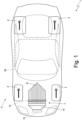
Figure 1 is a schematic view of a car that is realized in accordance with the present invention and that is provided with an aerodynamic sound generation system; -
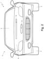
Figure 2 is a front view of the car ofFigure 1 ; -
Figure 3 is a schematic view of a single pipe of the aerodynamic sound generation system of the car ofFigure 1 ; -
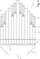
Figure 4 is a schematic view of the aerodynamic sound generation system of the car ofFigure 1 ; -
Figure 5 is a schematic view of a variant of the aerodynamic sound generation system of the car ofFigure 1 ; and -
Figure 6 is a schematic view of a different embodiment of a car that is realized in accordance with the present invention and that is provided with the aerodynamic sound generation system. - In
Figure 1 , thereference number 1 indicates, as a whole, a car (road vehicle) comprising a chassis, which supports (by means of corresponding suspensions) twofront wheels 2 and tworear wheels 2. - According to a preferred embodiment, the
rear wheels 2 and/or thefront wheels 2 receive a drive torque from an electric powertrain system (namely provided solely with at least one electric motor); alternatively, therear wheels 2 and/or thefront wheels 2 receive a drive torque from a hybrid powertrain system (namely provided with both at least one electric motor and at least one combustion engine) or from a thermal powertrain system (namely provided solely with a combustion engine). - As illustrated in
Figure 2 , the chassis is covered by abody 3 which covers a passenger compartment which is arranged between thefront wheels 2 and therear wheels 2 and is provided with (at least) two seats each designed to accommodate a corresponding occupant; namely there is always room in the passenger compartment for a driver to whom (at least) a passenger can be added (whose presence is obviously optional). Thebody 3 comprises, among other things, a front bumper, afront hood 4, and awindshield 5 which delimits the passenger compartment at the front. Laterally, thebody 4 has two sides that are provided with respective doors, each of which is equipped with a respective openable window. - The
car 1 further comprises a bottom wall 6 (illustrated inFigure 6 ), which, in use, faces a road surface and which is connected to the body 3 (i.e. thebody 3 extends upwards from the bottom wall 6). - As illustrated in
Figure 1 , thecar 1 comprises an aerodynamicsound generation system 7 which is configured to generate sounds making use solely of the head wind, namely the movement of air relative to thecar 1 generated by the forward movement of the car 1 (the head wind is zero when thecar 1 is stationary and is more intense, the greater the forward speed of the car 1). In other words, the aerodynamicsound generation system 7 has no moving elements actuated by a (for example electric) motor in order to transmit a movement or a pressure to the air intended for the sound generation and thus uses only and solely the head wind for the generation of sound (i.e. it uses solely the movement and the pressure possessed by the head wind). - The aerodynamic
sound generation system 7 comprises a plurality ofaerophone instruments 8, which are arranged in parallel side by side and into which part of the head wind is conveyed; namely the head wind is used in the aerodynamicsound generation system 7 to activate (excite) theaerophone instruments 8, which causes saidaerophone instruments 8 to generate sounds. Preferably, theaerophone instruments 8 are arranged side by side and are designed to generate sounds at differentiated frequencies in such a manner that the overall sound generated by the aerodynamicsound generation system 7 is a combination of sounds at different frequencies. - The
aerophone instruments 8 are devices capable of generating a sound in which air is the primary medium that is set in vibration and thereby produces the sound. In particular, theaerophone instruments 8 are of a resonant type (resonant aerophones) inasmuch as the vibrating air is contained in a cavity of theaerophone instrument 8. In the embodiment illustrated in the accompanying figures, theaerophone instruments 8 are shaped like organ pipes, while according to other embodiments not illustrated theaerophone instruments 8 may have a different shape. - As illustrated in
Figure 4 , each aerophone instrument 8 (i.e. each organ pipe) comprises atubular body 9 of a circular cross-section, which has an inlet opening 10 at one end and is closed at the opposite end (i.e. is plugged by having a closing wall). Thetubular body 9 has an outlet opening 11 laterally (also referred to as "mouth"). In use, the air is introduced into thetubular body 9 through the inlet opening 10 and exits thetubular body 9 through the outlet opening 11; in this passage, the particular internal shape of thetubular body 9 causes the air inside thetubular body 9 to vibrate, thereby generating a sound whose intensity depends on the diameter (width) of thetubular body 9 and on the flow rate of air passing through thetubular body 9 and whose frequency depends on the length of thetubular body 9. - The aerodynamic
sound generation system 7 comprises theaerophone instruments 8 and a feeding device for conveying part of the head wind into eachaerophone instrument 8. In particular, in eachaerophone instrument 8 air is the primary medium that is set in vibration, thereby producing the sound, and eachaerophone instrument 8 has a cavity intended to contain the vibrating air. - As illustrated in
Figure 1 , the aerodynamicsound generation system 7 comprises anair intake 12, which is configured to intercept part of the head wind, and afeeding duct 13, which originates from theair intake 12 and leads to theinlet openings 10 of theaerophone instrument 8. - In the embodiment illustrated in
Figures 1 ,2 and3 , theair intake 12 is obtained through thebody 3, namely it is essentially a "hole" in thebody 3; in this embodiment, thefeeding duct 13 continues downstream of theaerophone instruments 8 from theoutlet openings 11 of theaerophone instruments 8 and ends in a release opening 14 through which the air having previously entered thefeeding duct 13 through theair intake 12 exits saidfeeding duct 13. The release opening 14 is also obtained through thebody 3, namely it is essentially a "hole" in thebody 3 and is arranged (longitudinally) downstream of theair intake 12. - In other words, the
feeding duct 13 extends from theair intake 12 obtained through thebody 3 to the release opening 14 obtained through thebody 3 downstream of theair intake 12 and is connected to theinlet openings 10 of theaerophone instruments 8 and to theoutlet openings 11 of theaerophone instruments 8. - In the embodiment illustrated in
Figures 1 ,2 and3 , the aerodynamicsound generation system 7, and in particular theaerophone instruments 8 of the aerodynamicsound generation system 7, is arranged underneath thefront hood 4; preferably (as best illustrated inFigure 2 ), both theair intake 12 and the release opening 14 are obtained through thefront hood 4. - According to a possible embodiment illustrated in
Figure 3 , aradiator 15 is provided, namely an air-liquid heat exchanger, which is arranged along thefeeding duct 13 upstream or downstream of theaerophone instrument 8.Figure 3 shows both possible arrangements of theradiator 15, but obviously asingle radiator 15 can be present along thefeeding duct 13. Arranging theradiator 15 upstream of theaerophone instruments 8 prioritizes the cooling function over the sound-generating function, while arranging theradiator 15 downstream of theaerophone instruments 8 prioritizes the sound-generating function over the cooling function. According to a different embodiment not illustrated, thefeeding duct 13 does not house aradiator 15. - According to a possible embodiment illustrated in
Figure 3 , aradiator 16 is provided, namely an air-liquid heat exchanger, which is included in theaerophone instruments 8; namely theradiator 16 is inserted inside thetubular body 9 of eachaerophone instrument 8 and is arranged between the inlet opening 10 and the outlet opening 11 in such a manner that it is hit by the air flow passing through thetubular body 9. - As illustrated in
Figure 3 , eachaerophone instrument 8 comprises anadjustment body 17, which is mounted in a movable manner in theaerophone instrument 8 so as to change the frequency of a sound generated by saidaerophone instrument 8. In particular, theadjustment body 17 is a plunger axially moving inside thetubular body 9 of theaerophone instrument 8 so as to vary the length of the volume of vibrating air and thus vary the frequency of the sound generated by the vibration of the air (the greater the length of the volume of vibrating air is, the greater the wavelength of the sound and thus the lower the frequency of the sound generated by the vibration of the air). According to a preferred embodiment, eachaerophone instrument 8 comprises anelastic element 18, which is configured to push theadjustment body 17 towards a forward position (closer to the outlet opening 11) and is configured to be compressed by the pneumatic thrust exerted by the air upon theadjustment body 17 so as to allow theadjustment body 17 to reach a rearward position. The useful length of eachaerophone instrument 8 thus increases as the flow rate and the pressure of the air entering theaerophone instrument 8 increase, so that the frequency of the sound emitted by eachaerophone instrument 8 decreases as the flow rate and the pressure of the air entering theaerophone instrument 8 increase. - According to a possible embodiment illustrated in
Figures 3 and4 , only a part of theaerophone instruments 8 is provided with an adjustment body 17 (i.e. is capable of generating sounds at variable frequencies), and the remaining part of theaerophone instruments 8 is without an adjustment body 17 (i.e. always generates sounds at constant frequencies). According to one variant, the movement of theadjustment bodies 17 does not occur passively by exploiting the pneumatic thrust exerted by the air, but actively by means of an electronically controlled motorized actuator. According to a different embodiment that is not illustrated, allaerophone instruments 8 are without anadjustment body 17 and thus always generate sounds at constant frequencies. - As illustrated in
Figure 3 , the aerodynamicsound generation system 7 comprises, for eachaerophone instrument 8, anadjustment valve 19, preferably active and motorized, which is coupled to the inlet opening 10 of theaerophone instrument 8 and is configured to choke the inlet opening 10 of theaerophone instrument 8. By varying the degree of opening of theadjustment valve 19, it is possible to adjust the flow rate of air entering thecorresponding aerophone instrument 8, so that it is possible to adjust the intensity of the sound generated by theaerophone instrument 8. Alternatively, only a part of theaerophone instruments 8 are provided with theadjustment valve 19, or none of theaerophone instruments 8 are provided with theadjustment valve 19. - In the embodiment illustrated in
Figure 4 , adedicated adjustment valve 19 is provided for eachaerophone instrument 8. In the embodiment illustrated inFigure 5 , a single adjustment valve 19 (clearly larger and arranged near the air intake 12) common to allaerophone instruments 8 is provided. - In the embodiment illustrated in
Figure 4 , eachadjustment valve 19 is preferably active and motorized; in the embodiment illustrated inFigure 5 , the singlecommon adjustment valve 19 can either be active and motorized (according to a variant not illustrated) or it can be passive and thus without motorized actuators (according toFigure 5 ) . - As illustrated in
Figure 5 , theadjustment valve 19 comprises apipe 20 having aninlet opening 21, which is axially arranged and faces theair intake 12, and a plurality ofoutlet openings 22, which are radially arranged; in addition, theadjustment valve 19 comprises aplunger 23 mounted so as to move inside the pipe 20 (translate, slide) between a complete closing position, in which theplunger 23 is arranged between theinlet opening 10 and the outlet openings 22 (thereby preventing air from passing through theoutlet openings 22, which are thus completely insulated from the air intake 12), and a complete opening position, in which theplunger 23 is not arranged between theinlet opening 10 and all the outlet openings 22 (thereby allowing air to pass through all theoutlet openings 22, which are thus all connected by the air intake 12). Obviously, theplunger 15 can also assume intermediate positions that are located between the complete closing position and the complete opening position and that determine the isolation of only part of theoutlet openings 22. Theadjustment valve 19 finally comprises anelastic element 18 configured to push theplunger 23 towards theinlet opening 10 and towards the complete closing position and configured to be compressed by the pneumatic thrust exerted by the air upon theplunger 23 so as to allow theplunger 23 to reach a complete opening position. - The flow rate of air arriving at the
inlet openings 10 of theaerophone instruments 8 thus increases as the flow rate and the pressure of the air arriving from theair intake 12 increase, so that the intensity of the sound emitted by theaerophone instruments 8 increases as the flow rate and the pressure of the air arriving from theair intake 12 increase. - In the embodiment illustrated in
Figures 1 ,2 and3 , theair intake 12 is obtained through thebody 3, so that the aerodynamicsound generation system 7 is arranged inside thebody 3; in the embodiment illustrated inFigure 6 , on the other hand, the aerodynamicsound generation system 7 is fixed to thebottom wall 6 of thecar 1, so that it protrudes in a cantilevered manner from saidbottom wall 6. According to a further embodiment not illustrated, theair intake 12 is obtained through thebottom wall 6 of thecar 1, so that the aerodynamicsound generation system 7 is arranged immediately behind thebottom wall 6, namely the aerodynamicsound generation system 7 is arranged between thebottom wall 6 and a floor of thecar 1. In this embodiment, the feedingduct 13 generally ends at theinlet openings 10 of theaerophone instruments 8 and theinlet openings 11 of theaerophone instruments 8 lead directly into the outside environment. - According to a possible embodiment, the
car 1 comprises a power storage system 25 (schematically illustrated inFigure 1 ) which is part of thebottom wall 6 and supports theaerophone instrument 8; this embodiment can be combined with the presence of aradiator 16 included in one or more of theaerophone instruments 8 for cooling thestorage system 25. - According to a possible embodiment, the aerodynamic
sound generation system 7 could also comprise a compressor (actuated by a dedicated electric motor) that generates an additional air flow in addition to the flow of air entering from theair intake 12 when thecar 1 advances at a moderate speed. - The embodiments described here can be combined with one another without departing from the scope of protection of the present invention.
- The
car 1 described above provided with the aerodynamicsound generation system 7 exhibits numerous advantages. - First of all, the
car 1 described above makes it possible to generate a sound when driven that is "pleasant" (i.e. corresponds to the expectations of a driver of a high-performance sports car), is completely natural (i.e. originates completely from physical phenomena that occur due to the motion of the car and is not the result of a digital sound reproduced by loudspeakers), and varies autonomously as the forward speed of thecar 1 varies. In particular, the sound generated by the movement of thecar 1 can vary as the forward speed of thecar 1 varies, both in intensity (which increases as the forward speed of thecar 1 increases) and pitch (generally the overall pitch of the sound is higher at reduced speeds and lower at high speeds). - Moreover, variations in the sound generated by the movement of the
car 1 as the forward speed of thecar 1 varies can be achieved solely with passive actuators (which use theelastic elements 18 and 24), which are thus lighter, more compact, do not require a power supply, and are much less prone to malfunctioning. - Finally, the
car 1 described in the foregoing is simple and inexpensive to realize, as the aerodynamicsound generation system 7 is not too bulky and can be accommodated in spaces that are normally free and unused (in a high-performance sports car). The realization of the aerodynamicsound generation system 7 is also simple and inexpensive on the whole, inasmuch as it essentially consists of metal pipes with walls of a small thickness (having no structural function and only having to withstand the thrust of the head wind). -
- 1
- car
- 2
- wheels
- 3
- body
- 4
- front hood
- 5
- windshield
- 6
- bottom wall
- 7
- aerodynamic sound generation system
- 8
- aerophone instrument
- 9
- tubular body
- 10
- inlet opening
- 11
- outlet opening
- 12
- air intake
- 13
- feeding duct
- 14
- release opening
- 15
- radiator
- 16
- radiator
- 17
- adjustment body
- 18
- elastic element
- 19
- adjustment valve
- 20
- pipe
- 21
- inlet opening
- 22
- outlet opening
- 23
- plunger
- 24
- elastic element
- 25
- power storage system
Claims (19)
- A road vehicle (1) comprising:a bottom wall (6) which, in use, faces a road surface;a body (3) which delimits a passenger compartment; andan aerodynamic sound generation system (7);the road vehicle (1) is characterized in that:the aerodynamic sound generation system (7) is configured to generate sounds making use solely of the action of the head wind, namely the movement of air relative to the road vehicle (1) generated by the forward movement of the road vehicle (1); andthe aerodynamic sound generation system (7) comprises at least one aerophone instrument (8) and a feeding device for conveying part of the head wind into the aerophone instrument (8).
- The road vehicle (1) according to claim 1, wherein in the aerophone instrument (8) air is the primary medium that is set in vibration, thereby producing the sound, and the aerophone instrument (8) has a cavity intended to contain the vibrating air.
- The road vehicle (1) according to claim 1 or 2, wherein the feeding device of the aerodynamic sound generation system (7) comprises an air intake (12), which is configured to intercept part of the head wind, and a feeding duct (13), which originates from the air intake (12) and leads to an inlet opening (10) of the aerophone instrument (8) .
- The road vehicle (1) according to claim 3, wherein the aerodynamic sound generation system (7) comprises an adjustment valve (19), which is coupled to the inlet opening (10) of the aerophone instrument (8) and is configured to choke the inlet opening (10) of the aerophone instrument (8) .
- The road vehicle (1) according to claim 3, wherein the aerodynamic sound generation system (7) comprises an adjustment valve (19), which is coupled to the feeding duct (13) and is configured to choke the passage of air along the feeding duct (13).
- The road vehicle (1) according to claim 5, wherein the adjustment valve (19) comprises:a pipe (20) having an inlet opening (21), which is axially arranged and faces the air intake (12), and a plurality of outlet openings (22), which are radially arranged;a plunger (23) mounted so as to move inside the pipe (20); andan elastic element (24) configured to push the plunger (23) towards the inlet opening (10) and towards a complete closing position, in which the plunger (23) is arranged between the inlet opening (10) and the outlet openings (22), and configured to be compressed by the pneumatic thrust exerted by the air upon the plunger (23) so as to allow the plunger (23) to reach a complete opening position, in which the plunger (23) is not arranged between the inlet opening (10) and the outlet openings (22).
- The road vehicle (1) according to one of the claims from 3 to 6, wherein the air intake (12) is obtained through the body (3).
- The road vehicle (1) according to claim 7, wherein the aerophone instrument (8) is arranged under a front hood (4) .
- The road vehicle (1) according to one of the claims from 3 to 8, wherein the feeding duct (13) extends from the air intake (12) obtained through the body (3) to a release opening (14) obtained through the body (3) downstream of the air intake (12) and is connected to the inlet opening (10) of the aerophone instrument (8) and to an outlet opening (11) of the aerophone instrument (8).
- The road vehicle (1) according to claim 9 and comprising a radiator (15), namely an air-liquid heat exchanger, which is arranged along the feeding duct (13) upstream or downstream of the aerophone instrument (8).
- The road vehicle (1) according to claim 9 and comprising a radiator (16), namely an air-liquid heat exchanger, which is included in the aerophone instrument (8) .
- The road vehicle (1) according to one of the claims from 3 to 6, wherein the air intake (12) is obtained through the bottom wall (6).
- The road vehicle (1) according to one of the claims from 3 to 6, wherein the aerophone instrument (8) is fixed to the bottom wall (6).
- The road vehicle (1) according to claim 12 or 13 and comprising a power storage system (25), which is part of the bottom wall (6) and supports the aerophone instrument (8) .
- The road vehicle (1) according to one of the claims from 1 to 14, wherein the aerophone instrument (8) comprises an adjustment body (17), which is mounted in a movable manner in the aerophone instrument (8) so as to change the frequency of a sound generated by the aerophone instrument (8).
- The road vehicle (1) according to claim 15, wherein the aerophone instrument (8) comprises an elastic element (18), which is configured to push the adjustment body (17) towards a first position and is configured to be compressed by the pneumatic thrust exerted by the air upon the adjustment body (17) so as to allow the adjustment body (17) to reach a second position.
- The road vehicle (1) according to claim 16, wherein the adjustment body (17) is a plunger axially moving inside the aerophone instrument (8).
- The road vehicle (1) according to one of the claims from 1 to 17, wherein the aerophone instrument (8) is shaped like an organ pipe.
- The road vehicle (1) according to one of the claims from 1 to 18, wherein the aerodynamic sound generation system (7) comprises a plurality of aerophone instruments (8), which are arranged side by side and are designed to generate sounds at different frequencies.
Applications Claiming Priority (1)
| Application Number | Priority Date | Filing Date | Title |
|---|---|---|---|
| IT102022000019332A IT202200019332A1 (en) | 2022-09-21 | 2022-09-21 | ROAD VEHICLE EQUIPPED WITH AN AERODYNAMIC SOUND GENERATION SYSTEM |
Publications (2)
| Publication Number | Publication Date |
|---|---|
| EP4343751A1 true EP4343751A1 (en) | 2024-03-27 |
| EP4343751B1 EP4343751B1 (en) | 2026-04-29 |
Family
ID=88020717
Family Applications (1)
| Application Number | Title | Priority Date | Filing Date |
|---|---|---|---|
| EP23198572.2A Active EP4343751B1 (en) | 2022-09-21 | 2023-09-20 | Road vehicle provided with an aerodynamic sound generation system |
Country Status (5)
| Country | Link |
|---|---|
| US (1) | US12344164B2 (en) |
| EP (1) | EP4343751B1 (en) |
| JP (1) | JP2024045052A (en) |
| CN (1) | CN117734570A (en) |
| IT (1) | IT202200019332A1 (en) |
Families Citing this family (1)
| Publication number | Priority date | Publication date | Assignee | Title |
|---|---|---|---|---|
| IT202200019332A1 (en) * | 2022-09-21 | 2024-03-21 | Ferrari Spa | ROAD VEHICLE EQUIPPED WITH AN AERODYNAMIC SOUND GENERATION SYSTEM |
Citations (3)
| Publication number | Priority date | Publication date | Assignee | Title |
|---|---|---|---|---|
| WO2009140289A2 (en) | 2008-05-12 | 2009-11-19 | Ballard Claudio R | Electrically propelled vehicle having electric sound-producing blower/cooler |
| US20130036892A1 (en) * | 2010-04-02 | 2013-02-14 | Denys Delporte | Set of organ pipes |
| US20180244212A1 (en) * | 2015-08-28 | 2018-08-30 | Pioneer Corporation | Speaker system for mobile object |
Family Cites Families (25)
| Publication number | Priority date | Publication date | Assignee | Title |
|---|---|---|---|---|
| US8537030B2 (en) * | 2010-02-15 | 2013-09-17 | Ford Global Technologies, Llc | Pedestrian alert system and method |
| US9814999B2 (en) * | 2014-08-22 | 2017-11-14 | Rohan Shaanti | Aerophone builder |
| ITUB20159781A1 (en) * | 2015-01-13 | 2017-06-30 | Ask Ind Spa | ENGINE SOUND ENHANCEMENT SYSTEM IN A VEHICLE. |
| KR101673761B1 (en) * | 2015-04-22 | 2016-11-07 | 현대자동차주식회사 | Aero parts of vehicle having virtual engine sound generation function |
| WO2016177380A1 (en) * | 2015-05-07 | 2016-11-10 | Nyenstad Mønster Dan | Wiperless cleaning system for transparent surfaces using air jets |
| WO2017125990A1 (en) * | 2016-01-22 | 2017-07-27 | パナソニックIpマネジメント株式会社 | Vehicle approach notification device |
| KR101804772B1 (en) * | 2016-08-25 | 2017-12-05 | 현대자동차주식회사 | Sound control apparatus, vehicle and method of controlling thereof |
| DE102016219485A1 (en) * | 2016-10-07 | 2018-04-12 | Audi Ag | Motor vehicle and energy storage device |
| JP6743684B2 (en) * | 2016-12-22 | 2020-08-19 | トヨタ紡織株式会社 | Vehicle seat blower and vehicle seat |
| DE102018218520A1 (en) * | 2018-10-30 | 2020-04-30 | Volkswagen Aktiengesellschaft | Arrangement of an air guide element made of foam on a cooler element and cooler element and air guide element made of foam |
| JP7147639B2 (en) * | 2019-03-13 | 2022-10-05 | 株式会社デンソーエレクトロニクス | audio output device |
| US11451168B2 (en) * | 2019-05-23 | 2022-09-20 | Shihyu Lu | Strain-relieved compliant structures for flextensional transduction |
| US11733960B1 (en) * | 2019-11-15 | 2023-08-22 | Zoox, Inc. | Vehicle warning signal emission |
| US11257477B2 (en) * | 2020-03-18 | 2022-02-22 | Harman International Industries, Incorporated | Motor noise masking |
| DE102020112871A1 (en) * | 2020-05-12 | 2021-11-18 | Bayerische Motoren Werke Aktiengesellschaft | Motor vehicle with an acoustic device for generating and capturing audible sound |
| KR102739215B1 (en) * | 2020-06-04 | 2024-12-05 | 현대자동차주식회사 | Method of Voice Control Based on Motor Vibration of EV |
| EP4214699A4 (en) * | 2020-09-17 | 2024-09-25 | Orb Music Inc. | AEROPHONE USING AN OBJECT FILLED WITH AIR |
| KR102804893B1 (en) * | 2020-09-28 | 2025-05-09 | 현대자동차주식회사 | Method of Voice Control Based on Motor Vibration of EV in Reduction of Velocity and Regeneration of Brake |
| KR102842412B1 (en) * | 2020-10-20 | 2025-08-06 | 현대자동차주식회사 | Vehicle and method for controlling thereof |
| GB2602007A (en) * | 2020-12-14 | 2022-06-22 | Pss Belgium Nv | Vehicle warning system |
| KR102854831B1 (en) * | 2021-02-22 | 2025-09-04 | 현대자동차주식회사 | Apparaus for outputting virtual engine sound |
| KR20230137104A (en) * | 2022-03-21 | 2023-10-04 | 현대자동차주식회사 | Apparatus and method for generating virtual sound |
| IT202200019332A1 (en) * | 2022-09-21 | 2024-03-21 | Ferrari Spa | ROAD VEHICLE EQUIPPED WITH AN AERODYNAMIC SOUND GENERATION SYSTEM |
| KR20240097174A (en) * | 2022-12-20 | 2024-06-27 | 현대모비스 주식회사 | engine sound generating system, and engine sound generating method |
| IT202300007728A1 (en) * | 2023-04-20 | 2024-10-20 | Ferrari Spa | MOTOR VEHICLE EQUIPPED WITH AN AERODYNAMIC SOUND GENERATION DEVICE |
-
2022
- 2022-09-21 IT IT102022000019332A patent/IT202200019332A1/en unknown
-
2023
- 2023-09-19 JP JP2023150660A patent/JP2024045052A/en active Pending
- 2023-09-20 EP EP23198572.2A patent/EP4343751B1/en active Active
- 2023-09-20 US US18/470,499 patent/US12344164B2/en active Active
- 2023-09-20 CN CN202311216479.8A patent/CN117734570A/en active Pending
Patent Citations (3)
| Publication number | Priority date | Publication date | Assignee | Title |
|---|---|---|---|---|
| WO2009140289A2 (en) | 2008-05-12 | 2009-11-19 | Ballard Claudio R | Electrically propelled vehicle having electric sound-producing blower/cooler |
| US20130036892A1 (en) * | 2010-04-02 | 2013-02-14 | Denys Delporte | Set of organ pipes |
| US20180244212A1 (en) * | 2015-08-28 | 2018-08-30 | Pioneer Corporation | Speaker system for mobile object |
Also Published As
| Publication number | Publication date |
|---|---|
| JP2024045052A (en) | 2024-04-02 |
| US20240092261A1 (en) | 2024-03-21 |
| CN117734570A (en) | 2024-03-22 |
| EP4343751B1 (en) | 2026-04-29 |
| US12344164B2 (en) | 2025-07-01 |
| IT202200019332A1 (en) | 2024-03-21 |
Similar Documents
| Publication | Publication Date | Title |
|---|---|---|
| CN103144534B (en) | Engine packaging cover structure of vehicle | |
| EP4343751A1 (en) | Road vehicle provided with an aerodynamic sound generation system | |
| CN112440677B (en) | Blade group structure, air conditioner air outlet structure of vehicle and vehicle | |
| US7686130B1 (en) | Dual mode vehicle exhaust system and associated method | |
| US20090277707A1 (en) | Electrically propelled vehicle having electric sound-producing blower/cooler | |
| KR20190142636A (en) | Virtual engine sound system for vehicle | |
| CN215705567U (en) | A hidden electric air outlet system | |
| CN108025631B (en) | Vehicle with double flow exhaust | |
| WO2019230089A1 (en) | Heating system for vehicle interior | |
| CN108621741B (en) | Alternately operable air duct with blocking member for driver-only functions | |
| EP2315680B1 (en) | System for using the air pressure acting on a vehicle in motion to produce energy | |
| JP2006022803A (en) | Variable intake system of automobile | |
| US20070169991A1 (en) | Device and method for heat and noise insulation of motor vehicles | |
| KR101388621B1 (en) | Battery pack unit | |
| KR20170041059A (en) | Front End Module | |
| JP2011098703A (en) | Air conditioner and battery cooling system for electric vehicle | |
| CN111845324B (en) | Cooling air supply device for a motor vehicle | |
| CN110576915B (en) | Active front spoiler device for vehicle | |
| JP2002254924A (en) | Cooling structure in the trunk room of a car | |
| CN114687844B (en) | Automobile provided with exhaust system with pneumatic effect | |
| US4709855A (en) | Recirculating heating system | |
| JP2009292328A (en) | Temperature adjusting mechanism | |
| EP1716010A2 (en) | Air duct outlets having return air passageways that facilitate oscillating air flow | |
| CN116442876B (en) | Vehicle headrest, vehicle seat, vehicle and silencing method for silencing | |
| JPH0748983Y2 (en) | Engine intake system |
Legal Events
| Date | Code | Title | Description |
|---|---|---|---|
| PUAI | Public reference made under article 153(3) epc to a published international application that has entered the european phase |
Free format text: ORIGINAL CODE: 0009012 |
|
| STAA | Information on the status of an ep patent application or granted ep patent |
Free format text: STATUS: THE APPLICATION HAS BEEN PUBLISHED |
|
| AK | Designated contracting states |
Kind code of ref document: A1 Designated state(s): AL AT BE BG CH CY CZ DE DK EE ES FI FR GB GR HR HU IE IS IT LI LT LU LV MC ME MK MT NL NO PL PT RO RS SE SI SK SM TR |
|
| STAA | Information on the status of an ep patent application or granted ep patent |
Free format text: STATUS: REQUEST FOR EXAMINATION WAS MADE |
|
| 17P | Request for examination filed |
Effective date: 20240405 |
|
| RBV | Designated contracting states (corrected) |
Designated state(s): AL AT BE BG CH CY CZ DE DK EE ES FI FR GB GR HR HU IE IS IT LI LT LU LV MC ME MK MT NL NO PL PT RO RS SE SI SK SM TR |
|
| GRAP | Despatch of communication of intention to grant a patent |
Free format text: ORIGINAL CODE: EPIDOSNIGR1 |
|
| STAA | Information on the status of an ep patent application or granted ep patent |
Free format text: STATUS: GRANT OF PATENT IS INTENDED |
|
| RIC1 | Information provided on ipc code assigned before grant |
Ipc: G10B 1/02 20060101AFI20251112BHEP Ipc: G10K 11/04 20060101ALI20251112BHEP Ipc: G10K 15/04 20060101ALI20251112BHEP Ipc: G10B 3/08 20060101ALI20251112BHEP Ipc: G10K 5/00 20060101ALN20251112BHEP |
|
| INTG | Intention to grant announced |
Effective date: 20251128 |
|
| GRAS | Grant fee paid |
Free format text: ORIGINAL CODE: EPIDOSNIGR3 |
|
| GRAA | (expected) grant |
Free format text: ORIGINAL CODE: 0009210 |
|
| STAA | Information on the status of an ep patent application or granted ep patent |
Free format text: STATUS: THE PATENT HAS BEEN GRANTED |
|
| AK | Designated contracting states |
Kind code of ref document: B1 Designated state(s): AL AT BE BG CH CY CZ DE DK EE ES FI FR GB GR HR HU IE IS IT LI LT LU LV MC ME MK MT NL NO PL PT RO RS SE SI SK SM TR |
|
| REG | Reference to a national code |
Ref country code: CH Ref legal event code: F10 Free format text: ST27 STATUS EVENT CODE: U-0-0-F10-F00 (AS PROVIDED BY THE NATIONAL OFFICE) Effective date: 20260429 |