EP4343385A1 - Wind speed prediction device, wind speed prediction method, and radar device - Google Patents
Wind speed prediction device, wind speed prediction method, and radar device Download PDFInfo
- Publication number
- EP4343385A1 EP4343385A1 EP21946946.7A EP21946946A EP4343385A1 EP 4343385 A1 EP4343385 A1 EP 4343385A1 EP 21946946 A EP21946946 A EP 21946946A EP 4343385 A1 EP4343385 A1 EP 4343385A1
- Authority
- EP
- European Patent Office
- Prior art keywords
- wind speed
- unit
- speed distribution
- dimensional plane
- dimensional
- Prior art date
- Legal status (The legal status is an assumption and is not a legal conclusion. Google has not performed a legal analysis and makes no representation as to the accuracy of the status listed.)
- Granted
Links
Images




Classifications
-
- G—PHYSICS
- G01—MEASURING; TESTING
- G01S—RADIO DIRECTION-FINDING; RADIO NAVIGATION; DETERMINING DISTANCE OR VELOCITY BY USE OF RADIO WAVES; LOCATING OR PRESENCE-DETECTING BY USE OF THE REFLECTION OR RERADIATION OF RADIO WAVES; ANALOGOUS ARRANGEMENTS USING OTHER WAVES
- G01S17/00—Systems using the reflection or reradiation of electromagnetic waves other than radio waves, e.g. lidar systems
- G01S17/88—Lidar systems specially adapted for specific applications
- G01S17/95—Lidar systems specially adapted for specific applications for meteorological use
-
- G—PHYSICS
- G01—MEASURING; TESTING
- G01S—RADIO DIRECTION-FINDING; RADIO NAVIGATION; DETERMINING DISTANCE OR VELOCITY BY USE OF RADIO WAVES; LOCATING OR PRESENCE-DETECTING BY USE OF THE REFLECTION OR RERADIATION OF RADIO WAVES; ANALOGOUS ARRANGEMENTS USING OTHER WAVES
- G01S13/00—Systems using the reflection or reradiation of radio waves, e.g. radar systems; Analogous systems using reflection or reradiation of waves whose nature or wavelength is irrelevant or unspecified
- G01S13/88—Radar or analogous systems specially adapted for specific applications
- G01S13/95—Radar or analogous systems specially adapted for specific applications for meteorological use
-
- G—PHYSICS
- G01—MEASURING; TESTING
- G01S—RADIO DIRECTION-FINDING; RADIO NAVIGATION; DETERMINING DISTANCE OR VELOCITY BY USE OF RADIO WAVES; LOCATING OR PRESENCE-DETECTING BY USE OF THE REFLECTION OR RERADIATION OF RADIO WAVES; ANALOGOUS ARRANGEMENTS USING OTHER WAVES
- G01S17/00—Systems using the reflection or reradiation of electromagnetic waves other than radio waves, e.g. lidar systems
- G01S17/02—Systems using the reflection of electromagnetic waves other than radio waves
- G01S17/50—Systems of measurement based on relative movement of target
- G01S17/58—Velocity or trajectory determination systems; Sense-of-movement determination systems
-
- G—PHYSICS
- G01—MEASURING; TESTING
- G01S—RADIO DIRECTION-FINDING; RADIO NAVIGATION; DETERMINING DISTANCE OR VELOCITY BY USE OF RADIO WAVES; LOCATING OR PRESENCE-DETECTING BY USE OF THE REFLECTION OR RERADIATION OF RADIO WAVES; ANALOGOUS ARRANGEMENTS USING OTHER WAVES
- G01S7/00—Details of systems according to groups G01S13/00, G01S15/00, G01S17/00
- G01S7/48—Details of systems according to groups G01S13/00, G01S15/00, G01S17/00 of systems according to group G01S17/00
- G01S7/4808—Evaluating distance, position or velocity data
-
- G—PHYSICS
- G01—MEASURING; TESTING
- G01W—METEOROLOGY
- G01W1/00—Meteorology
- G01W1/10—Devices for predicting weather conditions
-
- G—PHYSICS
- G01—MEASURING; TESTING
- G01S—RADIO DIRECTION-FINDING; RADIO NAVIGATION; DETERMINING DISTANCE OR VELOCITY BY USE OF RADIO WAVES; LOCATING OR PRESENCE-DETECTING BY USE OF THE REFLECTION OR RERADIATION OF RADIO WAVES; ANALOGOUS ARRANGEMENTS USING OTHER WAVES
- G01S17/00—Systems using the reflection or reradiation of electromagnetic waves other than radio waves, e.g. lidar systems
- G01S17/02—Systems using the reflection of electromagnetic waves other than radio waves
- G01S17/06—Systems determining position data of a target
- G01S17/42—Simultaneous measurement of distance and other co-ordinates
-
- Y—GENERAL TAGGING OF NEW TECHNOLOGICAL DEVELOPMENTS; GENERAL TAGGING OF CROSS-SECTIONAL TECHNOLOGIES SPANNING OVER SEVERAL SECTIONS OF THE IPC; TECHNICAL SUBJECTS COVERED BY FORMER USPC CROSS-REFERENCE ART COLLECTIONS [XRACs] AND DIGESTS
- Y02—TECHNOLOGIES OR APPLICATIONS FOR MITIGATION OR ADAPTATION AGAINST CLIMATE CHANGE
- Y02A—TECHNOLOGIES FOR ADAPTATION TO CLIMATE CHANGE
- Y02A90/00—Technologies having an indirect contribution to adaptation to climate change
- Y02A90/10—Information and communication technologies [ICT] supporting adaptation to climate change, e.g. for weather forecasting or climate simulation
Definitions
- the present disclosure relates to a wind speed prediction device, a wind speed prediction method, and a radar device.
- Some wind speed prediction devices that predict a wind speed in an observation region include a wind speed prediction device (hereinafter referred to as a "conventional wind speed prediction device”) that predicts a wind speed in an observation region by simulating the wind speed using a weather model (see Patent Literature 1).
- the simulation of the wind speed is three-dimensional calculation processing.
- Patent Literature 1 Japanese Patent Application Laid-Open No. 2014-202190
- the conventional wind speed prediction device disclosed in Patent Literature 1 performs three-dimensional calculation processing, and thus has a problem that a calculation load may increase.
- the present disclosure has been made to solve the above problems, and an object thereof is to obtain a wind speed prediction device and a wind speed prediction method capable of predicting a wind speed without performing three-dimensional calculation processing.
- a wind speed prediction device includes a scattering signal acquiring unit to acquire a scattering signal that is each of a plurality of beams after being emitted to space and scattered in the space, the beams having mutually different elevation angles, which are angles formed by a line-of-sight direction and a horizontal direction, a Doppler frequency calculating unit to set a range bin width as distance resolution of each of scattering signals acquired by the scattering signal acquiring unit in accordance with an elevation angle of each of the beams emitted to the space, and calculate a Doppler frequency of a range bin corresponding to a two-dimensional plane including an observation region from the each of the scattering signals, a first wind speed distribution estimating unit to estimate a wind speed distribution in the two-dimensional plane from a plurality of Doppler frequencies calculated by the Doppler frequency calculating unit using a volume velocity processing (VVP) method, and a wind speed prediction unit to predict a wind speed in the observation region from the wind speed distribution in the two-dimensional plane estimated by the first
- VVP
- a wind speed can be predicted without performing three-dimensional calculation processing.
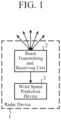
- FIG. 1 is a configuration diagram illustrating a radar device 1 including a wind speed prediction device 3 according to a first embodiment.
- the radar device 1 illustrated in FIG. 1 includes a beam transmitting and receiving unit 2 and a wind speed prediction device 3.
- FIG. 2 is an explanatory diagram illustrating a plurality of beams emitted to space from the beam transmitting and receiving unit 2.
- the observation region is present in the space.
- the observation region is, for example, a flight area in which a flying object is scheduled to fly.
- the flying object is, for example, a drone or a helicopter.
- FIG. 2A is an explanatory diagram illustrating a plurality of beams in a case where the position of the flight area is directly above the beam transmitting and receiving unit 2 in the vertical direction.
- FIG. 2B is an explanatory diagram illustrating a plurality of beams in a case where the position of the flight area is deviated from directly above the beam transmitting and receiving unit 2 in the vertical direction.
- the beam transmitting and receiving unit 2 includes, for example, a beam generating unit, a beam transmitter, a radiation direction switching unit, an antenna, and a beam receiver.
- a beam generating unit for example, a beam generating unit, a beam transmitter, a radiation direction switching unit, an antenna, and a beam receiver.
- notations of the beam generating unit, the beam transmitter, the radiation direction switching unit, the antenna, and the beam receiver are omitted.
- N is an integer of 2 or more.
- the beam transmitting and receiving unit 2 when the flight area is present directly above in the vertical direction, the beam transmitting and receiving unit 2 emits beams in different directions at respective elevation angles ⁇ n by performing beam scanning at the respective elevation angles ⁇ n .
- N 3
- each of the beam with the elevation angle ⁇ 1 , the beam with the elevation angle ⁇ 2 , and the beam with the elevation angle ⁇ 3 is emitted from the beam transmitting and receiving unit 2 to space.
- beams are emitted in four directions at the respective elevation angles ⁇ n .
- black circles indicate observation points of the wind speed.
- the beam transmitting and receiving unit 2 when the position of the flight area is deviated from directly above in the vertical direction, the beam transmitting and receiving unit 2 emits beams at respective elevation angles ⁇ n while switching the elevation angles ⁇ n .
- N 12
- beams of elevation angles ⁇ 1 to ⁇ 12 are emitted from the beam transmitting and receiving unit 2 to space.
- the elevation angles ⁇ 1 to ⁇ 6 are illustrated in FIG. 2B , and the illustration of the elevation angles ⁇ 7 to ⁇ 12 is omitted.
- a beam is emitted in one direction at each elevation angle ⁇ n .
- black circles indicate observation points of the wind speed.
- FIGS. 2A and 2B illustrates an example of obtaining wind speed distributions in three two-dimensional planes. However, this is merely an example, and wind speed distributions in one or two two-dimensional planes may be obtained, or wind speed distributions in four or more two-dimensional planes may be obtained.
- the beam emitted from the beam transmitting and receiving unit 2 for example, in addition to continuous wave (CW) pulsed light, frequency-modulated pulsed light can be used.
- CW continuous wave
- the beam transmitting and receiving unit 2 receives each beam scattered in space as a scattering signal.
- the beam transmitting and receiving unit 2 converts each scattering signal from an analog signal to a digital signal, and outputs the digital signal to the wind speed prediction device 3.
- the beam transmitting and receiving unit 2 outputs angle information indicating the elevation angle ⁇ n of each beam emitted to space to the wind speed prediction device 3.
- the beam transmitting and receiving unit 2 includes a beam generating unit, a beam transmitter, a radiation direction switching unit, an antenna, and a beam receiver.
- the beam transmitting and receiving unit 2 is only required to emit each of a plurality of beams having different elevation angles ⁇ n into space and receive each beam scattered in the space as a scattering signal, and may have any configuration.
- FIG. 3 is a configuration diagram illustrating the wind speed prediction device 3 according to the first embodiment.
- FIG. 4 is a hardware configuration diagram illustrating hardware of the wind speed prediction device 3 according to the first embodiment.
- the wind speed prediction device 3 illustrated in FIG. 3 includes a scattering signal acquiring unit 11, a Doppler frequency calculating unit 12, a first wind speed distribution estimating unit 13, a second wind speed distribution estimating unit 14, and a wind speed prediction unit 15.
- the scattering signal acquiring unit 11 is implemented by, for example, a scattering signal acquiring circuit 21 illustrated in FIG. 4 .
- the scattering signal acquiring unit 11 acquires each of digital signals s ⁇ n,j (t) from the beam transmitting and receiving unit 2 as each of scattering signals after being scattered in space.
- j 1, ..., J.
- j is the scan number of beam scanning at the elevation angle ⁇ n .
- t is a variable indicating time.
- the scattering signal acquiring unit 11 acquires the angle information indicating the elevation angle ⁇ n of each beam emitted into space by the beam transmitting and receiving unit 2.
- the scattering signal acquiring unit 11 outputs each of the digital signals s ⁇ n,j (t) and the angle information to the Doppler frequency calculating unit 12.
- the Doppler frequency calculating unit 12 is implemented by, for example, a Doppler frequency calculating circuit 22 illustrated in FIG. 4 .
- the Doppler frequency calculating unit 12 acquires each of the digital signals s ⁇ n,j (t) and the angle information from the scattering signal acquiring unit 11.
- the Doppler frequency calculating unit 12 Before performing fast Fourier transformation (FFT) on each digital signal s ⁇ n,j (t) in the hit direction, the Doppler frequency calculating unit 12 sets a range bin width as the distance resolution of each digital signal s ⁇ n,j (t) according to the elevation angle ⁇ n indicated by the angle information. That is, the Doppler frequency calculating unit 12 sets an FFT length L ⁇ n corresponding to the range bin width.
- FFT fast Fourier transformation
- the FFT length L ⁇ n is set shorter as the elevation angle ⁇ n of the beam emitted to space is wider, and is set longer as the elevation angle ⁇ n of the beam emitted to the space is narrower.
- the FFT length L ⁇ 1 of the digital signal s ⁇ 1,j (t) corresponding to the beam at the elevation angle ⁇ 1 is longer than the FFT length L ⁇ 2 of the digital signal s ⁇ 2,j (t) corresponding to the beam at the elevation angle ⁇ 2
- the FFT length L ⁇ 2 of the digital signal s ⁇ 2,j (t) corresponding to the beam at the elevation angle ⁇ 2 is longer than the FFT length L ⁇ 3 of the digital signal s ⁇ 3,j (t) corresponding to the beam at the elevation angle ⁇ 3 .
- the Doppler frequency calculating unit 12 converts each of the digital signals s ⁇ n,j (t) into frequency domain signals r ⁇ n,j (f) by performing FFT on the digital signals s ⁇ n,j (t) acquired by the scattering signal acquiring unit 11 in the hit direction.
- f is a variable indicating a frequency.
- the Doppler frequency calculating unit 12 calculates the respective Doppler frequencies dpf ⁇ n,j,Rbm in a plurality of range bins Rbi to Rb M from the signals r ⁇ n,j (f) in the frequency domain.
- m 1, ..., M, and M is an integer of 1 or more.
- FIG. 2 illustrates an example of obtaining wind speed distributions in three two-dimensional planes.
- the Doppler frequency calculating unit 12 calculates the Doppler frequencies dpf ⁇ n,j,Rbm in the range bins Rb 1 , Rb 2 , and Rb 3 from the signals r ⁇ n,j (f) in the frequency domain.
- M is an integer of 2 or more.
- the Doppler frequency calculating unit 12 calculates only the Doppler frequency dpf ⁇ n,j,Rb1 of one range bin Rbi including the observation region from the frequency domain signal r ⁇ n,j (f).
- the Doppler frequency calculating unit 12 outputs the Doppler frequencies dpf ⁇ n,j,Rbm of the respective range bins Rb m to the first wind speed distribution estimating unit 13.
- the first wind speed distribution estimating unit 13 is implemented by, for example, a first wind speed distribution estimating circuit 23 illustrated in FIG. 4 .
- the first wind speed distribution estimating unit 13 estimates a wind speed distribution u Rbm (x, y) in a two-dimensional plane corresponding to each range bin Rb m using a volume velocity processing (VVP) method from a plurality of Doppler frequencies dpf ⁇ 1,j,Rbm to dpf ⁇ N,j,Rbm in each range bin Rb m calculated by the Doppler frequency calculating unit 12.
- VVP volume velocity processing
- the first wind speed distribution estimating unit 13 estimates the wind speed distribution u Rb1 (x, y) in the two-dimensional plane corresponding to the range bin Rbi as the two-dimensional plane including the observation region, and outputs the wind speed distribution u Rb1 (x, y) in the two-dimensional plane to the wind speed prediction unit 15.
- the first wind speed distribution estimating unit 13 When M is 2 or more, the first wind speed distribution estimating unit 13 outputs the wind speed distribution u Rbm (x, y) in the two-dimensional plane corresponding to each range bin Rb m to the second wind speed distribution estimating unit 14.
- the second wind speed distribution estimating unit 14 is implemented by, for example, a second wind speed distribution estimating circuit 24 illustrated in FIG. 4 .
- the second wind speed distribution estimating unit 14 estimates a wind speed distribution u Rbm' (x, y) in a two-dimensional plane between a plurality of two-dimensional planes from the wind speed distributions u Rb1 (x, y) to u RbM (x, y) in the plurality of two-dimensional planes estimated by the first wind speed distribution estimating unit 13.
- the wind speed distribution u Rb1' (x, y) in the two-dimensional plane is a wind speed distribution in the two-dimensional plane between the two-dimensional plane corresponding to the range bin Rbi and the two-dimensional plane corresponding to the range bin Rb 2 .
- the wind speed distribution u Rb2' (x, y) in the two-dimensional plane is a wind speed distribution in the two-dimensional plane between the two-dimensional plane corresponding to the range bin Rb 2 and the two-dimensional plane corresponding to the range bin Rb 3 .
- the second wind speed distribution estimating unit 14 outputs the wind speed distributions u Rb1' (x, y) to u RbM-1' (x, y) in the two-dimensional plane between the plurality of two-dimensional planes to the wind speed prediction unit 15.
- the wind speed prediction unit 15 is implemented by, for example, a wind speed prediction circuit 25 illustrated in FIG. 4 .
- the wind speed prediction unit 15 predicts a wind speed u(t) in the observation region from the wind speed distribution u Rb1 (x, y) in the two-dimensional plane estimated by the first wind speed distribution estimating unit 13 using the two-dimensional Navier-Stokes equation (hereinafter referred to as a "two-dimensional N-S equation").
- the observation region is, for example, an area including a flight area in which the flying object is scheduled to fly.
- the wind speed prediction unit 15 selects the wind speed distribution in the two-dimensional plane including the flight area as the observation region from the wind speed distributions u Rb1 (x, y) to u RbM (x, y) in the plurality of two-dimensional planes estimated by the first wind speed distribution estimating unit 13 and the wind speed distributions u Rb1' (x, y) to u RbM-1' (x, y) in the two-dimensional plane estimated by the second wind speed distribution estimating unit 14.
- the wind speed prediction unit 15 predicts the wind speed u(t) in the flight area from the wind speed distribution in the selected two-dimensional plane using the two-dimensional N-S equation.
- each of the scattering signal acquiring unit 11, the Doppler frequency calculating unit 12, the first wind speed distribution estimating unit 13, the second wind speed distribution estimating unit 14, and the wind speed prediction unit 15, which are components of the wind speed prediction device 3, is implemented by dedicated hardware as illustrated in FIG. 4 . That is, it is assumed that the wind speed prediction device 3 is implemented by the scattering signal acquiring circuit 21, the Doppler frequency calculating circuit 22, the first wind speed distribution estimating circuit 23, the second wind speed distribution estimating circuit 24, and the wind speed prediction circuit 25.
- Each of the scattering signal acquiring circuit 21, the Doppler frequency calculating circuit 22, the first wind speed distribution estimating circuit 23, the second wind speed distribution estimating circuit 24, and the wind speed prediction circuit 25 corresponds to, for example, a single circuit, a composite circuit, a programmed processor, a parallel-programmed processor, an application specific integrated circuit (ASIC), a field-programmable gate array (FPGA), or a combination thereof.
- ASIC application specific integrated circuit
- FPGA field-programmable gate array
- the components of the wind speed prediction device 3 are not limited to those implemented by dedicated hardware, and the wind speed prediction device 3 may be implemented by software, firmware, or a combination of software and firmware.
- the computer means hardware that executes a program, and corresponds to, for example, a central processing unit (CPU), a central processing device, a processing device, an arithmetic device, a microprocessor, a microcomputer, a processor, or a digital signal processor (DSP).
- CPU central processing unit
- DSP digital signal processor
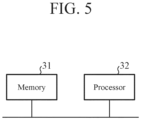
- FIG. 5 is a hardware configuration diagram of a computer in a case where the wind speed prediction device 3 is implemented by software, firmware, or the like.
- a program for causing a computer to execute each processing procedure performed in the scattering signal acquiring unit 11, the Doppler frequency calculating unit 12, the first wind speed distribution estimating unit 13, the second wind speed distribution estimating unit 14, and the wind speed prediction unit 15 is stored in a memory 31. Then, a processor 32 of the computer executes the program stored in the memory 31.
- FIG. 4 illustrates an example in which each of the components of the wind speed prediction device 3 is implemented by dedicated hardware
- FIG. 5 illustrates an example in which the wind speed prediction device 3 is implemented by software, firmware, or the like.
- this is merely an example, and some components in the wind speed prediction device 3 may be implemented by dedicated hardware, and the remaining components may be implemented by software, firmware, or the like.
- FIG. 6 is a flowchart illustrating a wind speed prediction method which is a processing procedure performed by the wind speed prediction device 3.
- the beam transmitting and receiving unit 2 when the flight area is present directly above in the vertical direction, the beam transmitting and receiving unit 2 emits beams in different directions at respective elevation angles ⁇ n by performing beam scanning at the respective elevation angles ⁇ n .
- the beam transmitting and receiving unit 2 when the position of the flight area is deviated from directly above in the vertical direction, the beam transmitting and receiving unit 2 emits beams at respective elevation angles ⁇ n while switching the elevation angles ⁇ n .
- the beam emitted from the beam transmitting and receiving unit 2 is, for example, pulsed light.
- Each beam emitted from the beam transmitting and receiving unit 2 is backscattered by fine particles such as aerosol floating in space. For example, when a plurality of fine particles is present in the line-of-sight direction of one beam, one beam is backscattered by each fine particle.
- the backscattered beam returns to the beam transmitting and receiving unit 2 as a scattering signal. Since the distances from the beam transmitting and receiving unit 2 to the plurality of fine particles are different from each other, the times at which the respective scattering signals return to the beam transmitting and receiving unit 2 are different from each other.
- the beam transmitting and receiving unit 2 outputs the angle information indicating the elevation angle ⁇ n of each beam emitted to space to the wind speed prediction device 3.
- the scattering signal acquiring unit 11 acquires each of the digital signals s ⁇ n,j (t) from the beam transmitting and receiving unit 2 (step ST1 in FIG. 6 ).
- the scattering signal acquiring unit 11 acquires the angle information indicating the elevation angle ⁇ n of each beam from the beam transmitting and receiving unit 2.
- the scattering signal acquiring unit 11 outputs each of the digital signals s ⁇ n,j (t) and the angle information to the Doppler frequency calculating unit 12.
- the Doppler frequency calculating unit 12 acquires each of the digital signals s ⁇ n,j (t) from the scattering signal acquiring unit 11, and acquires each angle information from the scattering signal acquiring unit 11. Before FFT each of the digital signals s ⁇ n,j (t) in the hit direction, the Doppler frequency calculating unit 12 sets the FFT length L ⁇ n of each of the digital signals s ⁇ n,j (t) according to the elevation angle ⁇ n indicated by the angle information (step ST2 in FIG. 6 ). The FFT length L ⁇ n corresponds to a range bin width of the scattering signal.
- the Doppler frequency calculating unit 12 sets the FFT length L ⁇ n of the digital signal s ⁇ n,j (t) in such a way that the range bin width corresponding to the FFT length L ⁇ n is proportional to 1/sin ( ⁇ n ).
- the altitudes of the plurality of observation points of the same range bin Rb m are the same altitude even if the elevation angles ⁇ n are different.
- the FFT length L ⁇ n is set shorter as the elevation angle ⁇ n is wider, and the FFT length L ⁇ n is set longer as the elevation angle ⁇ n of the scattering signal is narrower, so that a plurality of observation points in the same range bin Rb m have the same altitude.
- FIG. 7 is an explanatory diagram illustrating an observation point of the Doppler frequency.
- FIG. 7A is an explanatory diagram illustrating that the altitudes of a plurality of observation points of the same range bin Rb m are different from each other when the elevation angle ⁇ n is different.
- FIG. 7B is an explanatory diagram illustrating that a plurality of observation points in the same range bin Rb m have the same altitude even when the elevation angle ⁇ n changes.
- the FFT length L ⁇ n When the FFT length L ⁇ n is set to be short, the width of the range bin Rb m becomes narrow and the distance resolution becomes high. On the other hand, when the FFT length L ⁇ n is set to be long, the width of the range bin Rb m becomes wide and the distance resolution becomes low.
- the Doppler frequency calculating unit 12 converts each digital signal s ⁇ n,j (t) into a frequency domain signal r ⁇ n,j (f) by performing FFT with an FFT length of L ⁇ n in the hit direction for each digital signal s ⁇ n,j (t) (step ST3 in FIG. 6 ).
- the Doppler frequency calculating unit 12 calculates the respective Doppler frequencies dpf ⁇ n,j,Rbm in the plurality of range bins Rbi to Rb M from the signals r ⁇ n,j (f) in the frequency domain (step ST4 in FIG. 6 ).
- the Doppler frequency calculating unit 12 outputs the Doppler frequencies dpf ⁇ n,j,Rbm of the respective range bins Rb m to the first wind speed distribution estimating unit 13.
- the Doppler frequency calculating unit 12 may increase the calculation accuracy of the Doppler frequencies dpf ⁇ n,j,Rbm , for example, by performing the following processing.
- the Doppler frequency calculating unit 12 acquires digital signals s ⁇ n,j (t) related to a plurality of pulsed beams having the same elevation angle ⁇ n and different hit numbers, and converts the digital signals s ⁇ n,j (t) related to the plurality of beams into frequency domain signals r ⁇ n,j (f). Then, the Doppler frequency calculating unit 12 coherently integrates the signals r ⁇ n,j (f) in the plurality of frequency domains to increase the calculation accuracy of the Doppler frequencies dpf ⁇ n,j,Rbm . Since the processing itself for enhancing the calculation accuracy of the Doppler frequencies dpf ⁇ n,j,Rb . is a known technique, detailed description thereof will be omitted.
- the first wind speed distribution estimating unit 13 acquires the Doppler frequencies dpf ⁇ n,j,Rbm of the respective range bins Rb m from the Doppler frequency calculating unit 12.
- the first wind speed distribution estimating unit 13 estimates the wind speed distribution u Rbm (x, y) in the two-dimensional plane corresponding to each range bin Rb m from the plurality of Doppler frequencies dpf ⁇ 1,j,Rbm to dpf ⁇ N,j,Rbm in each range bin Rb m using the VVP method (step ST5 in FIG. 6 ).
- FIG. 8 is an explanatory diagram illustrating positions (x, y, z) of observation points of the wind speed.
- the position (x, y, z) of the observation point of the wind speed is expressed by polar coordinates centered on the position O of the beam transmitting and receiving unit 2 included in the radar device 1 as expressed by the following Expression (1).
- x y z r cos ⁇ sin ⁇ r cos ⁇ cos ⁇ r sin ⁇
- ⁇ is the elevation angle of a beam.
- ⁇ is an angle formed by a line segment connecting the center point O' of the x-y plane where the observation point is present and the position (x, y, z) of the observation point and the y axis.
- r is a distance between the position O of the beam transmitting and receiving unit 2 and the position of the observation point (x, y, z).
- the wind speed prediction device 3 can observe the wind speed in a direction parallel to the two-dimensional plane even if the wind speed prediction device 3 cannot observe the wind speed in the vertical direction with respect to the two-dimensional plane where the observation point is present.
- the general terrain corresponds to a flat terrain, an inclined terrain, a terrain having small irregularities, or the like.
- the special terrain corresponds to a terrain having a valley bottom, a terrain having a cliff with a large difference in elevation, or the like.
- the first wind speed distribution estimating unit 13 ignores the wind speed in the vertical direction, and a true wind speed vector u at the observation point is expressed as the following Expression (2).
- u u x u y
- u x represents a component in a direction parallel to the x-axis of the wind speed vector u
- u y represents a component in a direction parallel to the y-axis of the wind speed vector u.
- the first wind speed distribution estimating unit 13 performs Taylor expansion of the wind speed vector u centered on the center point O' with respect to x and y on the assumption that the wind speed u 0 at the center point O' of the x-y plane is expressed as the following Expression (3).
- Expression (3) For example, when the third and subsequent terms are ignored, the following approximate Expression (4) holds.
- u 0 u x 0 , u y 0 T u x y ⁇ u 0 + ⁇ u ⁇ x x + ⁇ u ⁇ y y + 1 2 ⁇ 2 u ⁇ x 2 x 2 + 2 ⁇ 2 u ⁇ x ⁇ y xy + ⁇ 2 u ⁇ y 2 y 2
- the first wind speed distribution estimating unit 13 acquires the observed wind speeds u r ( ⁇ 1 , ⁇ 1 ) to u r ( ⁇ K , ⁇ K ) of K beams, and substitutes the acquired observed wind speeds u r ( ⁇ 1 , ⁇ 1 ) to u r ( ⁇ K , ⁇ K ) into the following Expression (8) to estimate p illustrated in Expression (7).
- K is an integer of 2 or more.
- the K beams are K pieces of pulsed light in which sets of the elevation angle ⁇ and the angle ⁇ are different from each other.
- u r ⁇ 1 ⁇ 1 u r ⁇ 2 ⁇ 2 ⁇ u r ⁇ K ⁇ K a ⁇ 1 , ⁇ 1 T a ⁇ 2 , ⁇ 2 T ⁇ a ⁇ K , ⁇ K T p ⁇ p ⁇ a ⁇ 1 , ⁇ 1 T a ⁇ 2 , ⁇ 2 T ⁇ a ⁇ K , ⁇ K T ⁇ u r ⁇ 1 ⁇ 1 u r ⁇ 2 ⁇ 2 ⁇ u r ⁇ K ⁇ K
- a symbol " ⁇ " denotes pseudo-inverse matrix in Expression 8
- ⁇ is a symbol representing a pseudo-inverse matrix.
- the fourth, seventh, and eighth elements from the top are expressed as the sum of two parameters, and thus are uncertain elements.
- the first wind speed distribution estimating unit 13 determines the uncertain elements by equally allocating the parameter of the element of p estimated by Expression (8).
- the first wind speed distribution estimating unit 13 determines p 4 as in the following Expression (9), for example.
- the first wind speed distribution estimating unit 13 determines p 7 as in the following Expression (10), for example.
- the first wind speed distribution estimating unit 13 determines p 8 as in the following Expression (11), for example.
- the first wind speed distribution estimating unit 13 can obtain the wind speed vector u(x, y) at each observation point from the approximate Expression (4).
- the first wind speed distribution estimating unit 13 can obtain the wind speed distribution u Rbm (x, y) in the two-dimensional plane corresponding to each range bin Rb m .
- the first wind speed distribution estimating unit 13 approximates the Taylor expansion of the wind speed vector u(x, y) by 0th to 2nd order terms.
- the first wind speed distribution estimating unit 13 may approximate the Taylor expansion of the wind speed vector u(x, y) with terms of 0 degree to 3 degrees or more.
- the first wind speed distribution estimating unit 13 outputs the wind speed distribution u Rb1 (x, y) in the two-dimensional plane corresponding to the range bin Rbi to the wind speed prediction unit 15.
- the first wind speed distribution estimating unit 13 When M is 2 or more, the first wind speed distribution estimating unit 13 outputs the wind speed distribution u Rbm (x, y) in the two-dimensional plane corresponding to each range bin Rb m to the second wind speed distribution estimating unit 14.
- the second wind speed distribution estimating unit 14 acquires the wind speed distribution u Rbm (x, y) in the two-dimensional plane corresponding to each range bin Rb m from the first wind speed distribution estimating unit 13.
- the second wind speed distribution estimating unit 14 estimates a wind speed distribution u Rbm' (x, y) in a two-dimensional plane between the plurality of two-dimensional planes from the wind speed distributions u Rb1 (x, y) to u RbM (x, y) in the plurality of two-dimensional planes (step ST6 in FIG. 6 ).
- the second wind speed distribution estimating unit 14 outputs the wind speed distributions u Rb1' (x, y) to u RbM-1' (x, y) in the two-dimensional planes to the wind speed prediction unit 15.
- the second wind speed distribution estimating unit 14 calculates the distance L m-m' in the vertical direction from the two-dimensional plane in which the wind speed distribution u Rbm' (x, y) is estimated to the two-dimensional plane in which the wind speed distribution is u Rbm (x, y).
- the second wind speed distribution estimating unit 14 calculates a distance L (m+1)-m' in the vertical direction from the two-dimensional plane in which the wind speed distribution u Rbm' (x, y) is estimated to the two-dimensional plane in which the wind speed distribution is u Rbm+1 (x, y).
- the second wind speed distribution estimating unit 14 calculates a weighting coefficient w m for the wind speed distribution u Rbm (x, y) in the two-dimensional plane and a weighting coefficient w m+1 for the wind speed distribution u Rbm+1 (x, y) in the two-dimensional plane on the basis of the distance L m-m' and the distance L (m+1)-m' as expressed in the following Expressions (12) to (14).
- w m L ⁇ L m ⁇ m ′
- the second wind speed distribution estimating unit 14 estimates the wind speed distribution u Rbm' (x, y) in the two-dimensional plane between the two-dimensional plane in which the wind speed distribution is u Rbm (x, y) and the two-dimensional plane in which the wind speed distribution is u Rbm+1 (x, y) on the basis of the weighting coefficient w m and the weighting coefficient w m+1 as expressed in the following Expression (15).
- u Rbm ′ x y w m ⁇ u Rbm x y + w m + 1 ⁇ u Rbm + 1 x y w m + w m + 1
- the second wind speed distribution estimating unit 14 estimates the wind speed distribution u Rbm' (x, y) in the two-dimensional plane as a weighted average based on the distance from the two-dimensional plane in which the wind speed distribution u Rbm' (x, y) is estimated.
- this is merely an example, and for example, the second wind speed distribution estimating unit 14 compares the distance L m-m' with the distance L (m+1)-m' .
- the second wind speed distribution estimating unit 14 may use the wind speed distribution u Rbm (x, y) in the two-dimensional plane as the wind speed distribution u Rbm' (x, y) in the two-dimensional plane, and when the distance L m-m' is equal to or longer than the distance L (m+1)-m' , the second wind speed distribution estimating unit 14 may use the wind speed distribution u Rbm+1 (x, y) in the two-dimensional plane as the wind speed distribution u Rbm' (x, y) in the two-dimensional plane.
- the second wind speed distribution estimating unit 14 estimates the wind speed distribution u Rbm' (x, y) in one two-dimensional plane as the wind speed distribution in the two-dimensional plane between the two-dimensional plane in which the wind speed distribution is u Rbm (x, y) and the two-dimensional plane in which the wind speed distribution is u Rbm+1 (x, y).
- the second wind speed distribution estimating unit 14 may estimate wind speed distributions u Rbm' (x, y) of two or more two-dimensional planes having different positions in the vertical direction as the wind speed distribution in the two-dimensional plane between the two-dimensional plane in which the wind speed distribution is u Rbm (x, y) and the two-dimensional plane in which the wind speed distribution is u Rbm+1 (x, y).
- the wind speed prediction unit 15 acquires the wind speed distribution u Rb1 (x, y) in the two-dimensional plane from the first wind speed distribution estimating unit 13.
- the wind speed prediction unit 15 acquires the wind speed distributions u Rb1 (x, y) to u RbM (x, y) in the plurality of two-dimensional planes from the first wind speed distribution estimating unit 13, and acquires wind speed distributions u Rb1' (x, y) to u RbM-1' (x, y) in the two-dimensional plane from the second wind speed distribution estimating unit 14.
- the wind speed prediction unit 15 predicts the wind speed u(t) in the observation region in the two-dimensional plane from the wind speed distribution u Rb1 (x, y) in the two-dimensional plane using the two-dimensional N-S equation (step ST7 in FIG. 6 ).
- the wind speed prediction unit 15 selects the wind speed distribution in any two-dimensional plane from among the wind speed distributions u Rb1 (x, y) to u RbM (x, y) in the plurality of two-dimensional planes and the wind speed distributions u Rb1' (x, y) to u RbM-1' (x, y) in the two-dimensional planes.
- the wind speed prediction unit 15 selects the wind speed distribution u Rbm (x, y).
- the wind speed prediction unit 15 selects the wind speed distribution u Rbm' (x, y).
- the wind speed prediction unit 15 predicts the wind speed u(t) in the observation region in the selected two-dimensional plane from the wind speed distribution in the selected two-dimensional plane using the two-dimensional N-S equation (step ST7 in FIG. 6 ).
- Wind is generally considered an uncompressed fluid.
- the two-dimensional N-S equation regarding the uncompressed fluid is expressed by the following Expressions (16) and (17).
- u is a wind speed vector
- v is a viscosity coefficient
- ⁇ is a density
- p is a pressure
- f is an external force vector
- t is a time variable.
- the first term on the right side of Expression (18) is referred to as an advection term, and the second term on the right side is referred to as a pressure term.
- Expression (20) is expressed as the following Expression (23), and Expression (21) is expressed as the following Expression (24).
- Expression (23) is expressed as the following Expression (25), and Expression (24) is expressed as the following Expression (26).
- Expression (25) can be divided into two Expressions as the following Expressions (27) and (28).
- Expression (26) can be divided into two Expressions as the following Expressions (29) and (30).
- Expression (27) is transformed as Expression (31), and Expression (29) is transformed as Expression (32).
- u x ⁇ u x g ⁇ dt ⁇ u x 2 ⁇ x + ⁇ u x u y ⁇ y
- u y ⁇ u y g ⁇ dt ⁇ u x u y ⁇ x + ⁇ u y 2 ⁇ y
- Expression (28) is expressed as Expression (33) below when differentiated in the x direction
- Expression (30) is expressed as Expression (34) below when differentiated in the y direction.
- the wind speed prediction unit 15 calculates the intermediate variable u x * by substituting the discretized u x g into Expression (31), and calculates the intermediate variable u y * by substituting the discretized u y g into Expression (32).
- the wind speed prediction unit 15 calculates the pressure p from Expression (36) using the intermediate variable u x * and the intermediate variable u y *.
- the wind speed prediction unit 15 calculates a wind speed vector u x g+1 of the next time step g + 1 from Expression (28) using the intermediate variable u x * and the pressure p.
- the wind speed prediction unit 15 calculates a wind speed vector u y g+1 of the next time step g + 1 from Expression (30) using the intermediate variable u y * and the pressure p.
- the wind speed u(t) predicted by the wind speed prediction unit 15 is [u x g+1 , u y g+1 ] T , and the wind speed u(t) is displayed on, for example, a display (not illustrated).
- the calculation processing of the wind speed prediction device 3 illustrated in FIG. 3 is two-dimensional calculation processing.
- the number of two-dimensional planes is M
- the number of observation points in the observation region present in the two-dimensional plane is Cx ⁇ Cy
- the calculation amount order is approximately proportional to C 2 ⁇ M.
- the wind speed prediction device 3 can observe the wind speed in the direction parallel to the two-dimensional plane even if the wind speed prediction device 3 cannot observe the wind speed in the vertical direction with respect to the two-dimensional plane where the observation point is present.
- the wind speed in the direction parallel to the two-dimensional plane can be used as useful information for observing the wind affecting the flying object.
- the wind speed prediction device 3 includes the scattering signal acquiring unit 11 to acquire a scattering signal that is each of a plurality of beams after being emitted to space and scattered in the space, the beams having mutually different elevation angles, which are angles formed by a line-of-sight direction and a horizontal direction, the Doppler frequency calculating unit 12 to set a range bin width as distance resolution of each of scattering signals acquired by the scattering signal acquiring unit 11 according to an elevation angle of each of the beams emitted to space, and calculate a Doppler frequency of a range bin corresponding to a two-dimensional plane including an observation region from the each of the scattering signals, the first wind speed distribution estimating unit 13 to estimate a wind speed distribution in the two-dimensional plane from a plurality of Doppler frequencies calculated by the Doppler frequency calculating unit 12 using a VVP method, and the wind speed prediction unit 15 to predict a wind speed in the observation region from the wind speed distribution in the two-dimensional plane estimated by the first wind speed
- the first wind speed distribution estimating unit 13 estimates the wind speed distribution u Rbm (x, y) in the two-dimensional plane corresponding to each range bin Rb m .
- the wind speed distribution u Rbm (x, y) estimated by the first wind speed distribution estimating unit 13 may slightly deviate from the actual wind speed distribution due to the influence of observation noise.
- the first wind speed distribution estimating unit 13 may smooth the wind speed distribution u Rbm (x, y) in the time direction in order to suppress the deviation due to the influence of the observation noise.
- the smoothing of the wind speed distribution u Rbm (x, y) in the time direction can be implemented by fusing a fluid movement model such as a two-dimensional N-S equation and the estimated wind speed distribution u Rbm (x, y).
- the fusion of the fluid movement model and the wind speed distribution u Rbm (x, y) is called data assimilation.
- the first wind speed distribution estimating unit 13 performs the data assimilation processing using the data assimilation function As(-).
- the first wind speed distribution estimating unit 13 may perform the data assimilation processing by, for example, a particle filter using a two-dimensional N-S equation or an ensemble Kalman filter using the two-dimensional N-S equation.
- the first wind speed distribution estimating unit 13 may perform the data assimilation processing by an extended Kalman filter in which the two-dimensional N-S equation is approximated to a linear function or a variational method using the two-dimensional N-S equation.
- the wind speed prediction unit 15 selects the wind speed distribution in any two-dimensional plane from among the wind speed distributions u Rb1 (x, y) to u RbM (x, y) in the plurality of two-dimensional planes and the wind speed distributions u Rb1' (x, y) to u RbM-1' (x, y) in the two-dimensional planes.
- a wind speed prediction device 3 including a wind speed prediction unit 16 will be described, the wind speed prediction unit 16 estimating a wind speed distribution in a two-dimensional plane including a flight area in which a flying object is scheduled to fly as an observation region from the wind speed distributions u Rb1 (x, y) to u RbM (x, y) in the plurality of two-dimensional planes and the wind speed distributions u Rb1' (x, y) to u RbM-1' (x, y) in the two-dimensional planes.
- FIG. 9 is a configuration diagram illustrating the wind speed prediction device 3 according to the second embodiment.
- the same reference numerals as those in FIG. 3 denote the same or corresponding parts, and thus description thereof is omitted.
- FIG. 10 is a hardware configuration diagram illustrating hardware of the wind speed prediction device 3 according to the second embodiment.
- the same reference numerals as those in FIG. 4 denote the same or corresponding parts, and thus description thereof is omitted.
- the wind speed prediction device 3 illustrated in FIG. 9 includes a scattering signal acquiring unit 11, a Doppler frequency calculating unit 12, a first wind speed distribution estimating unit 13, a second wind speed distribution estimating unit 14, and the wind speed prediction unit 16.
- the wind speed prediction unit 16 is implemented by, for example, a wind speed prediction circuit 26 illustrated in FIG. 10 .
- the wind speed prediction unit 16 estimates a wind speed distribution in a two-dimensional plane including a flight area as an observation region from the wind speed distributions u Rb1 (x, y) to u RbM (x, y) in the plurality of two-dimensional planes estimated by the first wind speed distribution estimating unit 13 and the wind speed distributions u Rb1' (x, y) to u RbM-1' (x, y) in the two-dimensional plane estimated by the second wind speed distribution estimating unit 14.
- the wind speed prediction unit 16 predicts the wind speed u(t) in the flight area from the estimated wind speed distribution in the two-dimensional plane using the two-dimensional N-S equation.
- each of the scattering signal acquiring unit 11, the Doppler frequency calculating unit 12, the first wind speed distribution estimating unit 13, the second wind speed distribution estimating unit 14, and the wind speed prediction unit 16, which are components of the wind speed prediction device 3, is implemented by dedicated hardware as illustrated in FIG. 10 . That is, it is assumed that the wind speed prediction device 3 is implemented by the scattering signal acquiring circuit 21, the Doppler frequency calculating circuit 22, the first wind speed distribution estimating circuit 23, the second wind speed distribution estimating circuit 24, and the wind speed prediction circuit 26.
- Each of the scattering signal acquiring circuit 21, the Doppler frequency calculating circuit 22, the first wind speed distribution estimating circuit 23, the second wind speed distribution estimating circuit 24, and the wind speed prediction circuit 26 corresponds to, for example, a single circuit, a composite circuit, a programmed processor, a parallel-programmed processor, ASIC, FPGA, or a combination thereof.
- the components of the wind speed prediction device 3 are not limited to those implemented by dedicated hardware, and the wind speed prediction device 3 may be implemented by software, firmware, or a combination of software and firmware.
- a program for causing a computer to execute each processing procedure in the scattering signal acquiring unit 11, the Doppler frequency calculating unit 12, the first wind speed distribution estimating unit 13, the second wind speed distribution estimating unit 14, and the wind speed prediction unit 16 is stored in the memory 31 illustrated in FIG. 5 . Then, the processor 32 illustrated in FIG. 5 executes the program stored in the memory 31.
- FIG. 10 illustrates an example in which each of the components of the wind speed prediction device 3 is implemented by dedicated hardware
- FIG. 5 illustrates an example in which the wind speed prediction device 3 is implemented by software, firmware, or the like.
- this is merely an example, and some components in the wind speed prediction device 3 may be implemented by dedicated hardware, and the remaining components may be implemented by software, firmware, or the like.
- the wind speed prediction device 3 is similar to the wind speed prediction device 3 illustrated in FIG. 3 except for the wind speed prediction unit 16, and thus only the operation of the wind speed prediction unit 16 will be described here.
- the flight area is present in a two-dimensional plane between a two-dimensional plane in which the wind speed distribution is u Rbm (x, y) and a two-dimensional plane in which the wind speed distribution is u Rbm' (x, y).
- the wind speed prediction unit 16 calculates a distance L p-m in the vertical direction from the two-dimensional plane in which the flight area is present to the two-dimensional plane in which the wind speed distribution is u Rbm (x, y).
- the wind speed prediction unit 16 calculates a distance L p-m' in the vertical direction from the two-dimensional plane in which the flight area is present to the two-dimensional plane in which the wind speed distribution is u Rbm' (x, y).
- the wind speed prediction unit 16 calculates a weighting coefficient w p-m for the wind speed distribution u Rbm (x, y) in the two-dimensional plane and a weighting coefficient w p-m' for the wind speed distribution u Rbm' (x, y) in the two-dimensional plane on the basis of the distance L p-m and the distance L p-m' as expressed in the following Expressions (39) to (41).
- w p ⁇ m L ′ ⁇ L p ⁇ m L ′
- the wind speed prediction unit 16 estimates the wind speed distribution u Rbp (x, y) of the two-dimensional plane where the flight area is present on the basis of the weighting coefficient w p-m and the weighting coefficient w p-m' as expressed in the following Expression (42).
- u Rbp x y w p ⁇ m ⁇ u Rbm x y + w p ⁇ m ′ ⁇ u Rbm ′ x y w p ⁇ m + w p ⁇ m ′
- the wind speed prediction unit 16 predicts the wind speed u(t) in the flight area from the estimated wind speed distribution u Rbp (x, y) in the two-dimensional plane using the two-dimensional N-S equation.
- the prediction processing of the wind speed u(t) performed by the wind speed prediction unit 16 is similar to the prediction processing of the wind speed u(t) performed by the wind speed prediction unit 15 illustrated in FIG. 3 .
- a wind speed prediction device 3 including a time notification unit 17 that calculates a time t at which the wind speed u(t) predicted by the wind speed prediction unit 15 becomes equal to or higher than the threshold Th and gives a notification of the time t will be described.
- FIG. 11 is a configuration diagram illustrating the wind speed prediction device 3 according to the third embodiment.
- the same reference numerals as those in FIGS. 3 and 9 denote the same or corresponding parts, and thus description thereof is omitted.
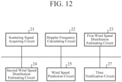
- FIG. 12 is a hardware configuration diagram illustrating hardware of the wind speed prediction device 3 according to the third embodiment.
- the same reference numerals as those in FIGS. 4 and 10 denote the same or corresponding parts, and thus description thereof is omitted.
- the wind speed prediction device 3 illustrated in FIG. 11 includes a scattering signal acquiring unit 11, a Doppler frequency calculating unit 12, a first wind speed distribution estimating unit 13, a second wind speed distribution estimating unit 14, the wind speed prediction unit 15, and the time notification unit 17.
- the time notification unit 17 is implemented by, for example, a time notification circuit 27 illustrated in FIG. 12 .
- the time notification unit 17 specifies the time t at which the wind speed u(t) predicted by the wind speed prediction unit 15 becomes equal to or higher than the threshold Th.
- the time notification unit 17 gives a notification of the specified time t to, for example, a flying object or a control tower monitoring a flight state of the flying object.
- FIG. 11 illustrates an example in which the time notification unit 17 is applied to the wind speed prediction device 3 illustrated in FIG. 3 .
- this is merely an example, and the time notification unit 17 may be applied to the wind speed prediction device 3 illustrated in FIG. 9 .
- each of the scattering signal acquiring unit 11, the Doppler frequency calculating unit 12, the first wind speed distribution estimating unit 13, the second wind speed distribution estimating unit 14, the wind speed prediction unit 15, and the time notification unit 17, which are components of the wind speed prediction device 3, is implemented by dedicated hardware as illustrated in FIG. 12 . That is, it is assumed that the wind speed prediction device 3 is implemented by the scattering signal acquiring circuit 21, the Doppler frequency calculating circuit 22, the first wind speed distribution estimating circuit 23, the second wind speed distribution estimating circuit 24, the wind speed prediction circuit 25, and the time notification circuit 27.
- Each of the scattering signal acquiring circuit 21, the Doppler frequency calculating circuit 22, the first wind speed distribution estimating circuit 23, the second wind speed distribution estimating circuit 24, the wind speed prediction circuit 25, and the time notification circuit 27 corresponds to, for example, a single circuit, a composite circuit, a programmed processor, a parallel-programmed processor, ASIC, FPGA, or a combination thereof.
- the components of the wind speed prediction device 3 are not limited to those implemented by dedicated hardware, and the wind speed prediction device 3 may be implemented by software, firmware, or a combination of software and firmware.
- the wind speed prediction device 3 is implemented by software, firmware, or the like
- a program for causing a computer to execute each processing procedure in the scattering signal acquiring unit 11, the Doppler frequency calculating unit 12, the first wind speed distribution estimating unit 13, the second wind speed distribution estimating unit 14, the wind speed prediction unit 15, and the time notification unit 17 is stored in the memory 31 illustrated in FIG. 5 .
- the processor 32 illustrated in FIG. 5 executes the program stored in the memory 31.
- FIG. 12 illustrates an example in which each of the components of the wind speed prediction device 3 is implemented by dedicated hardware
- FIG. 5 illustrates an example in which the wind speed prediction device 3 is implemented by software, firmware, or the like.
- this is merely an example, and some components in the wind speed prediction device 3 may be implemented by dedicated hardware, and the remaining components may be implemented by software, firmware, or the like.
- the wind speed prediction device 3 is similar to the wind speed prediction device 3 illustrated in FIG. 3 except for the time notification unit 17, and thus only the operation of the time notification unit 17 will be described here.
- the time notification unit 17 acquires the predicted wind speed u(t) from the wind speed prediction unit 15 every time the wind speed prediction unit 15 predicts the wind speed u(t).
- the time notification unit 17 compares the wind speed u(t) with the threshold Th.
- the threshold Th is, for example, a lower limit value of the wind speed that may affect the flight of the flying object.
- the threshold Th may be stored in the internal memory of the time notification unit 17 or may be given from the outside.
- the time notification unit 17 specifies the time t at which the wind speed u(t) is equal to or higher than the threshold Th on the basis of the comparison result between the wind speed u(t) and the threshold Th.
- the time notification unit 17 gives a notification of the specified time t to, for example, a flying object or a control tower monitoring a flight state of the flying object.
- the wind speed prediction device 3 illustrated in FIG. 11 includes the time notification unit 17 that specifies the time at which the wind speed predicted by the wind speed prediction unit 15 becomes equal to or higher than the threshold and gives a notification of the specified time t. Therefore, the wind speed prediction device 3 illustrated in FIG. 11 can predict the wind speed without performing three-dimensional calculation processing, as does the wind speed prediction device 3 illustrated in FIG. 3 . In addition, it is possible to notify the time when wind that may affect the flight of the flying object blows.
- the present disclosure is suitable for a wind speed prediction device, a wind speed prediction method, and a radar device.
- 1 radar device, 2: beam transmitting and receiving unit, 3: wind speed prediction device, 11: scattering signal acquiring unit, 12: Doppler frequency calculating unit, 13: first wind speed distribution estimating unit, 14: second wind speed distribution estimating unit, 15, 16: wind speed prediction unit, 17: time notification unit, 21: scattering signal acquiring circuit, 22: doppler frequency calculating circuit, 23: first wind speed distribution estimating circuit, 24: second wind speed distribution estimating circuit, 25, 26: wind speed prediction circuit, 27: time notification circuit, 31: memory, 32: processor
Landscapes
- Engineering & Computer Science (AREA)
- Physics & Mathematics (AREA)
- Remote Sensing (AREA)
- Radar, Positioning & Navigation (AREA)
- Electromagnetism (AREA)
- General Physics & Mathematics (AREA)
- Computer Networks & Wireless Communication (AREA)
- Environmental & Geological Engineering (AREA)
- Atmospheric Sciences (AREA)
- Environmental Sciences (AREA)
- Ecology (AREA)
- Biodiversity & Conservation Biology (AREA)
- Life Sciences & Earth Sciences (AREA)
- Radar Systems Or Details Thereof (AREA)
- Optical Radar Systems And Details Thereof (AREA)
Abstract
Description
- The present disclosure relates to a wind speed prediction device, a wind speed prediction method, and a radar device.
- Some wind speed prediction devices that predict a wind speed in an observation region include a wind speed prediction device (hereinafter referred to as a "conventional wind speed prediction device") that predicts a wind speed in an observation region by simulating the wind speed using a weather model (see Patent Literature 1). The simulation of the wind speed is three-dimensional calculation processing.
- Patent Literature 1:
Japanese Patent Application Laid-Open No. 2014-202190 - The conventional wind speed prediction device disclosed in
Patent Literature 1 performs three-dimensional calculation processing, and thus has a problem that a calculation load may increase. - The present disclosure has been made to solve the above problems, and an object thereof is to obtain a wind speed prediction device and a wind speed prediction method capable of predicting a wind speed without performing three-dimensional calculation processing.
- A wind speed prediction device according to the present disclosure includes a scattering signal acquiring unit to acquire a scattering signal that is each of a plurality of beams after being emitted to space and scattered in the space, the beams having mutually different elevation angles, which are angles formed by a line-of-sight direction and a horizontal direction, a Doppler frequency calculating unit to set a range bin width as distance resolution of each of scattering signals acquired by the scattering signal acquiring unit in accordance with an elevation angle of each of the beams emitted to the space, and calculate a Doppler frequency of a range bin corresponding to a two-dimensional plane including an observation region from the each of the scattering signals, a first wind speed distribution estimating unit to estimate a wind speed distribution in the two-dimensional plane from a plurality of Doppler frequencies calculated by the Doppler frequency calculating unit using a volume velocity processing (VVP) method, and a wind speed prediction unit to predict a wind speed in the observation region from the wind speed distribution in the two-dimensional plane estimated by the first wind speed distribution estimating unit using a two-dimensional Navier-Stokes equation.
- According to the present disclosure, a wind speed can be predicted without performing three-dimensional calculation processing.
-
-
FIG. 1 is a configuration diagram illustrating aradar device 1 including a windspeed prediction device 3 according to a first embodiment. -
FIG. 2A is an explanatory diagram illustrating a plurality of beams in a case where the position of a flight area is directly above a beam transmitting and receivingunit 2 in a vertical direction, andFIG. 2B is an explanatory diagram illustrating a plurality of beams in a case where the position of the flight area is deviated from directly above the beam transmitting and receivingunit 2 in the vertical direction. -
FIG. 3 is a configuration diagram illustrating a windspeed prediction device 3 according to the first embodiment. -
FIG. 4 is a hardware configuration diagram illustrating hardware of the windspeed prediction device 3 according to the first embodiment. -
FIG. 5 is a hardware configuration diagram of a computer in a case where the windspeed prediction device 3 is implemented by software, firmware, or the like. -
FIG. 6 is a flowchart illustrating a wind speed prediction method which is a processing procedure performed by the windspeed prediction device 3. -
FIG. 7A is an explanatory diagram illustrating that altitudes of a plurality of observation points of the same range bin Rbm are different from each other when an elevation angle θn is different, andFIG. 7B is an explanatory diagram illustrating that a plurality of observation points of the same range bin Rbm are at the same altitude even when the elevation angle θn is changed. -
FIG. 8 is an explanatory diagram illustrating positions (x, y, z) of observation points of the wind speed. -
FIG. 9 is a configuration diagram illustrating a windspeed prediction device 3 according to a second embodiment. -
FIG. 10 is a hardware configuration diagram illustrating hardware of the windspeed prediction device 3 according to the second embodiment. -
FIG. 11 is a configuration diagram illustrating a windspeed prediction device 3 according to a third embodiment. -
FIG. 12 is a hardware configuration diagram illustrating hardware of the windspeed prediction device 3 according to the third embodiment. - Hereinafter, in order to describe the present disclosure in more detail, modes for carrying out the present disclosure will be described with reference to the accompanying drawings.
-
FIG. 1 is a configuration diagram illustrating aradar device 1 including a windspeed prediction device 3 according to a first embodiment. - The
radar device 1 illustrated inFIG. 1 includes a beam transmitting and receivingunit 2 and a windspeed prediction device 3. -
FIG. 2 is an explanatory diagram illustrating a plurality of beams emitted to space from the beam transmitting and receivingunit 2. In the example ofFIG. 2 , the observation region is present in the space. The observation region is, for example, a flight area in which a flying object is scheduled to fly. The flying object is, for example, a drone or a helicopter. -
FIG. 2A is an explanatory diagram illustrating a plurality of beams in a case where the position of the flight area is directly above the beam transmitting and receivingunit 2 in the vertical direction. -
FIG. 2B is an explanatory diagram illustrating a plurality of beams in a case where the position of the flight area is deviated from directly above the beam transmitting and receivingunit 2 in the vertical direction. - The beam transmitting and receiving
unit 2 includes, for example, a beam generating unit, a beam transmitter, a radiation direction switching unit, an antenna, and a beam receiver. InFIG. 1 , notations of the beam generating unit, the beam transmitter, the radiation direction switching unit, the antenna, and the beam receiver are omitted. - As illustrated in
FIG. 2 , the beam transmitting and receivingunit 2 emits each of a plurality of beams having mutually different elevation angles θn (n = 1, ..., N), which are angles formed by the line-of-sight direction and the horizontal direction, into space. N is an integer of 2 or more. - That is, as illustrated in
FIG. 2A , when the flight area is present directly above in the vertical direction, the beam transmitting and receivingunit 2 emits beams in different directions at respective elevation angles θn by performing beam scanning at the respective elevation angles θn. - In
FIG. 2A , N = 3, and each of the beam with the elevation angle θ1, the beam with the elevation angle θ2, and the beam with the elevation angle θ3 is emitted from the beam transmitting and receivingunit 2 to space. InFIG. 2A , beams are emitted in four directions at the respective elevation angles θn. InFIG. 2A , black circles indicate observation points of the wind speed. - Further, as illustrated in
FIG. 2B , when the position of the flight area is deviated from directly above in the vertical direction, the beam transmitting and receivingunit 2 emits beams at respective elevation angles θn while switching the elevation angles θn. - In
FIG. 2B , N = 12, and beams of elevation angles θ1 to θ12 are emitted from the beam transmitting and receivingunit 2 to space. For simplification of the drawing, only the elevation angles θ1 to θ6 are illustrated inFIG. 2B , and the illustration of the elevation angles θ7 to θ12 is omitted. InFIG. 2B , a beam is emitted in one direction at each elevation angle θn. InFIG. 2B , black circles indicate observation points of the wind speed. - Each of
FIGS. 2A and 2B illustrates an example of obtaining wind speed distributions in three two-dimensional planes. However, this is merely an example, and wind speed distributions in one or two two-dimensional planes may be obtained, or wind speed distributions in four or more two-dimensional planes may be obtained. - As the beam emitted from the beam transmitting and receiving
unit 2, for example, in addition to continuous wave (CW) pulsed light, frequency-modulated pulsed light can be used. - The beam transmitting and receiving
unit 2 receives each beam scattered in space as a scattering signal. - The beam transmitting and receiving
unit 2 converts each scattering signal from an analog signal to a digital signal, and outputs the digital signal to the windspeed prediction device 3. - Further, the beam transmitting and receiving
unit 2 outputs angle information indicating the elevation angle θn of each beam emitted to space to the windspeed prediction device 3. - In the
radar device 1 illustrated inFIG. 1 , it is assumed that the beam transmitting and receivingunit 2 includes a beam generating unit, a beam transmitter, a radiation direction switching unit, an antenna, and a beam receiver. However, the beam transmitting and receivingunit 2 is only required to emit each of a plurality of beams having different elevation angles θn into space and receive each beam scattered in the space as a scattering signal, and may have any configuration. -
FIG. 3 is a configuration diagram illustrating the windspeed prediction device 3 according to the first embodiment. -
FIG. 4 is a hardware configuration diagram illustrating hardware of the windspeed prediction device 3 according to the first embodiment. - The wind
speed prediction device 3 illustrated inFIG. 3 includes a scatteringsignal acquiring unit 11, a Dopplerfrequency calculating unit 12, a first wind speeddistribution estimating unit 13, a second wind speeddistribution estimating unit 14, and a windspeed prediction unit 15. - The scattering
signal acquiring unit 11 is implemented by, for example, a scatteringsignal acquiring circuit 21 illustrated inFIG. 4 . - The scattering
signal acquiring unit 11 acquires each of digital signals sθn,j(t) from the beam transmitting and receivingunit 2 as each of scattering signals after being scattered in space. j = 1, ..., J. j is the scan number of beam scanning at the elevation angle θn. In the example ofFIG. 2A , since beams are emitted in four directions at each elevation angle θn, J = 4. In the example ofFIG. 2B , since the beam is emitted in one direction at each elevation angle θn, J = 1. t is a variable indicating time. - Further, the scattering
signal acquiring unit 11 acquires the angle information indicating the elevation angle θn of each beam emitted into space by the beam transmitting and receivingunit 2. - The scattering
signal acquiring unit 11 outputs each of the digital signals sθn,j(t) and the angle information to the Dopplerfrequency calculating unit 12. - The Doppler
frequency calculating unit 12 is implemented by, for example, a Dopplerfrequency calculating circuit 22 illustrated inFIG. 4 . - The Doppler
frequency calculating unit 12 acquires each of the digital signals sθn,j(t) and the angle information from the scatteringsignal acquiring unit 11. - Before performing fast Fourier transformation (FFT) on each digital signal sθn,j(t) in the hit direction, the Doppler
frequency calculating unit 12 sets a range bin width as the distance resolution of each digital signal sθn,j(t) according to the elevation angle θn indicated by the angle information. That is, the Dopplerfrequency calculating unit 12 sets an FFT length Lθn corresponding to the range bin width. - The FFT length Lθn is set shorter as the elevation angle θn of the beam emitted to space is wider, and is set longer as the elevation angle θn of the beam emitted to the space is narrower.
- In the example of
FIG. 2A , the FFT length Lθ1 of the digital signal sθ1,j(t) corresponding to the beam at the elevation angle θ1 is longer than the FFT length Lθ2 of the digital signal sθ2,j(t) corresponding to the beam at the elevation angle θ2, and the FFT length Lθ2 of the digital signal sθ2,j(t) corresponding to the beam at the elevation angle θ2 is longer than the FFT length Lθ3 of the digital signal sθ3,j(t) corresponding to the beam at the elevation angle θ3. - The Doppler
frequency calculating unit 12 converts each of the digital signals sθn,j(t) into frequency domain signals rθn,j(f) by performing FFT on the digital signals sθn,j(t) acquired by the scatteringsignal acquiring unit 11 in the hit direction. f is a variable indicating a frequency. - The Doppler
frequency calculating unit 12 calculates the respective Doppler frequencies dpfθn,j,Rbm in a plurality of range bins Rbi to RbM from the signals rθn,j(f) in the frequency domain. m = 1, ..., M, and M is an integer of 1 or more. -
FIG. 2 illustrates an example of obtaining wind speed distributions in three two-dimensional planes. As illustrated inFIG. 2 , in a case of obtaining wind speed distributions in three two-dimensional planes, the Dopplerfrequency calculating unit 12 calculates the Doppler frequencies dpfθn,j,Rbm in the range bins Rb1, Rb2, and Rb3 from the signals rθn,j(f) in the frequency domain. - In the wind
speed prediction device 3 illustrated inFIG. 3 , it is assumed that M is an integer of 2 or more. Here, M is not limited to an integer of 2 or more, and M = 1 may be set. - When M = 1, the Doppler
frequency calculating unit 12 calculates only the Doppler frequency dpfθn,j,Rb1 of one range bin Rbi including the observation region from the frequency domain signal rθn,j(f). - The Doppler
frequency calculating unit 12 outputs the Doppler frequencies dpfθn,j,Rbm of the respective range bins Rbm to the first wind speeddistribution estimating unit 13. - The first wind speed
distribution estimating unit 13 is implemented by, for example, a first wind speeddistribution estimating circuit 23 illustrated inFIG. 4 . - The first wind speed
distribution estimating unit 13 estimates a wind speed distribution uRbm(x, y) in a two-dimensional plane corresponding to each range bin Rbm using a volume velocity processing (VVP) method from a plurality of Doppler frequencies dpfθ1,j,Rbm to dpfθN,j,Rbm in each range bin Rbm calculated by the Dopplerfrequency calculating unit 12. - When M is 1, the first wind speed
distribution estimating unit 13 estimates the wind speed distribution uRb1(x, y) in the two-dimensional plane corresponding to the range bin Rbi as the two-dimensional plane including the observation region, and outputs the wind speed distribution uRb1(x, y) in the two-dimensional plane to the windspeed prediction unit 15. - When M is 2 or more, the first wind speed
distribution estimating unit 13 outputs the wind speed distribution uRbm(x, y) in the two-dimensional plane corresponding to each range bin Rbm to the second wind speeddistribution estimating unit 14. - The second wind speed
distribution estimating unit 14 is implemented by, for example, a second wind speeddistribution estimating circuit 24 illustrated inFIG. 4 . - The second wind speed
distribution estimating unit 14 estimates a wind speed distribution uRbm'(x, y) in a two-dimensional plane between a plurality of two-dimensional planes from the wind speed distributions uRb1(x, y) to uRbM(x, y) in the plurality of two-dimensional planes estimated by the first wind speeddistribution estimating unit 13. For example, the wind speed distribution uRb1'(x, y) in the two-dimensional plane is a wind speed distribution in the two-dimensional plane between the two-dimensional plane corresponding to the range bin Rbi and the two-dimensional plane corresponding to the range bin Rb2. The wind speed distribution uRb2'(x, y) in the two-dimensional plane is a wind speed distribution in the two-dimensional plane between the two-dimensional plane corresponding to the range bin Rb2 and the two-dimensional plane corresponding to the range bin Rb3. - The second wind speed
distribution estimating unit 14 outputs the wind speed distributions uRb1'(x, y) to uRbM-1'(x, y) in the two-dimensional plane between the plurality of two-dimensional planes to the windspeed prediction unit 15. - The wind
speed prediction unit 15 is implemented by, for example, a windspeed prediction circuit 25 illustrated inFIG. 4 . - When M is 1, the wind
speed prediction unit 15 predicts a wind speed u(t) in the observation region from the wind speed distribution uRb1(x, y) in the two-dimensional plane estimated by the first wind speeddistribution estimating unit 13 using the two-dimensional Navier-Stokes equation (hereinafter referred to as a "two-dimensional N-S equation"). The observation region is, for example, an area including a flight area in which the flying object is scheduled to fly. - When M is 2 or more, the wind
speed prediction unit 15 selects the wind speed distribution in the two-dimensional plane including the flight area as the observation region from the wind speed distributions uRb1(x, y) to uRbM(x, y) in the plurality of two-dimensional planes estimated by the first wind speeddistribution estimating unit 13 and the wind speed distributions uRb1'(x, y) to uRbM-1'(x, y) in the two-dimensional plane estimated by the second wind speeddistribution estimating unit 14. - The wind
speed prediction unit 15 predicts the wind speed u(t) in the flight area from the wind speed distribution in the selected two-dimensional plane using the two-dimensional N-S equation. - In
FIG. 3 , it is assumed that each of the scatteringsignal acquiring unit 11, the Dopplerfrequency calculating unit 12, the first wind speeddistribution estimating unit 13, the second wind speeddistribution estimating unit 14, and the windspeed prediction unit 15, which are components of the windspeed prediction device 3, is implemented by dedicated hardware as illustrated inFIG. 4 . That is, it is assumed that the windspeed prediction device 3 is implemented by the scatteringsignal acquiring circuit 21, the Dopplerfrequency calculating circuit 22, the first wind speeddistribution estimating circuit 23, the second wind speeddistribution estimating circuit 24, and the windspeed prediction circuit 25. - Each of the scattering
signal acquiring circuit 21, the Dopplerfrequency calculating circuit 22, the first wind speeddistribution estimating circuit 23, the second wind speeddistribution estimating circuit 24, and the windspeed prediction circuit 25 corresponds to, for example, a single circuit, a composite circuit, a programmed processor, a parallel-programmed processor, an application specific integrated circuit (ASIC), a field-programmable gate array (FPGA), or a combination thereof. - The components of the wind
speed prediction device 3 are not limited to those implemented by dedicated hardware, and the windspeed prediction device 3 may be implemented by software, firmware, or a combination of software and firmware. - Software or firmware is stored in a memory of the computer as a program. The computer means hardware that executes a program, and corresponds to, for example, a central processing unit (CPU), a central processing device, a processing device, an arithmetic device, a microprocessor, a microcomputer, a processor, or a digital signal processor (DSP).
-
FIG. 5 is a hardware configuration diagram of a computer in a case where the windspeed prediction device 3 is implemented by software, firmware, or the like. - In a case where the wind
speed prediction device 3 is implemented by software, firmware, or the like, a program for causing a computer to execute each processing procedure performed in the scatteringsignal acquiring unit 11, the Dopplerfrequency calculating unit 12, the first wind speeddistribution estimating unit 13, the second wind speeddistribution estimating unit 14, and the windspeed prediction unit 15 is stored in amemory 31. Then, aprocessor 32 of the computer executes the program stored in thememory 31. - Further,
FIG. 4 illustrates an example in which each of the components of the windspeed prediction device 3 is implemented by dedicated hardware, andFIG. 5 illustrates an example in which the windspeed prediction device 3 is implemented by software, firmware, or the like. However, this is merely an example, and some components in the windspeed prediction device 3 may be implemented by dedicated hardware, and the remaining components may be implemented by software, firmware, or the like. - Next, the operation of the
radar device 1 illustrated inFIG. 1 will be described. -
FIG. 6 is a flowchart illustrating a wind speed prediction method which is a processing procedure performed by the windspeed prediction device 3. - As illustrated in
FIG. 2 , the beam transmitting and receivingunit 2 emits each of a plurality of beams having different elevation angles θn (n = 1, ..., N) to space. - That is, as illustrated in
FIG. 2A , when the flight area is present directly above in the vertical direction, the beam transmitting and receivingunit 2 emits beams in different directions at respective elevation angles θn by performing beam scanning at the respective elevation angles θn. - As illustrated in
FIG. 2B , when the position of the flight area is deviated from directly above in the vertical direction, the beam transmitting and receivingunit 2 emits beams at respective elevation angles θn while switching the elevation angles θn. The beam emitted from the beam transmitting and receivingunit 2 is, for example, pulsed light. - Each beam emitted from the beam transmitting and receiving
unit 2 is backscattered by fine particles such as aerosol floating in space. For example, when a plurality of fine particles is present in the line-of-sight direction of one beam, one beam is backscattered by each fine particle. The backscattered beam returns to the beam transmitting and receivingunit 2 as a scattering signal. Since the distances from the beam transmitting and receivingunit 2 to the plurality of fine particles are different from each other, the times at which the respective scattering signals return to the beam transmitting and receivingunit 2 are different from each other. - The beam transmitting and receiving
unit 2 converts each scattering signal from an analog signal into a digital signal sθn,j(t) (n = 1, ..., N: j = 1, ..., J), and outputs the digital signal sθn,j to the windspeed prediction device 3. - Further, the beam transmitting and receiving
unit 2 outputs the angle information indicating the elevation angle θn of each beam emitted to space to the windspeed prediction device 3. - The scattering
signal acquiring unit 11 acquires each of the digital signals sθn,j(t) from the beam transmitting and receiving unit 2 (step ST1 inFIG. 6 ). - Further, the scattering
signal acquiring unit 11 acquires the angle information indicating the elevation angle θn of each beam from the beam transmitting and receivingunit 2. - The scattering
signal acquiring unit 11 outputs each of the digital signals sθn,j(t) and the angle information to the Dopplerfrequency calculating unit 12. - The Doppler
frequency calculating unit 12 acquires each of the digital signals sθn,j(t) from the scatteringsignal acquiring unit 11, and acquires each angle information from the scatteringsignal acquiring unit 11. Before FFT each of the digital signals sθn,j(t) in the hit direction, the Dopplerfrequency calculating unit 12 sets the FFT length Lθn of each of the digital signals sθn,j(t) according to the elevation angle θn indicated by the angle information (step ST2 inFIG. 6 ). The FFT length Lθn corresponds to a range bin width of the scattering signal. - That is, the Doppler
frequency calculating unit 12 sets the FFT length Lθn of the digital signal sθn,j(t) in such a way that the range bin width corresponding to the FFT length Lθn is proportional to 1/sin (θn). - In a case where the FFT lengths Lθn of the respective digital signals sθn,j(t) are the same, when the elevation angles θn are different, as illustrated in
FIG. 7A , the altitudes of a plurality of observation points of the same range bin Rbm are different from each other. - On the other hand, in a case where the FFT lengths Lθn of the respective digital signals sθn,j(t) are set according to the elevation angle θn, as illustrated in
FIG. 7B , the altitudes of the plurality of observation points of the same range bin Rbm are the same altitude even if the elevation angles θn are different. - In the
radar device 1 illustrated inFIG. 1 , the FFT length Lθn is set shorter as the elevation angle θn is wider, and the FFT length Lθn is set longer as the elevation angle θn of the scattering signal is narrower, so that a plurality of observation points in the same range bin Rbm have the same altitude. -
FIG. 7 is an explanatory diagram illustrating an observation point of the Doppler frequency. -
FIG. 7A is an explanatory diagram illustrating that the altitudes of a plurality of observation points of the same range bin Rbm are different from each other when the elevation angle θn is different. -
FIG. 7B is an explanatory diagram illustrating that a plurality of observation points in the same range bin Rbm have the same altitude even when the elevation angle θn changes. - When the FFT length Lθn is set to be short, the width of the range bin Rbm becomes narrow and the distance resolution becomes high. On the other hand, when the FFT length Lθn is set to be long, the width of the range bin Rbm becomes wide and the distance resolution becomes low.
- The Doppler
frequency calculating unit 12 converts each digital signal sθn,j(t) into a frequency domain signal rθn,j(f) by performing FFT with an FFT length of Lθn in the hit direction for each digital signal sθn,j(t) (step ST3 inFIG. 6 ). - The Doppler
frequency calculating unit 12 calculates the respective Doppler frequencies dpfθn,j,Rbm in the plurality of range bins Rbi to RbM from the signals rθn,j(f) in the frequency domain (step ST4 inFIG. 6 ). - The Doppler
frequency calculating unit 12 outputs the Doppler frequencies dpfθn,j,Rbm of the respective range bins Rbm to the first wind speeddistribution estimating unit 13. - Since the processing itself of calculating the Doppler frequencies dpfθn,j,Rbm of the range bin Rbm is a known technique, detailed description thereof will be omitted.
- Note that calculation accuracy of the Doppler frequencies dpfθn,j,Rbm may be lowered due to a low signal to noise ratio (SNR) of the digital signal sθn,j(t). In such a case, the Doppler
frequency calculating unit 12 may increase the calculation accuracy of the Doppler frequencies dpfθn,j,Rbm, for example, by performing the following processing. - For example, the Doppler
frequency calculating unit 12 acquires digital signals sθn,j(t) related to a plurality of pulsed beams having the same elevation angle θn and different hit numbers, and converts the digital signals sθn,j(t) related to the plurality of beams into frequency domain signals rθn,j(f). Then, the Dopplerfrequency calculating unit 12 coherently integrates the signals rθn,j(f) in the plurality of frequency domains to increase the calculation accuracy of the Doppler frequencies dpfθn,j,Rbm. Since the processing itself for enhancing the calculation accuracy of the Doppler frequencies dpfθn,j,Rb. is a known technique, detailed description thereof will be omitted. - The first wind speed
distribution estimating unit 13 acquires the Doppler frequencies dpfθn,j,Rbm of the respective range bins Rbm from the Dopplerfrequency calculating unit 12. - The first wind speed
distribution estimating unit 13 estimates the wind speed distribution uRbm(x, y) in the two-dimensional plane corresponding to each range bin Rbm from the plurality of Doppler frequencies dpfθ1,j,Rbm to dpfθN,j,Rbm in each range bin Rbm using the VVP method (step ST5 inFIG. 6 ). - Hereinafter, estimation processing of the wind speed distribution uRbm(x, y) in the two-dimensional plane by the first wind speed
distribution estimating unit 13 will be specifically described. -
FIG. 8 is an explanatory diagram illustrating positions (x, y, z) of observation points of the wind speed. - The position (x, y, z) of the observation point of the wind speed is expressed by polar coordinates centered on the position O of the beam transmitting and receiving
unit 2 included in theradar device 1 as expressed by the following Expression (1).
- In Expression (1), θ is the elevation angle of a beam. ϕ is an angle formed by a line segment connecting the center point O' of the x-y plane where the observation point is present and the position (x, y, z) of the observation point and the y axis. r is a distance between the position O of the beam transmitting and receiving
unit 2 and the position of the observation point (x, y, z). - For example, when the terrain of the ground surface vertically below the observation point is not a special terrain but a general terrain, there is no practical problem in observing the wind affecting the flying object as long as the wind
speed prediction device 3 can observe the wind speed in a direction parallel to the two-dimensional plane even if the windspeed prediction device 3 cannot observe the wind speed in the vertical direction with respect to the two-dimensional plane where the observation point is present. - The general terrain corresponds to a flat terrain, an inclined terrain, a terrain having small irregularities, or the like. The special terrain corresponds to a terrain having a valley bottom, a terrain having a cliff with a large difference in elevation, or the like.
- Accordingly, in the wind
speed prediction device 3 illustrated inFIG. 3 , the first wind speeddistribution estimating unit 13 ignores the wind speed in the vertical direction, and a true wind speed vector u at the observation point is expressed as the following Expression (2).
- In Expression (2), ux represents a component in a direction parallel to the x-axis of the wind speed vector u, and uy represents a component in a direction parallel to the y-axis of the wind speed vector u.
- The first wind speed
distribution estimating unit 13 performs Taylor expansion of the wind speed vector u centered on the center point O' with respect to x and y on the assumption that the wind speed u0 at the center point O' of the x-y plane is expressed as the following Expression (3). For example, when the third and subsequent terms are ignored, the following approximate Expression (4) holds.

- Since what is observed by the
radar device 1 is the speed in the line-of-sight direction of the wind speed at the observation point, an observed wind speed ur(θ, ϕ) is expressed as the following Expression (5).


- The first wind speed
distribution estimating unit 13 acquires the observed wind speeds ur(θ1, ϕ1) to ur(θK, ϕK) of K beams, and substitutes the acquired observed wind speeds ur(θ1, ϕ1) to ur(θK, ϕK) into the following Expression (8) to estimate p illustrated in Expression (7). K is an integer of 2 or more. The K beams are K pieces of pulsed light in which sets of the elevation angle θ and the angle ϕ are different from each other.
- A symbol "†" denotes pseudo-inverse matrix in
Expression 8
In Expression (8), † is a symbol representing a pseudo-inverse matrix. - Among the elements of p illustrated in Expression (7), the fourth, seventh, and eighth elements from the top are expressed as the sum of two parameters, and thus are uncertain elements.
- The first wind speed
distribution estimating unit 13 determines the uncertain elements by equally allocating the parameter of the element of p estimated by Expression (8). - When the fourth element from the top among the elements of p is p4, the first wind speed
distribution estimating unit 13 determines p4 as in the following Expression (9), for example. - When the seventh element from the top among the elements of p is p7, the first wind speed
distribution estimating unit 13 determines p7 as in the following Expression (10), for example. - When the eighth element from the top among the elements of p is p8, the first wind speed
distribution estimating unit 13 determines p8 as in the following Expression (11), for example.


- As described above, since all the coefficients u0, ∂u/∂x, ∂u/∂y, ∂2u/∂x2, ∂2u/∂x∂y, and ∂2u/∂y2 illustrated in the approximate Expression (4) are determined, the first wind speed
distribution estimating unit 13 can obtain the wind speed vector u(x, y) at each observation point from the approximate Expression (4). - When the wind speed vector u(x, y) at each observation point can be obtained, the first wind speed
distribution estimating unit 13 can obtain the wind speed distribution uRbm(x, y) in the two-dimensional plane corresponding to each range bin Rbm. - Here, the first wind speed
distribution estimating unit 13 approximates the Taylor expansion of the wind speed vector u(x, y) by 0th to 2nd order terms. However, this is merely an example, and the first wind speeddistribution estimating unit 13 may approximate the Taylor expansion of the wind speed vector u(x, y) with terms of 0 degree to 3 degrees or more. - When M is 1, the first wind speed
distribution estimating unit 13 outputs the wind speed distribution uRb1(x, y) in the two-dimensional plane corresponding to the range bin Rbi to the windspeed prediction unit 15. - When M is 2 or more, the first wind speed
distribution estimating unit 13 outputs the wind speed distribution uRbm(x, y) in the two-dimensional plane corresponding to each range bin Rbm to the second wind speeddistribution estimating unit 14. - The second wind speed
distribution estimating unit 14 acquires the wind speed distribution uRbm(x, y) in the two-dimensional plane corresponding to each range bin Rbm from the first wind speeddistribution estimating unit 13. - The second wind speed
distribution estimating unit 14 estimates a wind speed distribution uRbm'(x, y) in a two-dimensional plane between the plurality of two-dimensional planes from the wind speed distributions uRb1(x, y) to uRbM(x, y) in the plurality of two-dimensional planes (step ST6 inFIG. 6 ). - The second wind speed
distribution estimating unit 14 outputs the wind speed distributions uRb1'(x, y) to uRbM-1'(x, y) in the two-dimensional planes to the windspeed prediction unit 15. - Hereinafter, estimation processing of the wind speed distribution uRbm'(x, y) in the two-dimensional plane by the second wind speed
distribution estimating unit 14 will be specifically described. - For example, when estimating the wind speed distribution uRbm'(x, y) in the two-dimensional plane between the two-dimensional plane in which the wind speed distribution is uRbm(x, y) and a two-dimensional plane in which the wind speed distribution is uRbm+1(x, y), the second wind speed
distribution estimating unit 14 calculates the distance Lm-m' in the vertical direction from the two-dimensional plane in which the wind speed distribution uRbm'(x, y) is estimated to the two-dimensional plane in which the wind speed distribution is uRbm(x, y). - Further, the second wind speed
distribution estimating unit 14 calculates a distance L(m+1)-m' in the vertical direction from the two-dimensional plane in which the wind speed distribution uRbm'(x, y) is estimated to the two-dimensional plane in which the wind speed distribution is uRbm+1(x, y). - The second wind speed
distribution estimating unit 14 calculates a weighting coefficient wm for the wind speed distribution uRbm(x, y) in the two-dimensional plane and a weighting coefficient wm+1 for the wind speed distribution uRbm+1(x, y) in the two-dimensional plane on the basis of the distance Lm-m' and the distance L(m+1)-m' as expressed in the following Expressions (12) to (14).


- The second wind speed
distribution estimating unit 14 estimates the wind speed distribution uRbm'(x, y) in the two-dimensional plane between the two-dimensional plane in which the wind speed distribution is uRbm(x, y) and the two-dimensional plane in which the wind speed distribution is uRbm+1(x, y) on the basis of the weighting coefficient wm and the weighting coefficient wm+1 as expressed in the following Expression (15).
- Here, the second wind speed
distribution estimating unit 14 estimates the wind speed distribution uRbm'(x, y) in the two-dimensional plane as a weighted average based on the distance from the two-dimensional plane in which the wind speed distribution uRbm'(x, y) is estimated. However, this is merely an example, and for example, the second wind speeddistribution estimating unit 14 compares the distance Lm-m' with the distance L(m+1)-m'. When the distance Lm-m' is shorter than the distance L(m+1)-m', the second wind speeddistribution estimating unit 14 may use the wind speed distribution uRbm(x, y) in the two-dimensional plane as the wind speed distribution uRbm'(x, y) in the two-dimensional plane, and when the distance Lm-m' is equal to or longer than the distance L(m+1)-m', the second wind speeddistribution estimating unit 14 may use the wind speed distribution uRbm+1(x, y) in the two-dimensional plane as the wind speed distribution uRbm'(x, y) in the two-dimensional plane. - Further, here, the second wind speed
distribution estimating unit 14 estimates the wind speed distribution uRbm'(x, y) in one two-dimensional plane as the wind speed distribution in the two-dimensional plane between the two-dimensional plane in which the wind speed distribution is uRbm(x, y) and the two-dimensional plane in which the wind speed distribution is uRbm+1(x, y). However, this is merely an example, and the second wind speeddistribution estimating unit 14 may estimate wind speed distributions uRbm'(x, y) of two or more two-dimensional planes having different positions in the vertical direction as the wind speed distribution in the two-dimensional plane between the two-dimensional plane in which the wind speed distribution is uRbm(x, y) and the two-dimensional plane in which the wind speed distribution is uRbm+1(x, y). - When M is 1, the wind
speed prediction unit 15 acquires the wind speed distribution uRb1(x, y) in the two-dimensional plane from the first wind speeddistribution estimating unit 13. - When M is 2 or more, the wind
speed prediction unit 15 acquires the wind speed distributions uRb1(x, y) to uRbM(x, y) in the plurality of two-dimensional planes from the first wind speeddistribution estimating unit 13, and acquires wind speed distributions uRb1'(x, y) to uRbM-1'(x, y) in the two-dimensional plane from the second wind speeddistribution estimating unit 14. - When M is 1, the wind
speed prediction unit 15 predicts the wind speed u(t) in the observation region in the two-dimensional plane from the wind speed distribution uRb1(x, y) in the two-dimensional plane using the two-dimensional N-S equation (step ST7 inFIG. 6 ). - When M is 2 or more, the wind
speed prediction unit 15 selects the wind speed distribution in any two-dimensional plane from among the wind speed distributions uRb1(x, y) to uRbM(x, y) in the plurality of two-dimensional planes and the wind speed distributions uRb1'(x, y) to uRbM-1'(x, y) in the two-dimensional planes. - When the observation point of the prediction target of the wind speed u(t) is present in the observation region in the two-dimensional plane corresponding to the range bin Rbm, the wind
speed prediction unit 15 selects the wind speed distribution uRbm(x, y). When the observation point of the prediction target of the wind speed u(t) is present in the observation region in the two-dimensional plane corresponding to the range bin Rbm', the windspeed prediction unit 15 selects the wind speed distribution uRbm'(x, y). - The wind
speed prediction unit 15 predicts the wind speed u(t) in the observation region in the selected two-dimensional plane from the wind speed distribution in the selected two-dimensional plane using the two-dimensional N-S equation (step ST7 inFIG. 6 ). - Hereinafter, prediction processing of the wind speed u(t) performed by the wind
speed prediction unit 15 will be specifically described. - Wind is generally considered an uncompressed fluid. The two-dimensional N-S equation regarding the uncompressed fluid is expressed by the following Expressions (16) and (17).


- In Expression (16), u is a wind speed vector, v is a viscosity coefficient, ρ is a density, p is a pressure, f is an external force vector, and t is a time variable.
- Since the viscosity coefficient v is very small, the viscosity of the wind can be ignored. In addition, the term of the external force vector F can also be ignored. Therefore, under the condition that each of the viscosity of the wind and the external force is absent, Expression (16) is expressed as the following Expression (18), and Expression (17) is expressed as the following Expression (19).


- The first term on the right side of Expression (18) is referred to as an advection term, and the second term on the right side is referred to as a pressure term.
- When the wind speed vector u is a two-dimensional vector u = [ux, uy]T, Expression (18) is expressed as the following Expressions (20) and (21).


- When Expression (22) is used, Expression (20) is expressed as the following Expression (23), and Expression (21) is expressed as the following Expression (24).


- When the wind speed vector u is discretized with respect to time by the difference method, Expression (23) is expressed as the following Expression (25), and Expression (24) is expressed as the following Expression (26).


- In the Expressions (25) and (26), g and g + 1 are symbols indicating time steps.
- By using an intermediate variable ux*, Expression (25) can be divided into two Expressions as the following Expressions (27) and (28).
- In addition, by using an intermediate variable uy*, Expression (26) can be divided into two Expressions as the following Expressions (29) and (30).


- Expression (27) is transformed as Expression (31), and Expression (29) is transformed as Expression (32).


- Expression (28) is expressed as Expression (33) below when differentiated in the x direction, and Expression (30) is expressed as Expression (34) below when differentiated in the y direction.


- When the left sides of Expressions (33) and (34) are added to each other and the right sides of Expressions (33) and (34) are added to each other, the following Expression (35) is obtained.

- According to Expression (22), ∇·ug+1 = 0 needs to be satisfied for the estimated wind speed vector u at the next time step g + 1. Therefore, the following Expression (36) is obtained as the Poisson's equation regarding pressure from Expression (35).

- The wind
speed prediction unit 15 discretizes the wind speed vector ug = [ux g, uy g]T at the current time step g in the spatial direction. - The wind
speed prediction unit 15 calculates the intermediate variable ux* by substituting the discretized ux g into Expression (31), and calculates the intermediate variable uy* by substituting the discretized uy g into Expression (32). - The wind
speed prediction unit 15 calculates the pressure p from Expression (36) using the intermediate variable ux* and the intermediate variable uy*. - The wind
speed prediction unit 15 calculates a wind speed vector ux g+1 of the next time step g + 1 from Expression (28) using the intermediate variable ux* and the pressure p. - The wind
speed prediction unit 15 calculates a wind speed vector uy g+1 of the next time step g + 1 from Expression (30) using the intermediate variable uy* and the pressure p. - The wind speed u(t) predicted by the wind
speed prediction unit 15 is [ux g+1, uy g+1]T, and the wind speed u(t) is displayed on, for example, a display (not illustrated). - A conventional wind speed prediction device performs a simulation using a weather model in order to predict a wind speed in an observation region, and the simulation using the weather model is three-dimensional calculation processing. For example, when the number of observation points in the three-dimensional observation region is Cx × Cy × Cz, and C = Cx = Cy = Cz, the calculation amount order is approximately proportional to C3.
- On the other hand, the calculation processing of the wind
speed prediction device 3 illustrated inFIG. 3 is two-dimensional calculation processing. For example, when the number of two-dimensional planes is M, the number of observation points in the observation region present in the two-dimensional plane is Cx × Cy, and C = Cx = Cy, the calculation amount order is approximately proportional to C2 × M. When M = C, the calculation amount order of the windspeed prediction device 3 illustrated inFIG. 3 is substantially the same as the calculation amount order of the conventional wind speed prediction device. - However, it is assumed that three-dimensional calculation processing uses a three-dimensional N-S equation that does not ignore vertical wind. In the three-dimensional N-S equation, it is difficult to greatly expand the interval between the observation points in the vertical direction, and the maximum value of the interval between the observation points at which the three-dimensional N-S equation can be solved is determined as a Courant condition in the vertical direction.
- On the other hand, in the two-dimensional N-S equation ignoring the vertical wind, which is the two-dimensional calculation processing, since there is no Courant condition in the vertical direction, it is possible to satisfy Cz >> M. For example, when (M/Cz) = 1/Q, the calculation amount order of the wind
speed prediction device 3 illustrated inFIG. 3 is approximately 1/Q of the calculation amount order of the conventional wind speed prediction device. Q is a value of about 10 to 1000. - As described above, for example, when the terrain of the ground surface vertically below the observation point is not a special terrain but a general terrain, there is no practical problem in observing the wind affecting the flying object as long as the wind
speed prediction device 3 can observe the wind speed in the direction parallel to the two-dimensional plane even if the windspeed prediction device 3 cannot observe the wind speed in the vertical direction with respect to the two-dimensional plane where the observation point is present. - Even if the terrain of the ground surface vertically below the observation point is a special terrain, the wind speed in the direction parallel to the two-dimensional plane can be used as useful information for observing the wind affecting the flying object.
- In a first embodiment described above, the wind
speed prediction device 3 includes the scatteringsignal acquiring unit 11 to acquire a scattering signal that is each of a plurality of beams after being emitted to space and scattered in the space, the beams having mutually different elevation angles, which are angles formed by a line-of-sight direction and a horizontal direction, the Dopplerfrequency calculating unit 12 to set a range bin width as distance resolution of each of scattering signals acquired by the scatteringsignal acquiring unit 11 according to an elevation angle of each of the beams emitted to space, and calculate a Doppler frequency of a range bin corresponding to a two-dimensional plane including an observation region from the each of the scattering signals, the first wind speeddistribution estimating unit 13 to estimate a wind speed distribution in the two-dimensional plane from a plurality of Doppler frequencies calculated by the Dopplerfrequency calculating unit 12 using a VVP method, and the windspeed prediction unit 15 to predict a wind speed in the observation region from the wind speed distribution in the two-dimensional plane estimated by the first wind speeddistribution estimating unit 13 using a two-dimensional Navier-Stokes equation. Therefore, the windspeed prediction device 3 can predict the wind speed without performing three-dimensional calculation processing. - In the wind
speed prediction device 3 illustrated inFIG. 3 , the first wind speeddistribution estimating unit 13 estimates the wind speed distribution uRbm(x, y) in the two-dimensional plane corresponding to each range bin Rbm. However, the wind speed distribution uRbm(x, y) estimated by the first wind speeddistribution estimating unit 13 may slightly deviate from the actual wind speed distribution due to the influence of observation noise. The first wind speeddistribution estimating unit 13 may smooth the wind speed distribution uRbm(x, y) in the time direction in order to suppress the deviation due to the influence of the observation noise. - The smoothing of the wind speed distribution uRbm(x, y) in the time direction can be implemented by fusing a fluid movement model such as a two-dimensional N-S equation and the estimated wind speed distribution uRbm(x, y). The fusion of the fluid movement model and the wind speed distribution uRbm(x, y) is called data assimilation.
- For example, it is assumed that the true wind speed distribution uRbm(x, y) at the previous time step g-1 is represented by ut=tg-1, and the true wind speed distribution uRbm(x, y) at the current time step g is represented by ut=tg. The two-dimensional N-S equation is a fluid model that can nonlinearly describe the relationship between ut=tg-1 and ut=tg, and if a nonlinear function is represented by f(·), the following Expression (37) holds.

- The data assimilation processing is processing performed using a data assimilation function As(·) as expressed in the following Expression (38). That is, the data assimilation processing calculates a smoothed u(x, y; t=tg) bar of the current time step g by adding u(x, y; t=tg) which is the wind speed distribution uRbm(x, y) of the current time step g and f(u(x, y; t=tg-1) bar) obtained by time-developing the wind speed distribution uRbm(x, y) of the previous time step g-1 to the current time step g. In the text of the specification, since it is not possible to attach a symbol "-" above a character due to the electronic application, for example, it is written as a u(x, y; t=tg) bar.

- Here, the first wind speed
distribution estimating unit 13 performs the data assimilation processing using the data assimilation function As(-). However, this is merely an example, and the first wind speeddistribution estimating unit 13 may perform the data assimilation processing by, for example, a particle filter using a two-dimensional N-S equation or an ensemble Kalman filter using the two-dimensional N-S equation. In addition, the first wind speeddistribution estimating unit 13 may perform the data assimilation processing by an extended Kalman filter in which the two-dimensional N-S equation is approximated to a linear function or a variational method using the two-dimensional N-S equation. - In the wind
speed prediction device 3 according to the first embodiment, the windspeed prediction unit 15 selects the wind speed distribution in any two-dimensional plane from among the wind speed distributions uRb1(x, y) to uRbM(x, y) in the plurality of two-dimensional planes and the wind speed distributions uRb1'(x, y) to uRbM-1'(x, y) in the two-dimensional planes. - In a second embodiment, a wind
speed prediction device 3 including a windspeed prediction unit 16 will be described, the windspeed prediction unit 16 estimating a wind speed distribution in a two-dimensional plane including a flight area in which a flying object is scheduled to fly as an observation region from the wind speed distributions uRb1(x, y) to uRbM(x, y) in the plurality of two-dimensional planes and the wind speed distributions uRb1'(x, y) to uRbM-1'(x, y) in the two-dimensional planes. -
FIG. 9 is a configuration diagram illustrating the windspeed prediction device 3 according to the second embodiment. InFIG. 9 , the same reference numerals as those inFIG. 3 denote the same or corresponding parts, and thus description thereof is omitted. -
FIG. 10 is a hardware configuration diagram illustrating hardware of the windspeed prediction device 3 according to the second embodiment. InFIG. 10 , the same reference numerals as those inFIG. 4 denote the same or corresponding parts, and thus description thereof is omitted. - The wind
speed prediction device 3 illustrated inFIG. 9 includes a scatteringsignal acquiring unit 11, a Dopplerfrequency calculating unit 12, a first wind speeddistribution estimating unit 13, a second wind speeddistribution estimating unit 14, and the windspeed prediction unit 16. - The wind
speed prediction unit 16 is implemented by, for example, a windspeed prediction circuit 26 illustrated inFIG. 10 . - The wind
speed prediction unit 16 estimates a wind speed distribution in a two-dimensional plane including a flight area as an observation region from the wind speed distributions uRb1(x, y) to uRbM(x, y) in the plurality of two-dimensional planes estimated by the first wind speeddistribution estimating unit 13 and the wind speed distributions uRb1'(x, y) to uRbM-1'(x, y) in the two-dimensional plane estimated by the second wind speeddistribution estimating unit 14. - The wind
speed prediction unit 16 predicts the wind speed u(t) in the flight area from the estimated wind speed distribution in the two-dimensional plane using the two-dimensional N-S equation. - In
FIG. 9 , it is assumed that each of the scatteringsignal acquiring unit 11, the Dopplerfrequency calculating unit 12, the first wind speeddistribution estimating unit 13, the second wind speeddistribution estimating unit 14, and the windspeed prediction unit 16, which are components of the windspeed prediction device 3, is implemented by dedicated hardware as illustrated inFIG. 10 . That is, it is assumed that the windspeed prediction device 3 is implemented by the scatteringsignal acquiring circuit 21, the Dopplerfrequency calculating circuit 22, the first wind speeddistribution estimating circuit 23, the second wind speeddistribution estimating circuit 24, and the windspeed prediction circuit 26. - Each of the scattering
signal acquiring circuit 21, the Dopplerfrequency calculating circuit 22, the first wind speeddistribution estimating circuit 23, the second wind speeddistribution estimating circuit 24, and the windspeed prediction circuit 26 corresponds to, for example, a single circuit, a composite circuit, a programmed processor, a parallel-programmed processor, ASIC, FPGA, or a combination thereof. - The components of the wind
speed prediction device 3 are not limited to those implemented by dedicated hardware, and the windspeed prediction device 3 may be implemented by software, firmware, or a combination of software and firmware. - In a case where the wind
speed prediction device 3 is implemented by software, firmware, or the like, a program for causing a computer to execute each processing procedure in the scatteringsignal acquiring unit 11, the Dopplerfrequency calculating unit 12, the first wind speeddistribution estimating unit 13, the second wind speeddistribution estimating unit 14, and the windspeed prediction unit 16 is stored in thememory 31 illustrated inFIG. 5 . Then, theprocessor 32 illustrated inFIG. 5 executes the program stored in thememory 31. - Further,
FIG. 10 illustrates an example in which each of the components of the windspeed prediction device 3 is implemented by dedicated hardware, andFIG. 5 illustrates an example in which the windspeed prediction device 3 is implemented by software, firmware, or the like. However, this is merely an example, and some components in the windspeed prediction device 3 may be implemented by dedicated hardware, and the remaining components may be implemented by software, firmware, or the like. - Next, the operation of the wind
speed prediction device 3 illustrated inFIG. 9 will be described. The windspeed prediction device 3 is similar to the windspeed prediction device 3 illustrated inFIG. 3 except for the windspeed prediction unit 16, and thus only the operation of the windspeed prediction unit 16 will be described here. - Here, for convenience of description, it is assumed that the flight area is present in a two-dimensional plane between a two-dimensional plane in which the wind speed distribution is uRbm(x, y) and a two-dimensional plane in which the wind speed distribution is uRbm'(x, y).
- The wind
speed prediction unit 16 calculates a distance Lp-m in the vertical direction from the two-dimensional plane in which the flight area is present to the two-dimensional plane in which the wind speed distribution is uRbm(x, y). - Further, the wind
speed prediction unit 16 calculates a distance Lp-m' in the vertical direction from the two-dimensional plane in which the flight area is present to the two-dimensional plane in which the wind speed distribution is uRbm'(x, y). - The wind
speed prediction unit 16 calculates a weighting coefficient wp-m for the wind speed distribution uRbm(x, y) in the two-dimensional plane and a weighting coefficient wp-m' for the wind speed distribution uRbm'(x, y) in the two-dimensional plane on the basis of the distance Lp-m and the distance Lp-m' as expressed in the following Expressions (39) to (41).


- The wind
speed prediction unit 16 estimates the wind speed distribution uRbp(x, y) of the two-dimensional plane where the flight area is present on the basis of the weighting coefficient wp-m and the weighting coefficient wp-m' as expressed in the following Expression (42).
- The wind
speed prediction unit 16 predicts the wind speed u(t) in the flight area from the estimated wind speed distribution uRbp(x, y) in the two-dimensional plane using the two-dimensional N-S equation. The prediction processing of the wind speed u(t) performed by the windspeed prediction unit 16 is similar to the prediction processing of the wind speed u(t) performed by the windspeed prediction unit 15 illustrated inFIG. 3 . - In a third embodiment, a wind
speed prediction device 3 including atime notification unit 17 that calculates a time t at which the wind speed u(t) predicted by the windspeed prediction unit 15 becomes equal to or higher than the threshold Th and gives a notification of the time t will be described. -
FIG. 11 is a configuration diagram illustrating the windspeed prediction device 3 according to the third embodiment. InFIG. 11 , the same reference numerals as those inFIGS. 3 and9 denote the same or corresponding parts, and thus description thereof is omitted. -
FIG. 12 is a hardware configuration diagram illustrating hardware of the windspeed prediction device 3 according to the third embodiment. InFIG. 12 , the same reference numerals as those inFIGS. 4 and10 denote the same or corresponding parts, and thus description thereof is omitted. - The wind
speed prediction device 3 illustrated inFIG. 11 includes a scatteringsignal acquiring unit 11, a Dopplerfrequency calculating unit 12, a first wind speeddistribution estimating unit 13, a second wind speeddistribution estimating unit 14, the windspeed prediction unit 15, and thetime notification unit 17. - The
time notification unit 17 is implemented by, for example, atime notification circuit 27 illustrated inFIG. 12 . - The
time notification unit 17 specifies the time t at which the wind speed u(t) predicted by the windspeed prediction unit 15 becomes equal to or higher than the threshold Th. - The
time notification unit 17 gives a notification of the specified time t to, for example, a flying object or a control tower monitoring a flight state of the flying object. -
FIG. 11 illustrates an example in which thetime notification unit 17 is applied to the windspeed prediction device 3 illustrated inFIG. 3 . However, this is merely an example, and thetime notification unit 17 may be applied to the windspeed prediction device 3 illustrated inFIG. 9 . - In
FIG. 11 , it is assumed that each of the scatteringsignal acquiring unit 11, the Dopplerfrequency calculating unit 12, the first wind speeddistribution estimating unit 13, the second wind speeddistribution estimating unit 14, the windspeed prediction unit 15, and thetime notification unit 17, which are components of the windspeed prediction device 3, is implemented by dedicated hardware as illustrated inFIG. 12 . That is, it is assumed that the windspeed prediction device 3 is implemented by the scatteringsignal acquiring circuit 21, the Dopplerfrequency calculating circuit 22, the first wind speeddistribution estimating circuit 23, the second wind speeddistribution estimating circuit 24, the windspeed prediction circuit 25, and thetime notification circuit 27. - Each of the scattering
signal acquiring circuit 21, the Dopplerfrequency calculating circuit 22, the first wind speeddistribution estimating circuit 23, the second wind speeddistribution estimating circuit 24, the windspeed prediction circuit 25, and thetime notification circuit 27 corresponds to, for example, a single circuit, a composite circuit, a programmed processor, a parallel-programmed processor, ASIC, FPGA, or a combination thereof. - The components of the wind
speed prediction device 3 are not limited to those implemented by dedicated hardware, and the windspeed prediction device 3 may be implemented by software, firmware, or a combination of software and firmware. - In a case where the wind
speed prediction device 3 is implemented by software, firmware, or the like, a program for causing a computer to execute each processing procedure in the scatteringsignal acquiring unit 11, the Dopplerfrequency calculating unit 12, the first wind speeddistribution estimating unit 13, the second wind speeddistribution estimating unit 14, the windspeed prediction unit 15, and thetime notification unit 17 is stored in thememory 31 illustrated inFIG. 5 . Then, theprocessor 32 illustrated inFIG. 5 executes the program stored in thememory 31. - Further,
FIG. 12 illustrates an example in which each of the components of the windspeed prediction device 3 is implemented by dedicated hardware, andFIG. 5 illustrates an example in which the windspeed prediction device 3 is implemented by software, firmware, or the like. However, this is merely an example, and some components in the windspeed prediction device 3 may be implemented by dedicated hardware, and the remaining components may be implemented by software, firmware, or the like. - Next, the operation of the wind
speed prediction device 3 illustrated inFIG. 11 will be described. The windspeed prediction device 3 is similar to the windspeed prediction device 3 illustrated inFIG. 3 except for thetime notification unit 17, and thus only the operation of thetime notification unit 17 will be described here. - The
time notification unit 17 acquires the predicted wind speed u(t) from the windspeed prediction unit 15 every time the windspeed prediction unit 15 predicts the wind speed u(t). - Every time the predicted wind speed u(t) is acquired, the
time notification unit 17 compares the wind speed u(t) with the threshold Th. The threshold Th is, for example, a lower limit value of the wind speed that may affect the flight of the flying object. The threshold Th may be stored in the internal memory of thetime notification unit 17 or may be given from the outside. - The
time notification unit 17 specifies the time t at which the wind speed u(t) is equal to or higher than the threshold Th on the basis of the comparison result between the wind speed u(t) and the threshold Th. - The
time notification unit 17 gives a notification of the specified time t to, for example, a flying object or a control tower monitoring a flight state of the flying object. - In the third embodiment described above, the wind
speed prediction device 3 illustrated inFIG. 11 includes thetime notification unit 17 that specifies the time at which the wind speed predicted by the windspeed prediction unit 15 becomes equal to or higher than the threshold and gives a notification of the specified time t. Therefore, the windspeed prediction device 3 illustrated inFIG. 11 can predict the wind speed without performing three-dimensional calculation processing, as does the windspeed prediction device 3 illustrated inFIG. 3 . In addition, it is possible to notify the time when wind that may affect the flight of the flying object blows. - Note that, in the present disclosure, free combinations of the embodiments, modifications of any components of the embodiments, or omissions of any components in the embodiments are possible.
- The present disclosure is suitable for a wind speed prediction device, a wind speed prediction method, and a radar device.
- 1: radar device, 2: beam transmitting and receiving unit, 3: wind speed prediction device, 11: scattering signal acquiring unit, 12: Doppler frequency calculating unit, 13: first wind speed distribution estimating unit, 14: second wind speed distribution estimating unit, 15, 16: wind speed prediction unit, 17: time notification unit, 21: scattering signal acquiring circuit, 22: doppler frequency calculating circuit, 23: first wind speed distribution estimating circuit, 24: second wind speed distribution estimating circuit, 25, 26: wind speed prediction circuit, 27: time notification circuit, 31: memory, 32: processor
Claims (7)
- A wind speed prediction device, comprising:a scattering signal acquiring unit to acquire a scattering signal that is each of a plurality of beams after being emitted to space and scattered in the space, the beams having mutually different elevation angles, which are angles formed by a line-of-sight direction and a horizontal direction;a Doppler frequency calculating unit to set a range bin width as distance resolution of each of scattering signals acquired by the scattering signal acquiring unit in accordance with an elevation angle of each of the beams emitted to the space, and calculate a Doppler frequency of a range bin corresponding to a two-dimensional plane including an observation region from the each of the scattering signals;a first wind speed distribution estimating unit to estimate a wind speed distribution in the two-dimensional plane from a plurality of Doppler frequencies calculated by the Doppler frequency calculating unit using a volume velocity processing (VVP) method; anda wind speed prediction unit to predict a wind speed in the observation region from the wind speed distribution in the two-dimensional plane estimated by the first wind speed distribution estimating unit using a two-dimensional Navier-Stokes equation.
- The wind speed prediction device according to claim 1, whereinthe Doppler frequency calculating unit calculates each of Doppler frequencies in a plurality of range bins from the each of the scattering signals, andthe first wind speed distribution estimating unit estimates a wind speed distribution in a two-dimensional plane corresponding to each of the range bins using the VVP method from the plurality of the Doppler frequencies in each of the range bins calculated by the Doppler frequency calculating unit.
- The wind speed prediction device according to claim 2, further comprising:a second wind speed distribution estimating unit to estimate a wind speed distribution in a two-dimensional plane between a plurality of two-dimensional planes from wind speed distributions in the plurality of two-dimensional planes estimated by the first wind speed distribution estimating unit, whereinthe wind speed prediction unit selects a wind speed distribution in a two-dimensional plane including a flight area in which a flying object is scheduled to fly as the observation region from among the wind speed distributions in the plurality of two-dimensional planes estimated by the first wind speed distribution estimating unit and the wind speed distribution in the two-dimensional plane estimated by the second wind speed distribution estimating unit, and predicts the wind speed in the flight area from the selected wind speed distribution using a two-dimensional Navier-Stokes equation.
- The wind speed prediction device according to claim 2, further comprising:a second wind speed distribution estimating unit to estimate a wind speed distribution in a two-dimensional plane between a plurality of two-dimensional planes from wind speed distributions in the plurality of two-dimensional planes estimated by the first wind speed distribution estimating unit, whereinthe wind speed prediction unit estimates a wind speed distribution in a two-dimensional plane including a flight area in which a flying object is scheduled to fly as the observation region from the wind speed distributions in the plurality of two-dimensional planes estimated by the first wind speed distribution estimating unit and the wind speed distribution in the two-dimensional plane estimated by the second wind speed distribution estimating unit, and predicts the wind speed in the flight area from the estimated wind speed distribution using a two-dimensional Navier-Stokes equation.
- The wind speed prediction device according to claim 1, further comprising a time notification unit to specify a time at which the wind speed predicted by the wind speed prediction unit is equal to or higher than a threshold and gives a notification of the time.
- A wind speed prediction method comprising, when each of a plurality of beams having mutually different elevation angles, which are angles formed by a line-of-sight direction and a horizontal direction, is emitted to space:acquiring, by a scattering signal acquiring unit, a scattering signal that is each of the beams after being scattered in the space;setting, by a Doppler frequency calculating unit, a range bin width as distance resolution of each of scattering signals acquired by the scattering signal acquiring unit in accordance with an elevation angle of each of the beams emitted to the space;calculating, by the Doppler frequency calculating unit, a Doppler frequency of a range bin corresponding to a two-dimensional plane including an observation region from the each of the scattering signals;estimating, by a first wind speed distribution estimating unit, a wind speed distribution in the two-dimensional plane from a plurality of Doppler frequencies calculated by the Doppler frequency calculating unit using a volume velocity processing (VVP) method; andpredicting, by a wind speed prediction unit, a wind speed in the observation region from the wind speed distribution in the two-dimensional plane estimated by the first wind speed distribution estimating unit using a two-dimensional Navier-Stokes equation.
- A radar device, comprising:a beam transmitting and receiving unit to emit each of a plurality of beams having mutually different elevation angles, which are angles formed by a line-of-sight direction and a horizontal direction, to space and receive a scattering signal that is each of the beams after being scattered in the space;a scattering signal acquiring unit to acquire each of scattering signals received by the beam transmitting and receiving unit;a Doppler frequency calculating unit to set a range bin width as distance resolution of each of scattering signals acquired by the scattering signal acquiring unit in accordance with an elevation angle of each of the beams emitted from the beam transmitting and receiving unit to the space, and calculate a Doppler frequency of a range bin corresponding to a two-dimensional plane including an observation region from the each of the scattering signals;a first wind speed distribution estimating unit to estimate a wind speed distribution in the two-dimensional plane from a plurality of Doppler frequencies calculated by the Doppler frequency calculating unit using a volume velocity processing (VVP) method; anda wind speed prediction unit to predict a wind speed in the observation region from the wind speed distribution in the two-dimensional plane estimated by the first wind speed distribution estimating unit using a two-dimensional Navier-Stokes equation.
Applications Claiming Priority (1)
| Application Number | Priority Date | Filing Date | Title |
|---|---|---|---|
| PCT/JP2021/023291 WO2022269655A1 (en) | 2021-06-21 | 2021-06-21 | Wind speed prediction device, wind speed prediction method, and radar device |
Publications (3)
| Publication Number | Publication Date |
|---|---|
| EP4343385A1 true EP4343385A1 (en) | 2024-03-27 |
| EP4343385A4 EP4343385A4 (en) | 2024-07-17 |
| EP4343385B1 EP4343385B1 (en) | 2025-08-20 |
Family
ID=81607988
Family Applications (1)
| Application Number | Title | Priority Date | Filing Date |
|---|---|---|---|
| EP21946946.7A Active EP4343385B1 (en) | 2021-06-21 | 2021-06-21 | Wind speed prediction device, wind speed prediction method, and radar device |
Country Status (4)
| Country | Link |
|---|---|
| US (1) | US20240069190A1 (en) |
| EP (1) | EP4343385B1 (en) |
| JP (1) | JP7069433B1 (en) |
| WO (1) | WO2022269655A1 (en) |
Cited By (1)
| Publication number | Priority date | Publication date | Assignee | Title |
|---|---|---|---|---|
| CN119916503A (en) * | 2025-01-22 | 2025-05-02 | 中国电力科学研究院有限公司 | Extreme wind forecasting method, system, equipment and medium for new energy stations |
Families Citing this family (2)
| Publication number | Priority date | Publication date | Assignee | Title |
|---|---|---|---|---|
| WO2025088709A1 (en) * | 2023-10-25 | 2025-05-01 | 三菱電機株式会社 | Wind observation device, wind observation method, and wind observation system |
| CN121386482B (en) * | 2025-12-25 | 2026-04-24 | 浙江科恩实验设备股份有限公司 | A Smart Commissioning Method and System for Fume Hoods |
Family Cites Families (11)
| Publication number | Priority date | Publication date | Assignee | Title |
|---|---|---|---|---|
| US5724125A (en) * | 1994-06-22 | 1998-03-03 | Ames; Lawrence L. | Determination of wind velocity using a non-vertical LIDAR scan |
| JP3437091B2 (en) * | 1998-06-26 | 2003-08-18 | 三菱電機株式会社 | Weather radar equipment |
| JP2001201571A (en) * | 2000-01-20 | 2001-07-27 | Mitsubishi Electric Corp | Fog radar antenna scanning method and fog observation method |
| JP4067833B2 (en) * | 2002-01-31 | 2008-03-26 | 三菱電機株式会社 | Wind speed vector measuring device and wind speed vector calculating method |
| FR2970083B1 (en) * | 2011-01-05 | 2013-02-15 | Leosphere | METHOD AND DEVICE FOR DETERMINING THE MOVEMENTS OF A FLUID FROM DISTANCE MEASUREMENTS OF RADIAL SPEEDS. |
| JP2014202190A (en) | 2013-04-09 | 2014-10-27 | 株式会社リアムコンパクト | Control device, control method and program |
| JP6583677B2 (en) * | 2015-10-01 | 2019-10-02 | 国立研究開発法人宇宙航空研究開発機構 | Remote airflow measuring device, remote airflow measuring method and program |
| GB2574490A (en) * | 2017-11-22 | 2019-12-11 | Foster Miller Inc | Airborne wind profiling portable radar system and method |
| US10795054B2 (en) * | 2018-03-20 | 2020-10-06 | Mitsubishi Electric Research Laboratories, Inc. | System and method for sensing wind flow passing over complex terrain |
| JP7291582B2 (en) * | 2019-09-12 | 2023-06-15 | 株式会社日立製作所 | Weather forecast system and weather forecast method |
| JP6995256B2 (en) * | 2019-10-25 | 2022-01-14 | 三菱電機株式会社 | Signal processor, laser radar device and wind turbine |
-
2021
- 2021-06-21 JP JP2021560839A patent/JP7069433B1/en active Active
- 2021-06-21 EP EP21946946.7A patent/EP4343385B1/en active Active
- 2021-06-21 WO PCT/JP2021/023291 patent/WO2022269655A1/en not_active Ceased
-
2023
- 2023-11-06 US US18/387,175 patent/US20240069190A1/en active Pending
Cited By (1)
| Publication number | Priority date | Publication date | Assignee | Title |
|---|---|---|---|---|
| CN119916503A (en) * | 2025-01-22 | 2025-05-02 | 中国电力科学研究院有限公司 | Extreme wind forecasting method, system, equipment and medium for new energy stations |
Also Published As
| Publication number | Publication date |
|---|---|
| EP4343385B1 (en) | 2025-08-20 |
| EP4343385A4 (en) | 2024-07-17 |
| JPWO2022269655A1 (en) | 2022-12-29 |
| WO2022269655A1 (en) | 2022-12-29 |
| US20240069190A1 (en) | 2024-02-29 |
| JP7069433B1 (en) | 2022-05-17 |
Similar Documents
| Publication | Publication Date | Title |
|---|---|---|
| US20240069190A1 (en) | Wind speed prediction device, wind speed prediction method, and radar device | |
| US12189020B2 (en) | Radar based system and method for detection of an object and generation of plots holding radial velocity data, and system for detection and classification of unmanned aerial vehicles, UAVs | |
| US7132974B1 (en) | Methods and systems for estimating three dimensional distribution of turbulence intensity using radar measurements | |
| US6707415B1 (en) | Method and system for generating weather and ground reflectivity information | |
| Wyatt | Limits to the inversion of HF radar backscatter for ocean wave measurement | |
| EP2491418B1 (en) | Resolution enhancement system for networked radars | |
| US7633429B1 (en) | Monopulse radar signal processing for rotorcraft brownout aid application | |
| JP2019045146A (en) | Weather forecasting device, weather forecasting method, and weather forecasting program | |
| KR102156490B1 (en) | Image decoding apparatus based on airborn and differential method of decoding image using the same | |
| RU2229671C1 (en) | Method for guidance of flight vehicles on ground objects | |
| JP2010159998A (en) | Isar test equipment | |
| CN118777998A (en) | A high dynamic radar platform echo modeling method based on space-time decomposition | |
| JPH08509061A (en) | In-Flight Doppler Weather Radar Windshire Detection System | |
| Labun et al. | Innovative technique of using the radar altimeter for prediction of terrain collision threats | |
| CN104880699B (en) | A kind of determination method of the pulse recurrence frequency lower limit of synthetic aperture radar | |
| JP2016090409A (en) | Bird observation method | |
| JP4491581B2 (en) | Simulation device and method for cloud observation by cloud observation radar device, and cloud observation device | |
| JP2022074901A (en) | Information processing device, information processing method, and program | |
| JP6192915B2 (en) | Gain setting method, gain setting program, and gain setting device | |
| WO2017145587A1 (en) | Detection-information processing device, meteorological observation system, mobile-body monitoring system, and detection-information processing method | |
| JP2000009856A (en) | Surface rainfall calculation device, surface rainfall prediction device, and storage medium | |
| Gorbatenko et al. | Software development simulation model of the radar environment with verification based on full-scale experiment | |
| Jiang et al. | A Novel Airborne Radar Sea Clutter Simulation Method Based on Full Link Factors | |
| JP2003270357A (en) | Visibility learning device | |
| Averyanova et al. | Simulation of liquid hydrometeors' scattering power distribution in multi-polarization radar |
Legal Events
| Date | Code | Title | Description |
|---|---|---|---|
| STAA | Information on the status of an ep patent application or granted ep patent |
Free format text: STATUS: THE INTERNATIONAL PUBLICATION HAS BEEN MADE |
|
| PUAI | Public reference made under article 153(3) epc to a published international application that has entered the european phase |
Free format text: ORIGINAL CODE: 0009012 |
|
| STAA | Information on the status of an ep patent application or granted ep patent |
Free format text: STATUS: REQUEST FOR EXAMINATION WAS MADE |
|
| 17P | Request for examination filed |
Effective date: 20231201 |
|
| AK | Designated contracting states |
Kind code of ref document: A1 Designated state(s): AL AT BE BG CH CY CZ DE DK EE ES FI FR GB GR HR HU IE IS IT LI LT LU LV MC MK MT NL NO PL PT RO RS SE SI SK SM TR |
|
| A4 | Supplementary search report drawn up and despatched |
Effective date: 20240619 |
|
| RIC1 | Information provided on ipc code assigned before grant |
Ipc: G01S 17/42 20060101ALI20240613BHEP Ipc: G01S 17/58 20060101ALI20240613BHEP Ipc: G01W 1/00 20060101ALI20240613BHEP Ipc: G01S 7/48 20060101ALI20240613BHEP Ipc: G01S 17/95 20060101AFI20240613BHEP |
|
| DAV | Request for validation of the european patent (deleted) | ||
| DAX | Request for extension of the european patent (deleted) | ||
| STAA | Information on the status of an ep patent application or granted ep patent |
Free format text: STATUS: EXAMINATION IS IN PROGRESS |
|
| 17Q | First examination report despatched |
Effective date: 20241219 |
|
| REG | Reference to a national code |
Ref country code: DE Ref legal event code: R079 Free format text: PREVIOUS MAIN CLASS: G01S0017950000 Ipc: G01S0017580000 Ref document number: 602021036933 Country of ref document: DE |
|
| GRAP | Despatch of communication of intention to grant a patent |
Free format text: ORIGINAL CODE: EPIDOSNIGR1 |
|
| STAA | Information on the status of an ep patent application or granted ep patent |
Free format text: STATUS: GRANT OF PATENT IS INTENDED |
|
| RIC1 | Information provided on ipc code assigned before grant |
Ipc: G01S 17/42 20060101ALN20250429BHEP Ipc: G01W 1/10 20060101ALI20250429BHEP Ipc: G01S 7/48 20060101ALI20250429BHEP Ipc: G01S 17/95 20060101ALI20250429BHEP Ipc: G01S 17/58 20060101AFI20250429BHEP |
|
| INTG | Intention to grant announced |
Effective date: 20250519 |
|
| GRAS | Grant fee paid |
Free format text: ORIGINAL CODE: EPIDOSNIGR3 |
|
| GRAA | (expected) grant |
Free format text: ORIGINAL CODE: 0009210 |
|
| STAA | Information on the status of an ep patent application or granted ep patent |
Free format text: STATUS: THE PATENT HAS BEEN GRANTED |
|
| AK | Designated contracting states |
Kind code of ref document: B1 Designated state(s): AL AT BE BG CH CY CZ DE DK EE ES FI FR GB GR HR HU IE IS IT LI LT LU LV MC MK MT NL NO PL PT RO RS SE SI SK SM TR |
|
| REG | Reference to a national code |
Ref country code: GB Ref legal event code: FG4D |
|
| REG | Reference to a national code |
Ref country code: CH Ref legal event code: EP |
|
| REG | Reference to a national code |
Ref country code: IE Ref legal event code: FG4D |
|
| REG | Reference to a national code |
Ref country code: DE Ref legal event code: R096 Ref document number: 602021036933 Country of ref document: DE |
|
| REG | Reference to a national code |
Ref country code: NL Ref legal event code: MP Effective date: 20250820 |
|
| PG25 | Lapsed in a contracting state [announced via postgrant information from national office to epo] |
Ref country code: IS Free format text: LAPSE BECAUSE OF FAILURE TO SUBMIT A TRANSLATION OF THE DESCRIPTION OR TO PAY THE FEE WITHIN THE PRESCRIBED TIME-LIMIT Effective date: 20251220 |
|
| PG25 | Lapsed in a contracting state [announced via postgrant information from national office to epo] |
Ref country code: NO Free format text: LAPSE BECAUSE OF FAILURE TO SUBMIT A TRANSLATION OF THE DESCRIPTION OR TO PAY THE FEE WITHIN THE PRESCRIBED TIME-LIMIT Effective date: 20251120 |
|
| REG | Reference to a national code |
Ref country code: LT Ref legal event code: MG9D |
|
| PG25 | Lapsed in a contracting state [announced via postgrant information from national office to epo] |
Ref country code: PT Free format text: LAPSE BECAUSE OF FAILURE TO SUBMIT A TRANSLATION OF THE DESCRIPTION OR TO PAY THE FEE WITHIN THE PRESCRIBED TIME-LIMIT Effective date: 20251222 |
|
| PG25 | Lapsed in a contracting state [announced via postgrant information from national office to epo] |
Ref country code: FI Free format text: LAPSE BECAUSE OF FAILURE TO SUBMIT A TRANSLATION OF THE DESCRIPTION OR TO PAY THE FEE WITHIN THE PRESCRIBED TIME-LIMIT Effective date: 20250820 |
|
| PG25 | Lapsed in a contracting state [announced via postgrant information from national office to epo] |
Ref country code: NL Free format text: LAPSE BECAUSE OF FAILURE TO SUBMIT A TRANSLATION OF THE DESCRIPTION OR TO PAY THE FEE WITHIN THE PRESCRIBED TIME-LIMIT Effective date: 20250820 Ref country code: HR Free format text: LAPSE BECAUSE OF FAILURE TO SUBMIT A TRANSLATION OF THE DESCRIPTION OR TO PAY THE FEE WITHIN THE PRESCRIBED TIME-LIMIT Effective date: 20250820 |
|
| PG25 | Lapsed in a contracting state [announced via postgrant information from national office to epo] |
Ref country code: GR Free format text: LAPSE BECAUSE OF FAILURE TO SUBMIT A TRANSLATION OF THE DESCRIPTION OR TO PAY THE FEE WITHIN THE PRESCRIBED TIME-LIMIT Effective date: 20251121 |
|
| PG25 | Lapsed in a contracting state [announced via postgrant information from national office to epo] |
Ref country code: SE Free format text: LAPSE BECAUSE OF FAILURE TO SUBMIT A TRANSLATION OF THE DESCRIPTION OR TO PAY THE FEE WITHIN THE PRESCRIBED TIME-LIMIT Effective date: 20250820 |
|
| PG25 | Lapsed in a contracting state [announced via postgrant information from national office to epo] |
Ref country code: LV Free format text: LAPSE BECAUSE OF FAILURE TO SUBMIT A TRANSLATION OF THE DESCRIPTION OR TO PAY THE FEE WITHIN THE PRESCRIBED TIME-LIMIT Effective date: 20250820 |
|
| PG25 | Lapsed in a contracting state [announced via postgrant information from national office to epo] |
Ref country code: PL Free format text: LAPSE BECAUSE OF FAILURE TO SUBMIT A TRANSLATION OF THE DESCRIPTION OR TO PAY THE FEE WITHIN THE PRESCRIBED TIME-LIMIT Effective date: 20250820 Ref country code: BG Free format text: LAPSE BECAUSE OF FAILURE TO SUBMIT A TRANSLATION OF THE DESCRIPTION OR TO PAY THE FEE WITHIN THE PRESCRIBED TIME-LIMIT Effective date: 20250820 |
|
| PG25 | Lapsed in a contracting state [announced via postgrant information from national office to epo] |
Ref country code: RS Free format text: LAPSE BECAUSE OF FAILURE TO SUBMIT A TRANSLATION OF THE DESCRIPTION OR TO PAY THE FEE WITHIN THE PRESCRIBED TIME-LIMIT Effective date: 20251120 |
|
| PG25 | Lapsed in a contracting state [announced via postgrant information from national office to epo] |
Ref country code: ES Free format text: LAPSE BECAUSE OF FAILURE TO SUBMIT A TRANSLATION OF THE DESCRIPTION OR TO PAY THE FEE WITHIN THE PRESCRIBED TIME-LIMIT Effective date: 20250820 |
|
| REG | Reference to a national code |
Ref country code: AT Ref legal event code: MK05 Ref document number: 1827866 Country of ref document: AT Kind code of ref document: T Effective date: 20250820 |
|
| PG25 | Lapsed in a contracting state [announced via postgrant information from national office to epo] |
Ref country code: SM Free format text: LAPSE BECAUSE OF FAILURE TO SUBMIT A TRANSLATION OF THE DESCRIPTION OR TO PAY THE FEE WITHIN THE PRESCRIBED TIME-LIMIT Effective date: 20250820 |
|
| PG25 | Lapsed in a contracting state [announced via postgrant information from national office to epo] |
Ref country code: DK Free format text: LAPSE BECAUSE OF FAILURE TO SUBMIT A TRANSLATION OF THE DESCRIPTION OR TO PAY THE FEE WITHIN THE PRESCRIBED TIME-LIMIT Effective date: 20250820 |
|
| PG25 | Lapsed in a contracting state [announced via postgrant information from national office to epo] |
Ref country code: AT Free format text: LAPSE BECAUSE OF FAILURE TO SUBMIT A TRANSLATION OF THE DESCRIPTION OR TO PAY THE FEE WITHIN THE PRESCRIBED TIME-LIMIT Effective date: 20250820 |
|
| PG25 | Lapsed in a contracting state [announced via postgrant information from national office to epo] |
Ref country code: IT Free format text: LAPSE BECAUSE OF FAILURE TO SUBMIT A TRANSLATION OF THE DESCRIPTION OR TO PAY THE FEE WITHIN THE PRESCRIBED TIME-LIMIT Effective date: 20250820 |
|
| PG25 | Lapsed in a contracting state [announced via postgrant information from national office to epo] |
Ref country code: CZ Free format text: LAPSE BECAUSE OF FAILURE TO SUBMIT A TRANSLATION OF THE DESCRIPTION OR TO PAY THE FEE WITHIN THE PRESCRIBED TIME-LIMIT Effective date: 20250820 |
|
| PG25 | Lapsed in a contracting state [announced via postgrant information from national office to epo] |
Ref country code: SK Free format text: LAPSE BECAUSE OF FAILURE TO SUBMIT A TRANSLATION OF THE DESCRIPTION OR TO PAY THE FEE WITHIN THE PRESCRIBED TIME-LIMIT Effective date: 20250820 Ref country code: EE Free format text: LAPSE BECAUSE OF FAILURE TO SUBMIT A TRANSLATION OF THE DESCRIPTION OR TO PAY THE FEE WITHIN THE PRESCRIBED TIME-LIMIT Effective date: 20250820 |