EP4343290A1 - Quadrature demodulation imbalance correction method and system for distributed fiber acoustic sensing data - Google Patents
Quadrature demodulation imbalance correction method and system for distributed fiber acoustic sensing data Download PDFInfo
- Publication number
- EP4343290A1 EP4343290A1 EP22913257.6A EP22913257A EP4343290A1 EP 4343290 A1 EP4343290 A1 EP 4343290A1 EP 22913257 A EP22913257 A EP 22913257A EP 4343290 A1 EP4343290 A1 EP 4343290A1
- Authority
- EP
- European Patent Office
- Prior art keywords
- signals
- correction
- imbalance
- bias
- imbalance correction
- Prior art date
- Legal status (The legal status is an assumption and is not a legal conclusion. Google has not performed a legal analysis and makes no representation as to the accuracy of the status listed.)
- Granted
Links
Images




Classifications
-
- G—PHYSICS
- G01—MEASURING; TESTING
- G01H—MEASUREMENT OF MECHANICAL VIBRATIONS OR ULTRASONIC, SONIC OR INFRASONIC WAVES
- G01H9/00—Measuring mechanical vibrations or ultrasonic, sonic or infrasonic waves by using radiation-sensitive means, e.g. optical means
- G01H9/004—Measuring mechanical vibrations or ultrasonic, sonic or infrasonic waves by using radiation-sensitive means, e.g. optical means using fibre optic sensors
-
- G—PHYSICS
- G01—MEASURING; TESTING
- G01V—GEOPHYSICS; GRAVITATIONAL MEASUREMENTS; DETECTING MASSES OR OBJECTS; TAGS
- G01V1/00—Seismology; Seismic or acoustic prospecting or detecting
- G01V1/28—Processing seismic data, e.g. for interpretation or for event detection
- G01V1/36—Effecting static or dynamic corrections on records, e.g. correcting spread; Correlating seismic signals; Eliminating effects of unwanted energy
-
- G—PHYSICS
- G06—COMPUTING OR CALCULATING; COUNTING
- G06F—ELECTRIC DIGITAL DATA PROCESSING
- G06F17/00—Digital computing or data processing equipment or methods, specially adapted for specific functions
- G06F17/10—Complex mathematical operations
- G06F17/14—Fourier, Walsh or analogous domain transformations, e.g. Laplace, Hilbert, Karhunen-Loeve, transforms
-
- H—ELECTRICITY
- H03—ELECTRONIC CIRCUITRY
- H03D—DEMODULATION OR TRANSFERENCE OF MODULATION FROM ONE CARRIER TO ANOTHER
- H03D3/00—Demodulation of angle-, frequency- or phase- modulated oscillations
- H03D3/007—Demodulation of angle-, frequency- or phase- modulated oscillations by converting the oscillations into two quadrature related signals
- H03D3/008—Compensating DC offsets
-
- H—ELECTRICITY
- H03—ELECTRONIC CIRCUITRY
- H03D—DEMODULATION OR TRANSFERENCE OF MODULATION FROM ONE CARRIER TO ANOTHER
- H03D3/00—Demodulation of angle-, frequency- or phase- modulated oscillations
- H03D3/007—Demodulation of angle-, frequency- or phase- modulated oscillations by converting the oscillations into two quadrature related signals
- H03D3/009—Compensating quadrature phase or amplitude imbalances
-
- G—PHYSICS
- G01—MEASURING; TESTING
- G01D—MEASURING NOT SPECIALLY ADAPTED FOR A SPECIFIC VARIABLE; ARRANGEMENTS FOR MEASURING TWO OR MORE VARIABLES NOT COVERED IN A SINGLE OTHER SUBCLASS; TARIFF METERING APPARATUS; MEASURING OR TESTING NOT OTHERWISE PROVIDED FOR
- G01D5/00—Mechanical means for transferring the output of a sensing member; Means for converting the output of a sensing member to another variable where the form or nature of the sensing member does not constrain the means for converting; Transducers not specially adapted for a specific variable
- G01D5/26—Mechanical means for transferring the output of a sensing member; Means for converting the output of a sensing member to another variable where the form or nature of the sensing member does not constrain the means for converting; Transducers not specially adapted for a specific variable characterised by optical transfer means, i.e. using infrared, visible, or ultraviolet light
- G01D5/32—Mechanical means for transferring the output of a sensing member; Means for converting the output of a sensing member to another variable where the form or nature of the sensing member does not constrain the means for converting; Transducers not specially adapted for a specific variable characterised by optical transfer means, i.e. using infrared, visible, or ultraviolet light with attenuation or whole or partial obturation of beams of light
- G01D5/34—Mechanical means for transferring the output of a sensing member; Means for converting the output of a sensing member to another variable where the form or nature of the sensing member does not constrain the means for converting; Transducers not specially adapted for a specific variable characterised by optical transfer means, i.e. using infrared, visible, or ultraviolet light with attenuation or whole or partial obturation of beams of light the beams of light being detected by photocells
- G01D5/353—Mechanical means for transferring the output of a sensing member; Means for converting the output of a sensing member to another variable where the form or nature of the sensing member does not constrain the means for converting; Transducers not specially adapted for a specific variable characterised by optical transfer means, i.e. using infrared, visible, or ultraviolet light with attenuation or whole or partial obturation of beams of light the beams of light being detected by photocells influencing the transmission properties of an optical fibre
- G01D5/35338—Mechanical means for transferring the output of a sensing member; Means for converting the output of a sensing member to another variable where the form or nature of the sensing member does not constrain the means for converting; Transducers not specially adapted for a specific variable characterised by optical transfer means, i.e. using infrared, visible, or ultraviolet light with attenuation or whole or partial obturation of beams of light the beams of light being detected by photocells influencing the transmission properties of an optical fibre using other arrangements than interferometer arrangements
- G01D5/35354—Sensor working in reflection
- G01D5/35358—Sensor working in reflection using backscattering to detect the measured quantity
- G01D5/35361—Sensor working in reflection using backscattering to detect the measured quantity using elastic backscattering to detect the measured quantity, e.g. using Rayleigh backscattering
-
- G—PHYSICS
- G01—MEASURING; TESTING
- G01V—GEOPHYSICS; GRAVITATIONAL MEASUREMENTS; DETECTING MASSES OR OBJECTS; TAGS
- G01V1/00—Seismology; Seismic or acoustic prospecting or detecting
- G01V1/22—Transmitting seismic signals to recording or processing apparatus
- G01V1/226—Optoseismic systems
-
- G—PHYSICS
- G01—MEASURING; TESTING
- G01V—GEOPHYSICS; GRAVITATIONAL MEASUREMENTS; DETECTING MASSES OR OBJECTS; TAGS
- G01V2210/00—Details of seismic processing or analysis
- G01V2210/10—Aspects of acoustic signal generation or detection
- G01V2210/14—Signal detection
- G01V2210/142—Receiver location
- G01V2210/1429—Subsurface, e.g. in borehole or below weathering layer or mud line
-
- G—PHYSICS
- G01—MEASURING; TESTING
- G01V—GEOPHYSICS; GRAVITATIONAL MEASUREMENTS; DETECTING MASSES OR OBJECTS; TAGS
- G01V2210/00—Details of seismic processing or analysis
- G01V2210/30—Noise handling
-
- Y—GENERAL TAGGING OF NEW TECHNOLOGICAL DEVELOPMENTS; GENERAL TAGGING OF CROSS-SECTIONAL TECHNOLOGIES SPANNING OVER SEVERAL SECTIONS OF THE IPC; TECHNICAL SUBJECTS COVERED BY FORMER USPC CROSS-REFERENCE ART COLLECTIONS [XRACs] AND DIGESTS
- Y02—TECHNOLOGIES OR APPLICATIONS FOR MITIGATION OR ADAPTATION AGAINST CLIMATE CHANGE
- Y02D—CLIMATE CHANGE MITIGATION TECHNOLOGIES IN INFORMATION AND COMMUNICATION TECHNOLOGIES [ICT], I.E. INFORMATION AND COMMUNICATION TECHNOLOGIES AIMING AT THE REDUCTION OF THEIR OWN ENERGY USE
- Y02D30/00—Reducing energy consumption in communication networks
- Y02D30/70—Reducing energy consumption in communication networks in wireless communication networks
Definitions
- the present invention relates to the technical field of optical fiber sensing and seismic exploration, and particularly relates to a method and system for correcting imbalance in In-phase/Quadrature (I/Q, or IQ) demodulation of optical fiber DAS data.
- I/Q In-phase/Quadrature
- the optical fiber Distributed Acoustic Sensing (DAS) technology is a revolutionary new technology in which optical fiber is used as both a sensing medium and a transmission medium, and may sense acoustic vibration information around the optical fiber, and the acoustic vibration information is recorded by high-density time and space sampling.
- the DAS technology is widely applied in seismic data acquisition in wells, dam safety monitoring, perimeter security, pipe monitoring or other aspects.
- the DAS technology mainly utilizes Rayleigh backscattering (RBS) of laser when laser propagates through the optical fiber. RBS changes accordingly when a medium surrounding the optical fiber vibrates. Seismic wave information of the formation may be obtained by continuously observing and demodulating this optical signal.
- RBS Rayleigh backscattering
- the DAS technology generally employs a phase-sensitive Optical Time Domain Reflectometer ( ⁇ -OTDR) to obtain RBS phase information by In-phase/Quadrature (I/Q, or IQ) phase demodulation.
- ⁇ -OTDR phase-sensitive Optical Time Domain Reflectometer
- I/Q In-phase/Quadrature
- IQ In-phase/Quadrature
- the present invention provides a method and system for correcting imbalance in IQ demodulation of optical fiber DAS data for the technical problem in the prior art that phase noise is difficult to remove in signal processing.
- the method is employed to be capable of correcting I/Q signals accurately, suppressing optical fiber demodulation noise accurately and efficiently, and improving optical fiber DAS data acquisition quality.
- the present invention in a first aspect, provides a method for correcting imbalance in IQ demodulation of optical fiber DAS data, including the following steps: obtaining I/Q signals I 0 and Q 0 of each sampling on an optical fiber; performing DC bias correction on the I/Q signals I 0 and Q 0 to obtain I/Q signals I 1 and Q 1 after DC bias correction; performing amplitude imbalance correction on the I/Q signals I 1 and Q 1 after DC bias correction by using Hilbert transform to obtain I/Q signals I 2 and Q 2 after amplitude imbalance correction; and performing phase imbalance correction on the I/Q signals I 2 and Q 2 after amplitude imbalance correction by using Hilbert transform to obtain I/Q signals I 3 and Q 3 after phase imbalance correction.
- the step of performing DC bias correction on the I/Q signals I 0 and Q 0 to obtain I/Q signals I 1 and Q 1 after DC bias correction comprises: calculating corresponding DC bias factors D i and D q according to the I/Q signals I 0 and Q 0 ; and performing DC bias correction on the I/Q signals I 0 and Q 0 by using the DC bias factors D i and D q to obtain the I/Q signals I 1 and Q 1 after DC bias correction.
- the step of calculating corresponding DC bias factors D i and D q according to the I/Q signals I 0 and Q 0 comprises: calculating the corresponding DC bias factors D i and D q according to a mean value of the I/Q signals I 0 and Q 0 at different time.
- the step of performing amplitude imbalance correction on the I/Q signals I 1 and Q 1 after DC bias correction by using Hilbert transform to obtain I/Q signals I 2 and Q 2 after amplitude imbalance correction comprises: calculating corresponding amplitude imbalance factors A i and A q by using Hilbert transform and the I/Q signals I 1 and Q 1 after DC bias correction; and performing amplitude imbalance correction on the I/Q signals I 1 and Q 1 after DC bias correction according to the amplitude imbalance factors A i and A q to obtain the I/Q signals I 2 and Q 2 after amplitude imbalance correction.
- the step of calculating corresponding amplitude imbalance factors A i and A q by using Hilbert transform and the I/Q signals I 1 and Q 1 after DC bias correction comprises: calculating corresponding instantaneous amplitudes of the I/Q signals I 1 and Q 1 by Hilbert transform; and calculating the corresponding amplitude imbalance factors A i and A q according to a mean value of corresponding instantaneous amplitudes at different time.
- the step of performing phase imbalance correction on the I/Q signals I 2 and Q 2 after amplitude imbalance correction by using Hilbert transform to obtain I/Q signals I 3 and Q 3 after phase imbalance correction comprises: calculating phases ⁇ i and ⁇ q corresponding to the I/Q signals I 2 and Q 2 by using Hilbert transform and the I/Q signals I 2 and Q 2 after amplitude imbalance correction; calculating a phase imbalance factor ⁇ according to the phases ⁇ i and ⁇ q corresponding to the I/Q signals I 2 and Q 2 ; and performing phase imbalance correction on the I/Q signals I 2 and Q 2 after amplitude imbalance correction according to the phase imbalance factor ⁇ to obtain the I/Q signals I 3 and Q 3 after phase imbalance correction.
- the step of calculating phases ⁇ i and ⁇ q corresponding to the I/Q signals I 2 and Q 2 by using Hilbert transform and the I/Q signals I 2 and Q 2 after amplitude imbalance correction comprises: obtaining the corresponding phases ⁇ i and ⁇ q by an arctangent function of a ratio of the I/Q signals I 2 and Q 2 to the corresponding I/Q signals after Hilbert transform.
- the step of calculating a phase imbalance factor ⁇ according to the phases ⁇ i and ⁇ q corresponding to the I/Q signals comprises: determining the phase imbalance factor ⁇ by using a mean value of differences of the phases ⁇ i and ⁇ q at different time.
- the present invention in a second aspect, provides a system for correcting imbalance in IQ demodulation of optical fiber DAS data, which is characterized by including: an obtaining module, configured to obtain I/Q signals I 0 and Q 0 of each sampling on an optical fiber; a DC bias correction module, configured to perform DC bias correction on the I/Q signals I 0 and Q 0 to obtain I/Q signals I 1 and Q 1 after DC bias correction; an amplitude imbalance correction module, configured to perform amplitude imbalance correction on the I/Q signals I 1 and Q 1 after DC bias correction by using Hilbert transform to obtain I/Q signals I 2 and Q 2 after amplitude imbalance correction; a phase imbalance correction module, configured to perform phase imbalance correction on the I/Q signals I 2 and Q 2 after amplitude imbalance correction by using Hilbert transform to obtain I/Q signals I 3 and Q 3 after phase imbalance correction.
- the present invention has at least the following technical effects by the technical solutions provided by the present invention: According to the method for correcting imbalance in IQ demodulation of optical fiber DAS data, the I/Q signals I 0 and Q 0 of each sampling (i.e., observation point) on the optical fiber are obtained; DC bias correction is performed on the I/Q signals I 0 and Q 0 to obtain I/Q signals I 1 and Q 1 after DC bias correction; then, amplitude imbalance correction is performed on the I/Q signals I 1 and Q 1 after DC bias correction by using Hilbert transform to obtain I/Q signals I 2 and Q 2 after amplitude imbalance correction; and subsequently, phase imbalance correction is performed on the I/Q signals I 2 and Q 2 after amplitude imbalance correction by using Hilbert transform to obtain I/Q signals I 3 and Q 3 after phase imbalance correction. It is possible to perform accurate correction on I/Q signals, accurately and efficiently suppress optical fiber demodulation noise, and improve optical fiber DAS data acquisition quality by the method provided by the present invention.
- the present invention in a first aspect, provides a method for correcting imbalance in IQ demodulation of optical fiber DAS data, including the following steps.
- an optical fiber DAS acquisition instrument is connected to an optical fiber coupled to a to-be-measured object, and I/Q signals I 0 and Q 0 are output at each sampling on the optical fiber in the absence of external acoustic signals around the optical fiber in the case of emitting optical pulses at a certain frequency.
- the optical fiber DAS acquisition instrument is an instrument with a phase-sensitive optical time domain reflectometer ( ⁇ -OTDR) as a core.
- the I/Q signals are in-phase and quadrature signals, and it is assumed that there is no external acoustic signals near each sampling on the optical fiber.
- DC bias correction is performed on the I/Q signals I 0 and Q 0 by using the DC bias factors D i and D q to obtain the I/Q signals I 1 and Q 1 after DC bias correction:
- I 1 t i I 0 t i ⁇ D i ;
- Q 1 t i Q 0 t i ⁇ D q ;
- I 1 ( t i ) and Q 1 ( t i ) are I/Q signals I 1 and Q 1 at time ti.
- Amplitude imbalance correction is performed on the I/Q signals I 1 and Q 1 after DC bias correction according to the amplitude imbalance factors A i and A q to obtain the I/Q signals I 2 and Q 2 after amplitude imbalance correction:
- I 2 t i I 1 t i / A i ;
- Q 2 t i Q 1 t i / A q ;
- I 2 ( t i )and Q 2 ( t i ) are I/Q signals I 2 and Q 2 at time ti.
- Phase imbalance correction is performed on the I/Q signals I 2 and Q 2 after amplitude imbalance correction by using Hilbert transform to obtain I/Q signals I 3 and Q 3 after phase imbalance correction.
- phase demodulation and phase unwrapping may be performed by using the above data to obtain a demodulation phase ⁇ and an amplitude Amp, thereby obtaining acoustic wavefield data.
- the DC bias factors D i and D q , the amplitude imbalance factors A i and A q , and the phase imbalance factor ⁇ may be obtained by selecting positions without external acoustic signals uniformly after the I/Q signals I 0 and Q 0 at each sampling on the optical fiber are obtained, and then are applied to all acquired data at all samplings.
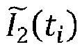
- I 1 ⁇ t i and Q 1 ⁇ t i are I/Q signals obtained by Hilbert transform on the I/Q signals I 1 (t i ) and Q 1 (t i ) after DC bias correction.
- phases ⁇ i ( t i ) and ⁇ q ( t i ) corresponding to the the I/Q signals I 2 (t i ) and Q 2 (t i ) are calculated by using Hilbert transform and the I/Q signals I 2 (t i ) and Q 2 (t i ) after amplitude imbalance correction, as shown in FIG.
- the mean value of the phase difference is -14 degrees.
- phase demodulation and phase unwrapping may be performed by using the above data after the I/Q signals imbalance correction are obtained so as to obtain a demodulation phase ⁇ and an amplitude Amp, thereby obtaining acoustic wavefield data.
- a demodulation phase curve and a demodulation phase difference curve before and after phase imbalance correction are as shown in FIG. 9 .
- Amplitude curves before and after phase imbalance correction are as shown in FIG. 10 .
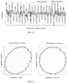
- I/Q crossplots before and after imbalance correction are as shown in FIG. 11 , and it can be seen that the crossplot is elliptical before correction and is circular after correction.
- IQ demodulation background noise before and after imbalance correction is as shown in FIG. 12 , and the noise level is reduced by 60% or above by the method of the present invention.
- IQ demodulation seismic wavefields before and after imbalance correction are as shown in FIG. 13 , and a signal-to-noise ratio is improved by 3-4 times by the method of the present invention.
- the present invention in a second aspect, provides a system for correcting imbalance in IQ demodulation of optical fiber DAS data.
- the system includes: an obtaining module, configured to obtain I/Q signals I 0 and Q 0 of each sampling on an optical fiber; a DC bias correction module, configured to perform DC bias correction on the I/Q signals I 0 and Q 0 to obtain I/Q signals I 1 and Q 1 after DC bias correction; an amplitude imbalance correction module, configured to perform amplitude imbalance correction on the I/Q signals I 1 and Q 1 after DC bias correction by using Hilbert transform to obtain I/Q signals I 2 and Q 2 after amplitude imbalance correction; and a phase imbalance correction module, configured to perform phase imbalance correction on the I/Q signals I 2 and Q 2 after amplitude imbalance correction by using Hilbert transform to obtain I/Q signals I 3 and Q 3 after phase imbalance correction.
Landscapes
- Physics & Mathematics (AREA)
- Engineering & Computer Science (AREA)
- General Physics & Mathematics (AREA)
- Mathematical Physics (AREA)
- Remote Sensing (AREA)
- Life Sciences & Earth Sciences (AREA)
- Mathematical Analysis (AREA)
- Theoretical Computer Science (AREA)
- Data Mining & Analysis (AREA)
- Pure & Applied Mathematics (AREA)
- Mathematical Optimization (AREA)
- Computational Mathematics (AREA)
- Environmental & Geological Engineering (AREA)
- Acoustics & Sound (AREA)
- General Life Sciences & Earth Sciences (AREA)
- Geology (AREA)
- Geophysics (AREA)
- Software Systems (AREA)
- Databases & Information Systems (AREA)
- Algebra (AREA)
- General Engineering & Computer Science (AREA)
- Power Engineering (AREA)
- Measurement Of Mechanical Vibrations Or Ultrasonic Waves (AREA)
- Digital Transmission Methods That Use Modulated Carrier Waves (AREA)
- Investigating Or Analyzing Materials By The Use Of Ultrasonic Waves (AREA)
- Optical Communication System (AREA)
Abstract
Description
- The present invention relates to the technical field of optical fiber sensing and seismic exploration, and particularly relates to a method and system for correcting imbalance in In-phase/Quadrature (I/Q, or IQ) demodulation of optical fiber DAS data.
- The optical fiber Distributed Acoustic Sensing (DAS) technology is a revolutionary new technology in which optical fiber is used as both a sensing medium and a transmission medium, and may sense acoustic vibration information around the optical fiber, and the acoustic vibration information is recorded by high-density time and space sampling. The DAS technology is widely applied in seismic data acquisition in wells, dam safety monitoring, perimeter security, pipe monitoring or other aspects. The DAS technology mainly utilizes Rayleigh backscattering (RBS) of laser when laser propagates through the optical fiber. RBS changes accordingly when a medium surrounding the optical fiber vibrates. Seismic wave information of the formation may be obtained by continuously observing and demodulating this optical signal.
- The DAS technology generally employs a phase-sensitive Optical Time Domain Reflectometer (ϕ-OTDR) to obtain RBS phase information by In-phase/Quadrature (I/Q, or IQ) phase demodulation. Due to the inherent errors of an optical fiber sensing device, such as direct current (DC) bias, amplitude imbalance and phase imbalance, output I/Q values vary elliptically on a crossplot, and a demodulation phase exhibits a non-linear relationship with a to-be-measured physical quantity, so that the phase demodulation accuracy is seriously affected, and the phase noise generated thereby is difficult to remove in subsequent signal processing. Therefore, how to achieve high-accuracy DAS phase demodulation becomes an important and difficult task constraining the development of this technology, and many experts at home and abroad work on eliminating such complex interference.
- The present invention provides a method and system for correcting imbalance in IQ demodulation of optical fiber DAS data for the technical problem in the prior art that phase noise is difficult to remove in signal processing. The method is employed to be capable of correcting I/Q signals accurately, suppressing optical fiber demodulation noise accurately and efficiently, and improving optical fiber DAS data acquisition quality.
- To achieve the above objective, the present invention, in a first aspect, provides a method for correcting imbalance in IQ demodulation of optical fiber DAS data, including the following steps: obtaining I/Q signals I0 and Q0 of each sampling on an optical fiber; performing DC bias correction on the I/Q signals I0 and Q0 to obtain I/Q signals I1 and Q1 after DC bias correction; performing amplitude imbalance correction on the I/Q signals I1 and Q1 after DC bias correction by using Hilbert transform to obtain I/Q signals I2 and Q2 after amplitude imbalance correction; and performing phase imbalance correction on the I/Q signals I2 and Q2 after amplitude imbalance correction by using Hilbert transform to obtain I/Q signals I3 and Q3 after phase imbalance correction.
- Optionally, wherein the step of performing DC bias correction on the I/Q signals I0 and Q0 to obtain I/Q signals I1 and Q1 after DC bias correction comprises: calculating corresponding DC bias factors Di and Dq according to the I/Q signals I0 and Q0; and performing DC bias correction on the I/Q signals I0 and Q0 by using the DC bias factors Di and Dq to obtain the I/Q signals I1 and Q1 after DC bias correction.
- Optionally, wherein the step of calculating corresponding DC bias factors Di and Dq according to the I/Q signals I0 and Q0 comprises: calculating the corresponding DC bias factors Di and Dq according to a mean value of the I/Q signals I0 and Q0 at different time.
- Optionally, wherein the step of performing amplitude imbalance correction on the I/Q signals I1 and Q1 after DC bias correction by using Hilbert transform to obtain I/Q signals I2 and Q2 after amplitude imbalance correction comprises: calculating corresponding amplitude imbalance factors Ai and Aq by using Hilbert transform and the I/Q signals I1 and Q1 after DC bias correction; and performing amplitude imbalance correction on the I/Q signals I1 and Q1 after DC bias correction according to the amplitude imbalance factors Ai and Aq to obtain the I/Q signals I2 and Q2 after amplitude imbalance correction.
- Optionally, wherein the step of calculating corresponding amplitude imbalance factors Ai and Aq by using Hilbert transform and the I/Q signals I1 and Q1 after DC bias correction comprises: calculating corresponding instantaneous amplitudes of the I/Q signals I1 and Q1 by Hilbert transform; and calculating the corresponding amplitude imbalance factors Ai and Aq according to a mean value of corresponding instantaneous amplitudes at different time.
- Optionally, wherein the step of performing phase imbalance correction on the I/Q signals I2 and Q2 after amplitude imbalance correction by using Hilbert transform to obtain I/Q signals I3 and Q3 after phase imbalance correction comprises: calculating phases ψi and ψq corresponding to the I/Q signals I2 and Q2 by using Hilbert transform and the I/Q signals I2 and Q2 after amplitude imbalance correction; calculating a phase imbalance factor θ according to the phases ψi and ψq corresponding to the I/Q signals I2 and Q2; and performing phase imbalance correction on the I/Q signals I2 and Q2 after amplitude imbalance correction according to the phase imbalance factor θ to obtain the I/Q signals I3 and Q3 after phase imbalance correction.
- Optionally, wherein the step of calculating phases ψi and ψq corresponding to the I/Q signals I2 and Q2 by using Hilbert transform and the I/Q signals I2 and Q2 after amplitude imbalance correction comprises: obtaining the corresponding phases ψi and ψq by an arctangent function of a ratio of the I/Q signals I2 and Q2 to the corresponding I/Q signals after Hilbert transform.
- Optionally, wherein the step of calculating a phase imbalance factor θ according to the phases ψi and ψq corresponding to the I/Q signals comprises: determining the phase imbalance factor θ by using a mean value of differences of the phases ψi and ψq at different time.
- Optionally, wherein performing phase imbalance correction on the I/Q signals I2 and Q2 after amplitude imbalance correction according to the phase imbalance factor θ by the following manner to obtain the I/Q signals I3 and Q3 after phase imbalance correction:


- The present invention, in a second aspect, provides a system for correcting imbalance in IQ demodulation of optical fiber DAS data, which is characterized by including: an obtaining module, configured to obtain I/Q signals I0 and Q0 of each sampling on an optical fiber; a DC bias correction module, configured to perform DC bias correction on the I/Q signals I0 and Q0 to obtain I/Q signals I1 and Q1 after DC bias correction; an amplitude imbalance correction module, configured to perform amplitude imbalance correction on the I/Q signals I1 and Q1 after DC bias correction by using Hilbert transform to obtain I/Q signals I2 and Q2 after amplitude imbalance correction; a phase imbalance correction module, configured to perform phase imbalance correction on the I/Q signals I2 and Q2 after amplitude imbalance correction by using Hilbert transform to obtain I/Q signals I3 and Q3 after phase imbalance correction.
- The present invention has at least the following technical effects by the technical solutions provided by the present invention:
According to the method for correcting imbalance in IQ demodulation of optical fiber DAS data, the I/Q signals I0 and Q0 of each sampling (i.e., observation point) on the optical fiber are obtained; DC bias correction is performed on the I/Q signals I0 and Q0 to obtain I/Q signals I1 and Q1 after DC bias correction; then, amplitude imbalance correction is performed on the I/Q signals I1 and Q1 after DC bias correction by using Hilbert transform to obtain I/Q signals I2 and Q2 after amplitude imbalance correction; and subsequently, phase imbalance correction is performed on the I/Q signals I2 and Q2 after amplitude imbalance correction by using Hilbert transform to obtain I/Q signals I3 and Q3 after phase imbalance correction. It is possible to perform accurate correction on I/Q signals, accurately and efficiently suppress optical fiber demodulation noise, and improve optical fiber DAS data acquisition quality by the method provided by the present invention. - Other features and advantages of the present invention will be described in detail in the detailed description of the embodiments below.
- The drawings are used to provide a further understanding of embodiments of the present invention and constitute a part of this specification, and to explain the embodiments of the present invention together with specific implementation modes, but do not limit the embodiments of the present invention. In the drawings:
-
FIG. 1 is a flowchart illustrating a method for correcting imbalance in IQ demodulation of optical fiber DAS data according to an embodiment of the present invention; -
FIG. 2 is a schematic diagram illustrating I/Q signals I0(t) and Q0(ti) at sample points when there is no external acoustic signal in a method for correcting imbalance in IQ demodulation of optical fiber DAS data according to an embodiment of the present invention; -
FIG. 3 is a schematic diagram illustrating I/Q signals I1(ti) and Q1(ti) after DC bias correction in a method for correcting imbalance in IQ demodulation of optical fiber DAS data according to an embodiment of the present invention; -
FIG. 4 is a schematic diagram illustrating I/Q signals I2(ti) and Q2(ti) after amplitude imbalance correction in a method for correcting imbalance in IQ demodulation of optical fiber DAS data according to an embodiment of the present invention; -
FIG. 5 is a schematic diagram illustrating a phase curve and a phase difference curve of I/Q signals obtained by Hilbert transform in a method for correcting imbalance in IQ demodulation of optical fiber DAS data according to an embodiment of the present invention; -
FIG. 6 is a schematic diagram illustrating I/Q signals I3(ti) and Q3(ti) after imbalance correction in a method for correcting imbalance in IQ demodulation of optical fiber DAS data according to an embodiment of the present invention; -
FIG. 7 is a zoomed view illustrating I/Q signals I2(ti) and Q2(ti) after amplitude imbalance correction in a method for correcting imbalance in IQ demodulation of optical fiber DAS data according to an embodiment of the present invention; -
FIG. 8 is a partially enlarged view illustrating I/Q signals I3(ti) and Q3(ti) after phase imbalance correction in a method for correcting imbalance in IQ demodulation of optical fiber DAS data according to an embodiment of the present invention; -
FIG. 9 is a schematic diagram illustrating a demodulation phase curve and a demodulation phase difference curve before and after imbalance correction in a method for correcting imbalance in IQ demodulation of optical fiber DAS data according to an embodiment of the present invention; -
FIG. 10 is a schematic diagram illustrating amplitude curves before and after imbalance correction in a method for correcting imbalance in IQ demodulation of optical fiber DAS data according to an embodiment of the present invention; -
FIG. 11 is a schematic diagram illustrating I/Q cross plots before and after imbalance correction in a method for correcting imbalance in IQ demodulation of optical fiber DAS data according to an embodiment of the present invention; -
FIG. 12 is a schematic diagram illustrating IQ demodulation background noise before and after imbalance correction in a method for correcting imbalance in IQ demodulation of optical fiber DAS data according to an embodiment of the present invention; -
Fig. 13 is a schematic diagram illustrating IQ demodulation seismic wavefields before and after imbalance correction in a method for correcting imbalance in IQ demodulation of optical fiber DAS data according to an embodiment of the present invention; and -
FIG. 14 is a schematic diagram illustrating a system for correcting imbalance in IQ demodulation of optical fiber DAS data according to an embodiment of the present invention. - The specific implementation modes of the embodiments of the present invention are described in detail below in combination with the drawings. It should be understood that the specific implementation modes described herein are only used for describing and explaining the embodiments of the present invention and are not used for limiting the embodiments of the present invention.
- The obtainment, storage, use, processing, or the like of data in the technical solutions of the present application comply with the relevant provisions of national laws and regulations.
- Referring to
FIG. 1 , the present invention, in a first aspect, provides a method for correcting imbalance in IQ demodulation of optical fiber DAS data, including the following steps. - S101: I/Q signals I0 and Q0 of each sampling on an optical fiber are obtained.
- Specifically, in an embodiment of the present invention, an optical fiber DAS acquisition instrument is connected to an optical fiber coupled to a to-be-measured object, and I/Q signals I0 and Q0 are output at each sampling on the optical fiber in the absence of external acoustic signals around the optical fiber in the case of emitting optical pulses at a certain frequency. The optical fiber DAS acquisition instrument is an instrument with a phase-sensitive optical time domain reflectometer (ϕ-OTDR) as a core. The I/Q signals are in-phase and quadrature signals, and it is assumed that there is no external acoustic signals near each sampling on the optical fiber.
- S102: DC bias correction is performed on the I/Q signals I0 and Q0 to obtain I/Q signals I1 and Q1 after DC bias correction.
- Further, the step that DC bias correction is performed on the I/Q signals I0 and Q0 to obtain I/Q signals I1 and Q1 after DC bias correction includes the following step: Corresponding DC bias factors Di and Dq are calculated according to a mean value of the I/Q signals I0 and Q0 at different time:


- DC bias correction is performed on the I/Q signals I0 and Q0 by using the DC bias factors Di and Dq to obtain the I/Q signals I1 and Q1 after DC bias correction:


- S103: Amplitude imbalance correction is performed on the I/Q signals I1 and Q1 after DC bias correction by using Hilbert transform to obtain I/Q signals I2 and Q2 after amplitude imbalance correction.
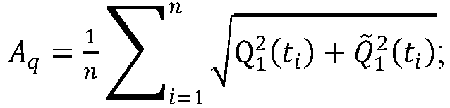
- Further, the step that amplitude imbalance correction is performed on the I/Q signals I1 and Q1 after DC bias correction by using Hilbert transform to obtain I/Q signals I2 and Q2 after amplitude imbalance correction includes the following steps: Corresponding instantaneous amplitudes of the I/Q signals I1 and Q1 are calculated by Hilbert transform; and Corresponding amplitude imbalance factors Ai and Aq are calculated according to a mean value of corresponding instantaneous amplitudes at different time:


- Amplitude imbalance correction is performed on the I/Q signals I1 and Q1 after DC bias correction according to the amplitude imbalance factors Ai and Aq to obtain the I/Q signals I2 and Q2 after amplitude imbalance correction:


- S104: Phase imbalance correction is performed on the I/Q signals I2 and Q2 after amplitude imbalance correction by using Hilbert transform to obtain I/Q signals I3 and Q3 after phase imbalance correction.
- Further, the step that phase imbalance correction is performed on the I/Q signals I2 and Q2 after amplitude imbalance correction by using Hilbert transform to obtain I/Q signals I3 and Q3 after imbalance correction includes the following steps: Corresponding phases ψi and ψq are obtained by an arctangent function of a ratio of the I/Q signals I2 and Q2 to the corresponding I/Q signals after Hilbert transform:


- A phase imbalance factor θ is determined by using a mean value of differences of the phases ψi and ψq at different time:

- Phase imbalance correction is performed on the I/Q signals I2(ti) and Q2(ti) after amplitude imbalance correction according to the phase imbalance factor θ to obtain I/Q signals I3(ti) and Q3(ti) after imbalance correction:


- Then, subsequent phase demodulation and phase unwrapping may be performed by using the above data to obtain a demodulation phase ω and an amplitude Amp, thereby obtaining acoustic wavefield data. The demodulation phase ω and the amplitude Amp are calculated as follows:


- In an embodiment of the present invention, the DC bias factors Di and Dq, the amplitude imbalance factors Ai and Aq, and the phase imbalance factor θ may be obtained by selecting positions without external acoustic signals uniformly after the I/Q signals I0 and Q0 at each sampling on the optical fiber are obtained, and then are applied to all acquired data at all samplings.
- A optical fiber DAS acquisition instrument is connected to an optical fiber hung in a cased well, in the case of emitting optical pulses at a repetition rate of 10K, I/Q signals I0(ti) and Q0(ti) output at time ti (i=1, 2, 3,...) at each sampling on the optical fiber without external acoustic signals around the optical fiber are acquired when a vibroseis is not excited, as shown in
FIG. 2 . - Corresponding DC bias factors Di and Dq are calculated according to a mean value of the I/Q signals I0(ti) and Q0(ti) at multiple points:


- DC bias correction is performed on the I/Q signals I0(tl) and Q0(ti) by using the DC bias factors Di and Dq to obtain I/Q signals I1(ti) and Q1(ti) after DC bias correction, as shown in
FIG. 3 :

- Then, corresponding amplitude imbalance factors Ai and Aq are calculated by using Hilbert transform and the I/Q signals I1(t) and Q1(t) after DC bias correction:



- Amplitude imbalance correction is performed on the I/Q signals I1(ti) and Q1(ti) after DC bias correction according to the amplitude imbalance factors Ai and Aq to obtain I/Q signals I2(ti) and Q2(ti) after amplitude imbalance correction, as shown in
FIG. 4 :

- Then, phases ψi (ti ) and ψq (ti ) corresponding to the the I/Q signals I2(ti) and Q2(ti) are calculated by using Hilbert transform and the I/Q signals I2(ti) and Q2(ti) after amplitude imbalance correction, as shown in
FIG. 5 :


- Referring to
FIG. 5 , a phase imbalance factor is calculated according to the phases ψi (ti ) and ψq (ti ) corresponding to the I/Q signals, and the I/Q signals themselves are quadrature signals, and have a phase difference

- In this embodiment, the mean value of the phase difference is -14 degrees.
- Phase imbalance correction is performed on the I/Q signals I2(ti) and Q2(ti) after amplitude imbalance correction according to the phase imbalance factor to obtain I/Q signals I3(ti) and Q3(ti) after imbalance correction, as shown in
FIGS. 6-8 , whereinFIG. 7 and FIG. 8 are zoomed views of the I/Q signals before and after phase imbalance correction:

- Subsequent phase demodulation and phase unwrapping may be performed by using the above data after the I/Q signals imbalance correction are obtained so as to obtain a demodulation phase ω and an amplitude Amp, thereby obtaining acoustic wavefield data. The demodulation phase ω and the amplitude Amp are calculated as follows:


- Referring to
FIG. 9-FIG. 12 , a demodulation phase curve and a demodulation phase difference curve before and after phase imbalance correction are as shown inFIG. 9 . Amplitude curves before and after phase imbalance correction are as shown inFIG. 10 . I/Q crossplots before and after imbalance correction are as shown inFIG. 11 , and it can be seen that the crossplot is elliptical before correction and is circular after correction. IQ demodulation background noise before and after imbalance correction is as shown inFIG. 12 , and the noise level is reduced by 60% or above by the method of the present invention. IQ demodulation seismic wavefields before and after imbalance correction are as shown inFIG. 13 , and a signal-to-noise ratio is improved by 3-4 times by the method of the present invention. - Referring to
FIG. 14 , the present invention, in a second aspect, provides a system for correcting imbalance in IQ demodulation of optical fiber DAS data. The system includes: an obtaining module, configured to obtain I/Q signals I0 and Q0 of each sampling on an optical fiber; a DC bias correction module, configured to perform DC bias correction on the I/Q signals I0 and Q0 to obtain I/Q signals I1 and Q1 after DC bias correction; an amplitude imbalance correction module, configured to perform amplitude imbalance correction on the I/Q signals I1 and Q1 after DC bias correction by using Hilbert transform to obtain I/Q signals I2 and Q2 after amplitude imbalance correction; and a phase imbalance correction module, configured to perform phase imbalance correction on the I/Q signals I2 and Q2 after amplitude imbalance correction by using Hilbert transform to obtain I/Q signals I3 and Q3 after phase imbalance correction. - The preferred embodiments of the present invention are described above in detail in combination with the drawings, but the present invention is not limited to the specific details in the above embodiments. Various simple variations can be made to the technical solutions of the present invention in the scope of the technical concept of the present invention, and these simple variations all fall within the protection scope of the present invention.
- In addition, it should be noted that the specific technical features described in the above specific embodiments can be combined in any appropriate mode under the non-contradictory condition, and various possible combination modes will not be described separately in order to avoid unnecessary repetition.
- Furthermore, various different embodiments of the present invention can also be combined optionally, and the combinations also should be regarded as the content disclosed by the present invention as long as the combinations do not violate the concept of the present invention.
Claims (10)
- A method for correcting imbalance in IQ demodulation of optical fiber DAS data, characterized in that comprising:obtaining I/Q signals I0 and Q0 of each sampling;performing DC bias correction on the I/Q signals I0 and Q0 to obtain I/Q signals I1 and Q1 after DC bias correction;performing amplitude imbalance correction on the I/Q signals I1 and Q1 after DC bias correction by using Hilbert transform to obtain I/Q signals h and Q2 after amplitude imbalance correction; andperforming phase imbalance correction on the I/Q signals I2 and Q2 after amplitude imbalance correction by using Hilbert transform to obtain I/Q signals I3 and Q3 after phase imbalance correction.
- The method according to claim 1, wherein the step of performing DC bias correction on the I/Q signals I0 and Q0 to obtain I/Q signals I1 and Q1 after DC bias correction comprises:calculating corresponding DC bias factors Di and Dq according to the I/Q signals I0 and Q0; andperforming DC bias correction on the I/Q signals I0 and Q0 by using the DC bias factors Di and Dq to obtain the I/Q signals I1 and Q1 after DC bias correction.
- The method according to claim 2, wherein the step of calculating corresponding DC bias factors Di and Dq according to the I/Q signals I0 and Q0 comprises:
calculating the corresponding DC bias factors Di and Dq according to a mean value of the I/Q signals I0 and Q0 at different time. - The method according to claim 1, wherein the step of performing amplitude imbalance correction on the I/Q signals I1 and Q1 after DC bias correction by using Hilbert transform to obtain I/Q signals I2 and Q2 after amplitude imbalance correction comprises:calculating corresponding amplitude imbalance factors Ai and Aq by using Hilbert transform and the I/Q signals I1 and Q1 after DC bias correction; andperforming amplitude imbalance correction on the I/Q signals I1 and Q1 after DC bias correction according to the amplitude imbalance factors Ai and Aq to obtain the I/Q signals I2 and Q2 after amplitude imbalance correction.
- The method according to claim 4, wherein the step of calculating corresponding amplitude imbalance factors Ai and Aq by using Hilbert transform and the I/Q signals I1 and Q1 after DC bias correction comprises:calculating corresponding instantaneous amplitudes of the I/Q signals I1 and Q1 by Hilbert transform; andcalculating the corresponding amplitude imbalance factors Ai and Aq according to a mean value of corresponding instantaneous amplitudes at different time.
- The method according to claim 1, wherein the step of performing phase imbalance correction on the I/Q signals I2 and Q2 after amplitude imbalance correction by using Hilbert transform to obtain I/Q signals I3 and Q3 after imbalance phase correction comprises:calculating phases ψi and ψq corresponding to the I/Q signals I2 and Q2 by using Hilbert transform and the I/Q signals I2 and Q2 after amplitude imbalance correction;calculating a phase imbalance factor θ according to the phases ψi and ψq corresponding to the I/Q signals I2 and Q2; andperforming phase imbalance correction on the I/Q signals I2 and Q2 after amplitude imbalance correction according to the phase imbalance factor θ to obtain the I/Q signals I3 and Q3 after phase imbalance correction.
- The method according to claim 6, wherein the step of calculating phases ψi and ψq corresponding to the I/Q signals I2 and Q2 by using Hilbert transform and the I/Q signals I2 and Q2 after amplitude imbalance correction comprises:
obtaining the corresponding phases ψi and ψq by an arctangent function of a ratio of the I/Q signals I2 and Q2 to the corresponding I/Q signals after Hilbert transform. - The method according to claim 6, wherein the step of calculating a phase imbalance factor θ according to the phases ψi and ψq corresponding to the I/Q signals comprises:
determining the phase imbalance factor θ by using a mean value of differences of the phases ψi and ψq at different time. - The method according to claim 6, wherein performing phase imbalance correction on the I/Q signals I2 and Q2 after amplitude imbalance correction according to the phase imbalance factor θ by the following manner to obtain the I/Q signals I3 and Q3 after phase imbalance correction:


- A system for correcting imbalance in IQ demodulation of optical fiber DAS data, characterized in that comprising:an obtaining module, configured to obtain I/Q signals I0 and Q0 of each sampling on an optical fiber;a DC bias correction module, configured to perform DC bias correction on the I/Q signals I0 and Q0 to obtain I/Q signals I1 and Q1 after DC bias correction;an amplitude imbalance correction module, configured to perform amplitude imbalance correction on the I/Q signals I1 and Q1 after DC bias correction by using Hilbert transform to obtain I/Q signals I2 and Q2 after amplitude imbalance correction; anda phase imbalance correction module, configured to perform phase imbalance correction on the I/Q signals I2 and Q2 after amplitude imbalance correction by using Hilbert transform to obtain I/Q signals I3 and Q3 after phase imbalance correction.
Applications Claiming Priority (2)
| Application Number | Priority Date | Filing Date | Title |
|---|---|---|---|
| CN202111645744.5A CN116429234B (en) | 2021-12-30 | 2021-12-30 | Method and system for correcting imbalance of orthogonal demodulation of optical fiber distributed acoustic wave sensing data |
| PCT/CN2022/102882 WO2023123968A1 (en) | 2021-12-30 | 2022-06-30 | Quadrature demodulation imbalance correction method and system for distributed fiber acoustic sensing data |
Publications (3)
| Publication Number | Publication Date |
|---|---|
| EP4343290A1 true EP4343290A1 (en) | 2024-03-27 |
| EP4343290A4 EP4343290A4 (en) | 2024-12-18 |
| EP4343290B1 EP4343290B1 (en) | 2026-04-29 |
Family
ID=86997365
Family Applications (1)
| Application Number | Title | Priority Date | Filing Date |
|---|---|---|---|
| EP22913257.6A Active EP4343290B1 (en) | 2021-12-30 | 2022-06-30 | Quadrature demodulation imbalance correction method and system for distributed fiber acoustic sensing data |
Country Status (4)
| Country | Link |
|---|---|
| US (1) | US20240337525A1 (en) |
| EP (1) | EP4343290B1 (en) |
| CN (1) | CN116429234B (en) |
| WO (1) | WO2023123968A1 (en) |
Families Citing this family (2)
| Publication number | Priority date | Publication date | Assignee | Title |
|---|---|---|---|---|
| CN119602876B (en) * | 2024-12-03 | 2025-11-11 | 深圳大学 | Demodulation method and demodulation device for optical fiber DAS (data acquisition system) |
| CN119687978B (en) * | 2025-02-24 | 2025-07-04 | 吉林大学 | Complex multimodal phase noise suppression method for phase-sensitive optical time domain reflectometry |
Family Cites Families (14)
| Publication number | Priority date | Publication date | Assignee | Title |
|---|---|---|---|---|
| JP3549963B2 (en) * | 1995-11-02 | 2004-08-04 | 三菱電機株式会社 | Digital radio receiver |
| US5705949A (en) * | 1996-09-13 | 1998-01-06 | U.S. Robotics Access Corp. | Compensation method for I/Q channel imbalance errors |
| GB2323502B (en) * | 1997-03-18 | 2002-03-27 | Ericsson Telefon Ab L M | Radio receiver |
| US7310387B2 (en) * | 2003-12-26 | 2007-12-18 | Electronics And Telecommunications Research Institute | Apparatus for compensating DC offsets, gain and phase imbalances between I-channel and Q-channel in quadrature transceiving system |
| US8014444B1 (en) * | 2007-10-30 | 2011-09-06 | Itt Manufacturing Enterprises, Inc. | System and method for DC offset, amplitude and phase imbalance correction for I and Q baseband calibration |
| GB201019117D0 (en) * | 2010-11-11 | 2010-12-29 | Fotech Solutions Ltd | Distributed optical fibre sensor |
| CN102437983B (en) * | 2011-10-27 | 2015-05-06 | 安徽省菲特科技股份有限公司 | Method and device for self-correcting emitting end I/Q modulation imbalance |
| JP6003418B2 (en) * | 2012-09-05 | 2016-10-05 | 日本電気株式会社 | Wireless communication device, wireless communication device IQ imbalance correction control method, and program thereof |
| CN104486272A (en) * | 2014-12-08 | 2015-04-01 | 大唐移动通信设备有限公司 | Feedback signal correcting method and device |
| CN105628174B (en) * | 2016-01-08 | 2018-12-11 | 中国人民解放军国防科学技术大学 | Fibre-optical F-P sensor vibration demodulating system and method based on polarization switching |
| CN105610760B (en) * | 2016-01-29 | 2018-11-16 | 深圳市极致汇仪科技有限公司 | Wireless comprehensive test instrument is to the unbalanced detection method of single carrier QPSK signal IQ |
| CN107063433B (en) * | 2017-04-28 | 2019-06-25 | 电子科技大学 | Phase-sensitive optical time domain reflectometer and its implementation based on Golay complementary series |
| US10601630B1 (en) * | 2019-06-10 | 2020-03-24 | Robert Dickerman | Quadrature signal imbalance estimation |
| CN111678584A (en) * | 2020-06-17 | 2020-09-18 | 珠海任驰光电科技有限公司 | Optical fiber vibration measurement device and method with light source frequency shift calibration auxiliary channel |
-
2021
- 2021-12-30 CN CN202111645744.5A patent/CN116429234B/en active Active
-
2022
- 2022-06-30 US US18/576,554 patent/US20240337525A1/en active Pending
- 2022-06-30 WO PCT/CN2022/102882 patent/WO2023123968A1/en not_active Ceased
- 2022-06-30 EP EP22913257.6A patent/EP4343290B1/en active Active
Also Published As
| Publication number | Publication date |
|---|---|
| CN116429234A (en) | 2023-07-14 |
| WO2023123968A1 (en) | 2023-07-06 |
| CN116429234B (en) | 2025-08-22 |
| EP4343290A4 (en) | 2024-12-18 |
| EP4343290B1 (en) | 2026-04-29 |
| US20240337525A1 (en) | 2024-10-10 |
Similar Documents
| Publication | Publication Date | Title |
|---|---|---|
| EP4343290A1 (en) | Quadrature demodulation imbalance correction method and system for distributed fiber acoustic sensing data | |
| CN116429236B (en) | Method and device for suppressing coherent fading noise of optical fiber sensing data | |
| EP4343291A1 (en) | Global phase quadrature demodulation method and apparatus for optical fiber sensing data | |
| CN108345039B (en) | A method for eliminating adjacent frequency harmonic interference in ground NMR data | |
| Bai et al. | Phase unwrapping method of Φ-OTDR system based on recursive-branch-cut algorithm | |
| WO2016101413A1 (en) | Method and device for determining error vector magnitude series parameter | |
| CN117309013A (en) | A demodulation method and system for interferometric optical fiber sensors | |
| EP4384782B1 (en) | Signal processing methods for an optical detection system | |
| Chen et al. | Influence of the order of phase differentiation and unwrapping on retrieval of temporal waveforms in phase-demodulated Φ-OTDR | |
| Liu et al. | Frequency-Shift Phase Generation Carrier Demodulation for Noise Reduction in ϕ-OTDR | |
| CN116416314B (en) | Method and device for calibrating depth of optical fiber in well | |
| CN118424350B (en) | Phase unwrapping error recovery method based on phase sensitive optical time domain reflectometer | |
| KR100758492B1 (en) | Frequency Estimation System Using Orthogonal Filter and Its Method | |
| US20120239329A1 (en) | Sagnac phase shift tracking method for fiber-optic gyroscopes | |
| CN119533634A (en) | A DAS phase unwrapping error suppression method based on RMDM-SPA | |
| CN119179117A (en) | Reservoir fluid identification method, system, device and readable storage medium | |
| CN111505736A (en) | Calibration method of underwater measuring device and underwater detection system | |
| Gerner et al. | Improving self‐noise estimates of broadband seismometers by 3D trace rotation | |
| CN120489418B (en) | Hammer force measurement method and system suitable for strain pile dynamic testing | |
| RU2845586C1 (en) | Method of capturing threshold measuring by beat signal distortions in ring laser | |
| CN112924415B (en) | Data processing method and system for laser methane telemetering equipment | |
| CN109916361A (en) | A kind of roundness measurement signal processing method without angular position information | |
| Wang et al. | A constraint-based approach to prevent phase unwrapping failures in Φ-OTDR sensing | |
| Zhong et al. | Advances in distributed fiber optic acoustic sensing technology based on linear distribution of phase change | |
| Xu et al. | Distributed acoustic sensing phase unwrapping compensation algorithm based on extreme point detection |
Legal Events
| Date | Code | Title | Description |
|---|---|---|---|
| STAA | Information on the status of an ep patent application or granted ep patent |
Free format text: STATUS: THE INTERNATIONAL PUBLICATION HAS BEEN MADE |
|
| PUAI | Public reference made under article 153(3) epc to a published international application that has entered the european phase |
Free format text: ORIGINAL CODE: 0009012 |
|
| STAA | Information on the status of an ep patent application or granted ep patent |
Free format text: STATUS: REQUEST FOR EXAMINATION WAS MADE |
|
| 17P | Request for examination filed |
Effective date: 20231219 |
|
| AK | Designated contracting states |
Kind code of ref document: A1 Designated state(s): AL AT BE BG CH CY CZ DE DK EE ES FI FR GB GR HR HU IE IS IT LI LT LU LV MC MK MT NL NO PL PT RO RS SE SI SK SM TR |
|
| A4 | Supplementary search report drawn up and despatched |
Effective date: 20241120 |
|
| RIC1 | Information provided on ipc code assigned before grant |
Ipc: G01D 5/353 20060101ALI20241114BHEP Ipc: G06F 17/14 20060101ALI20241114BHEP Ipc: G01V 1/22 20060101ALI20241114BHEP Ipc: H03D 3/00 20060101ALI20241114BHEP Ipc: G01H 9/00 20060101AFI20241114BHEP |
|
| DAV | Request for validation of the european patent (deleted) | ||
| DAX | Request for extension of the european patent (deleted) | ||
| STAA | Information on the status of an ep patent application or granted ep patent |
Free format text: STATUS: EXAMINATION IS IN PROGRESS |
|
| 17Q | First examination report despatched |
Effective date: 20250723 |
|
| GRAP | Despatch of communication of intention to grant a patent |
Free format text: ORIGINAL CODE: EPIDOSNIGR1 |
|
| STAA | Information on the status of an ep patent application or granted ep patent |
Free format text: STATUS: GRANT OF PATENT IS INTENDED |
|
| INTG | Intention to grant announced |
Effective date: 20260128 |
|
| GRAS | Grant fee paid |
Free format text: ORIGINAL CODE: EPIDOSNIGR3 |
|
| GRAA | (expected) grant |
Free format text: ORIGINAL CODE: 0009210 |
|
| STAA | Information on the status of an ep patent application or granted ep patent |
Free format text: STATUS: THE PATENT HAS BEEN GRANTED |
|
| AK | Designated contracting states |
Kind code of ref document: B1 Designated state(s): AL AT BE BG CH CY CZ DE DK EE ES FI FR GB GR HR HU IE IS IT LI LT LU LV MC MK MT NL NO PL PT RO RS SE SI SK SM TR |
|
| REG | Reference to a national code |
Ref country code: CH Ref legal event code: F10 Free format text: ST27 STATUS EVENT CODE: U-0-0-F10-F00 (AS PROVIDED BY THE NATIONAL OFFICE) Effective date: 20260429 |