EP4343056A1 - Disperger - Google Patents
Disperger Download PDFInfo
- Publication number
- EP4343056A1 EP4343056A1 EP23197874.3A EP23197874A EP4343056A1 EP 4343056 A1 EP4343056 A1 EP 4343056A1 EP 23197874 A EP23197874 A EP 23197874A EP 4343056 A1 EP4343056 A1 EP 4343056A1
- Authority
- EP
- European Patent Office
- Prior art keywords
- dispersing
- disperger
- pulp
- rotatable
- feed
- Prior art date
- Legal status (The legal status is an assumption and is not a legal conclusion. Google has not performed a legal analysis and makes no representation as to the accuracy of the status listed.)
- Granted
Links
Images
Classifications
-
- D—TEXTILES; PAPER
- D21—PAPER-MAKING; PRODUCTION OF CELLULOSE
- D21D—TREATMENT OF THE MATERIALS BEFORE PASSING TO THE PAPER-MAKING MACHINE
- D21D1/00—Methods of beating or refining; Beaters of the Hollander type
- D21D1/004—Methods of beating or refining including disperging or deflaking
-
- D—TEXTILES; PAPER
- D21—PAPER-MAKING; PRODUCTION OF CELLULOSE
- D21D—TREATMENT OF THE MATERIALS BEFORE PASSING TO THE PAPER-MAKING MACHINE
- D21D1/00—Methods of beating or refining; Beaters of the Hollander type
- D21D1/004—Methods of beating or refining including disperging or deflaking
- D21D1/006—Disc mills
-
- D—TEXTILES; PAPER
- D21—PAPER-MAKING; PRODUCTION OF CELLULOSE
- D21C—PRODUCTION OF CELLULOSE BY REMOVING NON-CELLULOSE SUBSTANCES FROM CELLULOSE-CONTAINING MATERIALS; REGENERATION OF PULPING LIQUORS; APPARATUS THEREFOR
- D21C9/00—After-treatment of cellulose pulp, e.g. of wood pulp, or cotton linters ; Treatment of dilute or dewatered pulp or process improvement taking place after obtaining the raw cellulosic material and not provided for elsewhere
- D21C9/08—Removal of fats, resins, pitch or waxes; Chemical or physical purification, i.e. refining, of crude cellulose by removing non-cellulosic contaminants, optionally combined with bleaching
-
- D—TEXTILES; PAPER
- D21—PAPER-MAKING; PRODUCTION OF CELLULOSE
- D21D—TREATMENT OF THE MATERIALS BEFORE PASSING TO THE PAPER-MAKING MACHINE
- D21D1/00—Methods of beating or refining; Beaters of the Hollander type
- D21D1/004—Methods of beating or refining including disperging or deflaking
- D21D1/006—Disc mills
- D21D1/008—Discs
-
- D—TEXTILES; PAPER
- D21—PAPER-MAKING; PRODUCTION OF CELLULOSE
- D21D—TREATMENT OF THE MATERIALS BEFORE PASSING TO THE PAPER-MAKING MACHINE
- D21D5/00—Purification of the pulp suspension by mechanical means; Apparatus therefor
-
- D—TEXTILES; PAPER
- D21—PAPER-MAKING; PRODUCTION OF CELLULOSE
- D21H—PULP COMPOSITIONS; PREPARATION THEREOF NOT COVERED BY SUBCLASSES D21C OR D21D; IMPREGNATING OR COATING OF PAPER; TREATMENT OF FINISHED PAPER NOT COVERED BY CLASS B31 OR SUBCLASS D21G; PAPER NOT OTHERWISE PROVIDED FOR
- D21H11/00—Pulp or paper, comprising cellulose or lignocellulose fibres of natural origin only
- D21H11/16—Pulp or paper, comprising cellulose or lignocellulose fibres of natural origin only modified by a particular after-treatment
Definitions
- the invention relates to a disperger and a method for dispersing pulp.
- Wastepaper and packaging material as a source of raw material to new fibre-based products has long traditions, and its importance has increased in these days in terms of environment, energy, and sustainability.
- Dispersing is one way to process different contaminants in the pulp to reduce the negative effects of the contaminants to the pulp and to the web forming in the paper or board machine. Dispersing of the pulp does not actually remove the contaminants from the pulp but in the dispersing the pulp is slushed or treated to diminish negative effects of the contaminants to a quality and a runnability of the pulp or to facilitate a removal of the contaminants in process stages following the dispersing.
- contaminants such as printing ink particles attached to the fibres are detached from the fibres and made smaller so that they can be easily removed from the pulp in a flotation stage following the dispersing or, alternatively, to prevent them being visible in a finished paper or board web at least by visual examination.
- Dispersing also sticky particles remaining in the pulp are broken up to prevent a formation of different contaminant aggregates which may have negative effects on the runnability of the pulp during the formation of the paper or board web and on the runnability of the formed paper or board web in the paper or board machine. Dispersing is not intended to cut or break the fibres but only to release fibres from the contaminants and to reduce particulate size of the contaminants.
- Some dispergers of prior art comprise coaxial oppositely positioned disperger elements having either disc-like or conical forms and having a stationary dispersing element, i.e., a stator, and a rotatable dispersing element, i.e., rotor, the rotor being arranged to be rotated relative to the fixed stator.
- the stator and the rotor comprise dispersing surfaces configured to subject a dispersing effect to the pulp to be dispersed.
- the pulp to be dispersed is fed into the disperger through a feed connection located on a front side of the disperger, the feed connection comprising a feed screw therein for intensifying the feed of the pulp into the disperger.
- An object of the present invention is to provide a novel disperger and a novel method for dispersing pulp.
- the invention is based on the idea of arranging a feed connection of the disperger, or two or more feed connections of the disperger in case of the disperger comprising at least two feed connections, at least partly between the dispersing elements and the rotating motor of the disperger.
- An advantage of the invention is a compact structure of the disperger with reduced length of the disperger when compared to prior art dispergers, thereby decreasing a space needed for the disperger.
- a further advantage is that a free space may be provided on a front-end side of the disperger, making it possible to arrange an easy access to the dispersing elements of the disperger.
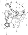
- Figure 1 is a schematic view of a disc-like disperger 1 as seen obliquely from above, the disperger 1 having a first end 1a, i.e., a front end 1a, and a second end 1b, i.e., a rear end 1b.
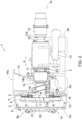
- Figure 2 is a schematic partial cross sectional side view of the disc-like disperger 1 of Figure 1 .
- the disperger 1 may be used for dispersing fibrous material, i.e., pulp, and typically pulp containing recycled fibres originating for example from wastepaper, recycled paperboard or packing board, or waste pulp.
- An intention of the dispersing is to treat the pulp so that contaminants are released from the fibres so that the contaminants can be easily removed from the pulp in a flotation stage following the dispersing or, alternatively, to prevent the contaminants being visible at least by visual examination in a finished paper or paperboard or other fibre product.
- Said contaminants include for example printing inks and surface coating agents, such as different stickies, waxes, adhesives, and pastes, remaining in the wastepaper, recycled paperboard or packing board, or waste pulp.
- the disperger 1 comprises a disperger frame 2, having a first end 2a, i.e., a front end 2a, on a side of the first end 1a of the disperger 1, and a second end 2b, i.e., a rear end 2b, on a side of the second end 1 of the disperger 1.
- a disperger housing 3 contributing to define a dispersing chamber 3' that is intended to accommodate dispersing elements that will subject a dispersing effect to the pulp to be dispersed.
- the disperger housing 3, and consequently the dispersing chamber 3' has a first end 3a, i.e., a front end 3a, on the side of the first end 2a of the frame 2 and a second end 3b, i.e., a rear end 3b, on the side of the second end 2b of the frame 2.
- the disperger 1 further comprises, in the dispersing chamber 3', a stationary, fixed disc-like dispersing element 4, i.e., a disc-like stator 4.
- the stator 4 comprises a number of, i.e., one or more, dispersing plates 5 for the stator 4.
- the dispersing plate/plates 5 is/are attached to the disperger frame 2 in the dispersing chamber 3', either directly or indirectly by an appropriate connecting piece.
- the disperger plate/plates 5 is/are detachable for replacing a worn or broken plate 5 with a new one.
- the disperger 1 further comprises, in the dispersing chamber 3', a rotatable disc-like dispersing element 6, i.e., a disc-like rotor 6.
- the rotor 6 comprises a hub 7 and a rotor disc 8 attached to the hub 7, the hub 7 and the rotor disc 8 together forming a frame of the rotor 6.
- the rotor 6 further comprises a number of, i.e., one or more, dispersing plates 9 for the rotor 6.
- the dispersing plate/plates 9 is/are attached to the rotor disc 8.
- the disperger plate/plates 9 is/are detachable for replacing a worn or broken plate 9 with a new one.
- stator 4 and the rotor 6 are arranged in the dispersing chamber 3' substantially opposite to each other such that there is a small gap between the stator 4 and the rotor 6.
- This small gap between the stator 4 and the rotor 6 forms a dispersing zone 10 of the disperger 1, wherein the dispersing effect subjected to the pulp to be dispersed takes place when the disperger 1 is in operation and the rotor 6 is rotated relative to the stator 4.
- the disperger plates 5, 9 comprise dispersing surfaces facing towards each other, i.e., facing towards the dispersing zone 10.
- the dispersing surfaces typically comprise projecting parts, such as teeth or the like, as well as cavities between the projecting parts.
- the cavities may be grooves but most often they are planar areas between the projecting parts.
- the disperger 1 further comprises a rotatable shaft 11 coupled to the rotor 6, in practice to the hub 7 of the rotor 6, and a rotating motor 12 coupled to the rotatable shaft 11 at the second end 1b of the disperger 1, the rotating motor 12 thus being coupled to the rotor 6 by the rotatable shaft 11.
- the rotating motor 12 is intended to rotate the rotor 6 relative to the stator 4 in a direction of arrow R, for instance, the arrow R thus indicating an intended rotation direction R of the rotor 6.
- the dispersing surface in the rotor 6 rotates relative to the dispersing surface in the stator 4 and the dispersing effect is subjected to the pulp to be dispersed in the dispersing zone 10 as discussed above.
- the disperger 1 may further comprise at least one loading device 13 that is coupled to the rotatable shaft 11.
- the at least one loading device 13 is arranged to move the rotatable shaft 11 in an axial direction thereof back and forth, as schematically shown by arrow A, for moving back and forth the rotor 6 attached to the shaft 11, i.e., by moving the rotor 6 either away from the stator 4 or towards the stator 4, for adjusting a size of the dispersing zone 10 between the stator 4 and the rotor 6.
- the axial direction of the rotatable shaft 11 may also be considered to disclose an axial direction of the disperger 1.
- the disperger 1 further comprises a feed connection 14 for feeding the pulp to be dispersed into the disperger 1.
- the feed connection 14 has a first end 14a for receiving the pulp to be dispersed, the first end 14a being intended to be connected to a pipeline (not shown) carrying the pulp to the disperger 1.
- the feed connection 14 has a second end 14b fitted inside the disperger 1 for feeding the received pulp into the disperger 1.
- a consistency of the pulp to be supplied into the disperger 1 is usually quite high, such as about 15 to 45%, preferably about 20 to 40%.
- the dispersing of the pulp is preferably carried out in high consistencies, because in low consistencies a freeness of the pulp decreases, leading to a decrease in an applicable running speed of the paper or board machine.
- the pulp already dispersed in the disperger 1 is discharged out of the disperger 1 through a discharge outlet 15.
- the shaft 11 has a first end 11a coupled to the rotor 6 and a second end 11b coupled to the rotating motor 12.
- the shaft 11 is supported with bearings 22 at its central part on the side rotating motor 12 relative to the feed connection 14.
- the shaft 11 is, however, at least from the feed connection 14 up to the first end 11a of the shaft 11 free from bearings, i.e., without comprising supporting bearings, or floating, so to speak, which simplifies the adjustment or control of the size of the dispersing zone 10 between the stator 4 and the rotor 6 by moving the rotor 6 either away from the stator 4 or towards the stator 4.
- the placement of the rotor 6 at the one end, i.e., the first end 11a, of the shaft 11 has also the effect of minimizing the length of the shaft 11 and the length of the disperger 1, correspondingly.
- a dilution water inlet 16 for supplying dilution water into the dispersing chamber 3' for decreasing the consistency of the pulp, for example to the consistency of about 4 to 10%, preferably to the consistency of about 6 to 8% and a discharge connection 17 for discharging the pulp dispersed in this lower consistency out the disperger 1.
- the discharge outlet 15 for discharging the pulp dispersed in the higher consistency is closed.
- the feed connection 14 is arranged between the dispersing elements 4, 6 and the rotating motor 12 of the disperger 1 such that both the first end 14a and the second end 14b of the feed connection 14 is located between the disperger elements 4, 6 and the rotating motor 12 in the direction from the first end 1a and the second end 1b of the disperger 1, i.e., in the axial direction of the disperger 1.
- the disclosed solution makes the structure of the disperger compact by decreasing the length of the disperger in view of prior art dispergers, thereby decreasing a space requirement for the disperger.
- the length of the disperger decreases because the feed screw and a drive thereof remaining on the front-end side of the prior art dispergers may be omitted.
- the disclosed disperger is simpler, cheaper and easier to maintain than the prior art dispergers.
- a further advantage of arranging the feed connection 14 between the dispersing elements 4, 6 and the rotating motor 12 is that a free space may easily be provided on the front-end side of the disperger 1, whereby an openable front-end plate 20 of the disperger housing 3 may be arranged at the front end 3a of the disperger housing 3 to allow an easy access into an interior of the dispersing chamber 3' for carrying out maintenance operations subjected to the stator 4 and the rotor 6, as discussed in more detail below.
- the pulp fed into the disperger 1 through the feed connection 14 is further fed towards the dispersing zone 10 in an axial direction of the rotatable shaft 11 through an opening 18 extending through the second end 3b of the disperger housing 3 and a centre part of the dispersing element remaining on the side of the second end 3b of the disperger housing 3, i.e., on the side of the second end 14b of the feed connection 14, that dispersing element being, in the embodiment of the Figures the stator 4 of the disperger 1.
- the pulp may be fed towards the dispersing zone 10 by an effect of pressure affecting in a piping that conveys the pulp to the disperger 1 but a feed screw 19 may be applied to intensify the feed of pulp towards the dispersing zone 10, as discussed in more detail below.
- the disperger 1 further comprises a feed screw 19 at the second end 14b of the feed connection 14.
- the feed screw 19 is arranged to extend from the feed connection 14 towards the dispersing zone 10 to intensify the flow of the pulp to be dispersed towards the dispersing zone 10 in the axial direction of the rotatable shaft 11 through the opening 18 extending through the second end 3b of the disperger housing 3 and the centre part of the stator 4.
- the feed screw 19 is coaxial with the rotatable shaft 11 and, in the embodiment of the Figures, the feed screw 19 is coupled to the rotor 6, and to be more exact, to the hub 7 of the rotor 6. Alternatively, or additionally, the feed screw 19 may be coupled to the rotatable shaft 11.
- the feed screw 19 When the feed screw 19 is coupled to the rotor 6 and/or to the rotatable shaft 11, the feed screw 19 is arranged to rotate in response to the rotation of the rotor 6 and the rotatable shaft 11, whereby the feed screw 19 intensifies the feed of the pulp received from the feed connection 14 towards the dispersing zone 10 through the opening 18. Because the feed screw 19 is coupled to the rotor 6 and/or to the rotatable shaft 11, a separate motor needed in prior art for operating the feed screw may now be omitted, which reduces the costs of the disperger. Further, to intensify the flow of the pulp into the dispersing zone 10, the hub 7 of the rotor 6 may be provided with a number of feeder plates 7' that assist in directing the flow of the pulp into the dispersing zone 10.
- stator 4 is arranged in the dispersing chamber 3' on the side of the feed connection, or in other words, on the side of the second end 3b of the disperger housing 3, and the dispersing plates 6 of the stator 4 are attached to an inner surface of the disperger housing 3 at the second end 3b thereof.
- the rotor 6 is arranged, in turn, on an opposite side of the dispersing chamber 3', or in other words, on the side of the first end 3a of the disperger housing 3.
- the feed screw 19 extends through the centre part of the stator 4 from the location of the second end 14b of the feed connection 14 substantially up to the dispersing zone 10 for feeding the pulp to be dispersed towards the dispersing zone 10.
- the stationary dispersing element is arranged to be closest to the at least one feed connection.
- a sealing of the dispersing chamber 3' is simpler than in an embodiment disclosed below, wherein a rotatable dispersing element is arranged on the side of the second end 3b of the disperger housing 3.
- the front-end plate 20 is opened, allowing the access into the dispersing chamber 3'. Thereafter the rotor 6 may be detached from the shaft 11 and removed outside from the dispersing chamber 3', thereby allowing an easy access to the dispersing plates 5, 9 of the stator 4 and the rotor 6.
- a special tool that may be integrated with or coupled to the disperger housing 3 may be applied for detaching the rotor 6 from the shaft 11 for removing the rotor 6 away from the front of the stator 4.
- the said tool is intended to be attached to the rotor 6 before detaching the rotor 6 from the shaft 11 and thereafter to support the rotor 6 detached from the shaft 11 until the rotor 6 is attached back to the shaft 11.
- One possible tool for that purpose is shown schematically in the Figures and denoted with reference sign 21.
- the rotor 6 is arranged in the dispersing chamber 3' on the side of the feed connection 14or in other words, on the side of the second end 3b of the disperger housing 3.
- the stator 4 is arranged, in turn, on an opposite side of the dispersing chamber 3', or in other words, on the side of the first end 3a of the disperger housing 3, whereby the dispersing plates 5 of the stator 4 may be attached to an inner surface of the openable front-end plate 20 of the disperger housing 3.
- the feed screw 19 extends from the location of the second end 14b of the feed connection 14 substantially up to the dispersing zone 10 for feeding the pulp to be dispersed towards the dispersing zone 10.
- the stationary dispersing element is arranged to be farthest away from the at least one feed connection.
- the feed screw 19 thus extends through the centre part of the rotor 6 from the location of the second end 14b of the feed connection 14 substantially up to the dispersing zone 10 for feeding the pulp to be dispersed towards the dispersing zone 10.
- the front-end plate 20 is opened, allowing the access into the dispersing chamber 3'. If the dispersing plates 5 of the stator 4 are attached to the inner surface of the openable front-end plate 20 of the disperger housing 3, the opening of the front-end plate 20 allows an immediate access to the dispersing plates 5 of the stator 4 as well as to the dispersing plates 9 of the rotor 6 without a need for any tool 21 or other arrangements or actions for removing the stator 4 away from the front of the rotor 6.
- disperger 1 there is only one single stationary dispersing element 4, i.e., the stator 4, and only one single rotatable dispersing element 6, i.e., a rotor 6, and thereby only one single dispersing zone 10 between the single stator 4 and the single rotor 6.
- the disclosed solution may also be applied in dispergers with two or more stators 4 and/or with two or more rotors 6, and therefore, consequently, in dispergers with two or more dispersing zones 10.
- the disclosed solution may be applied in a disperger comprising at least one stationary dispersing element and at least one rotatable dispersing element arranged substantially opposite to each other for forming a dispersing zone between each oppositely positioned stationary and rotatable dispersing elements, whereby the pulp may be subjected to the dispersing effect in one or more dispersing zones, depending on the number of the stators and the rotors in the disperger.
- the at least one feed connection is arranged in the disperger at least partly between the dispersing elements and the rotating motor, in the direction between the first end of the disperger and the second end of the dipserger, i.e., at least the second end of the at least one feed connection is between the dispersing elements and the rotating motor in the direction from the first end of the disperger towards the second end of the disperger.
- the solution and its embodiments are presented in a disc-like disperger comprising disc-like dispersing elements.
- the solution and its various embodiments disclosed above by possibly for example replacing the attachment of the stationary dispersing element to the end structures of the disperger housing with the attachment of the stationary dispersing element to an inner circumference of the disperger housing, may be applied correspondingly also in a conical disperger comprising conical dispersing elements.
Landscapes
- Engineering & Computer Science (AREA)
- Mechanical Engineering (AREA)
- Life Sciences & Earth Sciences (AREA)
- Wood Science & Technology (AREA)
- Paper (AREA)
Abstract
Description
- The invention relates to a disperger and a method for dispersing pulp.
- Recycling of wastepaper and packaging material as a source of raw material to new fibre-based products has long traditions, and its importance has increased in these days in terms of environment, energy, and sustainability.
- When paper or paperboard is manufactured from pulp, and especially from pulp containing recycled fibres originating for example from wastepaper, recycled paperboard or packing board, or waste pulp, it is an intention to process different contaminants in the pulp before a formation of a paper web or a board web so that negative effects of the contaminants to the pulp as well as to a web forming in a paper or board machine are reduced. Said contaminants include for example printing inks and surface coating agents, such as different stickies, waxes, adhesives, and pastes, remaining in the wastepaper, recycled cardboard or packing board, or waste pulp.
- Dispersing is one way to process different contaminants in the pulp to reduce the negative effects of the contaminants to the pulp and to the web forming in the paper or board machine. Dispersing of the pulp does not actually remove the contaminants from the pulp but in the dispersing the pulp is slushed or treated to diminish negative effects of the contaminants to a quality and a runnability of the pulp or to facilitate a removal of the contaminants in process stages following the dispersing. In the dispersing, among other things, contaminants such as printing ink particles attached to the fibres are detached from the fibres and made smaller so that they can be easily removed from the pulp in a flotation stage following the dispersing or, alternatively, to prevent them being visible in a finished paper or board web at least by visual examination. In the dispersing also sticky particles remaining in the pulp are broken up to prevent a formation of different contaminant aggregates which may have negative effects on the runnability of the pulp during the formation of the paper or board web and on the runnability of the formed paper or board web in the paper or board machine. Dispersing is not intended to cut or break the fibres but only to release fibres from the contaminants and to reduce particulate size of the contaminants.
- Some dispergers of prior art comprise coaxial oppositely positioned disperger elements having either disc-like or conical forms and having a stationary dispersing element, i.e., a stator, and a rotatable dispersing element, i.e., rotor, the rotor being arranged to be rotated relative to the fixed stator. The stator and the rotor comprise dispersing surfaces configured to subject a dispersing effect to the pulp to be dispersed. The pulp to be dispersed is fed into the disperger through a feed connection located on a front side of the disperger, the feed connection comprising a feed screw therein for intensifying the feed of the pulp into the disperger.
- An object of the present invention is to provide a novel disperger and a novel method for dispersing pulp.
- The invention is characterized by the features of the independent claims.
- The invention is based on the idea of arranging a feed connection of the disperger, or two or more feed connections of the disperger in case of the disperger comprising at least two feed connections, at least partly between the dispersing elements and the rotating motor of the disperger.
- An advantage of the invention is a compact structure of the disperger with reduced length of the disperger when compared to prior art dispergers, thereby decreasing a space needed for the disperger. A further advantage is that a free space may be provided on a front-end side of the disperger, making it possible to arrange an easy access to the dispersing elements of the disperger.
- Some embodiments of the invention are disclosed in the dependent claims.
- In the following the invention will be described in greater detail by means of preferred embodiments with reference to the accompanying drawings, in which
-
Figure 1 shows schematically a disc-like disperger as seen obliquely from above, and -
Figure 2 is a schematic partial cross-sectional side view of the disc-like disperger ofFigure 1 . - For the sake of clarity, the figures show some embodiments of the invention in a simplified manner. Like reference signs identify like elements in the figures.
-
Figure 1 is a schematic view of a disc-like disperger 1 as seen obliquely from above, the disperger 1 having afirst end 1a, i.e., afront end 1a, and asecond end 1b, i.e., arear end 1b.Figure 2 is a schematic partial cross sectional side view of the disc-like disperger 1 ofFigure 1 . The disperger 1 may be used for dispersing fibrous material, i.e., pulp, and typically pulp containing recycled fibres originating for example from wastepaper, recycled paperboard or packing board, or waste pulp. An intention of the dispersing is to treat the pulp so that contaminants are released from the fibres so that the contaminants can be easily removed from the pulp in a flotation stage following the dispersing or, alternatively, to prevent the contaminants being visible at least by visual examination in a finished paper or paperboard or other fibre product. Said contaminants include for example printing inks and surface coating agents, such as different stickies, waxes, adhesives, and pastes, remaining in the wastepaper, recycled paperboard or packing board, or waste pulp. - The disperger 1 comprises a
disperger frame 2, having afirst end 2a, i.e., afront end 2a, on a side of thefirst end 1a of the disperger 1, and asecond end 2b, i.e., arear end 2b, on a side of the second end 1 of the disperger 1. At thefirst end 2a of theframe 2 there is adisperger housing 3 contributing to define a dispersing chamber 3' that is intended to accommodate dispersing elements that will subject a dispersing effect to the pulp to be dispersed. The disperger housing 3, and consequently the dispersing chamber 3', has afirst end 3a, i.e., afront end 3a, on the side of thefirst end 2a of theframe 2 and asecond end 3b, i.e., arear end 3b, on the side of thesecond end 2b of theframe 2. - The disperger 1 further comprises, in the dispersing chamber 3', a stationary, fixed disc-like dispersing element 4, i.e., a disc-like stator 4. The stator 4 comprises a number of, i.e., one or more, dispersing plates 5 for the stator 4. The dispersing plate/plates 5 is/are attached to the
disperger frame 2 in the dispersing chamber 3', either directly or indirectly by an appropriate connecting piece. The disperger plate/plates 5 is/are detachable for replacing a worn or broken plate 5 with a new one. - The disperger 1 further comprises, in the dispersing chamber 3', a rotatable disc-like dispersing element 6, i.e., a disc-like rotor 6. The rotor 6 comprises a
hub 7 and a rotor disc 8 attached to thehub 7, thehub 7 and the rotor disc 8 together forming a frame of the rotor 6. The rotor 6 further comprises a number of, i.e., one or more, dispersingplates 9 for the rotor 6. The dispersing plate/plates 9 is/are attached to the rotor disc 8. The disperger plate/plates 9 is/are detachable for replacing a worn orbroken plate 9 with a new one. - The stator 4 and the rotor 6 are arranged in the dispersing chamber 3' substantially opposite to each other such that there is a small gap between the stator 4 and the rotor 6. This small gap between the stator 4 and the rotor 6 forms a
dispersing zone 10 of the disperger 1, wherein the dispersing effect subjected to the pulp to be dispersed takes place when the disperger 1 is in operation and the rotor 6 is rotated relative to the stator 4. - The
disperger plates 5, 9 comprise dispersing surfaces facing towards each other, i.e., facing towards the dispersingzone 10. The dispersing surfaces typically comprise projecting parts, such as teeth or the like, as well as cavities between the projecting parts. The cavities may be grooves but most often they are planar areas between the projecting parts. When the rotor 6 is rotated relative to the stator 4, the projecting parts in the dispersing surfaces of the stator 4 and the rotor 6 cause impacts to the pulp to be dispersed, these impacts causing, together with effects of internal friction in the pulp, the contaminant particles to detach from the fibres and break down into smaller pieces. Various implementations of the dispersing surfaces are well known for a person skilled in the art and therefore they are not considered in more detail herein. - The disperger 1 further comprises a
rotatable shaft 11 coupled to the rotor 6, in practice to thehub 7 of the rotor 6, and a rotatingmotor 12 coupled to therotatable shaft 11 at thesecond end 1b of the disperger 1, the rotatingmotor 12 thus being coupled to the rotor 6 by therotatable shaft 11. The rotatingmotor 12 is intended to rotate the rotor 6 relative to the stator 4 in a direction of arrow R, for instance, the arrow R thus indicating an intended rotation direction R of the rotor 6. In response to the rotation of the rotor 6 the dispersing surface in the rotor 6 rotates relative to the dispersing surface in the stator 4 and the dispersing effect is subjected to the pulp to be dispersed in thedispersing zone 10 as discussed above. - The disperger 1 may further comprise at least one
loading device 13 that is coupled to therotatable shaft 11. The at least oneloading device 13 is arranged to move therotatable shaft 11 in an axial direction thereof back and forth, as schematically shown by arrow A, for moving back and forth the rotor 6 attached to theshaft 11, i.e., by moving the rotor 6 either away from the stator 4 or towards the stator 4, for adjusting a size of thedispersing zone 10 between the stator 4 and the rotor 6. The axial direction of therotatable shaft 11 may also be considered to disclose an axial direction of the disperger 1. - The disperger 1 further comprises a
feed connection 14 for feeding the pulp to be dispersed into the disperger 1. Thefeed connection 14 has afirst end 14a for receiving the pulp to be dispersed, thefirst end 14a being intended to be connected to a pipeline (not shown) carrying the pulp to the disperger 1. Thefeed connection 14 has asecond end 14b fitted inside the disperger 1 for feeding the received pulp into the disperger 1. A consistency of the pulp to be supplied into the disperger 1 is usually quite high, such as about 15 to 45%, preferably about 20 to 40%. The dispersing of the pulp is preferably carried out in high consistencies, because in low consistencies a freeness of the pulp decreases, leading to a decrease in an applicable running speed of the paper or board machine. The pulp already dispersed in the disperger 1 is discharged out of the disperger 1 through adischarge outlet 15. - The
shaft 11 has afirst end 11a coupled to the rotor 6 and asecond end 11b coupled to the rotatingmotor 12. Theshaft 11 is supported withbearings 22 at its central part on theside rotating motor 12 relative to thefeed connection 14. Theshaft 11 is, however, at least from thefeed connection 14 up to thefirst end 11a of theshaft 11 free from bearings, i.e., without comprising supporting bearings, or floating, so to speak, which simplifies the adjustment or control of the size of the dispersingzone 10 between the stator 4 and the rotor 6 by moving the rotor 6 either away from the stator 4 or towards the stator 4. The placement of the rotor 6 at the one end, i.e., thefirst end 11a, of theshaft 11 has also the effect of minimizing the length of theshaft 11 and the length of the disperger 1, correspondingly. - In the embodiment of the Figures, there is also a
dilution water inlet 16 for supplying dilution water into the dispersing chamber 3' for decreasing the consistency of the pulp, for example to the consistency of about 4 to 10%, preferably to the consistency of about 6 to 8% and adischarge connection 17 for discharging the pulp dispersed in this lower consistency out the disperger 1. When the pulp dispersed in the lower consistency is discharged out of the disperger 1, thedischarge outlet 15 for discharging the pulp dispersed in the higher consistency is closed. - In the embodiment of the Figures, the
feed connection 14 is arranged between the dispersing elements 4, 6 and therotating motor 12 of the disperger 1 such that both thefirst end 14a and thesecond end 14b of thefeed connection 14 is located between the disperger elements 4, 6 and therotating motor 12 in the direction from thefirst end 1a and thesecond end 1b of the disperger 1, i.e., in the axial direction of the disperger 1. Other arrangements, wherein at least thesecond end 14b of thefeed connection 14 is in the disperger 1 between the dispersing elements 4, 6 and therotating motor 12 so that the pulp received through thefirst end 14b of thefeed connection 14 is discharged into thedisperger 14 between the disperger elements 4, 6 and therotating motor 12 through thesecond end 14 thefeed connection 14, are possible. - The disclosed solution makes the structure of the disperger compact by decreasing the length of the disperger in view of prior art dispergers, thereby decreasing a space requirement for the disperger. The length of the disperger decreases because the feed screw and a drive thereof remaining on the front-end side of the prior art dispergers may be omitted. The disclosed disperger is simpler, cheaper and easier to maintain than the prior art dispergers.
- A further advantage of arranging the
feed connection 14 between the dispersing elements 4, 6 and therotating motor 12 is that a free space may easily be provided on the front-end side of the disperger 1, whereby an openable front-end plate 20 of thedisperger housing 3 may be arranged at thefront end 3a of thedisperger housing 3 to allow an easy access into an interior of the dispersing chamber 3' for carrying out maintenance operations subjected to the stator 4 and the rotor 6, as discussed in more detail below. - The pulp fed into the disperger 1 through the
feed connection 14 is further fed towards the dispersingzone 10 in an axial direction of therotatable shaft 11 through anopening 18 extending through thesecond end 3b of thedisperger housing 3 and a centre part of the dispersing element remaining on the side of thesecond end 3b of thedisperger housing 3, i.e., on the side of thesecond end 14b of thefeed connection 14, that dispersing element being, in the embodiment of the Figures the stator 4 of the disperger 1. According to an embodiment the pulp may be fed towards the dispersingzone 10 by an effect of pressure affecting in a piping that conveys the pulp to the disperger 1 but afeed screw 19 may be applied to intensify the feed of pulp towards the dispersingzone 10, as discussed in more detail below. - According to the embodiment of the Figures, the disperger 1 further comprises a
feed screw 19 at thesecond end 14b of thefeed connection 14. Thefeed screw 19 is arranged to extend from thefeed connection 14 towards the dispersingzone 10 to intensify the flow of the pulp to be dispersed towards the dispersingzone 10 in the axial direction of therotatable shaft 11 through theopening 18 extending through thesecond end 3b of thedisperger housing 3 and the centre part of the stator 4. Thefeed screw 19 is coaxial with therotatable shaft 11 and, in the embodiment of the Figures, thefeed screw 19 is coupled to the rotor 6, and to be more exact, to thehub 7 of the rotor 6. Alternatively, or additionally, thefeed screw 19 may be coupled to therotatable shaft 11. When thefeed screw 19 is coupled to the rotor 6 and/or to therotatable shaft 11, thefeed screw 19 is arranged to rotate in response to the rotation of the rotor 6 and therotatable shaft 11, whereby thefeed screw 19 intensifies the feed of the pulp received from thefeed connection 14 towards the dispersingzone 10 through theopening 18. Because thefeed screw 19 is coupled to the rotor 6 and/or to therotatable shaft 11, a separate motor needed in prior art for operating the feed screw may now be omitted, which reduces the costs of the disperger. Further, to intensify the flow of the pulp into the dispersingzone 10, thehub 7 of the rotor 6 may be provided with a number of feeder plates 7' that assist in directing the flow of the pulp into the dispersingzone 10. - In the embodiment of the Figures the stator 4 is arranged in the dispersing chamber 3' on the side of the feed connection, or in other words, on the side of the
second end 3b of thedisperger housing 3, and the dispersing plates 6 of the stator 4 are attached to an inner surface of thedisperger housing 3 at thesecond end 3b thereof. The rotor 6 is arranged, in turn, on an opposite side of the dispersing chamber 3', or in other words, on the side of thefirst end 3a of thedisperger housing 3. Thefeed screw 19 extends through the centre part of the stator 4 from the location of thesecond end 14b of thefeed connection 14 substantially up to the dispersingzone 10 for feeding the pulp to be dispersed towards the dispersingzone 10. Generally, in the embodiment disclosed herein, of all the dispersing elements of the disperger the stationary dispersing element is arranged to be closest to the at least one feed connection. When a stationary dispersing element is arranged on the side of thesecond end 3b of thedisperger housing 3, a sealing of the dispersing chamber 3' is simpler than in an embodiment disclosed below, wherein a rotatable dispersing element is arranged on the side of thesecond end 3b of thedisperger housing 3. - During the maintenance operation of the disperger 1 of the Figures, and especially during the maintenance operations subjected to the stator 4 and the rotor 6 in the dispersing chamber 3', the front-
end plate 20 is opened, allowing the access into the dispersing chamber 3'. Thereafter the rotor 6 may be detached from theshaft 11 and removed outside from the dispersing chamber 3', thereby allowing an easy access to the dispersingplates 5, 9 of the stator 4 and the rotor 6. A special tool that may be integrated with or coupled to thedisperger housing 3 may be applied for detaching the rotor 6 from theshaft 11 for removing the rotor 6 away from the front of the stator 4. The said tool is intended to be attached to the rotor 6 before detaching the rotor 6 from theshaft 11 and thereafter to support the rotor 6 detached from theshaft 11 until the rotor 6 is attached back to theshaft 11. One possible tool for that purpose is shown schematically in the Figures and denoted withreference sign 21. - According to another embodiment that is not disclosed in the drawings, the rotor 6 is arranged in the dispersing chamber 3' on the side of the feed connection 14or in other words, on the side of the
second end 3b of thedisperger housing 3. The stator 4 is arranged, in turn, on an opposite side of the dispersing chamber 3', or in other words, on the side of thefirst end 3a of thedisperger housing 3, whereby the dispersing plates 5 of the stator 4 may be attached to an inner surface of the openable front-end plate 20 of thedisperger housing 3. In this embodiment thefeed screw 19 extends from the location of thesecond end 14b of thefeed connection 14 substantially up to the dispersingzone 10 for feeding the pulp to be dispersed towards the dispersingzone 10. Generally, in the embodiment disclosed herein, of all the dispersing elements of the disperger the stationary dispersing element is arranged to be farthest away from the at least one feed connection. In this embodiment, thefeed screw 19 thus extends through the centre part of the rotor 6 from the location of thesecond end 14b of thefeed connection 14 substantially up to the dispersingzone 10 for feeding the pulp to be dispersed towards the dispersingzone 10. - During the maintenance operation of the disperger of that kind of embodiment, and especially during the maintenance operations subjected to the stator 4 and the rotor 6 in the dispersing chamber 3', the front-
end plate 20 is opened, allowing the access into the dispersing chamber 3'. If the dispersing plates 5 of the stator 4 are attached to the inner surface of the openable front-end plate 20 of thedisperger housing 3, the opening of the front-end plate 20 allows an immediate access to the dispersing plates 5 of the stator 4 as well as to the dispersingplates 9 of the rotor 6 without a need for anytool 21 or other arrangements or actions for removing the stator 4 away from the front of the rotor 6. - In the disperger 1 disclosed above there is only one single stationary dispersing element 4, i.e., the stator 4, and only one single rotatable dispersing element 6, i.e., a rotor 6, and thereby only one
single dispersing zone 10 between the single stator 4 and the single rotor 6. However, the disclosed solution may also be applied in dispergers with two or more stators 4 and/or with two or more rotors 6, and therefore, consequently, in dispergers with two ormore dispersing zones 10. Furthermore, in the disperger 1 disclosed above, there is only asingle feed connection 14 but the disperger may also comprise two ormore feed connections 14. Thus, generally, the disclosed solution may be applied in a disperger comprising at least one stationary dispersing element and at least one rotatable dispersing element arranged substantially opposite to each other for forming a dispersing zone between each oppositely positioned stationary and rotatable dispersing elements, whereby the pulp may be subjected to the dispersing effect in one or more dispersing zones, depending on the number of the stators and the rotors in the disperger. In the dispergers like that, the at least one feed connection is arranged in the disperger at least partly between the dispersing elements and the rotating motor, in the direction between the first end of the disperger and the second end of the dipserger, i.e., at least the second end of the at least one feed connection is between the dispersing elements and the rotating motor in the direction from the first end of the disperger towards the second end of the disperger. - Furthermore, in the description above, the solution and its embodiments are presented in a disc-like disperger comprising disc-like dispersing elements. However, the solution and its various embodiments disclosed above, by possibly for example replacing the attachment of the stationary dispersing element to the end structures of the disperger housing with the attachment of the stationary dispersing element to an inner circumference of the disperger housing, may be applied correspondingly also in a conical disperger comprising conical dispersing elements.
- It will be obvious to a person skilled in the art that, as the technology advances, the inventive concept can be implemented in various ways. The invention and its embodiments are not limited to the examples described above but may vary within the scope of the claims.
Claims (12)
- A disc-like disperger (1) for dispersing pulp, the disperger (1) comprisingat least one stationary disc-like dispersing element (4) and at least one rotatable disc-like dispersing element (6) arranged substantially opposite to each other for forming a dispersing zone (10) between each oppositely positioned stationary (4) and rotatable (6) dispersing elements, in which dispersing zone (10) a dispersing effect is subjected to the pulp to be dispersed,a rotatable shaft (11) coupled to the at least one rotatable dispersing element (6) and a rotating motor (12) coupled to the rotatable shaft (11) for rotating the at least one rotatable dispersing element (6),at least one feed connection (14) for feeding the pulp to be dispersed into the disperger (1),characterized in thatthe at least one feed connection (14) is arranged in the disperger (1) at least partly between the dispersing elements (4, 6) and the rotating motor (12), andthe disperger (1) comprises a feed screw (19) arranged to extend from the at least one feed connection (14) towards the at least one dispersing zone (10).
- A disperger as claimed in claim 1, characterized in thatthe at least one feed connection (14) comprises a first end (14a) for receiving the pulp to be dispersed and a second end (14b) for discharging the pulp into the disperger (1), and thatat least the second end (14b) of the at least one feed connection (14) is in the disperger (1) between the dispersing elements (4, 6) and the rotating motor (12).
- A disperger as claimed in claim 1 or 2, characterized in that
the feed screw (19) is coaxial with the rotatable shaft (11) and arranged around at least one of the following: a hub (7) of the at least one rotatable dispersing element (6) and the rotatable shaft (11). - A disperger as claimed in claim 3, characterized in that
the feed screw (19) is coupled to the at least one of the following: the hub (7) of the at least one rotatable dispersing element (6) and the rotatable shaft (11), whereby the feed screw (19) is arranged to rotate in response to a rotation of the at least one rotatable dispersing element (6) and to feed the pulp received from the at least one feed connection (14) towards the at least one dispersing zone (10). - The disperger as claimed in any one of the preceding claims, characterized in that
the disperger (1) comprises a disperger housing (3) contributing to define a dispersing chamber (3') arranged to accommodate the dispersing elements (4, 6), the disperger housing (3) comprising a first end (3a) facing away from the at least one feed connection (14) and a second end (3b) facing towards the at least one feed connection (14), and that the first end (3a) of the disperger housing (3) comprises an openable front-end plate (20) allowing an access into the disperger housing (3). - A disperger as claimed in any one of the preceding claims, characterized in that
of all the dispersing elements (4, 6) of the disperger (1) a stationary dispersing element (4) is arranged to be closest to the at least one feed connection (14). - A disperger as claimed in claims 5 or 6, characterized in that
the said stationary dispersing element (4) is arranged in the dispersing chamber (3') at the second end (3b) of the disperger housing (3). - A disperger as claimed in any one of claims 1 to 5, characterized in that
of all the dispersing elements (4, 6) a stationary dispersing element (4) is arranged to be farthest away from the at least one feed connection (14). - A disperger as claimed in claims 5 and 8, characterized in that
the said stationary dispersing element (4) is arranged in the dispersing chamber (3') at the openable front-end plate (20) of the disperger housing (3). - A method for dispersing pulp in a disc-like disperger (1) that comprisesat least one stationary disc-like dispersing element (4) and at least one rotatable disc-like dispersing element (6) arranged substantially opposite to each other for forming a dispersing zone (10) between each oppositely positioned stationary (4) and rotatable (6) dispersing elements, in which dispersing zone (10) a dispersing effect is subjected to the pulp to be dispersed,a rotatable shaft (11) coupled to the at least one rotatable dispersing element (6) and a rotating motor (12) coupled to the rotatable shaft (11) for rotating the at least one rotatable dispersing element (6),at least one feed connection (14) for feeding the pulp to be dispersed into the disperger (1),characterized byfeeding the pulp to be dispersed into the disperger (1) between the dispersing elements (4, 6) and the rotating motor (12), and byfeeding the pulp fed into the disperger (1) towards the at least one dispersing zone (10) in an axial direction of the rotatable shaft (11) by a feed screw (19) arranged to extend from the at least one feed connection (14) towards the at least one dispersing zone (10).
- A method as claimed in claim 10, characterized by feeding the pulp fed into the disperger (1) towards the at least one dispersing zone (10) by a feed screw (19) coupled to the at least one of the following: a hub (7) of the at least one rotatable dispersing element (6) and the rotatable shaft (11), whereby the feed screw (19) is arranged to rotate in response to a rotation of the at least one rotatable dispersing element (6) and to feed the pulp received from the at least one feed connection (14) towards the at least one dispersing zone (10).
- A method as claimed in claim 10 or 11, characterized by a consistency of the pulp to be fed into the disperger (1) being about 15 to 45%, preferably about 20 to 40%.
Applications Claiming Priority (1)
| Application Number | Priority Date | Filing Date | Title |
|---|---|---|---|
| FI20225817A FI131183B1 (en) | 2022-09-21 | 2022-09-21 | Dispersants |
Publications (2)
| Publication Number | Publication Date |
|---|---|
| EP4343056A1 true EP4343056A1 (en) | 2024-03-27 |
| EP4343056B1 EP4343056B1 (en) | 2025-03-19 |
Family
ID=88093579
Family Applications (1)
| Application Number | Title | Priority Date | Filing Date |
|---|---|---|---|
| EP23197874.3A Active EP4343056B1 (en) | 2022-09-21 | 2023-09-18 | Disperger |
Country Status (2)
| Country | Link |
|---|---|
| EP (1) | EP4343056B1 (en) |
| FI (1) | FI131183B1 (en) |
Citations (2)
| Publication number | Priority date | Publication date | Assignee | Title |
|---|---|---|---|---|
| DE3808765A1 (en) * | 1988-03-16 | 1989-09-28 | Voith Gmbh J M | Apparatus for the dispersion and disintegration of fibrous material |
| EP1147805A1 (en) * | 2000-04-13 | 2001-10-24 | Voith Paper Patent GmbH | Process to disperse a paper fibers slurry and plant for using the process |
-
2022
- 2022-09-21 FI FI20225817A patent/FI131183B1/en active
-
2023
- 2023-09-18 EP EP23197874.3A patent/EP4343056B1/en active Active
Patent Citations (2)
| Publication number | Priority date | Publication date | Assignee | Title |
|---|---|---|---|---|
| DE3808765A1 (en) * | 1988-03-16 | 1989-09-28 | Voith Gmbh J M | Apparatus for the dispersion and disintegration of fibrous material |
| EP1147805A1 (en) * | 2000-04-13 | 2001-10-24 | Voith Paper Patent GmbH | Process to disperse a paper fibers slurry and plant for using the process |
Also Published As
| Publication number | Publication date |
|---|---|
| FI131183B1 (en) | 2024-11-25 |
| EP4343056B1 (en) | 2025-03-19 |
| FI20225817A1 (en) | 2024-03-22 |
Similar Documents
| Publication | Publication Date | Title |
|---|---|---|
| US5564572A (en) | Method and apparatus for screening waste paper pulp | |
| EP3927882B1 (en) | Device for mechanically processing lignocellulose-containing fibrous material | |
| FI67580B (en) | FOERFARANDE OCH ANORDNING FOER FIBRERING SILNING OCH PUMPNING AV CELLULOSAMASSA OCH RETURPAPPER | |
| US3735873A (en) | Apparatus for screening aqueous suspensions, preferably fiber stock and/or fiber-pulp suspensions | |
| EP4343056B1 (en) | Disperger | |
| EP1184509B2 (en) | Screening apparatus for fiber suspension | |
| CA2037045C (en) | Method and apparatus for pressurized refining of lignocellulose material | |
| EP1882773B1 (en) | Screen apparatus | |
| EP1454008B1 (en) | Method of separating colouring agents, particularly printing ink,from recycled fibre material | |
| US20060186235A1 (en) | Method for refining paper or cellulose fibers in an aqueous suspension | |
| US9370779B2 (en) | Method and arrangement | |
| US12129599B2 (en) | Pressure screen for a fiber web product process with removable cover | |
| FI67579C (en) | FOERFARANDE OCH ANORDNING FOER FIBRERING OCH PUMPNING AV CELLULOSAMASSA OCH RETURPAPPER | |
| EP1381731B1 (en) | Production of fiber suspension from waste paper | |
| EP4575080A1 (en) | Disperger with a dilution system | |
| US4222817A (en) | Method and apparatus for pulping and grading waste material | |
| CN1955373B (en) | Apparatus for preparing fiber pulp | |
| EP4644605B1 (en) | Pulper rotor | |
| FI57983B (en) | FOERFARANDE FOER ATT RAFFINERA OCH DEFIBRERA FIBERMASSA SAMT EN DEFIBRATOR ATT ANVAENDAS HAERVID | |
| EP4484641A2 (en) | Horizontal pulper | |
| JP7845620B2 (en) | Disc-type rotor and method for repairing a disc-type rotor | |
| FI105699B (en) | Method and use for the treatment of pulp from paper or paper mills | |
| JPH06313285A (en) | Method for pulping waste paper | |
| WO1996032591A2 (en) | Pump for conveying a moist pulp | |
| JPS62268891A (en) | Paper stock beating screen |
Legal Events
| Date | Code | Title | Description |
|---|---|---|---|
| PUAI | Public reference made under article 153(3) epc to a published international application that has entered the european phase |
Free format text: ORIGINAL CODE: 0009012 |
|
| STAA | Information on the status of an ep patent application or granted ep patent |
Free format text: STATUS: THE APPLICATION HAS BEEN PUBLISHED |
|
| AK | Designated contracting states |
Kind code of ref document: A1 Designated state(s): AL AT BE BG CH CY CZ DE DK EE ES FI FR GB GR HR HU IE IS IT LI LT LU LV MC ME MK MT NL NO PL PT RO RS SE SI SK SM TR |
|
| STAA | Information on the status of an ep patent application or granted ep patent |
Free format text: STATUS: REQUEST FOR EXAMINATION WAS MADE |
|
| 17P | Request for examination filed |
Effective date: 20240719 |
|
| RBV | Designated contracting states (corrected) |
Designated state(s): AL AT BE BG CH CY CZ DE DK EE ES FI FR GB GR HR HU IE IS IT LI LT LU LV MC ME MK MT NL NO PL PT RO RS SE SI SK SM TR |
|
| GRAJ | Information related to disapproval of communication of intention to grant by the applicant or resumption of examination proceedings by the epo deleted |
Free format text: ORIGINAL CODE: EPIDOSDIGR1 |
|
| GRAP | Despatch of communication of intention to grant a patent |
Free format text: ORIGINAL CODE: EPIDOSNIGR1 |
|
| GRAP | Despatch of communication of intention to grant a patent |
Free format text: ORIGINAL CODE: EPIDOSNIGR1 |
|
| STAA | Information on the status of an ep patent application or granted ep patent |
Free format text: STATUS: GRANT OF PATENT IS INTENDED |
|
| RIC1 | Information provided on ipc code assigned before grant |
Ipc: D21D 1/00 20060101AFI20240926BHEP |
|
| INTG | Intention to grant announced |
Effective date: 20241010 |
|
| GRAS | Grant fee paid |
Free format text: ORIGINAL CODE: EPIDOSNIGR3 |
|
| GRAA | (expected) grant |
Free format text: ORIGINAL CODE: 0009210 |
|
| STAA | Information on the status of an ep patent application or granted ep patent |
Free format text: STATUS: THE PATENT HAS BEEN GRANTED |
|
| AK | Designated contracting states |
Kind code of ref document: B1 Designated state(s): AL AT BE BG CH CY CZ DE DK EE ES FI FR GB GR HR HU IE IS IT LI LT LU LV MC ME MK MT NL NO PL PT RO RS SE SI SK SM TR |
|
| REG | Reference to a national code |
Ref country code: GB Ref legal event code: FG4D |
|
| REG | Reference to a national code |
Ref country code: CH Ref legal event code: EP |
|
| REG | Reference to a national code |
Ref country code: IE Ref legal event code: FG4D |
|
| REG | Reference to a national code |
Ref country code: DE Ref legal event code: R096 Ref document number: 602023002485 Country of ref document: DE |
|
| REG | Reference to a national code |
Ref country code: SE Ref legal event code: TRGR |
|
| PG25 | Lapsed in a contracting state [announced via postgrant information from national office to epo] |
Ref country code: RS Free format text: LAPSE BECAUSE OF FAILURE TO SUBMIT A TRANSLATION OF THE DESCRIPTION OR TO PAY THE FEE WITHIN THE PRESCRIBED TIME-LIMIT Effective date: 20250619 |
|
| PG25 | Lapsed in a contracting state [announced via postgrant information from national office to epo] |
Ref country code: FI Free format text: LAPSE BECAUSE OF FAILURE TO SUBMIT A TRANSLATION OF THE DESCRIPTION OR TO PAY THE FEE WITHIN THE PRESCRIBED TIME-LIMIT Effective date: 20250319 |
|
| REG | Reference to a national code |
Ref country code: LT Ref legal event code: MG9D |
|
| PG25 | Lapsed in a contracting state [announced via postgrant information from national office to epo] |
Ref country code: NO Free format text: LAPSE BECAUSE OF FAILURE TO SUBMIT A TRANSLATION OF THE DESCRIPTION OR TO PAY THE FEE WITHIN THE PRESCRIBED TIME-LIMIT Effective date: 20250619 |
|
| PG25 | Lapsed in a contracting state [announced via postgrant information from national office to epo] |
Ref country code: HR Free format text: LAPSE BECAUSE OF FAILURE TO SUBMIT A TRANSLATION OF THE DESCRIPTION OR TO PAY THE FEE WITHIN THE PRESCRIBED TIME-LIMIT Effective date: 20250319 |
|
| PG25 | Lapsed in a contracting state [announced via postgrant information from national office to epo] |
Ref country code: LV Free format text: LAPSE BECAUSE OF FAILURE TO SUBMIT A TRANSLATION OF THE DESCRIPTION OR TO PAY THE FEE WITHIN THE PRESCRIBED TIME-LIMIT Effective date: 20250319 |
|
| PG25 | Lapsed in a contracting state [announced via postgrant information from national office to epo] |
Ref country code: BG Free format text: LAPSE BECAUSE OF FAILURE TO SUBMIT A TRANSLATION OF THE DESCRIPTION OR TO PAY THE FEE WITHIN THE PRESCRIBED TIME-LIMIT Effective date: 20250319 Ref country code: GR Free format text: LAPSE BECAUSE OF FAILURE TO SUBMIT A TRANSLATION OF THE DESCRIPTION OR TO PAY THE FEE WITHIN THE PRESCRIBED TIME-LIMIT Effective date: 20250620 |
|
| REG | Reference to a national code |
Ref country code: NL Ref legal event code: MP Effective date: 20250319 |
|
| PG25 | Lapsed in a contracting state [announced via postgrant information from national office to epo] |
Ref country code: NL Free format text: LAPSE BECAUSE OF FAILURE TO SUBMIT A TRANSLATION OF THE DESCRIPTION OR TO PAY THE FEE WITHIN THE PRESCRIBED TIME-LIMIT Effective date: 20250319 |
|
| PG25 | Lapsed in a contracting state [announced via postgrant information from national office to epo] |
Ref country code: SM Free format text: LAPSE BECAUSE OF FAILURE TO SUBMIT A TRANSLATION OF THE DESCRIPTION OR TO PAY THE FEE WITHIN THE PRESCRIBED TIME-LIMIT Effective date: 20250319 |
|
| PG25 | Lapsed in a contracting state [announced via postgrant information from national office to epo] |
Ref country code: ES Free format text: LAPSE BECAUSE OF FAILURE TO SUBMIT A TRANSLATION OF THE DESCRIPTION OR TO PAY THE FEE WITHIN THE PRESCRIBED TIME-LIMIT Effective date: 20250319 Ref country code: PT Free format text: LAPSE BECAUSE OF FAILURE TO SUBMIT A TRANSLATION OF THE DESCRIPTION OR TO PAY THE FEE WITHIN THE PRESCRIBED TIME-LIMIT Effective date: 20250721 |
|
| PGFP | Annual fee paid to national office [announced via postgrant information from national office to epo] |
Ref country code: DE Payment date: 20250919 Year of fee payment: 3 |
|
| PG25 | Lapsed in a contracting state [announced via postgrant information from national office to epo] |
Ref country code: PL Free format text: LAPSE BECAUSE OF FAILURE TO SUBMIT A TRANSLATION OF THE DESCRIPTION OR TO PAY THE FEE WITHIN THE PRESCRIBED TIME-LIMIT Effective date: 20250319 Ref country code: IT Free format text: LAPSE BECAUSE OF FAILURE TO SUBMIT A TRANSLATION OF THE DESCRIPTION OR TO PAY THE FEE WITHIN THE PRESCRIBED TIME-LIMIT Effective date: 20250319 |
|
| PGFP | Annual fee paid to national office [announced via postgrant information from national office to epo] |
Ref country code: AT Payment date: 20251020 Year of fee payment: 3 |
|
| PGFP | Annual fee paid to national office [announced via postgrant information from national office to epo] |
Ref country code: SE Payment date: 20250918 Year of fee payment: 3 |
|
| PG25 | Lapsed in a contracting state [announced via postgrant information from national office to epo] |
Ref country code: CZ Free format text: LAPSE BECAUSE OF FAILURE TO SUBMIT A TRANSLATION OF THE DESCRIPTION OR TO PAY THE FEE WITHIN THE PRESCRIBED TIME-LIMIT Effective date: 20250319 Ref country code: EE Free format text: LAPSE BECAUSE OF FAILURE TO SUBMIT A TRANSLATION OF THE DESCRIPTION OR TO PAY THE FEE WITHIN THE PRESCRIBED TIME-LIMIT Effective date: 20250319 |
|
| PG25 | Lapsed in a contracting state [announced via postgrant information from national office to epo] |
Ref country code: RO Free format text: LAPSE BECAUSE OF FAILURE TO SUBMIT A TRANSLATION OF THE DESCRIPTION OR TO PAY THE FEE WITHIN THE PRESCRIBED TIME-LIMIT Effective date: 20250319 |
|
| PG25 | Lapsed in a contracting state [announced via postgrant information from national office to epo] |
Ref country code: SK Free format text: LAPSE BECAUSE OF FAILURE TO SUBMIT A TRANSLATION OF THE DESCRIPTION OR TO PAY THE FEE WITHIN THE PRESCRIBED TIME-LIMIT Effective date: 20250319 |
|
| PG25 | Lapsed in a contracting state [announced via postgrant information from national office to epo] |
Ref country code: IS Free format text: LAPSE BECAUSE OF FAILURE TO SUBMIT A TRANSLATION OF THE DESCRIPTION OR TO PAY THE FEE WITHIN THE PRESCRIBED TIME-LIMIT Effective date: 20250719 |
|
| REG | Reference to a national code |
Ref country code: DE Ref legal event code: R097 Ref document number: 602023002485 Country of ref document: DE |
|
| PG25 | Lapsed in a contracting state [announced via postgrant information from national office to epo] |
Ref country code: DK Free format text: LAPSE BECAUSE OF FAILURE TO SUBMIT A TRANSLATION OF THE DESCRIPTION OR TO PAY THE FEE WITHIN THE PRESCRIBED TIME-LIMIT Effective date: 20250319 |
|
| PLBE | No opposition filed within time limit |
Free format text: ORIGINAL CODE: 0009261 |
|
| STAA | Information on the status of an ep patent application or granted ep patent |
Free format text: STATUS: NO OPPOSITION FILED WITHIN TIME LIMIT |
|
| REG | Reference to a national code |
Ref country code: CH Ref legal event code: L10 Free format text: ST27 STATUS EVENT CODE: U-0-0-L10-L00 (AS PROVIDED BY THE NATIONAL OFFICE) Effective date: 20260128 |
|
| 26N | No opposition filed |
Effective date: 20251222 |