EP4342630A1 - State management program and state management method - Google Patents
State management program and state management method Download PDFInfo
- Publication number
- EP4342630A1 EP4342630A1 EP21940688.1A EP21940688A EP4342630A1 EP 4342630 A1 EP4342630 A1 EP 4342630A1 EP 21940688 A EP21940688 A EP 21940688A EP 4342630 A1 EP4342630 A1 EP 4342630A1
- Authority
- EP
- European Patent Office
- Prior art keywords
- eyeglasses lens
- machining apparatus
- check
- check operation
- eyeglasses
- Prior art date
- Legal status (The legal status is an assumption and is not a legal conclusion. Google has not performed a legal analysis and makes no representation as to the accuracy of the status listed.)
- Pending
Links
Images



Classifications
-
- G—PHYSICS
- G05—CONTROLLING; REGULATING
- G05B—CONTROL OR REGULATING SYSTEMS IN GENERAL; FUNCTIONAL ELEMENTS OF SUCH SYSTEMS; MONITORING OR TESTING ARRANGEMENTS FOR SUCH SYSTEMS OR ELEMENTS
- G05B19/00—Program-control systems
- G05B19/02—Program-control systems electric
- G05B19/18—Numerical control [NC], i.e. automatically operating machines, in particular machine tools, e.g. in a manufacturing environment, so as to execute positioning, movement or co-ordinated operations by means of program data in numerical form
- G05B19/4097—Numerical control [NC], i.e. automatically operating machines, in particular machine tools, e.g. in a manufacturing environment, so as to execute positioning, movement or co-ordinated operations by means of program data in numerical form characterised by using design data to control NC machines, e.g. CAD/CAM
-
- B—PERFORMING OPERATIONS; TRANSPORTING
- B24—GRINDING; POLISHING
- B24B—MACHINES, DEVICES, OR PROCESSES FOR GRINDING OR POLISHING; DRESSING OR CONDITIONING OF ABRADING SURFACES; FEEDING OF GRINDING, POLISHING, OR LAPPING AGENTS
- B24B49/00—Measuring or gauging equipment for controlling the feed movement of the grinding tool or work; Arrangements of indicating or measuring equipment, e.g. for indicating the start of the grinding operation
- B24B49/02—Measuring or gauging equipment for controlling the feed movement of the grinding tool or work; Arrangements of indicating or measuring equipment, e.g. for indicating the start of the grinding operation according to the instantaneous size and required size of the workpiece acted upon, the measuring or gauging being continuous or intermittent
-
- B—PERFORMING OPERATIONS; TRANSPORTING
- B24—GRINDING; POLISHING
- B24B—MACHINES, DEVICES, OR PROCESSES FOR GRINDING OR POLISHING; DRESSING OR CONDITIONING OF ABRADING SURFACES; FEEDING OF GRINDING, POLISHING, OR LAPPING AGENTS
- B24B9/00—Machines or devices designed for grinding edges or bevels on work or for removing burrs; Accessories therefor
- B24B9/02—Machines or devices designed for grinding edges or bevels on work or for removing burrs; Accessories therefor characterised by a special design with respect to properties of materials specific to articles to be ground
- B24B9/06—Machines or devices designed for grinding edges or bevels on work or for removing burrs; Accessories therefor characterised by a special design with respect to properties of materials specific to articles to be ground of non-metallic inorganic material, e.g. stone, ceramics, porcelain
- B24B9/08—Machines or devices designed for grinding edges or bevels on work or for removing burrs; Accessories therefor characterised by a special design with respect to properties of materials specific to articles to be ground of non-metallic inorganic material, e.g. stone, ceramics, porcelain of glass
- B24B9/14—Machines or devices designed for grinding edges or bevels on work or for removing burrs; Accessories therefor characterised by a special design with respect to properties of materials specific to articles to be ground of non-metallic inorganic material, e.g. stone, ceramics, porcelain of glass of optical work, e.g. lenses, prisms
- B24B9/148—Machines or devices designed for grinding edges or bevels on work or for removing burrs; Accessories therefor characterised by a special design with respect to properties of materials specific to articles to be ground of non-metallic inorganic material, e.g. stone, ceramics, porcelain of glass of optical work, e.g. lenses, prisms electrically, e.g. numerically, controlled
-
- G—PHYSICS
- G05—CONTROLLING; REGULATING
- G05B—CONTROL OR REGULATING SYSTEMS IN GENERAL; FUNCTIONAL ELEMENTS OF SUCH SYSTEMS; MONITORING OR TESTING ARRANGEMENTS FOR SUCH SYSTEMS OR ELEMENTS
- G05B19/00—Program-control systems
- G05B19/02—Program-control systems electric
- G05B19/18—Numerical control [NC], i.e. automatically operating machines, in particular machine tools, e.g. in a manufacturing environment, so as to execute positioning, movement or co-ordinated operations by means of program data in numerical form
- G05B19/406—Numerical control [NC], i.e. automatically operating machines, in particular machine tools, e.g. in a manufacturing environment, so as to execute positioning, movement or co-ordinated operations by means of program data in numerical form characterised by monitoring or safety
-
- G—PHYSICS
- G05—CONTROLLING; REGULATING
- G05B—CONTROL OR REGULATING SYSTEMS IN GENERAL; FUNCTIONAL ELEMENTS OF SUCH SYSTEMS; MONITORING OR TESTING ARRANGEMENTS FOR SUCH SYSTEMS OR ELEMENTS
- G05B19/00—Program-control systems
- G05B19/02—Program-control systems electric
- G05B19/418—Total factory control, i.e. centrally controlling a plurality of machines, e.g. direct or distributed numerical control [DNC], flexible manufacturing systems [FMS], integrated manufacturing systems [IMS] or computer integrated manufacturing [CIM]
- G05B19/41875—Total factory control, i.e. centrally controlling a plurality of machines, e.g. direct or distributed numerical control [DNC], flexible manufacturing systems [FMS], integrated manufacturing systems [IMS] or computer integrated manufacturing [CIM] characterised by quality surveillance of production
-
- G—PHYSICS
- G05—CONTROLLING; REGULATING
- G05B—CONTROL OR REGULATING SYSTEMS IN GENERAL; FUNCTIONAL ELEMENTS OF SUCH SYSTEMS; MONITORING OR TESTING ARRANGEMENTS FOR SUCH SYSTEMS OR ELEMENTS
- G05B2219/00—Program-control systems
- G05B2219/30—Nc systems
- G05B2219/45—Nc applications
- G05B2219/45157—Grind optical lens
Definitions
- the present disclosure relates to a state management program and a state management method for managing a state of an eyeglasses lens machining apparatus.
- an eyeglasses lens machining apparatus that performs machining on an eyeglasses lens is widely used in an eyeglasses lens shop and the like.
- an eyeglasses lens machining apparatus described in Patent Literature 1 holds an eyeglasses lens by attaching a lens holding shaft to a cup attached to the eyeglasses lens.
- the eyeglasses lens machining apparatus can perform machining a peripheral edge of the held eyeglasses lens with a peripheral edge machining tool.
- the eyeglasses lens machining apparatus described in Patent Literature 1 can form a hole at the held eyeglasses lens with a drilling tool.
- Patent Literature 1 JP2018-004930A
- an operation defect occurs in the eyeglasses lens machining apparatus
- appropriate measures for example, repair, replacement of components, change of settings, and the like
- a content of the operation defect on the eyeglasses lens machining apparatus even when the contents of the operation defects that occur are the same, causes of the operation defects are different from each other, in many cases.
- a skilled person who is familiar with management of the eyeglasses lens machining apparatus can reduce the man-hours and a time when the measures are actually performed, for example, by inquiring about a situation of the apparatus in advance, checking information indicating an operation of the apparatus in advance, or the like. Meanwhile, in the current situation, when the skilled person cannot be involved, there is a high frequency with which appropriate measures are not performed on the eyeglasses lens machining apparatus.
- a typical object of the present disclosure is to provide a state management program and a state management method capable of appropriately managing a state of an eyeglasses lens machining apparatus.
- a state management program executed by a control apparatus that controls an eyeglasses lens machining apparatus in order to manage a state of the eyeglasses lens machining apparatus, the state management program causing the control apparatus, by causing a control unit of the control apparatus to execute the state management program, to perform: a check operation execution step of causing the eyeglasses lens machining apparatus to execute a check operation for checking a state of the eyeglasses lens machining apparatus; and a result output step of outputting information indicating a result of the executed check operation.
- a state management method performed by a control apparatus that controls an eyeglasses lens machining apparatus in order to manage a state of the eyeglasses lens machining apparatus, the state management method including: a check operation execution step of causing the eyeglasses lens machining apparatus to execute a check operation for checking a state of the eyeglasses lens machining apparatus; and a result output step of outputting information indicating a result of the executed check operation.
- a state management method of an eyeglasses lens machining apparatus which is performed in an eyeglasses lens machining system including the eyeglasses lens machining apparatus that machines an eyeglasses lens and an information processing apparatus that enables to acquire information related to the eyeglasses lens machining apparatus, the state management method including: a check operation execution step in which the eyeglasses lens machining apparatus executes a check operation for checking a state; a result output step in which the eyeglasses lens machining apparatus outputs result information indicating a result of the executed check operation; and an analysis step in which the information processing apparatus acquires the result information output in the result output step, and analyzes the acquired result information by using an analysis tool constructed in advance.
- a state of the eyeglasses lens machining apparatus is appropriately managed.
- the state management program described in the present disclosure is executed by the control apparatus that controls the eyeglasses lens machining apparatus to manage the state of the eyeglasses lens machining apparatus.
- the control unit of the control apparatus performs the check operation execution step and the result output step.
- the check operation execution step the control unit causes the eyeglasses lens machining apparatus to execute the check operation for checking the state of the eyeglasses lens machining apparatus.
- the result output step the control unit outputs the information indicating the result of the executed check operation.
- the check operation for checking the state of the eyeglasses lens machining apparatus is executed by the eyeglasses lens machining apparatus, and the information indicating the result of the check operation is output. Therefore, it becomes easy to estimate the state of the eyeglasses lens machining apparatus (for example, a cause of operation defect or the like) based on the result of the check operation. Therefore, it becomes easier to perform appropriate processing on the eyeglasses lens machining apparatus.
- the check operation in the present disclosure is an operation executed to check the state of the eyeglasses lens machining apparatus with as high accuracy as possible.
- the check operation is executed by the eyeglasses lens machining apparatus to check the cause of the operation defect that has a possibility of occurring in the eyeglasses lens machining apparatus in more detail.
- the check operation may be an operation (that is, a dedicated operation for state check) executed separately from the operation (for example, at least one of a machining operation, a measurement operation, a communication operation, and the like) that is actually necessary to be executed to fit the eyeglasses lens into a frame.
- the cause of the operation defect is estimated more appropriately.
- at least a part of the check operation may include an operation actually performed to fit the eyeglasses lens in the frame (for example, a machining operation executed on the eyeglasses lens, and the like).
- the control apparatus that controls the operation of the eyeglasses lens machining apparatus may be the eyeglasses lens machining apparatus itself, or may be another device (for example, a PC or the like) connected to the eyeglasses lens machining apparatus. That is, the device that executes the eyeglasses lens machining control program according to the present disclosure is not limited to the eyeglasses lens machining apparatus. In addition, the control units of a plurality of devices may cooperate to execute the eyeglasses lens machining control program.
- the control unit may further execute an operation defect information acquisition step.
- operation defect information acquisition step operation defect information indicating a content of an operation defect in the eyeglasses lens machining apparatus is acquired.
- operation check execution step a check operation for checking a cause of the operation defect indicated by the acquired operation defect information may be executed.
- the cause of the operation defect of the eyeglasses lens machining apparatus for example, an operation defect that actually occurs in the eyeglasses lens machining apparatus, an operation defect that has a possibility of occurring in the eyeglasses lens machining apparatus, or the like
- the cause of the operation defect of the eyeglasses lens machining apparatus for example, an operation defect that actually occurs in the eyeglasses lens machining apparatus, an operation defect that has a possibility of occurring in the eyeglasses lens machining apparatus, or the like
- one or a plurality of check operations associated with the acquired operation defect information may be executed by the eyeglasses lens machining apparatus.
- the check operation corresponding to the content of the operation defect is executed by the eyeglasses lens machining apparatus, and the information indicating the result of the check operation is output. Therefore, it is easier to estimate the cause of the operation defect based on the result of the check operation. Therefore, it becomes easier to perform appropriate processing on the eyeglasses lens machining apparatus.
- the cause of the operation defect can be estimated more efficiently as compared with a case where all the check operations are always performed.
- a method of associating the operation defect information (for example, the content of the operation defect indicated by the operation defect information) with the check operation to be executed by the eyeglasses lens machining apparatus can be appropriately selected.
- data for example, table data or the like
- the control unit may refer to the data stored in the storage device to select a check operation associated with the acquired operation defect information as the check operation to be executed by the eyeglasses lens machining apparatus.
- a program may be constructed in advance such that processing of selecting a predetermined check operation for each operation defect information is performed.
- the control unit may acquire operation defect information indicating a content of the detected operation defect.
- the content of the check operation to be executed by the eyeglasses lens machining apparatus is automatically selected according to the content of the operation defect detected by the eyeglasses lens machining apparatus. Therefore, the cause of the detected operation defect is estimated more appropriately.
- the control unit may acquire operation defect information input by a user.
- the user can check workmanship or the like of the actually machined eyeglasses lens in person to cause the eyeglasses lens machining apparatus to appropriately execute the check operation for checking the cause of the operation defect that occurs.
- the operation defect information may include at least one of information indicating the content of the operation defect detected by the eyeglasses lens machining apparatus itself and the operation defect information input by the user.
- the check operation may include a check operation on an X-axis movement motor and a lens pressure measurement unit.
- the X-axis movement motor moves the eyeglasses lens in a direction along lens holding shafts (referred to as "lens chuck shafts" in some cases) that hold the eyeglasses lens by interposing the eyeglasses lens between the lens holding shafts.
- the lens thickness measurement unit measures a thickness of the eyeglasses lens.
- the edge shape of the machined eyeglasses lens includes at least one shape such as a bevel, a groove, a foot portion, and a chamfer portion in the edge portion of the lens.
- a specific method for causing the eyeglasses lens machining apparatus to execute the check operation can be selected as appropriate. For example, in the check operation execution step, all of the plurality of check operations may be performed. In this case, the states of many portions in the eyeglasses lens machining apparatus are appropriately estimated based on the result of the check operation.
- the control unit may execute all of the plurality of check operations, for example, when regular maintenance is performed on the eyeglasses lens machining apparatus. Further, the control unit may execute all of the plurality of check operations when a certain operation defect occurs in the eyeglasses lens machining apparatus.
- the check operation executed in the check operation execution step may include a movement amount check operation of performing an instruction for causing at least one motor provided in the eyeglasses lens machining apparatus to move a target object by a predetermined amount.
- a movement amount check operation of performing an instruction for causing at least one motor provided in the eyeglasses lens machining apparatus to move a target object by a predetermined amount.
- information indicating a relationship between a movement amount instructed to the motor and a movement amount of the target object actually moved may be output in the result output step.
- the check operation executed in the check operation execution step may include a datum movement check operation of causing at least one motor provided in the eyeglasses lens machining apparatus to move the target object to a datum position.
- a datum movement check operation of causing at least one motor provided in the eyeglasses lens machining apparatus to move the target object to a datum position.
- information indicating a detection result of a datum position may be output in the result output step. In this case, it is easier to appropriately determine whether the cause of the operation defect is a defect related to the detection of the motor at the datum position, based on the result of the operation check. Therefore, it becomes easier to perform appropriate processing on the eyeglasses lens machining apparatus.
- a specific method for executing the datum movement check operation can be selected as appropriate.
- the control unit may acquire the detection result of the datum position each time the target object is repeatedly moved to the datum position a plurality of times.
- the cause of the operation defect can be more accurately estimated depending on whether the datum is accurately detected each time movement to the datum position is performed the plurality of times.
- the control unit may output result information of the check operation by causing the display unit to display an identifier indicating the result information.
- the operator for example, the user of the eyeglasses lens machining apparatus, or the like
- the operator can appropriately process the result information by causing an identifier reader provided in a terminal apparatus or the like to read the identifier displayed on the display unit.
- the operator can operate the terminal apparatus or the like to transmit the result information to another device (for example, an information processing apparatus or the like managed by a manufacturer of the eyeglasses lens machining apparatus). Therefore, even when the eyeglasses lens machining apparatus and the control apparatus are not connected to a network, the result information can be appropriately transmitted via the network. It is also possible to analyze the result information by using a device (for example, a terminal apparatus or the like) different from the control apparatus.
- control apparatus (which may be the eyeglasses lens machining apparatus) may output the result information by transmitting the result information to another device via the Internet, NFC, Wi-Fi, Bluetooth (registered trademark), wired communication, or the like. Further, the control apparatus may output the result information by causing the display unit to display the result information of the check operation.
- a form of the output result information can be selected as appropriate.
- a parameter, a graph, image data (for example, a still image, a moving image, or the like obtained by imaging at least a part of motor operation), and sound data (for example, motor sound or the like) indicating the result of the check operation may be output as the result information.
- the technique described in the present disclosure can also be expressed in aspects other than an information management program (for example, state management method, state management apparatus, eyeglasses lens machining apparatus, eyeglasses lens machining system, state management system, and the like).
- an information management program for example, state management method, state management apparatus, eyeglasses lens machining apparatus, eyeglasses lens machining system, state management system, and the like.
- the eyeglasses lens machining system described in the present disclosure includes the eyeglasses lens machining apparatus that performs machining on the eyeglasses lens, and the information processing apparatus that enables to acquire information on the eyeglasses lens machining apparatus.
- the eyeglasses lens machining system performs the check operation execution step, the result output step, and the analysis step.
- the check operation execution step the eyeglasses lens machining apparatus executes a check operation for checking a state.
- the result output step the eyeglasses lens machining apparatus outputs result information indicating a result of the executed check operation.
- the information processing apparatus acquires the result information output in the result output step, and analyzes the acquired result information by using an analysis tool constructed in advance.
- the result information indicating the result of the check operation is analyzed by the information processing apparatus that is a device different from the eyeglasses lens machining apparatus. Therefore, even when the analysis tool is not mounted in each eyeglasses lens machining apparatus (or the control apparatus connected to the eyeglasses lens machining apparatus), the result information of the check operation can be appropriately analyzed by the analysis tool.
- the analysis tool may be mounted on the eyeglasses lens machining apparatus or the control apparatus connected to the eyeglasses lens machining apparatus. In this case, the result of the check operation is appropriately analyzed on each eyeglasses lens machining apparatus side.
- a specific aspect of the analysis tool can also be selected as appropriate.
- spreadsheet software, an application, or the like, in which algorithms, standards, or the like for analyzing the result information are defined may be used as the analysis tool.
- a mathematical model pre-trained by machine learning algorithms may also be used as the analysis tool to output an analysis result by inputting the result information.
- the eyeglasses lens machining apparatus 1 performs machining on an eyeglasses lens LE.
- the eyeglasses lens machining apparatus 1 also serves as a control apparatus that controls various operations and processing, such as a machining operation.
- a control apparatus for example, a personal computer or the like
- a control apparatus that controls the eyeglasses lens machining apparatus 1 may be used separately from the eyeglasses lens machining apparatus 1.
- the eyeglasses lens machining apparatus 1 of the present embodiment includes a lens holding portion 100, a lens shape measurement unit 200, a first machining tool unit 300, and a second machining tool unit 400.
- the lens holding portion 100 includes lens holding shafts (lens chuck shafts) 102R and 102L for holding the lens LE by interposing the lens LE between the lens holding shafts 102R and 102L.
- the lens holding portion 100 includes a lens rotation unit 100a, a holding shaft moving unit 100b, and an inter-shaft distance changing unit 100c.
- the lens rotation unit 100a rotates a pair of lens holding shafts 102R and 102L around their axes.
- the holding shaft moving unit 100b moves the lens holding shafts 102R and 102L in an axial direction (this is defined as an X-direction).
- the inter-shaft distance changing unit 100c moves the lens holding shafts 102R and 102L in a direction to be closer to or separated from a rotation shaft of a machining tool (details will be described below) provided in each of the first machining tool unit 300 and the second machining tool unit 400 (this is defined as a Y-direction). Further, the inter-shaft distance changing unit 100c changes a distance between the lens shape measurement unit 200 and the lens holding shafts 102R and 102L.
- the lens holding portion 100 is mounted on a base 170 of a main body of the eyeglasses lens machining apparatus 1.
- the lens rotation unit 100a will be described.
- the lens holding shaft 102R is held by a right arm 101R of a carriage 101 of the lens holding portion 100 and the lens holding shaft 102L is held by a left arm 101L of the carriage 101 of the lens holding portion 100 to be respectively rotatable and coaxial with each other.
- the lens holding shaft 102R is moved toward the lens holding shaft 102L side by a motor 110 attached to the right arm 101R, the lens LE is interposed and held between the two lens holding shafts 102R and 102L.
- the two lens holding shafts 102R and 102L are synchronously rotated by a motor 120 attached to the right arm 101R.
- An X-axis movement support base 140 is provided at shafts 103 and 104 extending parallel to the lens holding shafts 102R and 102L and a grindstone rotation shaft 161a.
- the X-axis movement support base 140 can be moved in the X-axis direction along the shafts 103 and 104 by power of an X-axis movement motor 145.
- the carriage 101 is mounted on the X-axis movement support base 140.
- An encoder 146 (see FIG. 2 ) is provided on a rotation shaft of the X-axis movement motor 145.
- X-direction positions of the lens holding shafts 102R and 102L detected by the encoder 146 are used to measure shapes of a front surface and a rear surface of the lens LE.
- the inter-shaft distance changing unit 100c will be described.
- a shaft 156 extending in a direction connecting the lens holding shafts 102R and 102L, and a grindstone rotation shaft 161a is fixed to the X-axis movement support base 140.
- a ball screw 155 extending in the Y-direction is rotated.
- the carriage 101 is moved along the shaft 156 in the Y-axis direction.
- An encoder 158 that detects a position of the carriage 101 in the Y-direction is provided on a rotation shaft of the Y-axis movement motor 150.
- the lens shape measurement unit 200 will be described.
- the lens shape measurement unit 200 of the present embodiment is fixed to the base 170 at a position opposite to the first machining tool unit 300 via the carriage 101.
- the lens shape measurement unit 200 includes a lens edge position measurement unit 200F and a lens edge position measurement unit 200R.
- the lens edge position measurement unit 200F has a tracing stylus that contacts a front surface of the lens LE.
- the lens edge position measurement unit 200R has a tracing stylus that contacts a rear surface of the lens LE.
- the lens shape measurement unit 200 functions as a lens thickness measurement unit that measures a thickness of the lens LE.
- the configuration or the like described in JP2003-145328A can be used.
- the first machining tool unit 300 includes a peripheral edge machining tool 168 which is one of lens machining tools.
- the peripheral edge machining tool 168 of the present embodiment includes a rough grindstone 162 for glass, a finishing grindstone 164 having a V-groove (beveling groove) for forming a bevel on a lens and a flat machining surface, a flat mirror finishing grindstone 165, a high curve lens finishing grindstone 166, a rough grindstone 167 for plastics, and the like.
- a plurality of grindstones of the peripheral edge machining tool 168 are coaxially attached to the grindstone rotation shaft (grindstone spindle) 161a.
- the grindstone rotation shaft 161 a is rotated by the motor 160.
- a peripheral edge of the lens LE held by the lens holding shafts 102L and 102R is pressure-welded and machined by the peripheral edge machining tool 168.
- the second machining tool unit 400 will be described.
- the second machining tool unit 400 includes a finishing tool, a drilling tool, a motor 421, a motor 482, and the like.
- the finishing tool is rotated around a rotation axis to perform finishing on the peripheral edge of the lens LE (for example, at least one of grooving, beveling, step forming, and the like).
- the drilling tool forms a hole in the lens LE.
- the drilling tool of the present embodiment forms a hole extending in an axial direction in the lens LE by being moved in the axial direction while being rotated around the rotation axis.
- the motor 421 rotates the finishing tool and the drilling tool.
- the motor 482 pivots the finishing tool and the drilling tool.
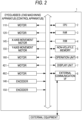
- the eyeglasses lens machining apparatus 1 includes a CPU (processor) 2 that controls the eyeglasses lens machining apparatus 1.
- a RAM 3, a ROM 4, a non-volatile memory 5, an operation unit 6, a display unit (display) 7, and an external communication I/F 8 are connected to the CPU 2 via a bus.
- various devices such as the motors described above (the motor 110, the motor 120, the X-axis movement motor 145, the Y-axis movement motor 150, the motor 160, the motor 421, the motor 482, the encoder 146, and the encoder 158) are connected to the CPU 2 via the bus.
- the RAM 3 temporarily stores various types of information.
- Various programs, initial values, and the like are stored in the ROM 4.
- the non-volatile memory 5 is a non-transitory storage medium (for example, flash ROM, hard disk drive, or the like) which can hold storage contents even when the supply of power is interrupted.
- the non-volatile memory 5 may store a control program (for example, a state management program, or the like) for controlling the operation of the eyeglasses lens machining apparatus (control apparatus) 1.
- the operation unit 6 accepts an input of various instructions from an operator. For example, a touch panel provided on a surface of the display unit 7, an operation button, or the like may be used as the operation unit 6.
- the display unit 7 can display various images such as characters such as operation guidance, identifiers (for example, QR code (registered trademark) or the like), a shape of the lens LE, a shape of a frame, and the like.
- the external communication I/F 8 connects the eyeglasses lens machining apparatus 1 to external equipment.
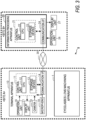
- the eyeglasses lens machining system 9 of the present embodiment includes the eyeglasses lens machining apparatus 1 (see FIGS. 1 and 2 ), a terminal apparatus 10, and an information processing apparatus 20.
- the terminal apparatus 10 is used at a site (site A in the present embodiment) at which the eyeglasses lens machining apparatus 1 is installed.
- the information processing apparatus 20 is disposed at a site (site B in the present embodiment) different from the site at which the eyeglasses lens machining apparatus 1 is installed.
- the information processing apparatus 20 can acquire information on the eyeglasses lens machining apparatus 1, and process the acquired information.
- the information on the eyeglasses lens machining apparatus 1 is transmitted to the information processing apparatus 20 via the terminal apparatus 10. Therefore, even in a case where the eyeglasses lens machining apparatus 1 is not connected to a network and the eyeglasses lens machining apparatus 1 and the information processing apparatus 20 are disposed at different sites, the information processing apparatus 20 can appropriately acquire information on the eyeglasses lens machining apparatus 1. Meanwhile, in a case or the like where the eyeglasses lens machining apparatus 1 is connected to a network, the terminal apparatus 10 can be omitted.
- the terminal apparatus 10 is used by a user at the site A at which the eyeglasses lens machining apparatus 1 is installed.
- the user of the terminal apparatus 10 may be, for example, an agent operator entrusted with a part of a task of a manufacturer of the eyeglasses lens machining apparatus 1, a user himself or herself using the eyeglasses lens machining apparatus 1, or the like.
- the terminal apparatus 10 of the present embodiment is a mobile terminal such as a smart phone or a tablet terminal. Meanwhile, a device other than the mobile terminal (for example, a PC or the like) may be used as the terminal apparatus 10.
- the terminal apparatus 10 includes a control unit 11 that performs various types of control processing, and a communication I/F 14.
- the control unit 11 includes a CPU 12 which is a controller that performs control, and a storage device 13 which can store programs, data, and the like.
- the communication I/F 14 connects the terminal apparatus 10 with external equipment (for example, the information processing apparatus 20) via a network 30 (for example, the Internet).
- the terminal apparatus 10 includes an operation unit 16, a display unit (monitor) 17, a camera (photographing unit) 18, and a microphone (sound input unit) 19.
- the operation unit 16 is operated by a user in order for the user to input various instructions to the terminal apparatus 10.
- the display unit 17 displays various images.
- the camera 18 captures various images. Although the details will be described below, the camera 18 of the present embodiment is also used as an identifier reader for reading an identifier.
- the microphone 19 inputs various sounds, and outputs signals corresponding to the sounds to the control unit 11.
- At least one of the operation unit 16, the display unit 17, the camera 18, and the microphone 19 may be external equipment that is not built into the terminal apparatus 10.
- a PC for example, a PC, a server, or the like can be used as the information processing apparatus 20.
- the PC is used for the information processing apparatus 20 of the present embodiment.
- the information processing apparatus 20 may be, for example, a server of a manufacturer that provides a cloud service (a so-called cloud server), or a server other than the cloud server (for example, a server of a manufacturer that manufactures the eyeglasses lens machining apparatus 1, and the like).
- the information processing apparatus 20 includes a control unit 21 that performs various types of control processing and a communication I/F 24.
- the control unit 21 includes a CPU 22 which is a controller that performs control, and a storage device 23 that can store programs, data, and the like.
- the communication I/F 24 connects the information processing apparatus 20 with external equipment (for example, the terminal apparatus 10 or the like) via the network 30.
- the information processing apparatus 20 is connected to an operation unit 26 and a display unit 27.
- Operation check control processing executed by the control apparatus that controls the eyeglasses lens machining apparatus 1 will be described with reference to FIGS. 4 to 6 .
- the operation check control processing illustrated in the present embodiment is executed by the CPU 2 of the eyeglasses lens machining apparatus (control apparatus) 1 according to a state management program stored in the non-volatile memory 5.
- a check operation is an operation to be executed by the eyeglasses lens machining apparatus 1 to check a state of the eyeglasses lens machining apparatus 1 with as high accuracy as possible.
- the check operation according to the present embodiment is executed by the eyeglasses lens machining apparatus 1 to check a cause of an operation defect that has a possibility of occurring in the eyeglasses lens machining apparatus 1. More specifically, the check operation according to the present embodiment is an operation (that is, a dedicated operation for state check) executed separately from an operation (for example, at least one of a machining operation, a measurement operation, a communication operation, and the like) of the eyeglasses lens machining apparatus 1, which is actually necessary to be executed to fit the lens LE into an eyeglasses frame.
- some of a plurality of check operations include an operation of driving a plurality of motors 110, 120, 145, 150, 160, 421, and 482 in a state in which the lens LE is not held by the lens holding portion 100. Therefore, the cause of the operation defect is estimated more appropriately.
- the CPU 2 determines whether an operation defect is detected in the eyeglasses lens machining apparatus 1 (that is, whether an error occurs) (S10).
- the CPU 2 can detect the operation defect that occurs in the apparatus, based on, for example, signals from various actuators, sensors, and the like.
- the CPU 2 acquires operation defect information (for example, an error code or the like) indicating a content of the detected operation defect (S11).
- the CPU 2 notifies a user of the fact that the operation defect (error) occurs, and inquires of the user whether to cause the eyeglasses lens machining apparatus 1 to execute a check operation.
- the CPU 2 causes the display unit 7 to display an operation defect detection inquiry screen 50 (S12).
- an operation defect detection inquiry screen 50 As illustrated in FIG. 5 , a message for notifying the user that the operation defect (error) occurs, and an error code indicating the content of the operation defect are displayed on the operation defect detection inquiry screen 50. Further, a message for inquiring of the user whether to execute the check operation (in some cases, referred to as a "self-check") and "YES" and “NO” buttons are displayed on the operation defect detection inquiry screen 50.
- the user operates the "YES” button in a case of executing the check operation, and the "NO” button in a case of not executing the check operation.
- the error notification method and the like can be selected as appropriate. For example, the notification of the error may be given by a sound.
- the processing transitions to S15.
- the CPU 2 selects the check operation for checking a cause of the detected operation defect as the check operation to be actually executed. Specifically, the CPU 2 selects one or a plurality of check operations associated with the operation defect information (that is, the content of the operation defect detected in S10) acquired in S11 among the plurality of check operations that can be executed in the eyeglasses lens machining apparatus 1, as the check operation to be actually executed (S14). Therefore, the check operation to be executed by the eyeglasses lens machining apparatus 1 is automatically selected according to the content of the detected operation defect.
- the CPU 2 determines whether the operation defect information is input by the user (S15). In the present embodiment, for example, in a case where a defect occurs in the machining of the lens LE executed by the eyeglasses lens machining apparatus 1, the user can input operation defect information related to the defect of the machining that occurs to the eyeglasses lens machining apparatus 1 via the operation unit 6 or the like, and then execute an appropriate check operation. In a case where the operation defect information is input (YES in S15), the CPU 2 acquires the input operation defect information (S16). The CPU 2 selects the check operation for checking the cause of the operation defect indicated by the input operation defect information as the check operation to be actually executed. Specifically, the CPU 2 selects one or a plurality of check operations associated with the input operation defect information, among the plurality of check operations that can be executed in the eyeglasses lens machining apparatus 1, as the check operation to be actually executed (S17).
- the check operation to be executed is associated in advance with a type of each of the operation defect information.
- data table data
- each of a plurality of operation defect information is associated with the content of the check operation to be executed by the eyeglasses lens machining apparatus is stored in a database in advance.
- the CPU 2 selects a check operation associated with the acquired operation defect information in the table data as the check operation to be actually executed.
- the association of the type of each of the operation defect information with the check operation to be executed is appropriately updated by an operator of a manufacturer or the like, according to an analysis result of the cause of the occurrence of the operation defect. Therefore, it is easy to execute an appropriate check operation according to the content of the operation defect that occurs.
- FIG. 6 is an enlarged perspective view of an edge portion 60 of the machined lens L.
- a bevel 61 is formed for fitting the lens LE to an eyeglasses frame.
- a foot portion 62 is formed between a base portion of the bevel 61 and front and back lens surfaces of the lens LE.
- a chamfer portion 63 is formed on each of a front side rib portion and a back side rib portion of the lens LE.
- a groove portion also may be formed instead of the bevel 61.
- a cause of a defect that occurs in a shape of the edge portion 60 including at least one of the bevel 61, the foot portion 62, the chamfer portion 63, and the groove portion a case where the defect occurs in a relative movement of the lens LE and the machining tool in the X-axis direction, a case where the defect occurs in the measurement of the thickness of the lens LE, and the like are considered.
- a position of the bevel 61 formed on the lens LE may be deviated in the X-axis direction.
- the position of the bevel 61 formed on the edge portion 60 has a possibility of being deviated.
- the CPU 2 includes check operations for the X-axis movement motor 145 and the lens shape measurement unit (lens thickness measurement unit) 200 in the check operation to be actually executed. As a result, it is easier to more appropriately estimate the cause of the operation defect related to the machining of the edge portion 60.
- the CPU 2 determines whether an instruction to execute all check operations among the plurality of check operations that can be executed by the eyeglasses lens machining apparatus 1 is input (S18). For example, in a case where maintenance of the eyeglasses lens machining apparatus 1 is executed, the user can input the instruction to execute all the check operations via the operation unit 6 or the like. In a case where the instruction is not input (NO in S18), the processing returns to S10. In a case where the instruction to execute all the check operations is input (YES in S18), the CPU 2 selects all the plurality of check operations that can be executed in the eyeglasses lens machining apparatus 1 as the check operation to be actually executed (S19).
- the selected check operation is executed (S21 to S23). Specifically, in a case where at least one of the plurality of motors 110, 120, 145, 150, 160, 421, and 482 is selected as a target of the check operation, a movement amount check operation is executed on the target motor (S21). In the movement amount check operation, an instruction to move the target object by a predetermined amount is given to the target motor.
- the target object to be moved may be an object other than the lens LE (for example, the carriage, the shaft, or the like).
- the movement includes linear movement as well as rotational movement or the like.
- a datum movement check operation is executed on the target motor (S22).
- the target object is repeatedly moved to a datum position by the motor selected as the target.
- the target object to be moved may be an object other than the lens LE.
- a type of movement may be rotational movement or the like instead of linear movement.
- the datum movement check operation (S22) is executed, in the processing in S24 described below, information indicating a detection result of the datum position by the datum sensor is output as result information related to the check operation. As a result, it is facilitated to appropriately resolve the defect of the datum detection that is likely to occur due to the machining waste or the like.
- the CPU 2 executes a check operation other than the movement amount check operation and the datum movement check operation, among the selected check operations (S23).
- S23 for example, an operation of checking whether various signals are appropriately transmitted and received may be executed.
- the CPU 2 outputs the result information indicating the result of the executed check operation (S24). As a result, it becomes easier to execute appropriate measures on the eyeglasses lens machining apparatus 1, based on the result of the check operation.
- the CPU 2 outputs the result information by causing the display unit 7 to display an identifier (for example, a QR code (registered trademark) or the like) indicating the result information of the check operation.
- the identifier indicating the result information of the check operation is displayed on the display unit 7.
- the operator for example, the user of the eyeglasses lens machining apparatus 1, and the like
- the terminal apparatus 10 transmits the result information acquired by reading the identifier to the information processing apparatus 20 via the network 30 (S3). Therefore, in the present embodiment, even when the eyeglasses lens machining apparatus 1 is not connected to the network, the operation check result information is appropriately transmitted to the information processing apparatus 20.
- the CPU 22 of the information processing apparatus 20 analyzes the acquired result information by using an analysis tool constructed in advance (S4).
- the analysis tool is constructed in advance, based on the analysis results of the operation defects that have occurred in the past in the eyeglasses lens machining apparatus. Therefore, even in a case where a skilled person who is good at analyzing result information cannot be involved in the work, the result information can be appropriately analyzed by the analysis tool.
- spreadsheet software in which algorithms and standards for analyzing result information are defined is used as the analysis tool.
- the algorithms and standards are defined based on the experience of result information analysis by an operator (including skilled persons) in the past.
- the algorithms and standards will also be updated based on new analysis results. Therefore, the result information is analyzed with higher accuracy.
- a tool other than the spreadsheet software for example, a mathematical model pre-trained by a machine learning algorithm to output analysis results by inputting result information
- a content of the measures to be executed is presented to the eyeglasses lens machining apparatus 1 (S5).
- the content of the measures to be executed may be determined by the information processing apparatus 20, or may be determined by an operator or the like who grasps the analysis result. Further, the content of the measures to be executed may be presented to the terminal apparatus 10 by e-mail or the like, or may be presented to the user of the eyeglasses lens machining apparatus 1 by telephone or the like.
- the techniques disclosed in the embodiments described above are merely examples. Therefore, the techniques described in the embodiment described above can be modified. For example, only a part of the technique described in the embodiments described above can be executed. Specifically, the processing (S4) of analyzing the result information of the operation check using the analysis tool may be omitted. In this case, the result information of the operation check may be analyzed by the operator or the like. It is also possible for a device other than the information processing apparatus 20 (for example, the eyeglasses lens machining apparatus 1 or the terminal apparatus 10, and the like) to execute the analysis processing by the analysis tool. The result information of the check operation may be output by being displayed on a display unit (for example, the display unit 7 of the eyeglasses lens machining apparatus 1, and the like).
- a display unit for example, the display unit 7 of the eyeglasses lens machining apparatus 1, and the like.
- the processing of executing the check operation in S14, S17, S19, and S21 to S23 in FIG. 4 is an example of a "check operation execution step".
- the processing of outputting the check operation result information in S24 of FIG. 4 is an example of a "result output step”.
- the processing of acquiring the operation defect information in S11 and S16 in FIG. 4 is an example of an "operation defect information acquisition step”.
- the processing of analyzing the result information in SS4 in FIG. 7 is an example of an "analysis step".
Landscapes
- Engineering & Computer Science (AREA)
- Mechanical Engineering (AREA)
- Chemical & Material Sciences (AREA)
- Ceramic Engineering (AREA)
- Inorganic Chemistry (AREA)
- Manufacturing & Machinery (AREA)
- Physics & Mathematics (AREA)
- General Physics & Mathematics (AREA)
- Automation & Control Theory (AREA)
- Human Computer Interaction (AREA)
- General Engineering & Computer Science (AREA)
- Quality & Reliability (AREA)
- Eyeglasses (AREA)
- Grinding And Polishing Of Tertiary Curved Surfaces And Surfaces With Complex Shapes (AREA)
Abstract
Description
- The present disclosure relates to a state management program and a state management method for managing a state of an eyeglasses lens machining apparatus.
- An eyeglasses lens machining apparatus that performs machining on an eyeglasses lens is widely used in an eyeglasses lens shop and the like. For example, an eyeglasses lens machining apparatus described in
Patent Literature 1 holds an eyeglasses lens by attaching a lens holding shaft to a cup attached to the eyeglasses lens. The eyeglasses lens machining apparatus can perform machining a peripheral edge of the held eyeglasses lens with a peripheral edge machining tool. Further, the eyeglasses lens machining apparatus described inPatent Literature 1 can form a hole at the held eyeglasses lens with a drilling tool. - Patent Literature 1:
JP2018-004930A - In a case where an operation defect occurs in the eyeglasses lens machining apparatus, it is desirable to execute appropriate measures (for example, repair, replacement of components, change of settings, and the like) according to a content of the operation defect on the eyeglasses lens machining apparatus. Here, even when the contents of the operation defects that occur are the same, causes of the operation defects are different from each other, in many cases. A skilled person who is familiar with management of the eyeglasses lens machining apparatus can reduce the man-hours and a time when the measures are actually performed, for example, by inquiring about a situation of the apparatus in advance, checking information indicating an operation of the apparatus in advance, or the like. Meanwhile, in the current situation, when the skilled person cannot be involved, there is a high frequency with which appropriate measures are not performed on the eyeglasses lens machining apparatus.
- A typical object of the present disclosure is to provide a state management program and a state management method capable of appropriately managing a state of an eyeglasses lens machining apparatus.
- According to a typical embodiment in the present disclosure, there is provided a state management program executed by a control apparatus that controls an eyeglasses lens machining apparatus in order to manage a state of the eyeglasses lens machining apparatus, the state management program causing the control apparatus, by causing a control unit of the control apparatus to execute the state management program, to perform: a check operation execution step of causing the eyeglasses lens machining apparatus to execute a check operation for checking a state of the eyeglasses lens machining apparatus; and a result output step of outputting information indicating a result of the executed check operation.
- According to a first aspect of the typical embodiment in the present disclosure, there is provided a state management method performed by a control apparatus that controls an eyeglasses lens machining apparatus in order to manage a state of the eyeglasses lens machining apparatus, the state management method including: a check operation execution step of causing the eyeglasses lens machining apparatus to execute a check operation for checking a state of the eyeglasses lens machining apparatus; and a result output step of outputting information indicating a result of the executed check operation.
- According to a second aspect of the typical embodiment in the present disclosure, there is provided a state management method of an eyeglasses lens machining apparatus, which is performed in an eyeglasses lens machining system including the eyeglasses lens machining apparatus that machines an eyeglasses lens and an information processing apparatus that enables to acquire information related to the eyeglasses lens machining apparatus, the state management method including: a check operation execution step in which the eyeglasses lens machining apparatus executes a check operation for checking a state; a result output step in which the eyeglasses lens machining apparatus outputs result information indicating a result of the executed check operation; and an analysis step in which the information processing apparatus acquires the result information output in the result output step, and analyzes the acquired result information by using an analysis tool constructed in advance.
- According to the state management program and the state management method of the present disclosure, a state of the eyeglasses lens machining apparatus is appropriately managed.
- The state management program described in the present disclosure is executed by the control apparatus that controls the eyeglasses lens machining apparatus to manage the state of the eyeglasses lens machining apparatus. The control unit of the control apparatus performs the check operation execution step and the result output step. In the check operation execution step, the control unit causes the eyeglasses lens machining apparatus to execute the check operation for checking the state of the eyeglasses lens machining apparatus. In the result output step, the control unit outputs the information indicating the result of the executed check operation.
- With the state management program described in the present disclosure, unlike a case where only an error output or the like is performed, the check operation for checking the state of the eyeglasses lens machining apparatus is executed by the eyeglasses lens machining apparatus, and the information indicating the result of the check operation is output. Therefore, it becomes easy to estimate the state of the eyeglasses lens machining apparatus (for example, a cause of operation defect or the like) based on the result of the check operation. Therefore, it becomes easier to perform appropriate processing on the eyeglasses lens machining apparatus.
- The check operation in the present disclosure is an operation executed to check the state of the eyeglasses lens machining apparatus with as high accuracy as possible. For example, in some cases, the check operation is executed by the eyeglasses lens machining apparatus to check the cause of the operation defect that has a possibility of occurring in the eyeglasses lens machining apparatus in more detail. The check operation may be an operation (that is, a dedicated operation for state check) executed separately from the operation (for example, at least one of a machining operation, a measurement operation, a communication operation, and the like) that is actually necessary to be executed to fit the eyeglasses lens into a frame. In this case, the cause of the operation defect is estimated more appropriately. Meanwhile, at least a part of the check operation may include an operation actually performed to fit the eyeglasses lens in the frame (for example, a machining operation executed on the eyeglasses lens, and the like).
- The control apparatus that controls the operation of the eyeglasses lens machining apparatus may be the eyeglasses lens machining apparatus itself, or may be another device (for example, a PC or the like) connected to the eyeglasses lens machining apparatus. That is, the device that executes the eyeglasses lens machining control program according to the present disclosure is not limited to the eyeglasses lens machining apparatus. In addition, the control units of a plurality of devices may cooperate to execute the eyeglasses lens machining control program.
- The control unit may further execute an operation defect information acquisition step. In the operation defect information acquisition step, operation defect information indicating a content of an operation defect in the eyeglasses lens machining apparatus is acquired. In the operation check execution step, a check operation for checking a cause of the operation defect indicated by the acquired operation defect information may be executed. In this case, the cause of the operation defect of the eyeglasses lens machining apparatus (for example, an operation defect that actually occurs in the eyeglasses lens machining apparatus, an operation defect that has a possibility of occurring in the eyeglasses lens machining apparatus, or the like) is appropriately checked based on the result of the check operation.
- In the check operation execution step, among a plurality of the check operations, one or a plurality of check operations associated with the acquired operation defect information (that is, corresponding to the content (type) of the operation defect indicated by the operation defect information) may be executed by the eyeglasses lens machining apparatus. In this case, unlike a case or the like where only an output of an error is simply executed, the check operation corresponding to the content of the operation defect is executed by the eyeglasses lens machining apparatus, and the information indicating the result of the check operation is output. Therefore, it is easier to estimate the cause of the operation defect based on the result of the check operation. Therefore, it becomes easier to perform appropriate processing on the eyeglasses lens machining apparatus. In addition, since a check operation is performed according to the content of the operation defect (for example, check operation for a portion highly related to actual operation defects) among the plurality of check operations, the cause of the operation defect can be estimated more efficiently as compared with a case where all the check operations are always performed.
- A method of associating the operation defect information (for example, the content of the operation defect indicated by the operation defect information) with the check operation to be executed by the eyeglasses lens machining apparatus can be appropriately selected. For example, data (for example, table data or the like) in which each of a plurality of operation defect information is associated with the content of the check operation to be executed by the eyeglasses lens machining apparatus may be stored in a storage device such as a database in advance. The control unit may refer to the data stored in the storage device to select a check operation associated with the acquired operation defect information as the check operation to be executed by the eyeglasses lens machining apparatus. Further, a program may be constructed in advance such that processing of selecting a predetermined check operation for each operation defect information is performed.
- In a case where the eyeglasses lens machining apparatus detects an operation defect that occurs in the apparatus, in the operation defect information acquisition step, the control unit may acquire operation defect information indicating a content of the detected operation defect. In this case, the content of the check operation to be executed by the eyeglasses lens machining apparatus is automatically selected according to the content of the operation defect detected by the eyeglasses lens machining apparatus. Therefore, the cause of the detected operation defect is estimated more appropriately.
- In the operation defect information acquisition step, the control unit may acquire operation defect information input by a user. In this case, for example, even in a case where the operation defect is not detected by the eyeglasses lens machining apparatus, the user can check workmanship or the like of the actually machined eyeglasses lens in person to cause the eyeglasses lens machining apparatus to appropriately execute the check operation for checking the cause of the operation defect that occurs.
- In this manner, the operation defect information may include at least one of information indicating the content of the operation defect detected by the eyeglasses lens machining apparatus itself and the operation defect information input by the user.
- In a case where a content of an operation defect indicated by the operation defect information is an operation defect related to machining on an edge shape of the eyeglasses lens (for example, an operation defect causing a deviation in at least one of a shape, a position, and a size of a formed edge portion), the check operation may include a check operation on an X-axis movement motor and a lens pressure measurement unit. The X-axis movement motor moves the eyeglasses lens in a direction along lens holding shafts (referred to as "lens chuck shafts" in some cases) that hold the eyeglasses lens by interposing the eyeglasses lens between the lens holding shafts. The lens thickness measurement unit measures a thickness of the eyeglasses lens. As the cause of the operation defect related to the machining on the edge shape, a case where a defect occurs in movement in the direction along the lens holding shaft (that is, in the thickness direction of the lens), a case where a defect occurs in measuring the thickness of the lens, a case where both defects occur, and the like are conceivable. Therefore, when checking the cause of the operation defect related to machining on the edge shape, the cause of the operation defect can be estimated more appropriately by performing the check operation on the X-axis movement motor and the lens thickness measurement unit. The edge shape of the machined eyeglasses lens includes at least one shape such as a bevel, a groove, a foot portion, and a chamfer portion in the edge portion of the lens.
- Meanwhile, a specific method for causing the eyeglasses lens machining apparatus to execute the check operation can be selected as appropriate. For example, in the check operation execution step, all of the plurality of check operations may be performed. In this case, the states of many portions in the eyeglasses lens machining apparatus are appropriately estimated based on the result of the check operation. The control unit may execute all of the plurality of check operations, for example, when regular maintenance is performed on the eyeglasses lens machining apparatus. Further, the control unit may execute all of the plurality of check operations when a certain operation defect occurs in the eyeglasses lens machining apparatus.
- The check operation executed in the check operation execution step may include a movement amount check operation of performing an instruction for causing at least one motor provided in the eyeglasses lens machining apparatus to move a target object by a predetermined amount. In a case where the movement amount check operation is executed, information indicating a relationship between a movement amount instructed to the motor and a movement amount of the target object actually moved may be output in the result output step. In this case, it is easier to appropriately determine whether the cause of the operation defect is a defect related to the movement amount of the target object by the motor, based on the result of the operation check. Therefore, it becomes easier to perform appropriate processing on the eyeglasses lens machining apparatus.
- The check operation executed in the check operation execution step may include a datum movement check operation of causing at least one motor provided in the eyeglasses lens machining apparatus to move the target object to a datum position. In a case where the datum movement check operation is executed, information indicating a detection result of a datum position may be output in the result output step. In this case, it is easier to appropriately determine whether the cause of the operation defect is a defect related to the detection of the motor at the datum position, based on the result of the operation check. Therefore, it becomes easier to perform appropriate processing on the eyeglasses lens machining apparatus. In particular, in a case where a photo sensor or the like is used as a datum sensor in the eyeglasses lens machining apparatus, light of the photo sensor is blocked by machining waste or the like and a defect occurs in the datum detection, in many cases. On the other hand, by causing the eyeglasses lens machining apparatus to execute the datum movement check operation, it becomes easier to appropriately resolve the defect in the datum detection that is likely to occur due to machining waste or the like.
- A specific method for executing the datum movement check operation can be selected as appropriate. For example, the control unit may acquire the detection result of the datum position each time the target object is repeatedly moved to the datum position a plurality of times. In this case, the cause of the operation defect can be more accurately estimated depending on whether the datum is accurately detected each time movement to the datum position is performed the plurality of times.
- In the result output step, the control unit may output result information of the check operation by causing the display unit to display an identifier indicating the result information. In this case, the operator (for example, the user of the eyeglasses lens machining apparatus, or the like) can appropriately process the result information by causing an identifier reader provided in a terminal apparatus or the like to read the identifier displayed on the display unit. For example, the operator can operate the terminal apparatus or the like to transmit the result information to another device (for example, an information processing apparatus or the like managed by a manufacturer of the eyeglasses lens machining apparatus). Therefore, even when the eyeglasses lens machining apparatus and the control apparatus are not connected to a network, the result information can be appropriately transmitted via the network. It is also possible to analyze the result information by using a device (for example, a terminal apparatus or the like) different from the control apparatus.
- Meanwhile, it is also possible to change the output method of the result information of the check operation. For example, the control apparatus (which may be the eyeglasses lens machining apparatus) may output the result information by transmitting the result information to another device via the Internet, NFC, Wi-Fi, Bluetooth (registered trademark), wired communication, or the like. Further, the control apparatus may output the result information by causing the display unit to display the result information of the check operation.
- In addition, a form of the output result information can be selected as appropriate. For example, a parameter, a graph, image data (for example, a still image, a moving image, or the like obtained by imaging at least a part of motor operation), and sound data (for example, motor sound or the like) indicating the result of the check operation may be output as the result information.
- The technique described in the present disclosure can also be expressed in aspects other than an information management program (for example, state management method, state management apparatus, eyeglasses lens machining apparatus, eyeglasses lens machining system, state management system, and the like).
- The eyeglasses lens machining system described in the present disclosure includes the eyeglasses lens machining apparatus that performs machining on the eyeglasses lens, and the information processing apparatus that enables to acquire information on the eyeglasses lens machining apparatus. The eyeglasses lens machining system performs the check operation execution step, the result output step, and the analysis step. In the check operation execution step, the eyeglasses lens machining apparatus executes a check operation for checking a state. In the result output step, the eyeglasses lens machining apparatus outputs result information indicating a result of the executed check operation. In the analysis step, the information processing apparatus acquires the result information output in the result output step, and analyzes the acquired result information by using an analysis tool constructed in advance.
- In this case, after the check operation for checking the state of the eyeglasses lens machining apparatus is executed by the eyeglasses lens machining apparatus, the result information indicating the result of the check operation is analyzed by the information processing apparatus that is a device different from the eyeglasses lens machining apparatus. Therefore, even when the analysis tool is not mounted in each eyeglasses lens machining apparatus (or the control apparatus connected to the eyeglasses lens machining apparatus), the result information of the check operation can be appropriately analyzed by the analysis tool.
- Meanwhile, it is also possible to change the method of analysis using the analysis tool. For example, the analysis tool may be mounted on the eyeglasses lens machining apparatus or the control apparatus connected to the eyeglasses lens machining apparatus. In this case, the result of the check operation is appropriately analyzed on each eyeglasses lens machining apparatus side.
- A specific aspect of the analysis tool can also be selected as appropriate. For example, spreadsheet software, an application, or the like, in which algorithms, standards, or the like for analyzing the result information are defined, may be used as the analysis tool. Further, a mathematical model pre-trained by machine learning algorithms may also be used as the analysis tool to output an analysis result by inputting the result information.
-
-
FIG. 1 is a schematic configuration diagram of a machining mechanism of an eyeglasseslens machining apparatus 1. -
FIG. 2 is a block diagram illustrating an electric configuration of the eyeglasseslens machining apparatus 1. -
FIG. 3 is a block diagram illustrating a system configuration of an eyeglasses lens machining system 9. -
FIG. 4 is a flowchart of check operation control processing which is executed by the eyeglasseslens machining apparatus 1. -
FIG. 5 is a diagram illustrating an example of an inquiry screen forerror occurrence time 50. -
FIG. 6 is a perspective view illustrating an example of anedge portion 60 of a machined lens LE. -
FIG. 7 is a sequence diagram illustrating an example of a flow of processing executed by the eyeglasses lens machining system 9. - Hereinafter, one of the typical embodiments in the present disclosure will be described with reference to the drawings. First, an eyeglasses
lens machining apparatus 1 of the present embodiment will be described. The eyeglasseslens machining apparatus 1 performs machining on an eyeglasses lens LE. The eyeglasseslens machining apparatus 1 according to the present embodiment also serves as a control apparatus that controls various operations and processing, such as a machining operation. Meanwhile, a control apparatus (for example, a personal computer or the like) that controls the eyeglasseslens machining apparatus 1 may be used separately from the eyeglasseslens machining apparatus 1. - As illustrated in
FIG. 1 , the eyeglasseslens machining apparatus 1 of the present embodiment includes alens holding portion 100, a lensshape measurement unit 200, a firstmachining tool unit 300, and a secondmachining tool unit 400. Thelens holding portion 100 includes lens holding shafts (lens chuck shafts) 102R and 102L for holding the lens LE by interposing the lens LE between thelens holding shafts lens holding portion 100 includes alens rotation unit 100a, a holdingshaft moving unit 100b, and an inter-shaftdistance changing unit 100c. - The
lens rotation unit 100a rotates a pair oflens holding shafts shaft moving unit 100b moves thelens holding shafts distance changing unit 100c moves thelens holding shafts machining tool unit 300 and the second machining tool unit 400 (this is defined as a Y-direction). Further, the inter-shaftdistance changing unit 100c changes a distance between the lensshape measurement unit 200 and thelens holding shafts - Hereinafter, a specific example of each configuration in the eyeglasses
lens machining apparatus 1 will be described in detail. Thelens holding portion 100 is mounted on abase 170 of a main body of the eyeglasseslens machining apparatus 1. - The
lens rotation unit 100a will be described. Thelens holding shaft 102R is held by aright arm 101R of acarriage 101 of thelens holding portion 100 and thelens holding shaft 102L is held by aleft arm 101L of thecarriage 101 of thelens holding portion 100 to be respectively rotatable and coaxial with each other. When thelens holding shaft 102R is moved toward thelens holding shaft 102L side by amotor 110 attached to theright arm 101R, the lens LE is interposed and held between the twolens holding shafts lens holding shafts motor 120 attached to theright arm 101R. - The holding
shaft moving unit 100b will be described. An X-axismovement support base 140 is provided atshafts lens holding shafts grindstone rotation shaft 161a. The X-axismovement support base 140 can be moved in the X-axis direction along theshafts X-axis movement motor 145. Thecarriage 101 is mounted on the X-axismovement support base 140. An encoder 146 (seeFIG. 2 ) is provided on a rotation shaft of theX-axis movement motor 145. In the present embodiment, X-direction positions of thelens holding shafts encoder 146 are used to measure shapes of a front surface and a rear surface of the lens LE. - The inter-shaft
distance changing unit 100c will be described. Ashaft 156 extending in a direction connecting thelens holding shafts grindstone rotation shaft 161a is fixed to the X-axismovement support base 140. In a case where a Y-axis movement motor 150 is rotated, aball screw 155 extending in the Y-direction is rotated. As a result, thecarriage 101 is moved along theshaft 156 in the Y-axis direction. Anencoder 158 that detects a position of thecarriage 101 in the Y-direction is provided on a rotation shaft of the Y-axis movement motor 150. - The lens
shape measurement unit 200 will be described. The lensshape measurement unit 200 of the present embodiment is fixed to the base 170 at a position opposite to the firstmachining tool unit 300 via thecarriage 101. The lensshape measurement unit 200 includes a lens edgeposition measurement unit 200F and a lens edgeposition measurement unit 200R. The lens edgeposition measurement unit 200F has a tracing stylus that contacts a front surface of the lens LE. The lens edgeposition measurement unit 200R has a tracing stylus that contacts a rear surface of the lens LE. When thecarriage 101 is moved in the Y-axis direction based on target lens shape data, and thelens holding shafts position measurement units shape measurement unit 200 functions as a lens thickness measurement unit that measures a thickness of the lens LE. For the configuration of the lens edgeposition measurement units JP2003-145328A - The first
machining tool unit 300 will be described. The firstmachining tool unit 300 includes a peripheraledge machining tool 168 which is one of lens machining tools. The peripheraledge machining tool 168 of the present embodiment includes arough grindstone 162 for glass, a finishinggrindstone 164 having a V-groove (beveling groove) for forming a bevel on a lens and a flat machining surface, a flatmirror finishing grindstone 165, a high curvelens finishing grindstone 166, arough grindstone 167 for plastics, and the like. A plurality of grindstones of the peripheraledge machining tool 168 are coaxially attached to the grindstone rotation shaft (grindstone spindle) 161a. Thegrindstone rotation shaft 161 a is rotated by themotor 160. A peripheral edge of the lens LE held by thelens holding shafts edge machining tool 168. - The second
machining tool unit 400 will be described. The secondmachining tool unit 400 includes a finishing tool, a drilling tool, amotor 421, amotor 482, and the like. The finishing tool is rotated around a rotation axis to perform finishing on the peripheral edge of the lens LE (for example, at least one of grooving, beveling, step forming, and the like). The drilling tool forms a hole in the lens LE. The drilling tool of the present embodiment forms a hole extending in an axial direction in the lens LE by being moved in the axial direction while being rotated around the rotation axis. Themotor 421 rotates the finishing tool and the drilling tool. Themotor 482 pivots the finishing tool and the drilling tool. - With reference to
FIG. 2 , an electrical configuration of the eyeglasses lens machining apparatus (also serving as a control apparatus) 1 will be described. The eyeglasseslens machining apparatus 1 includes a CPU (processor) 2 that controls the eyeglasseslens machining apparatus 1. ARAM 3, aROM 4, anon-volatile memory 5, anoperation unit 6, a display unit (display) 7, and an external communication I/F 8 are connected to theCPU 2 via a bus. Further, various devices such as the motors described above (themotor 110, themotor 120, theX-axis movement motor 145, the Y-axis movement motor 150, themotor 160, themotor 421, themotor 482, theencoder 146, and the encoder 158) are connected to theCPU 2 via the bus. - The
RAM 3 temporarily stores various types of information. Various programs, initial values, and the like are stored in theROM 4. Thenon-volatile memory 5 is a non-transitory storage medium (for example, flash ROM, hard disk drive, or the like) which can hold storage contents even when the supply of power is interrupted. Thenon-volatile memory 5 may store a control program (for example, a state management program, or the like) for controlling the operation of the eyeglasses lens machining apparatus (control apparatus) 1. Theoperation unit 6 accepts an input of various instructions from an operator. For example, a touch panel provided on a surface of thedisplay unit 7, an operation button, or the like may be used as theoperation unit 6. Thedisplay unit 7 can display various images such as characters such as operation guidance, identifiers (for example, QR code (registered trademark) or the like), a shape of the lens LE, a shape of a frame, and the like. The external communication I/F 8 connects the eyeglasseslens machining apparatus 1 to external equipment. - With reference to
FIG. 3 , a system configuration of an eyeglasses lens machining system 9 according to the present embodiment will be schematically described. The eyeglasses lens machining system 9 of the present embodiment includes the eyeglasses lens machining apparatus 1 (seeFIGS. 1 and2 ), aterminal apparatus 10, and aninformation processing apparatus 20. Theterminal apparatus 10 is used at a site (site A in the present embodiment) at which the eyeglasseslens machining apparatus 1 is installed. Theinformation processing apparatus 20 is disposed at a site (site B in the present embodiment) different from the site at which the eyeglasseslens machining apparatus 1 is installed. - The
information processing apparatus 20 can acquire information on the eyeglasseslens machining apparatus 1, and process the acquired information. In the present embodiment, the information on the eyeglasseslens machining apparatus 1 is transmitted to theinformation processing apparatus 20 via theterminal apparatus 10. Therefore, even in a case where the eyeglasseslens machining apparatus 1 is not connected to a network and the eyeglasseslens machining apparatus 1 and theinformation processing apparatus 20 are disposed at different sites, theinformation processing apparatus 20 can appropriately acquire information on the eyeglasseslens machining apparatus 1. Meanwhile, in a case or the like where the eyeglasseslens machining apparatus 1 is connected to a network, theterminal apparatus 10 can be omitted. - The
terminal apparatus 10 is used by a user at the site A at which the eyeglasseslens machining apparatus 1 is installed. The user of theterminal apparatus 10 may be, for example, an agent operator entrusted with a part of a task of a manufacturer of the eyeglasseslens machining apparatus 1, a user himself or herself using the eyeglasseslens machining apparatus 1, or the like. Theterminal apparatus 10 of the present embodiment is a mobile terminal such as a smart phone or a tablet terminal. Meanwhile, a device other than the mobile terminal (for example, a PC or the like) may be used as theterminal apparatus 10. - The
terminal apparatus 10 includes acontrol unit 11 that performs various types of control processing, and a communication I/F 14. Thecontrol unit 11 includes aCPU 12 which is a controller that performs control, and astorage device 13 which can store programs, data, and the like. The communication I/F 14 connects theterminal apparatus 10 with external equipment (for example, the information processing apparatus 20) via a network 30 (for example, the Internet). - The
terminal apparatus 10 includes anoperation unit 16, a display unit (monitor) 17, a camera (photographing unit) 18, and a microphone (sound input unit) 19. Theoperation unit 16 is operated by a user in order for the user to input various instructions to theterminal apparatus 10. For theoperation unit 16, at least one of, for example, a touch panel, a keyboard, a mouse, and the like can be used. The display unit 17 displays various images. Thecamera 18 captures various images. Although the details will be described below, thecamera 18 of the present embodiment is also used as an identifier reader for reading an identifier. Themicrophone 19 inputs various sounds, and outputs signals corresponding to the sounds to thecontrol unit 11. At least one of theoperation unit 16, the display unit 17, thecamera 18, and themicrophone 19 may be external equipment that is not built into theterminal apparatus 10. - For example, a PC, a server, or the like can be used as the
information processing apparatus 20. As an example, the PC is used for theinformation processing apparatus 20 of the present embodiment. In a case where the server is used as theinformation processing apparatus 20, theinformation processing apparatus 20 may be, for example, a server of a manufacturer that provides a cloud service (a so-called cloud server), or a server other than the cloud server (for example, a server of a manufacturer that manufactures the eyeglasseslens machining apparatus 1, and the like). - The
information processing apparatus 20 includes acontrol unit 21 that performs various types of control processing and a communication I/F 24. Thecontrol unit 21 includes aCPU 22 which is a controller that performs control, and astorage device 23 that can store programs, data, and the like. The communication I/F 24 connects theinformation processing apparatus 20 with external equipment (for example, theterminal apparatus 10 or the like) via thenetwork 30. In addition, theinformation processing apparatus 20 is connected to anoperation unit 26 and adisplay unit 27. - Operation check control processing executed by the control apparatus that controls the eyeglasses
lens machining apparatus 1 will be described with reference toFIGS. 4 to 6 . The operation check control processing illustrated in the present embodiment is executed by theCPU 2 of the eyeglasses lens machining apparatus (control apparatus) 1 according to a state management program stored in thenon-volatile memory 5. - A check operation is an operation to be executed by the eyeglasses
lens machining apparatus 1 to check a state of the eyeglasseslens machining apparatus 1 with as high accuracy as possible. The check operation according to the present embodiment is executed by the eyeglasseslens machining apparatus 1 to check a cause of an operation defect that has a possibility of occurring in the eyeglasseslens machining apparatus 1. More specifically, the check operation according to the present embodiment is an operation (that is, a dedicated operation for state check) executed separately from an operation (for example, at least one of a machining operation, a measurement operation, a communication operation, and the like) of the eyeglasseslens machining apparatus 1, which is actually necessary to be executed to fit the lens LE into an eyeglasses frame. Specifically, some of a plurality of check operations include an operation of driving a plurality ofmotors lens holding portion 100. Therefore, the cause of the operation defect is estimated more appropriately. - As illustrated in
FIG. 4 , theCPU 2 determines whether an operation defect is detected in the eyeglasses lens machining apparatus 1 (that is, whether an error occurs) (S10). TheCPU 2 can detect the operation defect that occurs in the apparatus, based on, for example, signals from various actuators, sensors, and the like. In a case where the operation defect is detected (YES in S10), theCPU 2 acquires operation defect information (for example, an error code or the like) indicating a content of the detected operation defect (S11). TheCPU 2 notifies a user of the fact that the operation defect (error) occurs, and inquires of the user whether to cause the eyeglasseslens machining apparatus 1 to execute a check operation. As an example, in the present embodiment, theCPU 2 causes thedisplay unit 7 to display an operation defect detection inquiry screen 50 (S12). As illustrated inFIG. 5 , a message for notifying the user that the operation defect (error) occurs, and an error code indicating the content of the operation defect are displayed on the operation defectdetection inquiry screen 50. Further, a message for inquiring of the user whether to execute the check operation (in some cases, referred to as a "self-check") and "YES" and "NO" buttons are displayed on the operation defectdetection inquiry screen 50. The user operates the "YES" button in a case of executing the check operation, and the "NO" button in a case of not executing the check operation. The error notification method and the like can be selected as appropriate. For example, the notification of the error may be given by a sound. - In a case where an instruction not to execute the check operation is input (NO in S13), the processing transitions to S15. In a case where an instruction to execute the check operation is input (YES in S13), the
CPU 2 selects the check operation for checking a cause of the detected operation defect as the check operation to be actually executed. Specifically, theCPU 2 selects one or a plurality of check operations associated with the operation defect information (that is, the content of the operation defect detected in S10) acquired in S11 among the plurality of check operations that can be executed in the eyeglasseslens machining apparatus 1, as the check operation to be actually executed (S14). Therefore, the check operation to be executed by the eyeglasseslens machining apparatus 1 is automatically selected according to the content of the detected operation defect. - In a case where the operation defect is not detected (NO in S10), the
CPU 2 determines whether the operation defect information is input by the user (S15). In the present embodiment, for example, in a case where a defect occurs in the machining of the lens LE executed by the eyeglasseslens machining apparatus 1, the user can input operation defect information related to the defect of the machining that occurs to the eyeglasseslens machining apparatus 1 via theoperation unit 6 or the like, and then execute an appropriate check operation. In a case where the operation defect information is input (YES in S15), theCPU 2 acquires the input operation defect information (S16). TheCPU 2 selects the check operation for checking the cause of the operation defect indicated by the input operation defect information as the check operation to be actually executed. Specifically, theCPU 2 selects one or a plurality of check operations associated with the input operation defect information, among the plurality of check operations that can be executed in the eyeglasseslens machining apparatus 1, as the check operation to be actually executed (S17). - The processing in S14 and S17 will be described in more detail. In the present embodiment, the check operation to be executed is associated in advance with a type of each of the operation defect information. Specifically, data (table data) in which each of a plurality of operation defect information is associated with the content of the check operation to be executed by the eyeglasses lens machining apparatus is stored in a database in advance. The
CPU 2 selects a check operation associated with the acquired operation defect information in the table data as the check operation to be actually executed. The association of the type of each of the operation defect information with the check operation to be executed is appropriately updated by an operator of a manufacturer or the like, according to an analysis result of the cause of the occurrence of the operation defect. Therefore, it is easy to execute an appropriate check operation according to the content of the operation defect that occurs. - A specific example of a method of selecting a check operation to be actually executed according to a content of operation defect information will be described with reference to
FIG. 6. FIG. 6 is an enlarged perspective view of anedge portion 60 of the machined lens L. In the example illustrated inFIG. 6 , abevel 61 is formed for fitting the lens LE to an eyeglasses frame. Afoot portion 62 is formed between a base portion of thebevel 61 and front and back lens surfaces of the lens LE. Further, achamfer portion 63 is formed on each of a front side rib portion and a back side rib portion of the lens LE. In some cases, a groove portion also may be formed instead of thebevel 61. - As a cause of a defect that occurs in a shape of the
edge portion 60 including at least one of thebevel 61, thefoot portion 62, thechamfer portion 63, and the groove portion, a case where the defect occurs in a relative movement of the lens LE and the machining tool in the X-axis direction, a case where the defect occurs in the measurement of the thickness of the lens LE, and the like are considered. For example, as illustrated inFIG. 6 , in a case where a defect occurs in movement in the X-axis direction, a position of thebevel 61 formed on the lens LE may be deviated in the X-axis direction. In addition, even in a case where the thickness of the lens LE is not accurately measured, the position of thebevel 61 formed on theedge portion 60 has a possibility of being deviated. - Therefore, in S14 and S17 in the present embodiment, in a case where the content of the operation defect information is an operation defect related to the machining of the
edge portion 60 of the lens LE (for example, the operation defect causing the defect of at least one of the shape, the position, and the size), theCPU 2 includes check operations for theX-axis movement motor 145 and the lens shape measurement unit (lens thickness measurement unit) 200 in the check operation to be actually executed. As a result, it is easier to more appropriately estimate the cause of the operation defect related to the machining of theedge portion 60. - With reference to
FIG. 4 , description will be continued. In a case where the operation defect information is not input by the user (NO in S15), theCPU 2 determines whether an instruction to execute all check operations among the plurality of check operations that can be executed by the eyeglasseslens machining apparatus 1 is input (S18). For example, in a case where maintenance of the eyeglasseslens machining apparatus 1 is executed, the user can input the instruction to execute all the check operations via theoperation unit 6 or the like. In a case where the instruction is not input (NO in S18), the processing returns to S10. In a case where the instruction to execute all the check operations is input (YES in S18), theCPU 2 selects all the plurality of check operations that can be executed in the eyeglasseslens machining apparatus 1 as the check operation to be actually executed (S19). - In a case where the check operation is selected in any of S14, S17, and S19, the selected check operation is executed (S21 to S23). Specifically, in a case where at least one of the plurality of
motors - In addition, in a case where at least one of the plurality of
motors - Next, the
CPU 2 executes a check operation other than the movement amount check operation and the datum movement check operation, among the selected check operations (S23). In S23, for example, an operation of checking whether various signals are appropriately transmitted and received may be executed. - Next, the
CPU 2 outputs the result information indicating the result of the executed check operation (S24). As a result, it becomes easier to execute appropriate measures on the eyeglasseslens machining apparatus 1, based on the result of the check operation. In the present embodiment, theCPU 2 outputs the result information by causing thedisplay unit 7 to display an identifier (for example, a QR code (registered trademark) or the like) indicating the result information of the check operation. - With reference to
FIG. 7 , a flow of state management processing of the eyeglasseslens machining apparatus 1 in the entire eyeglasses lens machining system 9 will be described. As described above, when the check operation is performed in the check operation control processing (S 1, seeFIG. 4 ) executed by the eyeglasseslens machining apparatus 1, the identifier indicating the result information of the check operation is displayed on thedisplay unit 7. Here, the operator (for example, the user of the eyeglasseslens machining apparatus 1, and the like) causes the identifier reader provided in theterminal apparatus 10 to read the identifier displayed on the display unit 7 (S2). Theterminal apparatus 10 transmits the result information acquired by reading the identifier to theinformation processing apparatus 20 via the network 30 (S3). Therefore, in the present embodiment, even when the eyeglasseslens machining apparatus 1 is not connected to the network, the operation check result information is appropriately transmitted to theinformation processing apparatus 20. - Next, the
CPU 22 of theinformation processing apparatus 20 analyzes the acquired result information by using an analysis tool constructed in advance (S4). The analysis tool is constructed in advance, based on the analysis results of the operation defects that have occurred in the past in the eyeglasses lens machining apparatus. Therefore, even in a case where a skilled person who is good at analyzing result information cannot be involved in the work, the result information can be appropriately analyzed by the analysis tool. - As an example, in the present embodiment, spreadsheet software in which algorithms and standards for analyzing result information are defined is used as the analysis tool. The algorithms and standards are defined based on the experience of result information analysis by an operator (including skilled persons) in the past. The algorithms and standards will also be updated based on new analysis results. Therefore, the result information is analyzed with higher accuracy. As the analysis tool, a tool other than the spreadsheet software (for example, a mathematical model pre-trained by a machine learning algorithm to output analysis results by inputting result information) may be used.
- Next, based on the analysis result of the result information of the operation check, a content of the measures to be executed is presented to the eyeglasses lens machining apparatus 1 (S5). The content of the measures to be executed may be determined by the
information processing apparatus 20, or may be determined by an operator or the like who grasps the analysis result. Further, the content of the measures to be executed may be presented to theterminal apparatus 10 by e-mail or the like, or may be presented to the user of the eyeglasseslens machining apparatus 1 by telephone or the like. - The techniques disclosed in the embodiments described above are merely examples. Therefore, the techniques described in the embodiment described above can be modified. For example, only a part of the technique described in the embodiments described above can be executed. Specifically, the processing (S4) of analyzing the result information of the operation check using the analysis tool may be omitted. In this case, the result information of the operation check may be analyzed by the operator or the like. It is also possible for a device other than the information processing apparatus 20 (for example, the eyeglasses
lens machining apparatus 1 or theterminal apparatus 10, and the like) to execute the analysis processing by the analysis tool. The result information of the check operation may be output by being displayed on a display unit (for example, thedisplay unit 7 of the eyeglasseslens machining apparatus 1, and the like). - The processing of executing the check operation in S14, S17, S19, and S21 to S23 in
FIG. 4 is an example of a "check operation execution step". The processing of outputting the check operation result information in S24 ofFIG. 4 is an example of a "result output step". The processing of acquiring the operation defect information in S11 and S16 inFIG. 4 is an example of an "operation defect information acquisition step". The processing of analyzing the result information in SS4 inFIG. 7 is an example of an "analysis step".
Claims (13)
- A state management program executed by a control apparatus that controls an eyeglasses lens machining apparatus in order to manage a state of the eyeglasses lens machining apparatus, the state management program causing the control apparatus, by causing a control unit of the control apparatus to execute the state management program, to perform:a check operation execution step of causing the eyeglasses lens machining apparatus to execute a check operation for checking a state of the eyeglasses lens machining apparatus; anda result output step of outputting information indicating a result of the executed check operation.
- The state management program according to claim 1, further causing the control apparatus to perform:an operation defect information acquisition step of acquiring operation defect information indicating a content of an operation defect in the eyeglasses lens machining apparatus,wherein in the check operation execution step, a check operation for checking a cause of the operation defect indicated by the operation defect information is executed.
- The state management program according to claim 2,
wherein in the check operation execution step, among a plurality of the check operations, one or a plurality of check operations associated with the operation defect information are executed by the eyeglasses lens machining apparatus. - The state management program according to claim 2 or 3,wherein in a case where the eyeglasses lens machining apparatus detects an operation defect that occurs in the apparatus,in the operation defect information acquisition step, operation defect information indicating a content of the detected operation defect is acquired.
- The state management program according to any one of claims 2 to 4,
wherein in the operation defect information acquisition step, the operation defect information input to the control apparatus by a user is acquired. - The state management program according to any one of claims 2 to 5,
wherein in a case where a content of an operation defect indicated by the operation defect information is an operation defect related to machining on an edge shape of an eyeglasses lens, the check operation to be executed in the check operation execution step includes a check operation on a motor that moves the eyeglasses lens in a direction along lens holding shafts which hold the eyeglasses lens by interposing the eyeglasses lens between the lens holding shafts, and a lens thickness measurement unit which measures a thickness of the eyeglasses lens. - The state management program according to any one of claims 1 to 6,wherein the check operation to be executed in the check operation execution step includes a movement amount check operation of performing an instruction for causing at least one motor provided in the eyeglasses lens machining apparatus to move a target object by a predetermined amount, andin a case where the movement amount check operation is executed, information indicating a relationship between a movement amount instructed to the motor and a movement amount of the target object actually moved is output in the result output step.
- The state management program according to any one of claims 1 to 7,wherein the check operation to be executed in the check operation execution step includes a datum movement check operation of causing at least one motor provided in the eyeglasses lens machining apparatus to move a target object to a datum position, andin a case where the datum movement check operation is executed, information indicating a detection result of the datum position is output in the result output step.
- The state management program according to any one of claims 1 to 8,
wherein in the result output step, result information of the check operation is output by causing a display unit to display an identifier indicating the result information. - A state management method performed by a control apparatus that controls an eyeglasses lens machining apparatus in order to manage a state of the eyeglasses lens machining apparatus, the state management method comprising:a check operation execution step of causing the eyeglasses lens machining apparatus to execute a check operation for checking a state of the eyeglasses lens machining apparatus; anda result output step of outputting information indicating a result of the executed check operation.
- The state management method according to claim 10, further comprising:an operation defect information acquisition step of acquiring operation defect information indicating a content of an operation defect in the eyeglasses lens machining apparatus,wherein in the check operation execution step, a check operation for checking a cause of the operation defect indicated by the operation defect information is executed.
- The state management method according to claim 11,
wherein in the check operation execution step, among a plurality of the check operations, one or a plurality of check operations associated with the operation defect information are executed by the eyeglasses lens machining apparatus. - A state management method of an eyeglasses lens machining apparatus, which is performed in an eyeglasses lens machining system including the eyeglasses lens machining apparatus that machines an eyeglasses lens and an information processing apparatus that enables to acquire information related to the eyeglasses lens machining apparatus, the state management method comprising:a check operation execution step in which the eyeglasses lens machining apparatus executes a check operation for checking a state;a result output step in which the eyeglasses lens machining apparatus outputs result information indicating a result of the executed check operation; andan analysis step in which the information processing apparatus acquires the result information output in the result output step, and analyzes the acquired result information by using an analysis tool constructed in advance.
Applications Claiming Priority (1)
| Application Number | Priority Date | Filing Date | Title |
|---|---|---|---|
| PCT/JP2021/018635 WO2022244068A1 (en) | 2021-05-17 | 2021-05-17 | State management program and state management method |
Publications (2)
| Publication Number | Publication Date |
|---|---|
| EP4342630A1 true EP4342630A1 (en) | 2024-03-27 |
| EP4342630A4 EP4342630A4 (en) | 2025-07-09 |
Family
ID=84141306
Family Applications (1)
| Application Number | Title | Priority Date | Filing Date |
|---|---|---|---|
| EP21940688.1A Pending EP4342630A4 (en) | 2021-05-17 | 2021-05-17 | CONDITION MANAGEMENT PROGRAM AND CONDITION MANAGEMENT PROCEDURES |
Country Status (6)
| Country | Link |
|---|---|
| US (1) | US20240075577A1 (en) |
| EP (1) | EP4342630A4 (en) |
| JP (1) | JP7715191B2 (en) |
| KR (1) | KR20240009936A (en) |
| CN (1) | CN117279739A (en) |
| WO (1) | WO2022244068A1 (en) |
Families Citing this family (2)
| Publication number | Priority date | Publication date | Assignee | Title |
|---|---|---|---|---|
| KR102909861B1 (en) * | 2023-04-19 | 2026-01-08 | 나노아이텍(주) | A Method for Manufacturing a Lens with a Precise Eccentricity |
| KR102819229B1 (en) * | 2023-04-19 | 2025-06-11 | 나노아이텍(주) | An Automatic Controlling Type of a System for Centering a Lens with a Measuring Means |
Family Cites Families (20)
| Publication number | Priority date | Publication date | Assignee | Title |
|---|---|---|---|---|
| EP0867261B1 (en) * | 1992-06-24 | 2003-01-08 | Hoya Corporation | Spectacle lens production |
| JPH10138108A (en) * | 1996-10-31 | 1998-05-26 | Nidek Co Ltd | Equipment and method for grinding spectacles lens |
| JP3916445B2 (en) | 2001-11-08 | 2007-05-16 | 株式会社ニデック | Eyeglass lens processing equipment |
| JP2004164179A (en) * | 2002-11-12 | 2004-06-10 | Topcon Corp | Message display device and message transmission / reception method for eyeglass lens grinding apparatus |
| JP2003223205A (en) * | 2003-01-20 | 2003-08-08 | Mitsubishi Electric Corp | Machine tool controller |
| JP4447257B2 (en) * | 2003-07-31 | 2010-04-07 | 株式会社トプコン | Grooving method and grooving apparatus for spectacle lens |
| JP3744527B2 (en) * | 2004-06-07 | 2006-02-15 | オムロン株式会社 | Process management device, process management method, process management program, and recording medium recording the program |
| JP4812522B2 (en) * | 2006-06-02 | 2011-11-09 | Hoya株式会社 | Lens holder mounting accuracy confirmation system, lens mounting base and lens processing system |
| JP5093651B2 (en) * | 2007-06-12 | 2012-12-12 | 株式会社ニコン | Work information management system |
| JP5420957B2 (en) * | 2009-03-31 | 2014-02-19 | 株式会社ニデック | Eyeglass lens processing equipment |
| DE102010010338A1 (en) * | 2010-03-04 | 2011-09-08 | Schneider Gmbh & Co. Kg | auto calibration |
| JP6110703B2 (en) * | 2013-03-28 | 2017-04-05 | Hoya株式会社 | Lens processing control device, lens processing control program, lens shape determination method, and spectacle lens manufacturing method |
| JP6187743B2 (en) * | 2013-03-29 | 2017-08-30 | 株式会社ニデック | Eyeglass lens processing equipment |
| JP2016055365A (en) * | 2014-09-08 | 2016-04-21 | 株式会社ディスコ | Processing apparatus and display system |
| US10627799B2 (en) * | 2015-09-30 | 2020-04-21 | Nidek Co., Ltd. | Terminal device and terminal control program |
| JP6766400B2 (en) * | 2016-03-28 | 2020-10-14 | 株式会社ニデック | Eyeglass lens processing equipment and eyeglass lens processing program |
| JP6690438B2 (en) | 2016-07-01 | 2020-04-28 | 株式会社ニデック | Eyeglass lens processing device and processing control data creation program |
| JP6998814B2 (en) * | 2018-03-29 | 2022-01-18 | 住友重機械工業株式会社 | Injection molding machine control device and injection molding machine |
| JP7358755B2 (en) * | 2019-03-15 | 2023-10-11 | 株式会社リコー | Diagnostic device, diagnostic method, and diagnostic program |
| JP7539124B2 (en) * | 2019-08-07 | 2024-08-23 | 義行 波田野 | Eyeglass lens processing equipment |
-
2021
- 2021-05-17 KR KR1020237038515A patent/KR20240009936A/en active Pending
- 2021-05-17 CN CN202180098161.7A patent/CN117279739A/en active Pending
- 2021-05-17 JP JP2023522016A patent/JP7715191B2/en active Active
- 2021-05-17 EP EP21940688.1A patent/EP4342630A4/en active Pending
- 2021-05-17 WO PCT/JP2021/018635 patent/WO2022244068A1/en not_active Ceased
-
2023
- 2023-10-30 US US18/497,546 patent/US20240075577A1/en active Pending
Also Published As
| Publication number | Publication date |
|---|---|
| JPWO2022244068A1 (en) | 2022-11-24 |
| WO2022244068A1 (en) | 2022-11-24 |
| JP7715191B2 (en) | 2025-07-30 |
| KR20240009936A (en) | 2024-01-23 |
| EP4342630A4 (en) | 2025-07-09 |
| US20240075577A1 (en) | 2024-03-07 |
| CN117279739A (en) | 2023-12-22 |
Similar Documents
| Publication | Publication Date | Title |
|---|---|---|
| US20240075577A1 (en) | Non-transitory computer-readable storage medium and state management method | |
| CN106346315B (en) | Machine tool control system capable of obtaining workpiece origin and workpiece origin setting method | |
| JP5547948B2 (en) | Grinding work compensation grinding method | |
| CN107077118B (en) | Machine tool control device and machine tool | |
| US20130090755A1 (en) | Numerically-controlled machine tool | |
| US20130071198A1 (en) | Numerically-controlled machine tool | |
| JP6599836B2 (en) | Numerical controller | |
| US10508895B2 (en) | Method for single-point scanning of a workpiece and coordinate measuring machine | |
| CN108788200A (en) | A kind of presetting cutter method, system and device | |
| JPWO2018047312A1 (en) | Work measurement method | |
| JP2008188702A (en) | Spectacle lens machining device | |
| EP3957452B1 (en) | Method of processing information for machining an eyeglass lens, eyeglass lens machining apparatus, and computer program | |
| JP6946584B1 (en) | Image processing equipment and machine tools | |
| JP2020055042A (en) | Machine Tools | |
| JP2020055043A (en) | Machine Tools | |
| CN116736791B (en) | CNC machine tool machining methods, devices, equipment and storage media | |
| JP2020196108A (en) | Spectacle lens processing device and spectacle lens processing program | |
| US20240004366A1 (en) | Numerical control device having machine tool setup function and storage medium | |
| CN115890491B (en) | Thermal imaging assisted processing device, positioning device and method thereof | |
| EP4252963A1 (en) | Management program of eyeglasses lens machining apparatus, method of managing eyeglasses lens machining apparatus, and eyeglasses lens machining apparatus | |
| KR102155994B1 (en) | L-type plate apparatus for installing jig and contact type three dimension measuring system using thereof | |
| JP2007007788A (en) | Spectacle lens machining device | |
| JP6836154B2 (en) | Eyeglass lens peripheral processing information setting device, eyeglass lens peripheral processing device, and eyeglass lens peripheral processing information setting program | |
| JP2013178432A (en) | Method of determining processing data of spectacle lens | |
| CN218213878U (en) | Cutter management system based on automatic image measurement flexible manufacturing system |
Legal Events
| Date | Code | Title | Description |
|---|---|---|---|
| STAA | Information on the status of an ep patent application or granted ep patent |
Free format text: STATUS: THE INTERNATIONAL PUBLICATION HAS BEEN MADE |
|
| PUAI | Public reference made under article 153(3) epc to a published international application that has entered the european phase |
Free format text: ORIGINAL CODE: 0009012 |
|
| STAA | Information on the status of an ep patent application or granted ep patent |
Free format text: STATUS: REQUEST FOR EXAMINATION WAS MADE |
|
| 17P | Request for examination filed |
Effective date: 20231026 |
|
| AK | Designated contracting states |
Kind code of ref document: A1 Designated state(s): AL AT BE BG CH CY CZ DE DK EE ES FI FR GB GR HR HU IE IS IT LI LT LU LV MC MK MT NL NO PL PT RO RS SE SI SK SM TR |
|
| DAV | Request for validation of the european patent (deleted) | ||
| DAX | Request for extension of the european patent (deleted) | ||
| A4 | Supplementary search report drawn up and despatched |
Effective date: 20250605 |
|
| RIC1 | Information provided on ipc code assigned before grant |
Ipc: G05B 19/4097 20060101ALI20250530BHEP Ipc: G05B 19/406 20060101ALI20250530BHEP Ipc: B24B 9/14 20060101AFI20250530BHEP |