EP4342425A1 - Prothetische trikuspidalherzklappe - Google Patents
Prothetische trikuspidalherzklappe Download PDFInfo
- Publication number
- EP4342425A1 EP4342425A1 EP23192960.5A EP23192960A EP4342425A1 EP 4342425 A1 EP4342425 A1 EP 4342425A1 EP 23192960 A EP23192960 A EP 23192960A EP 4342425 A1 EP4342425 A1 EP 4342425A1
- Authority
- EP
- European Patent Office
- Prior art keywords
- tube
- heart valve
- prosthetic heart
- frame
- valve
- Prior art date
- Legal status (The legal status is an assumption and is not a legal conclusion. Google has not performed a legal analysis and makes no representation as to the accuracy of the status listed.)
- Granted
Links
Images


Classifications
-
- A—HUMAN NECESSITIES
- A61—MEDICAL OR VETERINARY SCIENCE; HYGIENE
- A61F—FILTERS IMPLANTABLE INTO BLOOD VESSELS; PROSTHESES; DEVICES PROVIDING PATENCY TO, OR PREVENTING COLLAPSING OF, TUBULAR STRUCTURES OF THE BODY, e.g. STENTS; ORTHOPAEDIC, NURSING OR CONTRACEPTIVE DEVICES; FOMENTATION; TREATMENT OR PROTECTION OF EYES OR EARS; BANDAGES, DRESSINGS OR ABSORBENT PADS; FIRST-AID KITS
- A61F2/00—Filters implantable into blood vessels; Prostheses, i.e. artificial substitutes or replacements for parts of the body; Appliances for connecting them with the body; Devices providing patency to, or preventing collapsing of, tubular structures of the body, e.g. stents
- A61F2/02—Prostheses implantable into the body
- A61F2/24—Heart valves ; Vascular valves, e.g. venous valves; Heart implants, e.g. passive devices for improving the function of the native valve or the heart muscle; Transmyocardial revascularisation [TMR] devices; Valves implantable in the body
- A61F2/2412—Heart valves ; Vascular valves, e.g. venous valves; Heart implants, e.g. passive devices for improving the function of the native valve or the heart muscle; Transmyocardial revascularisation [TMR] devices; Valves implantable in the body with soft flexible valve members, e.g. tissue valves shaped like natural valves
- A61F2/2418—Scaffolds therefor, e.g. support stents
-
- A—HUMAN NECESSITIES
- A61—MEDICAL OR VETERINARY SCIENCE; HYGIENE
- A61F—FILTERS IMPLANTABLE INTO BLOOD VESSELS; PROSTHESES; DEVICES PROVIDING PATENCY TO, OR PREVENTING COLLAPSING OF, TUBULAR STRUCTURES OF THE BODY, e.g. STENTS; ORTHOPAEDIC, NURSING OR CONTRACEPTIVE DEVICES; FOMENTATION; TREATMENT OR PROTECTION OF EYES OR EARS; BANDAGES, DRESSINGS OR ABSORBENT PADS; FIRST-AID KITS
- A61F2/00—Filters implantable into blood vessels; Prostheses, i.e. artificial substitutes or replacements for parts of the body; Appliances for connecting them with the body; Devices providing patency to, or preventing collapsing of, tubular structures of the body, e.g. stents
- A61F2/02—Prostheses implantable into the body
- A61F2/24—Heart valves ; Vascular valves, e.g. venous valves; Heart implants, e.g. passive devices for improving the function of the native valve or the heart muscle; Transmyocardial revascularisation [TMR] devices; Valves implantable in the body
- A61F2/2409—Support rings therefor, e.g. for connecting valves to tissue
-
- A—HUMAN NECESSITIES
- A61—MEDICAL OR VETERINARY SCIENCE; HYGIENE
- A61F—FILTERS IMPLANTABLE INTO BLOOD VESSELS; PROSTHESES; DEVICES PROVIDING PATENCY TO, OR PREVENTING COLLAPSING OF, TUBULAR STRUCTURES OF THE BODY, e.g. STENTS; ORTHOPAEDIC, NURSING OR CONTRACEPTIVE DEVICES; FOMENTATION; TREATMENT OR PROTECTION OF EYES OR EARS; BANDAGES, DRESSINGS OR ABSORBENT PADS; FIRST-AID KITS
- A61F2220/00—Fixations or connections for prostheses classified in groups A61F2/00 - A61F2/26 or A61F2/82 or A61F9/00 or A61F11/00 or subgroups thereof
- A61F2220/0025—Connections or couplings between prosthetic parts, e.g. between modular parts; Connecting elements
- A61F2220/0075—Connections or couplings between prosthetic parts, e.g. between modular parts; Connecting elements sutured, ligatured or stitched, retained or tied with a rope, string, thread, wire or cable
-
- A—HUMAN NECESSITIES
- A61—MEDICAL OR VETERINARY SCIENCE; HYGIENE
- A61F—FILTERS IMPLANTABLE INTO BLOOD VESSELS; PROSTHESES; DEVICES PROVIDING PATENCY TO, OR PREVENTING COLLAPSING OF, TUBULAR STRUCTURES OF THE BODY, e.g. STENTS; ORTHOPAEDIC, NURSING OR CONTRACEPTIVE DEVICES; FOMENTATION; TREATMENT OR PROTECTION OF EYES OR EARS; BANDAGES, DRESSINGS OR ABSORBENT PADS; FIRST-AID KITS
- A61F2250/00—Special features of prostheses classified in groups A61F2/00 - A61F2/26 or A61F2/82 or A61F9/00 or A61F11/00 or subgroups thereof
- A61F2250/0004—Special features of prostheses classified in groups A61F2/00 - A61F2/26 or A61F2/82 or A61F9/00 or A61F11/00 or subgroups thereof adjustable
- A61F2250/001—Special features of prostheses classified in groups A61F2/00 - A61F2/26 or A61F2/82 or A61F9/00 or A61F11/00 or subgroups thereof adjustable for adjusting a diameter
-
- A—HUMAN NECESSITIES
- A61—MEDICAL OR VETERINARY SCIENCE; HYGIENE
- A61F—FILTERS IMPLANTABLE INTO BLOOD VESSELS; PROSTHESES; DEVICES PROVIDING PATENCY TO, OR PREVENTING COLLAPSING OF, TUBULAR STRUCTURES OF THE BODY, e.g. STENTS; ORTHOPAEDIC, NURSING OR CONTRACEPTIVE DEVICES; FOMENTATION; TREATMENT OR PROTECTION OF EYES OR EARS; BANDAGES, DRESSINGS OR ABSORBENT PADS; FIRST-AID KITS
- A61F2250/00—Special features of prostheses classified in groups A61F2/00 - A61F2/26 or A61F2/82 or A61F9/00 or A61F11/00 or subgroups thereof
- A61F2250/0014—Special features of prostheses classified in groups A61F2/00 - A61F2/26 or A61F2/82 or A61F9/00 or A61F11/00 or subgroups thereof having different values of a given property or geometrical feature, e.g. mechanical property or material property, at different locations within the same prosthesis
- A61F2250/0018—Special features of prostheses classified in groups A61F2/00 - A61F2/26 or A61F2/82 or A61F9/00 or A61F11/00 or subgroups thereof having different values of a given property or geometrical feature, e.g. mechanical property or material property, at different locations within the same prosthesis differing in elasticity, stiffness or compressibility
-
- A—HUMAN NECESSITIES
- A61—MEDICAL OR VETERINARY SCIENCE; HYGIENE
- A61F—FILTERS IMPLANTABLE INTO BLOOD VESSELS; PROSTHESES; DEVICES PROVIDING PATENCY TO, OR PREVENTING COLLAPSING OF, TUBULAR STRUCTURES OF THE BODY, e.g. STENTS; ORTHOPAEDIC, NURSING OR CONTRACEPTIVE DEVICES; FOMENTATION; TREATMENT OR PROTECTION OF EYES OR EARS; BANDAGES, DRESSINGS OR ABSORBENT PADS; FIRST-AID KITS
- A61F2250/00—Special features of prostheses classified in groups A61F2/00 - A61F2/26 or A61F2/82 or A61F9/00 or A61F11/00 or subgroups thereof
- A61F2250/0058—Additional features; Implant or prostheses properties not otherwise provided for
- A61F2250/006—Additional features; Implant or prostheses properties not otherwise provided for modular
Definitions
- the heart has four native valves, including the aortic valve, the pulmonary valve, the mitral valve (also known as the left atrioventricular valve), and the tricuspid valve (also known as the right atrioventricular valve).
- the mitral valve also known as the left atrioventricular valve
- the tricuspid valve also known as the right atrioventricular valve.
- Prosthetic replacement heart valves may be surgically implanted via an open chest, open-heart procedure while the patient is on cardiopulmonary bypass. However, such procedures are extremely invasive, and frail patients, who may be the most likely to need a prosthetic heart valve, may not be likely to survive such a procedure.
- Prosthetic heart valves have been trending toward less invasive procedures, including collapsible and expandable heart valves that can be delivered through the vasculature in a transcatheter procedure.
- the aortic and pulmonary valves typically have a relatively circular shape and a relatively small diameter compared to the left and right atrioventricular valves.
- transcatheter prosthetic heart valves designed for the mitral and tricuspid valve may have more significant challenges that need to be overcome compared to transcatheter prosthetic heart valve designs for the aortic and pulmonary valves.
- a prosthetic heart valve includes a collapsible and expandable frame that, in an expanded condition, includes a central portion, an atrial portion flaring radially outwardly from the central portion, and a ventricular portion flaring radially outwardly from the central portion.
- a tube may be positioned within the frame, the tube having a lumen extending along a longitudinal axis from the atrial portion toward the ventricular portion of the frame, wherein the tube is formed of tissue or fabric.
- a plurality of prosthetic leaflets may be directly coupled to the tube to form a valve, the valve allowing blood to flow through the lumen of the tube in an antegrade direction but substantially blocking blood from flowing through the lumen of the tube in a retrograde direction.
- a plurality of cords may each have a first end coupled to the frame and a second end coupled to the tube. Each of the plurality of cords may extend in a radial direction toward the longitudinal axis.
- the tube may exclude any metal structure directly attached to the tube. At least one metal underwire may be disposed between the plurality of prosthetic leaflets and the tube. Each of the plurality of cords may be a suture.
- a skirt may be coupled to the frame, the skirt including an atrial portion extending radially inwardly from the frame and being connected to a first end of the tube, and a ventricular portion extending radially inwardly from the frame and being connected to a second end of the tube.
- a prosthetic heart valve includes a collapsible and expandable frame that, in an expanded condition, includes a central portion, an atrial portion flaring radially outwardly from the central portion, and a ventricular portion flaring radially outwardly from the central portion.
- a tube may be positioned within the frame, the tube having a lumen extending along a longitudinal axis from an inflow end to an outflow end, wherein the tube is formed of tissue or fabric.
- a plurality of first cords may each have a first end coupled to the frame and a second end coupled to the inflow end of the tube, the first plurality of cords maintaining the inflow end of the tube in an open condition.
- a pair of second cords may each have a first end coupled to the frame and a second end coupled to the outflow end of the tube, the pair of second cords coupled to diametrically opposed portions of the outflow end of the tube so that two free edges of the outflow end of the tube are capable of collapsing toward each other and opening away from each other.
- the plurality of first cords may be sutures, and the pair of second cords may be sutures.
- the tube may be formed of tissue that is rolled into a generally cylindrical shape.
- the tube may be formed as two pieces of fabric that are coupled together, via a pair of seams, to form a generally cylindrical shape, the pair of seams aligning with the pair of second cords.
- the prosthetic heart valve may exclude prosthetic leaflets separate from the tube.
- a method of replacing an atrioventricular heart valve of a heart may include expanding a frame into the heart valve, the frame including a central portion in contact with an annulus of the heart valve, an atrial portion flaring radially outwardly from the central portion, and a ventricular portion flaring radially outwardly from the central portion.
- a tube may be suspended within the frame, the tube being suspended by a plurality of cords each having a first end coupled to the frame and a second end coupled to the tube, the tube having a lumen extending along a longitudinal axis from an inflow end to an outflow end, the tube being formed of tissue or fabric, each of the plurality of sutures extending in a radial direction toward the longitudinal axis.
- the tube may move toward the atrium and then toward the ventricle while the heart cycles between atrial systole and ventricular systole, but the frame may remain stationary as the heart cycles between atrial systole and ventricular systole.
- a plurality of prosthetic leaflets may be directly coupled to the tube to form a valve.
- the plurality of cords may include a plurality of first cords each having a first end coupled to the frame and a second end coupled to the inflow end of the tube, the first plurality of cords maintaining the inflow end of the tube in an open condition.
- the plurality of cords may include a pair of second cords each having a first end coupled to the frame and a second end coupled to the outflow end of the tube, the pair of second cords coupled to diametrically opposed portions of the outflow end of the tube so that two free edges of the outflow end of the tube are capable of collapsing toward each other and opening away from each other.
- the tube may be formed of tissue that is rolled into a generally cylindrical shape.
- the tube may be formed as two pieces of fabric that are coupled together, via a pair of seams, to form a generally cylindrical shape, the pair of seams aligning with the pair of second cords.
- a method of replacing a right atrioventricular valve of a heart of a patient may include delivering an anchor to a superior vena cava of the patient.
- the anchor may be expanded into the superior vena cava.
- a prosthetic heart valve may be delivered to the right atrioventricular valve.
- the prosthetic heart valve may be expanded within the right atrioventricular valve while a tether is coupled to the prosthetic heart valve.
- the tether may be tensioned and fixed to the anchor while the tether is tensioned. Fixing the tether may be performed after expanding the anchor and after expanding the prosthetic heart valve.
- Expanding the prosthetic heart valve may include positioning a pair of projections in contact with tissue of the right atrioventricular valve on an outflow side of the right atrioventricular valve. After expanding the prosthetic heart valve within the right atrioventricular valve, the prosthetic heart valve may not be in contact with tissue of the right atrioventricular valve on an inflow side of the right atrioventricular valve. Tensioning the tether may be performed by pulling the tether proximally while the tether is looped over an arch of the anchor.
- Tensioning the tether may be performed by pulling the tether proximally while the tether is extending through a tether connection mechanism of the anchor, and fixing the tether may be performed by releasing force on the tether whereby a tine or barb of the anchor penetrates the tether to maintain the tether in a tensioned state.
- the term “inflow end,” when used in connection with a prosthetic heart valve, refers to an end of the prosthetic heart valve into which blood first flows when the prosthetic heart valve is implanted in an intended position and orientation.
- the term “outflow end,” when used in connection with a prosthetic heart valve refers to the end of the prosthetic heart valve through which blood exits when the prosthetic heart valve is implanted in an intended position and orientation.
- like numbers refer to like or identical parts.
- the terms “substantially,” “generally,” “approximately,” and “about” are intended to mean that slight deviations from absolute are included within the scope of the term so modified.
- ranges of values are described herein, those ranges are intended to include sub-ranges.
- a recited range of 1 to 10 includes 2, 5, 7, and other single values, as well as all sub-ranges within the range, such as 2 to 6, 3 to 9, 4 to 5, and others.
- the present disclosure is generally directed to collapsible prosthetic tricuspid valves.
- tricuspid valve refers to the right atrioventricular valve, as opposed to being a generic term for a three-leaflet valve.
- the features described herein may apply to other types of prosthetic heart valves, including prosthetic heart valves that are adapted for use in other heart valves, such as the mitral heart valve.
- the features of the prosthetic heart valves described herein may, in some circumstances, be suitable for surgical (e.g., non-collapsible) prosthetic heart valves.
- the disclosure is provided herein in the context of a collapsible and expandable prosthetic tricuspid valve.
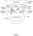
- Fig. 1 is a schematic illustration of the right atrioventricular valve (commonly referred to as the tricuspid valve).
- the tricuspid valve separates the right atrium from the right ventricle, and typically includes three leaflets, which include a posterior leaflet, an anterior leaflet, and a septal leaflet.
- the septal leaflet is positioned nearest the interventricular septum ("IVS").
- the tricuspid valve annulus may include conduction nodes near the connection point between the annulus and the septal leaflet, including for example the atrioventricular node ("AV node").
- the AV node may typically be positioned on the atrial side of the native tricuspid valve annulus.
- the left atrioventricular valve (commonly referred to as the mitral valve) may have a generally similar structure as the tricuspid valve, although many differences do exist - including for example the mitral valve typically includes two leaflets (an anterior and posterior leaflet) and has the general shape of a hyperbolic paraboloid or "saddle"-type shape.
- Both the mitral valve annulus and tricuspid valve annulus may be very large compared to the aortic and pulmonary valves.
- the tricuspid valve can range from between about 35 mm to about 65 mm in perimeter-derived diameter. However, it should be understood that these sizes are merely exemplary.
- a collapsible prosthetic mitral or tricuspid valve may have a dual-frame design.
- a first large outer frame may be used primarily to anchor and/or seal the prosthetic heart valve at the native annulus, with a second smaller inner frame connected to and positioned within the outer frame.
- the inner frame may function primarily to support one or more prosthetic valve leaflets.
- the inner frame may be generally cylindrical when implanted, with the inner and outer frames connected in a way such that forces from the native valve that deform the outer frame tend not to deform the inner frame (or at least not to a significant enough extent to reduce the ability of the prosthetic leaflets within the inner frame to properly coapt).
- Having a single large frame that serves both the anchoring/sealing function as well as directly supporting prosthetic leaflets may be undesirable in the tricuspid and mitral valves because the leaflets may need to be very large and may be more likely to be deformed during regular operation due to forces from the native annulus.
- Some embodiments described below provide the ability to have a single supporting frame for anchoring while avoiding at least some of the concerns described above for a single-frame mitral or tricuspid valve prosthesis. And while these embodiments may be suitable for either mitral or tricuspid valve replacement, they may be particularly suited for tricuspid valve replacement because of the lower forces and pressures that occur within and across the tricuspid valve compared to the mitral valve.
- Fig. 2 shows a perspective view of a collapsible and expandable prosthetic heart valve 100.
- prosthetic heart valve 100 may be suitable as a replacement for a native mitral or tricuspid valve
- prosthetic heart valve 100 is generally described below in the context of a prosthetic tricuspid valve.
- a main structural component of the prosthetic heart valve 100 is a frame 200. Portions of the frame 200 are covered by a liner or skirt material in Fig. 2 .
- frame 200 Before returning to describe other portions of the prosthetic heart valve 100, an exemplary frame 200 is described. However, it should be understood that frame 200 is merely exemplary, and other frames having generally similar overall designs may be used in place of the frame 200 without a significant deviation from the functionality of the prosthetic heart valve 100.
- FIG. 4 shows the frame 200 from a side view while in the expanded condition, with the inflow end of the frame 200 being positioned toward the top of Fig. 4 and the outflow end of the frame 200 being positioned toward the bottom of Fig. 4 .
- Frame 200 may be formed of a superelastic and/or shape memory material such as Nitinol. According to some examples, other biocompatible metals or metal alloys may be suitable.
- the frame 200 may be laser cut from a single tube, such as a shape memory metal tube.
- the shape memory metal tube may be Nitinol or any other bio-compatible metal tube.
- the frame 200 may be formed of a shape memory polymer.
- the frame 200 may be adapted to expand from a collapsed or constrained configuration to an expanded configuration.
- the frame 200 may be adapted to self-expand, although the frame could instead be partially or fully expandable by other mechanisms, such as balloon expansion.
- the frame 200 may be maintained in the collapsed configuration during delivery, for example via one or more overlying sheaths that restrict the frame from expanding.
- the frame 200 may be expanded during deployment from the delivery device once the delivery device is positioned within or adjacent to the native valve annulus.
- an atrial portion 202 and ventricular portion 204 may extend radially outward from a central longitudinal axis of the frame 200 and/or a central portion 203 of the frame 200 and may be considered to flare outward relative to the central longitudinal axis of the frame 200 and/or central portion 203.
- the atrial portion 202 and ventricular portion 204 may be considered flanged relative to central portion 203.
- the flared configuration of the atrial and ventricular portions 202, 204 and the central portion 203 may define a general hourglass shape in a side view of the frame 200.
- Atrial and ventricular portions 202, 204 may be flared outwards relative to the central portion 203 and then curve or bend to point at least partially back in the axial direction. It should be understood, however, that an hourglass configuration is not limited to a symmetrical configuration.
- Atrial portion 202 may be referred to herein as an atrial portion, an atrial cuff, or an atrial anchor.
- ventricular portion 204 may be referred to herein as a ventricular portion, a ventricular cuff, or a ventricular anchor. It should be understood that, in this context, the terms "portion,” “cuff,” and “anchor” are intended to be used interchangeably with each other.
- the frame 200 may include an atrial portion or anchor 202, a ventricular portion or anchor 204, and a central portion 203 coupling the atrial portion to the ventricular portion.
- the atrial portion and ventricular portion may be referred to herein as atrial or ventricular disks.
- Atrial portion 202 may be configured and adapted to be disposed on an atrial side of a native valve annulus and may flare radially outwardly from the central portion 203.
- Ventricular portion 204 may be configured and adapted to be disposed on a ventricular side of the native valve annulus and may also flare radially outwardly from the central portion 203.
- the central portion 203 may be configured to be situated in the valve orifice, for example in contact with the native valve annulus. In use, the atrial portion 202 and ventricular portion 204 effectively clamp the native valve annulus on the atrial and ventricular sides thereof, respectively, anchoring the prosthetic heart valve 100 in place.
- the atrial portion 202 may be formed as a portion of a stent or other support structure that includes or is formed by a plurality of generally diamond-shaped cells, although other suitable cell shapes, such as triangular, quadrilateral, or polygonal may be appropriate.
- the atrial portion 202 may be formed as a braided mesh, as a portion of a unitary stent, or a combination thereof.
- the stent that includes the atrial portion 202 may be laser cut from a tube of Nitinol and heat set to the desired shape so that the stent, including atrial portion 202, is collapsible for delivery, and re-expandable to the set shape during deployment.
- the atrial portion 202 may be heat set into a suitable shape to conform to the native anatomy of the valve annulus to help provide a seal and/or anchoring between the atrial portion 202 and the native valve annulus.
- the shape-set atrial portion 202 may be partially or entirely covered by a cuff or skirt, on the luminal and/or abluminal surface of the atrial portion 202.
- the skirt may be formed of any suitable material, including biomaterials such as bovine pericardium, biocompatible polymers such as ultra-high molecular weight polyethylene (“UHMWPE”), woven polyethylene terephthalate (“PET”) or expanded polytetrafluoroethylene (“ePTFE”), or combinations thereof.
- UHMWPE ultra-high molecular weight polyethylene
- PET woven polyethylene terephthalate
- ePTFE expanded polytetrafluoroethylene
- the atrial portion 202 may include features for connecting the atrial portion to a delivery system.
- the atrial portion 202 may include pins or tabs 222 around which sutures (or suture loops) of the delivery system may wrap so that while the suture loops are wrapped around the pins or tabs 222, the frame 200 maintains a connection to the delivery device.
- pins or tabs 222 may be completely optional.
- the ventricular portion 204 may also be formed as a portion of a stent or other support structure that includes or is formed of a plurality of diamond-shaped cells, although other suitable cell shapes, such as triangular, quadrilateral, or polygonal may be appropriate.
- the ventricular portion 204 may be formed as a braided mesh, as a portion of a unitary stent, or a combination thereof.
- the stent that includes the ventricular portion 204 may be laser cut from a tube of Nitinol and set to the desired shape (e.g., via heat treating) so that the ventricular portion 204 is collapsible for delivery, and re-expandable to the set shape during deployment.
- the ventricular portion 204 may be partially or entirely covered by a cuff or skirt, on the luminal and/or abluminal surface of the ventricular portion 204.
- the skirt may be formed of any suitable material described above in connection with the skirt of atrial portion 202. It should be understood that the atrial portion 202 and ventricular portion 204 may be formed as portions of a single support structure, such as a single stent or braided mesh. However, in other embodiments, the atrial portion 202 and ventricular portion 204 may be formed separately and coupled with one another.
- the frame 200 may be configured to expand circumferentially (and radially) and foreshorten axially as the prosthetic heart valve 100 expands from the collapsed delivery configuration to the expanded deployed configuration.
- the frame 200 may define a plurality of atrial cells 211a, 211b in two circumferential rows.
- the first row of atrial cells 211a may be generally diamond shaped and positioned on the inflow end of the frame 200.
- the second row of atrial cells 211b may be positioned at least partially between adjacent atrial cells 211a in the first row, with the atrial cells 211b in the second row being positioned farther from the inflow end than the first row of atrial cells 211a.
- the frame 200 may include twelve atrial cells 211a in the first row each having a diamond shape, and twelve atrial cells 211b in the second row each having a skewed diamond shape.
- This skewed diamond shape which is wider nearer the inflow (or top) end and narrower nearer the outflow (or bottom) end, may assist in transitioning from twelve cells per row on the atrial side of the stent to twenty-four cells per row on the ventricular side.
- the particular number, shape, and configuration of atrial cells may be different than the specific embodiment shown.
- the frame 200 may include a plurality of ventricular cells 211c in a first row, and another plurality of ventricular cells 211d in a second row.
- the first row of ventricular cells 211c may be at the outflow end of the frame 200, and the second row of ventricular cells 211d may be positioned farther from the outflow end than, and adjacent to, the first row of ventricular cells 211c.
- the first and second rows of ventricular cells 211c, 211d are all generally diamond-shaped and have substantially the same or identical size, with twenty-four cells in the first row of ventricular cells 211c and twenty-four cells in the second row of ventricular cells 211d.
- the particular number, shape, and configuration of ventricular cells may be different than the specific embodiment shown.
- Frame 200 is also illustrated as including three rows of center cells.
- a first row of center cells 211e may be positioned adjacent to the atrial end of the frame 200, each cell 211e being positioned between a pair of adjacent atrial cells 211b.
- Each center cell 211e may be substantially diamond-shaped, but it should be understood that adjacent center cells 211e do not directly touch one another.
- the first row of center cells 211e may include twelve center cells 211e, with the combination of atrial cells 211b and the center cells 211e helping transition from rows of twelve cells on the atrial side to rows of twenty-four cells on the ventricular side.
- a second row of center cells 211f may be positioned at a longitudinal center of the frame 200, each center cell 211f being positioned between an atrial cell 211b and center cell 211e.
- center cells 211f in the second row may be diamond-shaped, with the second row including twenty-four center cells 211f.
- a third row of center cells 211g may be positioned between the second row of center cells 211f and the second row of ventricular cells 211d.
- the third row of center cells 211g may include twenty-four cells and they may each be substantially diamond-shaped. However, it should be understood that the particular number, shape, and configuration of center cells may be different than the specific embodiment shown.
- All of the cells 211a-g may be configured to expand circumferentially and foreshorten axially upon expansion of the frame 200.
- a pin or tab 222 may extend from an apex of each atrial cell 211a in the first row in a direction toward the outflow end of the frame 200. Although one pin or tab 222 is illustrated in each atrial cell 211a in the first row, in other embodiments fewer than all of the atrial cells in the first row may include a pin or tab.
- These pins or tabs 222 may be configured to receive a suture or suture loop of a delivery device so that the frame 200 (and thus the prosthetic heart valve 100) remains coupled to the delivery system until the user decouples the suture loops from the pins or tabs 222.
- frame 200 may include a plurality of tines or barbs 208 extending from a center portion or ventricular portion of the frame for piercing or otherwise engaging native tissue in the native annulus or in the native leaflets.
- each barb 208 is connected to a ventricular cell 211d in the second row.
- the barb 208 may be coupled to an inflow or outflow apex of each cell.
- the barbs 208 are coupled to ventricular cells 211d on an inflow half of the cell, on either side of the inflow apex.
- the barb 208 in one ventricular cell 211d may be coupled to the inflow half of that cell on a right side of the apex, with the adjacent ventricular cell 211d having a barb coupled to the inflow half of that cell on a left side of the apex.
- the barbs 208 are provided in pairs with relatively little space between the barbs of a pair, but a relatively large space between adjacent pairs.
- the barbs 208 may in other embodiments be centered with even spacing between adjacent barbs.
- each barb 208 extends toward the outflow end of the frame, each barb being positioned within a ventricular cell 211d in the second row.
- the barbs 208 may hook upwardly back toward the inflow end, the barbs being configured to pierce native tissue of the valve annulus, such as the native leaflets, to help keep the prosthetic heart valve from migrating under pressure during beating of the heart.
- the tines or barbs 208 may be completely omitted.
- the tines or barbs 208 may be particularly helpful when used in a native mitral valve, as a prosthetic mitral valve must withstand relatively high pressures, and the tines or barbs 208 may assist with anchoring.
- the tines or barbs 208 may be omitted when the prosthetic heart valve is used as a prosthetic tricuspid valve, as pressures within the right heart are significantly lower than pressures within the left heart, and thus the tines or barbs 208 may not be needed at all for anchoring.
- the tines or barbs 208 may increase the likelihood of conduction disturbances, and particularly in the context of a prosthetic tricuspid valve, it may be preferable to omit the tines or barbs 208 entirely.
- a typical prosthetic atrioventricular valve may include an inner metal frame to which prosthetic leaflets are attached.
- prosthetic heart valve 100 may completely omit any inner metallic or otherwise rigid frame to which the prosthetic leaflets are attached.
- prosthetic heart valve 100 omits an inner metallic or otherwise rigid frame, and instead includes a soft tube 300 that is secured to the frame 200.
- the tube 300 may be formed of any suitable biocompatible material, including for example PET, PTFE, ePTFE, UHMWPE, etc ., including in a fabric form or another form, including extruded or flat sheet polymers.
- the tube 300 may be formed of tissue, such as bovine or porcine pericardium.
- the material e.g ., fabric or tissue
- a plurality of prosthetic leaflets 400 may be coupled directly to the tube 300, for example by suturing.
- the prosthetic heart valve 100 includes three leaflets 400, with each leaflet including a free edge 410 and an attached edge 420.
- the free edges 410 move away from each other to allow for blood to flow through the tube 300 and the leaflets 400 in the antegrade direction (i.e ., from the atrium to the ventricle), and coapt together to restrict blood from flowing through the tube 300 in the retrograde direction ( i.e ., from the ventricle to the atrium).
- the attached edge 420 may be opposite the free edge 410 and may be attached to the tube 300 via any suitable mechanism, including fasteners such as sutures. In the illustrated embodiment, the attached edges 420 generally follow a "U"-shaped, catenary, or generally parabolic pattern.
- the prosthetic leaflets 400 are formed of bioprosthetic tissue, such as bovine or porcine pericardium, but in other embodiments, the prosthetic leaflets 400 may be formed of fabrics or other synthetic materials, such as PET, PTFE, UHMWPE, etc.
- the prosthetic heart valve 100 may include a covering or lining, such as a skirt 500.
- Skirt 500 may be formed of any suitable material, including tissue, fabric, or extruded or flat sheet polymers.
- skirt 500 may be formed of a woven synthetic fabric such as PET, PTFE, UHMWPE, etc. that functions to contact native tissue at or adjacent to the native heart valve annulus and provide a conforming seal.
- skirt 500 may include an outer or peripheral section 510 attached to the luminal or abluminal (as shown in Fig. 2 ) surface of the frame 200, for example via suturing.
- the outer section 510 of the skirt 500 preferably contacts the native valve annulus to help seal against the native valve annulus and to prevent paravalvular leakage around the prosthetic heart valve 100.
- the skirt 500 may also include an outflow section 520 generally extending radially inwardly from the frame 200 to the tube 300.
- the outflow section 520 may be formed of the same or different materials as the peripheral or outer section 510 of the skirt 500, and for example, may be substantially impermeable to blood flowing therethrough.
- the outflow section 520 in the embodiment shown in Fig.
- the skirt 500 may also include an inflow section that is substantially similar to the outflow section, with the exception that it is positioned on the inflow section of the prosthetic heart valve 100 (which is not visible in the view of Fig. 2 ).
- the inflow section may be generally annular with an outer perimeter or circumference attached to the frame 200 and an inner perimeter of circumference attached to the outer perimeter of the inflow end of tube 300.
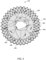
- Fig. 3 shows the prosthetic heart valve 100 of Fig. 2 prior to the prosthetic leaflets 400 being attached to the tube 300.
- Fig. 3 shows particularly well one mechanism by which the tube 300 may be coupled to the prosthetic heart valve 100.
- the inflow and outflow ends of the tube 300 may be coupled to the inner perimeters of the inflow and outflow sections of skirt 500, those couplings may be primarily to help ensure that blood only flows through the lumen of tube 300. It may be desirable to provide additional structural support for the tube 300, particularly since the prosthetic leaflets 400 therein will need to resist significant forces when they close during ventricular systole.
- one or more connectors 600 may directly couple the tube 300 to the frame 200.
- FIG 3 illustrates a plurality of radially extending sutures 600, each suture 600 having a first end coupled to the frame 200 and a second end coupled to the tube 300, with the suture 600 generally extending along a line that would pass through (or nearly pass through) a radial center of the tube 300.
- one group of sutures 600 is provided at the outflow end of the prosthetic heart valve 100, and although not shown, a generally similar or identical group of suture connectors 600 is provided at the inflow end of the prosthetic heart valve 100, so that both the inflow and outflow ends of the tube 300 are secured to the frame 200 via radially extending sutures 600.
- the suture connectors 600 may only provide support in tension, and thus help to minimize the movement of the inner valve (e.g ., the tube 300 with the prosthetic leaflets 400 coupled thereto) during normal operation of the prosthetic heart valve 100.
- the frame 200 is compressed ( e.g ., when being collapsed for delivery, or when the native tissue applies force to the frame 200 during the normal cycle of the heart), that compressive force is not translated via the suture connectors 600 to the tube 300.
- a tensioning mechanism may be provided with one or more of the suture connectors 600 to allow for adjusting the tension of the suture connectors 600 during or after delivery and deployment of the prosthetic heart valve 100.
- a suitable tensioning mechanism is a ratcheting mechanism, with a portion of the suture connectors having a feature that slides against the connection point in only one direction to tighten.
- a mechanism that knots, swages, or pins at the connection point may be used when the desired tension and/or annular motion is reached.
- suture connector the connectors are not actually limited to sutures - but may be any suitable cord, string, or wire-like material that is sufficiently strong to provide the desired support to the inner valve.
- suture connectors 600 may be only one example of how the tube 300 may be coupled to the frame 200.
- rigid arms such as arms formed of nickel-titanium alloy or Nitinol, may be incorporated into the frame 200 with the arms being bent inwardly to form a general "C" shape with the ends of the "C” shape coupled to the top and bottom, respectively, of the tube 300.
- suitable arm connectors are described in greater detail in U.S. Patent Application No. 18/067,993 titled “Two Stage Tricuspid Valve Implant” and filed on December 19, 2022 .
- Such connector arms may provide more rigid support than the suture connectors 600.
- prosthetic heart valve 100 lacks a metallic or otherwise rigid inner frame for supporting the prosthetic leaflets 400 that is frequently found in collapsible and expandable prosthetic atrioventricular valves.
- the prosthetic heart valve 100 is able to collapse to a smaller size (e.g ., a smaller French size) and thus a smaller catheter may be used to deliver the prosthetic heart valve 100, compared to an otherwise similar prosthetic heart valve that includes a metallic or otherwise rigid inner frame. It is generally desirable to use smaller catheters, when possible, to deliver a prosthetic heart valve via a transvascular route since larger catheters may present a greater risk to the patient, particularly at the access site ( e.g ., the femoral vein).
- This design may also reduce the forces required to load the prosthetic heart valve into the delivery device.
- a smaller force may be required to collapse the valve which is generally desirable.
- other benefits may arise from the single-frame design of prosthetic heart valve 100. For example, retrieving a prosthetic heart valve after it has been partially or completely deployed into the native valve annulus can be very difficult when two separate rigid frames are used.
- the use of two separate rigid frames may increase the forces required to retrieve ( e.g ., by re-collapsing) the prosthetic heart valve, and the existence of two spaced apart rigid frame structures may create a greater likelihood of frame structure getting "caught" on a retrieval catheter as the prosthetic heart valve is being re-collapsed into the retrieval catheter.
- Forming the prosthetic heart valve 100 with only a single rigid frame may reduce or eliminate both of these potential issues.
- Still another potential benefit of the single frame design of prosthetic heart valve 100 is that, because there is no rigid connection between the prosthetic leaflets 400 and the frame 200 that is directly in contact with the native valve, any deformation of the frame 200 during normal operation of the prosthetic heart valve 100 is highly unlikely to result in any deformation of the prosthetic leaflets 400.
- Deformation of the prosthetic leaflets 400 is undesirable because any deformation to the shape of the prosthetic leaflets 400 during operation may negatively affect the ability of the prosthetic leaflets 400 to properly coapt and to create a complete seal during ventricular systole. In other words, if the deformation of the frame 200 caused deformation of the prosthetic leaflets 400, the prosthetic heart valve 100 may allow for undesirable regurgitation across the prosthetic leaflets 400.
- prosthetic heart valve 100 is described above as having prosthetic leaflets 400 directly attached ( e.g ., via sutures) to the tube 300
- additional support materials may be provided at the leaflet-tube interface.
- an underwire type of structure may be attached to the tube 300, and portions of the prosthetic leaflets 400 attached to the underwire, to provide additional support.
- the underwire may take the form of wire, such as a strand of Nitinol, that has a general "U"-shape corresponding to each prosthetic leaflet 400.
- a Nitinol underwire that follows the general contours of the attachment edge 420 may be interposed between the prosthetic leaflets 400 and the tube 300.
- the underwire may be substantially continuous so that the prosthetic leaflets 400 are attached to the underwire along the leaflet bellies ( e.g ., along attachment edge 420), as well as the commissures where adjacent prosthetic leaflets 400 join.
- only the leaflet bellies may be attached to an underwire provided on the tube 300.
- only the leaflet commissures may be attached to an underwire (or another support structure, such as a commissure plate) on the tube 300.
- these additional support structures may offer a compromise in the sense that, while the additional metal (or otherwise rigid) material on the tube 300 may increase bulk, it may only increase bulk slightly compared to the use of a full inner metal stent, but the additional support to the prosthetic leaflets 400 may justify the additional bulk created.
- prosthetic heart valve 100 is described and shown in connection with Figs. 2-4 as including prosthetic leaflets 400 attached to the tube 300, in some embodiments, the tube itself may function as a valve without the need for separate leaflets.
- Fig. 5 illustrates a prosthetic heart valve 100' that is similar to prosthetic heart valve 100 in a number of respects.
- prosthetic heart valve 100' may include frame 200, which may be similar or identical to frame 200 described above.
- the frame 200 of prosthetic heart valve 100' may take other suitable forms besides the particular features described in connection with frame 200.
- prosthetic heart valve 100' may include a tube 300' of soft material, such as tissue or fabrics as described in connection with tube 300'.
- prosthetic heart valve 100 and 100' The main difference between prosthetic heart valve 100 and 100' is that the tube 300' itself provides the valving functionality, without the need for separate leaflets.
- the inflow end of tube 300' (toward the bottom in the view of Fig. 5 ) may be coupled to the frame 200 in substantially the same fashion as described in connection with prosthetic heart valve 100.
- a plurality of connectors 600 which may be suture or suture-like connectors 600, extend radially outwardly from the inflow end of the tube 300' to the frame 200 to provide connection points therebetween.
- Each suture connector 600 may have a first end coupled to the inflow end of the tube 300' and a second end coupled to the frame 200, with the suture connectors 600 generally extending in a direction toward the radial center of the tube 300'.
- enough suture connectors 600 are provided on the inflow end of the tube 300' to ensure that the inflow end of the tube 300' cannot close or otherwise collapse on itself.
- 4, 5, 6, 7, 8, 9, or more suture connectors 600 may connect the inflow end of the tube 300' to the frame 200.
- the suture connectors 600 are positioned at substantially equal intervals around the circumference of the inflow end of the tube 300'.
- the outflow end of the tube 300' has fewer suture connectors 600.
- the outflow end of the tube 300' has exactly two suture connectors 600 that connect the outflow end of the tube 300' to the frame 200, with the two suture connectors 600 being positioned at diametrically opposed points of the outflow end of the tube 300'.
- the two suture connectors 600 at the outflow end of the tube 300' will maintain the position of the connection points of the tube 300' relative to the frame 200.
- the outflow end of the tube 300' excludes additional suture connectors 600, the unconnected or free edges of the outflow end of the tube 300' are generally free to open and close depending on the pressure gradient across the prosthetic heart valve 100'.
- arrows 610 illustrate that the outflow end of the tube 300' will tend to close on each other on either side of the pair of suture connectors 600, much like a duckbill valve.
- the outflow end of the tube 300' will tend to close along the 6 o'clock and 12 o'clock directions when the pressure in the ventricle is greater than the pressure in the atrium.
- the tube 300' may be formed as a single generally cylindrical piece of fabric or tissue (e.g ., tissue that is rolled into a tube shape), or two separate pieces of fabric or tissue sewn together with opposing seams. If the tube 300' is formed as two pieces of material sutured together at opposing seams (e.g ., seams running vertically or longitudinally), it may be preferable for the suture connectors 600 at the outflow end of the tube 300' to connect at or near the seams, so that the outflow end of the tube 300' opens and closes between the seams.
- prosthetic heart valve 100' may include a skirt substantially similar or identical to skirt 500.
- a skirt 620 may be generally at the outflow end of prosthetic heart valve 100', but with a center portion of the skirt 620 angled or oriented toward the inflow end, with the tube 300' extending through a center portion of the skirt 620.
- the skirt 620 at the outflow end could be omitted.
- a skirt may be provided at the inflow end of the prosthetic heart valve 100' as well.
- the outflow skirt e.g .
- skirt 500 is provided at the outflow most end of the leaflet assembly, or even downstream of the leaflets.
- the outflow end of the tube 300' acts as the valve, and includes edges that are in motion, the outflow skirt 620 cannot be directly attached to the outflow end of the tube 300', as such connection could interfere with the opening and closing of the outflow end of the tube 300'.
- the center portion of the skirt 620 is coupled to the tube 300' at a spaced distance away from the outflow end of the tube 300' to allow the outflow end of the tube 300' to open and close during normal operation.
- FIG. 6A-B illustrate the prosthetic heart valve 100 deployed into a test system that simulates flow through the prosthetic heart valve 100.
- the inflow side of the prosthetic heart valve 100 is toward the right of the views and the outflow side of the prosthetic heart valve is toward the left of the views.
- Fig. 6A-B illustrate the prosthetic heart valve 100 deployed into a test system that simulates flow through the prosthetic heart valve 100.
- the inflow side of the prosthetic heart valve 100 is toward the right of the views and the outflow side of the prosthetic heart valve is toward the left of the views.
- FIG. 6A illustrates a portion of the test in which the fluid pressure on the inflow (right) side of the prosthetic heart valve 100 is greater than on the outflow (left) side of the prosthetic heart valve 100, forcing the prosthetic leaflets 400 to open to allow fluid to flow through the tube 300.
- Fig. 6B illustrates a portion of the test in which the fluid pressure on the outflow (left) side of the prosthetic heart valve 100 is greater than on the inflow (right) side of the prosthetic heart valve 100, forcing the prosthetic leaflets 400 to close to prevent fluid from flowing backward through the tube 300.
- the tube 300 may have a length in the axial direction between the inflow and outflow ends, and the maximum displacement of the tube 300 during a single cycle of the heart may be between about 20% and about 60%, including about 30%, about 40%, or about 50% of the length of the tube 300.
- Prosthetic heart valves intended for use in replacing a tricuspid (i.e ., right atrioventricular) valve may include additional or alternative features than those described above particularly suited for use in the tricuspid space.
- a tricuspid valve replacements one concern that is of particular interest with tricuspid valve replacements is the fact that the AV node is typically located within the right atrium, and prosthetic tricuspid valves with an atrial cuff may be at risk of pressing against the AV node which may disturb the natural conduction system of the heart.
- the tricuspid valve annulus is typically (but not necessarily always) larger than the annuli of the remaining heart valves (mitral, aortic, and pulmonary).
- Fig. 7A illustrates a highly schematic view of a prosthetic tricuspid valve system 1000 implanted in a native tricuspid valve, with the heart being shown in a cutaway view.
- the prosthetic tricuspid valve system 1000 may generally include three components, including a prosthetic valve 1100 to provide the replacement valve functionality, an anchor 1200 to serve as an anchor point for the prosthetic tricuspid valve system 1000, and a connecting line or tether 1300 to couple the prosthetic valve 1100 to the anchor 1200.
- Fig. 7B is an isolated schematic view of the prosthetic valve 1100 of the valve system 1000.
- the prosthetic valve 1100 may include a collapsible and expandable stent or frame 1110.
- Frame 1110 may be formed of a shape memory metal or metal alloy such as Nitinol, and may be formed as a braided mesh or an integral member, for example laser cut from a tube of Nitinol and then heat treated to establish the desired shape in the expanded condition.
- the frame 1110 when in the expanded condition shown in Fig. 7B , may include a main portion that is generally cylindrical, a set of prosthetic leaflets 1120 being received within and coupled to the main portion.
- the prosthetic leaflets 1120 may be substantially similar or identical to prosthetic leaflets 400 described above.
- the main portion of the frame 1110 may transition to a connector 1130, the connector 1130 coupling the tether 1300 to the frame 1110.
- the transition may include a plurality (e.g ., three) of individual struts that have first ends connected to the main portion of the frame 1110 and which converge to a central portion which is the connector 1130.
- the connector 1130 is not a separate structure and is simply the point of fixation between the tether 1300 and the frame 1110.
- specialized features may be provided for connector 1130, an example of which is described in greater detail below.
- the prosthetic valve 1100 may also include an outer frame 1140 coupled to the inner frame 1110.
- the outer frame 1140 may be sutured or otherwise fastened to the inner frame 1110.
- the outer frame 1140 and the inner frame 1110 may not be separate structures, but rather formed integrally, for example via laser cutting from a single tube of Nitinol.
- the prosthetic valve 1100 may be asymmetric and have a single intended orientation for implantation.
- the outer frame 1140 may include two main valve anchoring features, including a hook 1142 and a shelf 1144.
- the hook 1142 may be referred to as a right ventricular outflow tract (“RVOT”) hook 1142, and is intended to hook over the outflow side of the native tricuspid valve leaflets adjacent to the RVOT, which is generally the area through which blood flows from the right ventricle through the pulmonary valve.
- RVOT hook 1142 The intended position of the RVOT hook 1142 is best shown in Fig. 7A .
- the RVOT hook 1142 may extend from the main portion of the frame 1110 in the outflow direction, extending radially outward from the center of the prosthetic valve 1100 and then hooking back toward the inflow direction of the prosthetic valve 1100.
- the shelf 1144 which may be referred to as a posterior shelf, is generally similar in overall shape and structure to the RVOT hook 1142, but extends from the diametrically opposed portion of the prosthetic valve 1100, as best shown in Figs. 7A and 7C .
- posterior shelf 1144 is positioned on the outflow or ventricular side of the native tricuspid valve after deployment, but extends generally toward the right ventricular wall (the ventricular wall opposite the intraventricular septum).
- posterior shelf 1144 may extend from the main portion of the frame 1110 in the outflow direction, extending radially outward from the center of the prosthetic valve 1100 and then hooking back toward the inflow direction of the prosthetic valve 1100.
- Fig. 7C is a top view of prosthetic heart valve 1110, as viewed from the inflow-to-outflow direction.
- the outer frame 1140 is a separate component from the frame 1110, and generally surrounds the frame 1110 and is fastened to the frame 1110 ( e.g ., via sutures).
- the portions of the outer frame 1140 between the RVOT hook 1142 and the posterior shelf 1144 may be relatively thin and mainly intended to provide a structure that connects to the RVOT hook 1142 and posterior shelf 1144.
- the RVOT hook 1142 may extend a distance radially away from the center of the prosthetic heart valve 1100 greater than the radial distance that the posterior shelf 1144 extends from the center of the prosthetic heart valve 1100.
- the RVOT hook 1142 may be narrower compared to the posterior shelf 1144.
- the width of the posterior shelf 1144 measured in a direction orthogonal to the flow direction of the prosthetic valve 1100 and perpendicular to the directions in which the RVOT hook 1142 and posterior shelf 1144 extend, may be greater than the width of the RVOT hook 1142 measured in the same direction.
- the RVOT hook 1142 and posterior shelf 1144 when the prosthetic heart valve 1100 is deployed in the native tricuspid valve annulus, mainly function to provide a force that counters the tension from tether 1300, described in greater detail below.
- the RVOT hook 1142 and posterior shelf 1144 may assist with sealing the prosthetic valve 1100 against the native tricuspid valve annulus
- the main purpose is to provide an anchoring force against migration of the prosthetic heart valve 1100 into the right atrium.
- the prosthetic heart valve 1100 may include any suitable skirt or sealing member on outer surfaces thereof to contact the native anatomy to help with sealing against paravalvular leak.
- the only anchoring features of the prosthetic heart valve 1100 that result in direct contact with the native tricuspid valve annulus are the RVOT hook 1142 and posterior shelf 1144, which contact the outflow or ventricular side of the native tricuspid valve. Also, to the extent that the self-expansion force of the main body of the prosthetic heart valve 1100 in the native tricuspid annulus provides additional anchoring, the contact is generally only with the inner surface of the native tricuspid valve annulus.
- the prosthetic heart valve 1100 may be anchored within the native tricuspid valve without any atrial cuff that is typical of a prosthetic tricuspid valve.
- the AV node is typically located on the atrial side of the native tricuspid valve annulus near the atrial septum.
- the anchoring described and shown in connection with Figs. 7A-C completely avoids contact with the AV node, reducing the likelihood of conduction disturbances that might result in the prosthetic heart valve 1100 contacting or otherwise pressing against the AV node.
- Fig. 7D illustrates the anchor 1200 of the tricuspid valve system 1000 deployed within the superior vena cava SVC.
- Anchor 1200 may take the form of a collapsible and expandable stent.
- the anchor 1200 may be balloon expandable and formed of a plastically expandable material such as stainless steel or cobalt chrome.
- the anchor 1200 may be self-expandable and formed of a shape memory material such as Nitinol.
- anchor 1200 is generally cylindrical when expanded and thus does not disrupt (or does not materially disrupt) the flow of blood through the superior vena cava SVC.
- the anchor 1200 is self-expandable, the anchor 1200 is preferably oversized so that, in the absence of applied forces, the outer diameter of the anchor 1200 is larger than the inner diameter of the superior vena cava SVC.
- the anchor 1200 may be "oversized" relative to the superior vena cava SVC so that, when the anchor 1200 self-expands into the superior vena cava SVC, the anchor 1200 at least slightly deforms the shape of the superior vena cava SVC to help prevent axial migration of the anchor 1200. This local deformation of the superior vena cava SVC can be seen in Fig. 7D .
- the anchor 1200 is balloon expandable, the balloon (or other mechanism that forces the anchor 1200 to radially expand), may be used to expand the anchor 1200 until it has a diameter that is slightly larger than the natural inner diameter of the superior vena cava SVC.
- the anchor 1200 may be generally cylindrical in the expanded condition
- the anchor preferably includes a feature to assist with the connection of the tether 1300 to the anchor 1200.
- the outflow end of the anchor 1200 (which is positioned closest to the right atrium upon deployment into the superior vena cava SVC) may include an arch 1210 that the tether 1300 may be looped around, as described in greater detail below.
- Fig. 7E illustrates the anchor 1200 in isolation in an expanded condition, showing the arch 1210 that extends beyond the outflow end of the main cylindrical portion of the anchor 1200.
- arch 1210 may be formed as a single strut or strand of metal that has ends coupled to diametrically opposed points of the anchor 1200, similar to a handle of a bucket.
- arch 1210 is shown as a generally arcuate member, in some embodiments it may be more "V"-shaped which may assist with the arch 1210 more easily collapsing for delivery. It should be understood that other shapes and configurations of arch 1210 may be suitable.
- arch 1210 is described in connection with looping of the tether 1300 around the arch 1210 to connect the tether 1300 to the anchor 1200, as described in greater detail below, it should be understood that any mechanism for connecting the tether 1300 to the anchor 1200 may be suitable.
- Figs. 7F-H illustrate different stages in the delivery and deployment of prosthetic tricuspid valve system 1000 into a patient's heart.
- the anchor 1200 may be loaded into a catheter 1400 of a delivery device in a collapsed condition.
- the catheter 1400 may be passed into the patient, for example through an access site in the femoral vein, and the catheter 1400 may be advanced through the inferior vena cava IVC, into the right atrium, and then into the superior vena cava SVC.
- the anchor 1200 When the distal end of the catheter 1400 has reached the desired distance within the superior vena cava SVC, the anchor 1200 may be deployed from the catheter 1400 and transitioned into the expanded condition shown in Fig. 7F .
- the anchor 1200 may be loaded over an inflatable balloon and the balloon may be inflated to force the anchor 1200 to expand into the superior vena cava SVC.
- the anchor 1200 may be advanced distally relative to the distal end of the catheter 1400, and the anchor 1200 will self-expand as the catheter 1400 uncovers the anchor 1200.
- the mechanism by which the anchor 1200 is advanced relative to the catheter 1400 may be any suitable mechanism.
- an interior pusher may be pushed distally to push the anchor 1200 out of the catheter 1400.
- the anchor 1200 may be releasably coupled to an inner catheter shaft, and the catheter 1400 may be withdrawn proximally relative to the anchor 1200 until the anchor 1200 self-expands away from the inner catheter shaft.
- the anchor 1200 is preferably expanded to a size that has a larger diameter than the natural inner diameter of the superior vena cava SVC, as described above, with the arch 1210 facing in the outflow direction ( i.e ., toward the right atrium).
- the stent 1200 is delivered in isolation without being connected to either the tether 1300 or the prosthetic heart valve 1100 at the time of deployment of the stent 1200.
- the prosthetic valve 1100 may be delivered and deployed next.
- the same catheter 1400 that delivered the anchor 1200 may be used to deliver the prosthetic valve 1100.
- the prosthetic valve 1100 may be pre-loaded into the catheter 1400 in a collapsed condition in a position proximal to the anchor 1200.
- the catheter used to deliver the prosthetic valve 1100 may be a separate catheter.
- the same part number 1400 is used to describe the catheter that delivers the prosthetic heart valve 1100.
- the catheter 1400 may be positioned or re-positioned so that the distal end of the catheter 1400 is at or adjacent to the native tricuspid valve.
- the prosthetic valve 1100 is oriented so that the RVOT hook 1142 and the posterior shelf 1144 are at the leading end of the prosthetic valve 1100.
- the RVOT hook 1142 and posterior shelf 1144 do not radially overlap the main body of frame 1110.
- the prosthetic heart valve 1100 may be deployed. Similar to the anchor 1200, the deployment of the prosthetic heart valve 1100 may include withdrawing the catheter 1400 while the prosthetic heart valve 1100 maintains its position, pushing the prosthetic heart valve 1100 distally out of the catheter 1400, or a combination of the two.
- the first portions of the prosthetic heart valve 1100 that exit the catheter 1400 are the RVOT hook 1142 and the posterior shelf 1144.
- the RVOT hook 1142 and posterior shelf 1144 will tend to revert to their shape-set conditions, causing the RVOT hook 1142 and posterior shelf 1144 to "hook" backward after exiting the catheter 1400.
- the RVOT hook 1142 and posterior shelf 1144 hook backward during deployment, they hook over the outflow portion of the native tricuspid valve annulus, which may include native tricuspid valve leaflets.
- Tether 1300 may be in the form of any string-like or wire-like structure that is biocompatible and is capable of withstanding tension that would otherwise tend to push the prosthetic heart valve 1100 into the right ventricle.
- tether 1300 may be a metal structure, such as a monofilament or a multifilament, including for example Nitinol.
- Tether 1300 may alternatively be formed of a polymer, such as one or more strands or filaments or threads of PE, PTFE, UHMWPE, etc.
- the tether 1300 is formed as a braided polymer.
- the tether 1300 may include a first end portion that is fixed to the prosthetic valve 1100 prior to the prosthetic heart valve 1100 being loaded into the catheter 1400.
- the connector 1130 of the frame 1110 may include a generally cylindrical stent section which may be sized to receive an end of the tether 1300, with the connector 1130 being clamped over and/or fastened ( e.g ., by sutures) to the tether 1300 positioned therein. Examples of connectors 1130 for receiving tethers are described in greater detail in U.S. Patent No. 10,405,976 .
- the tether 1300 may already be coupled or otherwise fixed to the prosthetic heart valve 1100 with the tether 1300 trailing (or being positioned generally proximal to) the prosthetic heart valve 1100.
- the tether 1300 may have a length to extend to a handle of a delivery device or beyond a handle during the delivery of the prosthetic heart valve 1100.
- the RVOT hook 1142 and posterior shelf 1144 may begin to hook backward and into contact with the ventricular or outflow side of the native tricuspid valve annulus. This contact is generally responsible for the prosthetic heart valve 1100 resisting migration into the right atrium. As the catheter 1400 is withdrawn farther relative to the prosthetic heart valve 1100, the remaining portions of the prosthetic heart valve 1100 (including the main body of the frame 1110 and the prosthetic leaflets 1120) may expand within the tricuspid valve annulus and begin to replace the functionality of the native tricuspid valve. Fig.
- FIG. 7H illustrates a further step in the procedure in which the catheter 1400 is further withdrawn and the prosthetic heart valve 1100 is allowed to fully expand into the native tricuspid valve.
- the catheter 1400 may be maneuvered so that the tether 1300, which is already fixed to the prosthetic heart valve 1100 and which extends through the catheter 1400 proximally, is looped around the arch 1210 of the anchor 1200. After the tether 1300 is looped around the arch 1210, the tether 1300 may be pulled proximally to tension the tether 1300, for example by manipulating the free end of the tether that is coupled to the delivery device or otherwise available for manipulation outside the patient's body.
- the arch 1210 generally acts like a pulley, and tension on the tether 1300 may be increased pulling the RVOT hook 1142 and posterior shelf 1144 tighter against the outflow side of the native valve annulus.
- the tether 1300 may then be affixed to the arch 1210 of the anchor 1200, for example via a knot, a separate accessory feature, or a barb-like feature built into the arch 1210.
- the tension on the tether 1300 is effectively “locked,” with the tether 1300 preventing the prosthetic heart valve 1100 from migrating into the right ventricle, and the RVOT hook 1142 and posterior shelf 1144 preventing the prosthetic heart valve 1100 from migrating into the right atrium.
- the prosthetic heart valve 1100 may be fully and satisfactorily anchored in the native tricuspid valve without any stent structure hooked around or otherwise contacting the inflow side of the native tricuspid valve, particularly in the area of the AV node.
- Fig. 7I is a schematic view of an alternate version of the anchor 1200' that includes a tether connection mechanism 1210' different than the arch 1210 of Fig. 7E .
- a portion of anchor 1200' is shown in Fig. 7I , with the anchor 1200' converging to a tether connection mechanism 1210' generally in the form of a cylinder that the tether 1300 passes through.
- a tine or barb 1220' which may be a piece of metal (e.g., Nitinol) that is integral with the remainder of the anchor 1200', extends upwardly and inwardly from the tether connection mechanism 1210'.
- the tine or barb 1220' has a sharp tip capable of digging into the tether 1300, for example if the tether 1300 is formed of a polymer.
- the tine 1220' is angled so that, if the tether 1300 is pulled in a first direction T1 aligned with the angle of the tine 1220', the tether 1300 can generally freely translate through the connection mechanism 1210', resulting in tension being added to the tether 1300.
- the tine 1220' digs into the tether 1300, preventing the tether 1300 from translating any significant distance in the direction T2.
- the tether 1300 may be pulled to the desired tension, and then upon reaching the desired tension, the tether 1300 may be released at which point the tine 1220' will engage the tether 1300 and lock the tether 1300 at the desired tension.
- the remaining length of the tether 1300 extending beyond the anchor 1200 or 1200' may be cut and removed from the body, for example via a cautery tool introduced into the heart.
- the prosthetic heart valve 1100 may be rotatable about a central longitudinal axis prior to or during deployment.
- the RVOT hook 1142 is intended to be positioned at or near the RVOT
- the posterior shelf 1144 is intended to be positioned toward the ventricular wall opposite the interventricular septum. If the RVOT hook 1142 and posterior shelf 1144 are not in the desired rotational orientation prior to (or during) deployment, it may be desirable to have a mechanism to rotate the prosthetic heart valve 1100 to the desired rotational orientation relative to the native tricuspid valve.
- prosthetic heart valve 1100 is releasably coupled to an internal shaft or catheter during deployment, that internal shaft may be rotatable (e.g., via manipulation of a handle of the delivery device) to re-orient the prosthetic heart valve 1100 into the desired rotational position.
Landscapes
- Health & Medical Sciences (AREA)
- Engineering & Computer Science (AREA)
- Biomedical Technology (AREA)
- Cardiology (AREA)
- Oral & Maxillofacial Surgery (AREA)
- Transplantation (AREA)
- Heart & Thoracic Surgery (AREA)
- Vascular Medicine (AREA)
- Life Sciences & Earth Sciences (AREA)
- Animal Behavior & Ethology (AREA)
- General Health & Medical Sciences (AREA)
- Public Health (AREA)
- Veterinary Medicine (AREA)
- Prostheses (AREA)
Applications Claiming Priority (1)
| Application Number | Priority Date | Filing Date | Title |
|---|---|---|---|
| US202263376493P | 2022-09-21 | 2022-09-21 |
Publications (2)
| Publication Number | Publication Date |
|---|---|
| EP4342425A1 true EP4342425A1 (de) | 2024-03-27 |
| EP4342425B1 EP4342425B1 (de) | 2025-04-09 |
Family
ID=87762968
Family Applications (1)
| Application Number | Title | Priority Date | Filing Date |
|---|---|---|---|
| EP23192960.5A Active EP4342425B1 (de) | 2022-09-21 | 2023-08-23 | Prothetische trikuspidalherzklappe |
Country Status (2)
| Country | Link |
|---|---|
| US (1) | US20240091000A1 (de) |
| EP (1) | EP4342425B1 (de) |
Families Citing this family (23)
| Publication number | Priority date | Publication date | Assignee | Title |
|---|---|---|---|---|
| JP2008513060A (ja) | 2004-09-14 | 2008-05-01 | エドワーズ ライフサイエンシーズ アーゲー | 心臓弁逆流の処置のためのデバイスおよび方法 |
| US20090276040A1 (en) | 2008-05-01 | 2009-11-05 | Edwards Lifesciences Corporation | Device and method for replacing mitral valve |
| WO2010057262A1 (en) | 2008-11-21 | 2010-05-27 | Percutaneous Cardiovascular Solutions Pty Limited | Heart valve prosthesis and method |
| EP4119098A1 (de) | 2009-04-15 | 2023-01-18 | Edwards Lifesciences CardiAQ LLC | Gefässimplantat und freisetzungssystem |
| CA2760461C (en) | 2009-04-29 | 2014-10-07 | The Cleveland Clinic Foundation | Apparatus and method for replacing a diseased cardiac valve |
| US8449599B2 (en) | 2009-12-04 | 2013-05-28 | Edwards Lifesciences Corporation | Prosthetic valve for replacing mitral valve |
| US8579964B2 (en) | 2010-05-05 | 2013-11-12 | Neovasc Inc. | Transcatheter mitral valve prosthesis |
| WO2012040655A2 (en) | 2010-09-23 | 2012-03-29 | Cardiaq Valve Technologies, Inc. | Replacement heart valves, delivery devices and methods |
| US12502276B2 (en) | 2011-05-16 | 2025-12-23 | Edwards Lifesciences Corporation | Inversion delivery device and method for a prosthesis |
| US9439763B2 (en) | 2013-02-04 | 2016-09-13 | Edwards Lifesciences Corporation | Prosthetic valve for replacing mitral valve |
| WO2015127283A1 (en) | 2014-02-21 | 2015-08-27 | Cardiaq Valve Technologies, Inc. | Delivery device for controlled deployement of a replacement valve |
| US9532870B2 (en) | 2014-06-06 | 2017-01-03 | Edwards Lifesciences Corporation | Prosthetic valve for replacing a mitral valve |
| WO2016153918A1 (en) | 2015-03-20 | 2016-09-29 | Cardiokinetix, Inc. | Systems and methods for delivering an implantable device |
| US10441416B2 (en) | 2015-04-21 | 2019-10-15 | Edwards Lifesciences Corporation | Percutaneous mitral valve replacement device |
| US10350062B2 (en) | 2016-07-21 | 2019-07-16 | Edwards Lifesciences Corporation | Replacement heart valve prosthesis |
| US10639143B2 (en) | 2016-08-26 | 2020-05-05 | Edwards Lifesciences Corporation | Multi-portion replacement heart valve prosthesis |
| EP3648708A4 (de) | 2017-07-06 | 2021-03-31 | Edwards Lifesciences Corporation | Steuerbares abgabesystem und komponenten |
| EP3720390B1 (de) | 2018-01-25 | 2024-05-01 | Edwards Lifesciences Corporation | Einführsystem zur unterstützten rückgewinnung oder neupositionierung eines klappenersatzes nach dem einsetzen |
| EP3921012A1 (de) | 2019-02-04 | 2021-12-15 | Edwards Lifesciences Corporation | Führungsdrahtvorrichtungen und verfahren |
| EP3952790A1 (de) | 2019-04-12 | 2022-02-16 | W.L. Gore & Associates, Inc. | Ventil mit mehrteiligem rahmen und zugehörigen elastischen überbrückungsmerkmalen |
| ES2982566T3 (es) | 2019-04-23 | 2024-10-16 | Edwards Lifesciences Corp | Sistema de suministro de implantes motorizado |
| WO2022132569A1 (en) | 2020-12-18 | 2022-06-23 | Edwards Lifesciences Corporation | Storage jar assembly for aprosthetic heart valve |
| KR102918984B1 (ko) | 2021-10-27 | 2026-01-28 | 에드워즈 라이프사이언시스 코포레이션 | 인공 심장 판막의 클림핑 및 로딩을 위한 시스템 및 방법 |
Citations (4)
| Publication number | Priority date | Publication date | Assignee | Title |
|---|---|---|---|---|
| US20130338766A1 (en) * | 2012-06-19 | 2013-12-19 | Boston Scientific Scimed, Inc. | Replacement Heart Valve |
| US20140194983A1 (en) * | 2013-01-08 | 2014-07-10 | Medtronic, Inc. | Valve Prosthesis and Method for Delivery |
| FR3043907A1 (fr) * | 2015-11-23 | 2017-05-26 | Alain Dibie | Assemblage pour le remplacement de la valve atrio-ventriculaire tricuspide |
| US10405976B2 (en) | 2013-05-30 | 2019-09-10 | Tendyne Holdings, Inc. | Structural members for prosthetic mitral valves |
Family Cites Families (3)
| Publication number | Priority date | Publication date | Assignee | Title |
|---|---|---|---|---|
| US10016271B2 (en) * | 2011-10-19 | 2018-07-10 | Twelve, Inc. | Prosthetic heart valve devices, prosthetic mitral valves and associated systems and methods |
| US12279949B2 (en) * | 2020-09-24 | 2025-04-22 | Cephea Valve Technologies, Inc. | Controlled expression of expandable heart valve |
| JP7835754B2 (ja) * | 2020-12-04 | 2026-03-25 | シファメド・ホールディングス・エルエルシー | 張り出し人工心弁送達デバイスおよびシステム |
-
2023
- 2023-08-14 US US18/449,187 patent/US20240091000A1/en active Pending
- 2023-08-23 EP EP23192960.5A patent/EP4342425B1/de active Active
Patent Citations (4)
| Publication number | Priority date | Publication date | Assignee | Title |
|---|---|---|---|---|
| US20130338766A1 (en) * | 2012-06-19 | 2013-12-19 | Boston Scientific Scimed, Inc. | Replacement Heart Valve |
| US20140194983A1 (en) * | 2013-01-08 | 2014-07-10 | Medtronic, Inc. | Valve Prosthesis and Method for Delivery |
| US10405976B2 (en) | 2013-05-30 | 2019-09-10 | Tendyne Holdings, Inc. | Structural members for prosthetic mitral valves |
| FR3043907A1 (fr) * | 2015-11-23 | 2017-05-26 | Alain Dibie | Assemblage pour le remplacement de la valve atrio-ventriculaire tricuspide |
Also Published As
| Publication number | Publication date |
|---|---|
| EP4342425B1 (de) | 2025-04-09 |
| US20240091000A1 (en) | 2024-03-21 |
Similar Documents
| Publication | Publication Date | Title |
|---|---|---|
| EP4342425B1 (de) | Prothetische trikuspidalherzklappe | |
| US11364117B2 (en) | Braid connections for prosthetic heart valves | |
| US11759318B2 (en) | Multi-component designs for heart valve retrieval device, sealing structures and stent assembly | |
| US20230000621A1 (en) | Prosthetic Tricuspid Valve Replacement Design | |
| US9833313B2 (en) | Transcatheter valve replacement | |
| US9962260B2 (en) | Prosthetic mitral valve | |
| EP3909548B1 (de) | Transkathetermitralklappenfixierungskonzepte | |
| US12279949B2 (en) | Controlled expression of expandable heart valve | |
| US9693860B2 (en) | Segmented transcatheter valve prosthesis having an unsupported valve segment | |
| US9730790B2 (en) | Replacement valve and method | |
| EP3533417B1 (de) | Transkatheterherzklappe für mitral- oder trikuspidklappenersatz | |
| US20230225862A1 (en) | Prosthetic heart valve leaflet assemblies and methods | |
| US11678980B2 (en) | Fully-transseptal apical pad with pulley for tensioning | |
| US20260114992A1 (en) | Leaflet/Cuff Attachment Compliance for Improved Durability | |
| US20230025890A1 (en) | Transcatheter Valve To Treat Small Native Mitral Anatomy | |
| US20230404750A1 (en) | Fabric Suture Valve Suspension System | |
| US20240390135A1 (en) | Single Frame Tethered Transcatheter Heart Valve | |
| US12616568B2 (en) | Two stage tricuspid valve implant | |
| US20230277304A1 (en) | Two Stage Tricuspid Valve Implant | |
| WO2025049266A1 (en) | Prosthetic mitral valve for treating patients with small annulus dimensions |
Legal Events
| Date | Code | Title | Description |
|---|---|---|---|
| PUAI | Public reference made under article 153(3) epc to a published international application that has entered the european phase |
Free format text: ORIGINAL CODE: 0009012 |
|
| STAA | Information on the status of an ep patent application or granted ep patent |
Free format text: STATUS: REQUEST FOR EXAMINATION WAS MADE |
|
| 17P | Request for examination filed |
Effective date: 20230912 |
|
| AK | Designated contracting states |
Kind code of ref document: A1 Designated state(s): AL AT BE BG CH CY CZ DE DK EE ES FI FR GB GR HR HU IE IS IT LI LT LU LV MC ME MK MT NL NO PL PT RO RS SE SI SK SM TR |
|
| GRAP | Despatch of communication of intention to grant a patent |
Free format text: ORIGINAL CODE: EPIDOSNIGR1 |
|
| STAA | Information on the status of an ep patent application or granted ep patent |
Free format text: STATUS: GRANT OF PATENT IS INTENDED |
|
| INTG | Intention to grant announced |
Effective date: 20241106 |
|
| GRAS | Grant fee paid |
Free format text: ORIGINAL CODE: EPIDOSNIGR3 |
|
| GRAA | (expected) grant |
Free format text: ORIGINAL CODE: 0009210 |
|
| STAA | Information on the status of an ep patent application or granted ep patent |
Free format text: STATUS: THE PATENT HAS BEEN GRANTED |
|
| AK | Designated contracting states |
Kind code of ref document: B1 Designated state(s): AL AT BE BG CH CY CZ DE DK EE ES FI FR GB GR HR HU IE IS IT LI LT LU LV MC ME MK MT NL NO PL PT RO RS SE SI SK SM TR |
|
| REG | Reference to a national code |
Ref country code: GB Ref legal event code: FG4D |
|
| REG | Reference to a national code |
Ref country code: CH Ref legal event code: EP |
|
| REG | Reference to a national code |
Ref country code: DE Ref legal event code: R096 Ref document number: 602023002818 Country of ref document: DE |
|
| P01 | Opt-out of the competence of the unified patent court (upc) registered |
Free format text: CASE NUMBER: APP_14378/2025 Effective date: 20250324 |
|
| REG | Reference to a national code |
Ref country code: IE Ref legal event code: FG4D |
|
| REG | Reference to a national code |
Ref country code: NL Ref legal event code: MP Effective date: 20250409 |
|
| PG25 | Lapsed in a contracting state [announced via postgrant information from national office to epo] |
Ref country code: NL Free format text: LAPSE BECAUSE OF FAILURE TO SUBMIT A TRANSLATION OF THE DESCRIPTION OR TO PAY THE FEE WITHIN THE PRESCRIBED TIME-LIMIT Effective date: 20250409 |
|
| REG | Reference to a national code |
Ref country code: AT Ref legal event code: MK05 Ref document number: 1782859 Country of ref document: AT Kind code of ref document: T Effective date: 20250409 |
|
| PG25 | Lapsed in a contracting state [announced via postgrant information from national office to epo] |
Ref country code: FI Free format text: LAPSE BECAUSE OF FAILURE TO SUBMIT A TRANSLATION OF THE DESCRIPTION OR TO PAY THE FEE WITHIN THE PRESCRIBED TIME-LIMIT Effective date: 20250409 Ref country code: PT Free format text: LAPSE BECAUSE OF FAILURE TO SUBMIT A TRANSLATION OF THE DESCRIPTION OR TO PAY THE FEE WITHIN THE PRESCRIBED TIME-LIMIT Effective date: 20250811 Ref country code: ES Free format text: LAPSE BECAUSE OF FAILURE TO SUBMIT A TRANSLATION OF THE DESCRIPTION OR TO PAY THE FEE WITHIN THE PRESCRIBED TIME-LIMIT Effective date: 20250409 |
|
| PGFP | Annual fee paid to national office [announced via postgrant information from national office to epo] |
Ref country code: DE Payment date: 20250709 Year of fee payment: 3 |
|
| REG | Reference to a national code |
Ref country code: LT Ref legal event code: MG9D |
|
| PG25 | Lapsed in a contracting state [announced via postgrant information from national office to epo] |
Ref country code: NO Free format text: LAPSE BECAUSE OF FAILURE TO SUBMIT A TRANSLATION OF THE DESCRIPTION OR TO PAY THE FEE WITHIN THE PRESCRIBED TIME-LIMIT Effective date: 20250709 Ref country code: GR Free format text: LAPSE BECAUSE OF FAILURE TO SUBMIT A TRANSLATION OF THE DESCRIPTION OR TO PAY THE FEE WITHIN THE PRESCRIBED TIME-LIMIT Effective date: 20250710 |
|
| PG25 | Lapsed in a contracting state [announced via postgrant information from national office to epo] |
Ref country code: PL Free format text: LAPSE BECAUSE OF FAILURE TO SUBMIT A TRANSLATION OF THE DESCRIPTION OR TO PAY THE FEE WITHIN THE PRESCRIBED TIME-LIMIT Effective date: 20250409 |
|
| PG25 | Lapsed in a contracting state [announced via postgrant information from national office to epo] |
Ref country code: BG Free format text: LAPSE BECAUSE OF FAILURE TO SUBMIT A TRANSLATION OF THE DESCRIPTION OR TO PAY THE FEE WITHIN THE PRESCRIBED TIME-LIMIT Effective date: 20250409 |
|
| PG25 | Lapsed in a contracting state [announced via postgrant information from national office to epo] |
Ref country code: HR Free format text: LAPSE BECAUSE OF FAILURE TO SUBMIT A TRANSLATION OF THE DESCRIPTION OR TO PAY THE FEE WITHIN THE PRESCRIBED TIME-LIMIT Effective date: 20250409 |
|
| PG25 | Lapsed in a contracting state [announced via postgrant information from national office to epo] |
Ref country code: AT Free format text: LAPSE BECAUSE OF FAILURE TO SUBMIT A TRANSLATION OF THE DESCRIPTION OR TO PAY THE FEE WITHIN THE PRESCRIBED TIME-LIMIT Effective date: 20250409 |
|
| PG25 | Lapsed in a contracting state [announced via postgrant information from national office to epo] |
Ref country code: RS Free format text: LAPSE BECAUSE OF FAILURE TO SUBMIT A TRANSLATION OF THE DESCRIPTION OR TO PAY THE FEE WITHIN THE PRESCRIBED TIME-LIMIT Effective date: 20250709 |
|
| PG25 | Lapsed in a contracting state [announced via postgrant information from national office to epo] |
Ref country code: IS Free format text: LAPSE BECAUSE OF FAILURE TO SUBMIT A TRANSLATION OF THE DESCRIPTION OR TO PAY THE FEE WITHIN THE PRESCRIBED TIME-LIMIT Effective date: 20250809 |
|
| PG25 | Lapsed in a contracting state [announced via postgrant information from national office to epo] |
Ref country code: LV Free format text: LAPSE BECAUSE OF FAILURE TO SUBMIT A TRANSLATION OF THE DESCRIPTION OR TO PAY THE FEE WITHIN THE PRESCRIBED TIME-LIMIT Effective date: 20250409 |
|
| REG | Reference to a national code |
Ref country code: DE Ref legal event code: R097 Ref document number: 602023002818 Country of ref document: DE |
|
| PG25 | Lapsed in a contracting state [announced via postgrant information from national office to epo] |
Ref country code: DK Free format text: LAPSE BECAUSE OF FAILURE TO SUBMIT A TRANSLATION OF THE DESCRIPTION OR TO PAY THE FEE WITHIN THE PRESCRIBED TIME-LIMIT Effective date: 20250409 Ref country code: SM Free format text: LAPSE BECAUSE OF FAILURE TO SUBMIT A TRANSLATION OF THE DESCRIPTION OR TO PAY THE FEE WITHIN THE PRESCRIBED TIME-LIMIT Effective date: 20250409 |
|
| PG25 | Lapsed in a contracting state [announced via postgrant information from national office to epo] |
Ref country code: CZ Free format text: LAPSE BECAUSE OF FAILURE TO SUBMIT A TRANSLATION OF THE DESCRIPTION OR TO PAY THE FEE WITHIN THE PRESCRIBED TIME-LIMIT Effective date: 20250409 |
|
| PG25 | Lapsed in a contracting state [announced via postgrant information from national office to epo] |
Ref country code: EE Free format text: LAPSE BECAUSE OF FAILURE TO SUBMIT A TRANSLATION OF THE DESCRIPTION OR TO PAY THE FEE WITHIN THE PRESCRIBED TIME-LIMIT Effective date: 20250409 |
|
| PG25 | Lapsed in a contracting state [announced via postgrant information from national office to epo] |
Ref country code: SK Free format text: LAPSE BECAUSE OF FAILURE TO SUBMIT A TRANSLATION OF THE DESCRIPTION OR TO PAY THE FEE WITHIN THE PRESCRIBED TIME-LIMIT Effective date: 20250409 |
|
| PG25 | Lapsed in a contracting state [announced via postgrant information from national office to epo] |
Ref country code: IT Free format text: LAPSE BECAUSE OF FAILURE TO SUBMIT A TRANSLATION OF THE DESCRIPTION OR TO PAY THE FEE WITHIN THE PRESCRIBED TIME-LIMIT Effective date: 20250409 |
|
| PLBE | No opposition filed within time limit |
Free format text: ORIGINAL CODE: 0009261 |
|
| STAA | Information on the status of an ep patent application or granted ep patent |
Free format text: STATUS: NO OPPOSITION FILED WITHIN TIME LIMIT |
|
| REG | Reference to a national code |
Ref country code: CH Ref legal event code: L10 Free format text: ST27 STATUS EVENT CODE: U-0-0-L10-L00 (AS PROVIDED BY THE NATIONAL OFFICE) Effective date: 20260218 |
|
| PG25 | Lapsed in a contracting state [announced via postgrant information from national office to epo] |
Ref country code: RO Free format text: LAPSE BECAUSE OF FAILURE TO SUBMIT A TRANSLATION OF THE DESCRIPTION OR TO PAY THE FEE WITHIN THE PRESCRIBED TIME-LIMIT Effective date: 20250409 |
|
| 26N | No opposition filed |
Effective date: 20260112 |
|
| PG25 | Lapsed in a contracting state [announced via postgrant information from national office to epo] |
Ref country code: MC Free format text: LAPSE BECAUSE OF FAILURE TO SUBMIT A TRANSLATION OF THE DESCRIPTION OR TO PAY THE FEE WITHIN THE PRESCRIBED TIME-LIMIT Effective date: 20250409 |
|
| PG25 | Lapsed in a contracting state [announced via postgrant information from national office to epo] |
Ref country code: LU Free format text: LAPSE BECAUSE OF NON-PAYMENT OF DUE FEES Effective date: 20250823 |