EP4342104B1 - Sektorisierungstechnik für optische drahtlose hochgeschwindigkeitskommunikation - Google Patents
Sektorisierungstechnik für optische drahtlose hochgeschwindigkeitskommunikation Download PDFInfo
- Publication number
- EP4342104B1 EP4342104B1 EP22728262.1A EP22728262A EP4342104B1 EP 4342104 B1 EP4342104 B1 EP 4342104B1 EP 22728262 A EP22728262 A EP 22728262A EP 4342104 B1 EP4342104 B1 EP 4342104B1
- Authority
- EP
- European Patent Office
- Prior art keywords
- beam light
- light source
- narrow beam
- light sources
- remote device
- Prior art date
- Legal status (The legal status is an assumption and is not a legal conclusion. Google has not performed a legal analysis and makes no representation as to the accuracy of the status listed.)
- Active
Links
Images


Classifications
-
- H—ELECTRICITY
- H04—ELECTRIC COMMUNICATION TECHNIQUE
- H04B—TRANSMISSION
- H04B10/00—Transmission systems employing electromagnetic waves other than radio-waves, e.g. infrared, visible or ultraviolet light, or employing corpuscular radiation, e.g. quantum communication
- H04B10/11—Arrangements specific to free-space transmission, i.e. transmission through air or vacuum
- H04B10/114—Indoor or close-range type systems
- H04B10/1143—Bidirectional transmission
-
- H—ELECTRICITY
- H04—ELECTRIC COMMUNICATION TECHNIQUE
- H04B—TRANSMISSION
- H04B10/00—Transmission systems employing electromagnetic waves other than radio-waves, e.g. infrared, visible or ultraviolet light, or employing corpuscular radiation, e.g. quantum communication
- H04B10/11—Arrangements specific to free-space transmission, i.e. transmission through air or vacuum
- H04B10/112—Line-of-sight transmission over an extended range
- H04B10/1123—Bidirectional transmission
-
- H—ELECTRICITY
- H04—ELECTRIC COMMUNICATION TECHNIQUE
- H04B—TRANSMISSION
- H04B10/00—Transmission systems employing electromagnetic waves other than radio-waves, e.g. infrared, visible or ultraviolet light, or employing corpuscular radiation, e.g. quantum communication
- H04B10/11—Arrangements specific to free-space transmission, i.e. transmission through air or vacuum
- H04B10/114—Indoor or close-range type systems
- H04B10/1149—Arrangements for indoor wireless networking of information
Definitions
- the invention relates to the field of optical wireless communication networks, such as Li-Fi networks. More particularly, various methods, apparatus, systems, and computer-readable media are disclosed herein related to a sectorized transmitter to support high speed optical wireless communication.
- Wi-Fi light fidelity
- UV Ultraviolet
- IR Infrared
- Li-Fi is directional and shielded by light blocking materials, which provides it with the potential to deploy a larger number of access points, as compared to Wi-Fi, in a dense area of users by spatially reusing the same bandwidth.
- These key advantages over wireless radio frequency communication make Li-Fi a promising secure solution to mitigate the pressure on the crowded radio spectrum for IoT applications and indoor wireless access.
- Other possible benefits of Li-Fi may include guaranteed bandwidth for a certain user, and the ability to function safely in areas otherwise susceptible to electromagnetic interference. Therefore, Li-Fi is a very promising technology to enable the next generation of immersive connectivity.
- VLC Visible-light communication
- LEDs light emitting diodes
- LDs laser diodes
- VLC is often used to embed a signal in the light emitted by an illumination source such as an everyday luminaire, e.g., room lighting or outdoor lighting, thus allowing use of the illumination from the luminaires as a carrier of information.
- the light may thus comprise both a visible illumination contribution for illuminating a target environment such as a room (typically the primary purpose of the light), and an embedded signal for providing information into the environment (typically considered a secondary function of the light).
- the modulation may typically be performed at a high enough frequency to be beyond human perception, or at least such that any visible temporal light artefacts (e.g., flicker and/or strobe artefacts) are weak enough and at sufficiently high frequencies not to be noticeable or at least to be tolerable to humans.
- the embedded signal does not affect the primary illumination function, i.e., so the user only perceives the overall illumination and not the effect of the data being modulated into that illumination.
- Infrared For wireless optical communication at high speed, often Infrared (IR) rather than visible light communication is used.
- IR Infrared
- the ultraviolet and infrared radiation is not visible to the human eye, the technology for utilizing these regions of the spectra is the same, while variations may occur as a result of wavelength dependencies, such as in the case of refractive indices.
- wavelength dependencies such as in the case of refractive indices.
- ultraviolet quanta have higher energy levels compared to those of infrared and/or visible light, which in turn may render use of ultraviolet light undesirable in certain circumstances.
- the sectorized transmitter typically also requires a sectorized light sensor, such as multiple photodiodes (PDs).
- PDs photodiodes
- An individual PD is used to receive a feedback from the remote device related to a corresponding light source belonging to the same sector.
- the drawback of this solution is that it may increase the size and the cost of the device.
- US2019082520A1 relates to optical wireless communication devices that comprise a plurality of narrow beam width light emitting diodes to provide a wide-angle transmitter.
- the transmitter can be used in optical wireless communication systems, and designed to select one of the light emitting diodes that points towards the receiver for more reliable information exchange or data transmission.
- US9473229B2 relates to a receiver in a communication system that includes a synchronization module and a channel estimator.
- the synchronization module is configured to identify an end of a cyclic prefix in a received signal using slope detection by monitoring a detection metric threshold in the received signal.
- the channel estimator is configured to estimate a complex noise variance using guard band subcarriers.
- the inventors propose a different solution by applying the sectorization technique only to a transmitting front end but not to a receiving front end, such that the disclosed transmitter comprises more than one light source but at most one light sensor.
- a wide beam light source is adopted to enable a signaling link between the transmitter and a remote device.
- the connection related to an individual segmented light source and the remote device is tested.
- a light source contributing to a best alignment towards the remote device is selected for establishing data communication.
- the sectorized transmitter may be achieved at a modest cost and relatively small form factor.
- the present disclosure is directed to methods, apparatus, and systems for providing a sectorized apparatus to achieve high speed optical communication with a low cost and a low power consumption. More particularly, the goal of this invention is achieved by an apparatus as claimed in claim 1, by an OWC system as claimed in claims 11 and 12, by a method of an apparatus as claimed in claim 13, and by a computer program as claimed in claim 14.
- An apparatus for use in an optical wireless communication, OWC, system, the apparatus comprises: a wide beam light source; two or more narrow beam light sources each configured to emit in a different direction, wherein a combined field-of-view, FoV, of the narrow beam light sources is covered by a FoV of the wide beam light source; a plurality of switches each configured to turn on or off a corresponding one out of the wide beam light source and the two or more narrow beam light sources individually; a receiver configured to receive one or more feedback signals from a remote device; and a controller configured to: control the plurality of switches via a control signal; update the control signal based on the one or more feedback signals received by the receiver; carry out a beam selection procedure by sending test signals via the wide beam light source and one or more narrow beam light sources to the remote device to enable selection of one out of the narrow beam light sources for establishing data communication with the remote device.
- a wide beam light source two or more narrow beam light sources each configured to emit in a different direction, wherein a combined field-of-view,
- a conventional approach is to deploy in a single device multiple narrow beam sectorized light sources and multiple narrow FoV light sensors correspondingly.
- the apparatus as disclosed in the present invention does not comprise the multiple narrow FoV light sensors, but instead it comprises a wide beam light source in addition to the multiple narrow beam sectorized light sources.
- the wide beam light source is configured to establish a signaling link between the apparatus and a remote device to carry out the beam selection procedure, by keeping the FoV of the wide beam light source covering the combined FoVs of the multiple narrow beam sectorized light sources.
- the beam selection procedure may be carried out each time before establishing a new OWC link with a new remote device.
- the beam selection procedure may also be triggered when a current data link degrades due to a movement of the apparatus or the remote device or another change on the channel between the selected light source and the remote device. And then, another segment may be selected to adapt to the change.
- the FoVs of the multiple narrow beam sectorized light sources are directed to different orientations according to a sectorized deployment. It may also be an option that there is an overlap between adjacent sectors to provide better coverage. However, it is preferable that the overlap is relatively small to enhance the energy efficiency of the apparatus.
- the FoV of the wide beam light source is equal to or larger than the combined FoVs of the narrow beam light sources.
- the wide beam light source is also configured to provide a low-speed wide coverage data transmission with the remote device, which may be used as a backup solution when none of the narrow beam light sources is aligned with the remote device.
- the testing signals sent by the wide beam light source and one or more narrow beam light sources are measured at the remote device side to assess different sectors individually.
- Feedback signals from the remote device are used to assist the apparatus to determine the optimal sector for establishing data communication. Since the information is carried in the content of the feedback signals instead of the impinging angles of the feedback signals, the feedback signals may be sent via different modalities.
- the receiver is an OWC receiver, and the OWC receiver is further configured to receive data packets from the remote device for data communication.
- the feedback signals are sent via an OWC link.
- the OWC receiver is used for both receiving feedback signals during the beam selection procedure and also for data communication after a certain light source is selected.
- a bidirectional OWC link may be enabled by the apparatus and the remote device.
- the OWC receiver is a wide beam receiver with a single photodiode.
- the apparatus is an OWC transceiver with the sectorization technique applied to the transmitting means only via the two or more narrow beam light sources.
- the receiver is a radio receiver
- the one or more feedback signals are received by the radio receiver via a radio frequency channel.
- the feedback signals from the remote device may also be sent via another wireless link, such as a radio frequency channel, rather than an OWC link.
- the other wireless link may be according to a short-range wireless communication protocol, such as Wi-Fi, Zigbee, or BLE. Considering the propagation pattern of such RF signals, the coverage area of the radio receiver is typically sufficient to receive the feedback signals from the remote device reliably.
- each narrow beam light source supports a larger signal bandwidth than the wide beam light source.
- the narrow beam light source offers higher performance than the wide beam light source.
- the narrow beam light source may consume more power.
- the narrow beam light source needs less time as compared to the wide beam light source on account of the higher throughput speed, the energy consumed to send a certain amount of data may be comparable or even less for a narrow beam light source.
- more applications can be supported by the narrow beam light source, such as a high-resolution video streaming.
- the signaling link used for the beam selection procedure does not require a high data rate given the limited information to be sent, and thus, it is preferable to have the wide beam light source support low to medium data rate communication, to reduce the power consumption during the beam selection procedure.
- the controller is configured to set the control signal to: turn on the wide beam light source; and simultaneously, turn on at most one of the narrow beam light sources; and wherein the wide beam light source and the receiver are configured to maintain a low speed bi-directional signaling link with the remote device to assist the beam selection procedure.
- the two or more narrow beam light sources are turned on individually to evaluate the performance related to each individual sector or segment for data communication.
- the wide beam light source and the receiver are used to enable the apparatus to establish a bi-directional signaling link with the remote device to coordinate the beam selection procedure.
- the information exchanged on the signaling link may comprise an indicator of a start and/or an end of the beam selection procedure and one or more feedback signals.
- test signals and feedback signals are typically short packets, sending and receiving them may consume limited time and power, and more importantly, the more power consuming narrow beam light sources are only turned on occasionally. The power requirements of the beam selection procedure may thus be lowered.
- the one or more feedback signals are related to a signal quality of a test signal received by the remote device, and the signal quality is related to at least one of: a received signal strength, a signal to noise ratio, a power spectrum density, and a bit error rate.
- a corresponding feedback signal is provided by the remote device, which is related to a signal quality of a received test signal from an individual narrow beam light source.
- Different parameters may be used to represent the signal quality of a received test signal, such as a received signal strength indicator (RSSI), a signal to noise ratio (SNR), a power spectrum density (PSD), and a bit error rate (BER).
- RSSI received signal strength indicator
- SNR signal to noise ratio
- PSD power spectrum density
- BER bit error rate
- the controller is configured to set the control signal to turn on each one out of the narrow beam light sources sequentially during the beam selection procedure.
- an exhaustive search may be carried out by turning on each one out of the narrow beam light sources sequentially during the beam selection procedure.
- no identifier or sequence number may be comprised in the test signals and/or the feedback signals.
- the narrow beam light sources may be controlled to turning on sequentially according to a certain time sequence.
- a feedback signal received during a certain time period or time window is also related to a currently emitting light source.
- the apparatus may collect the link qualities related to different sector one after another. By looping through all the sectors, the one contributing to a best link quality at the remote device side may be selected for establishing data communication.
- the controller is configured to select one narrow beam light source when a signal quality comprised in a feedback signal is larger than a predefined threshold, and the feedback signal is received in a time period that the corresponding narrow beam light source is on.
- the beam selection procedure may stop earlier as compared to the previous example. This option may reduce the latency of the beam selection procedure, which can be quite beneficial when the amount of data to be sent by the apparatus is not significant. In that sense, not an optimal sector is selected, but a one that is good enough.
- the search may start at the last narrow beam light source used and/or the narrow beam light sources adjacent thereto and continue therefrom with their respective neighbors not yet tested.
- the controller is configured to control the plurality of switches to turn on only a selected narrow beam light source for data communication and turn off all the other light sources after the beam selection procedure.
- narrow beam light source When a narrow beam light source is selected during the beam selection procedure, only that narrow beam light source will be active during data communication. Alternatively, if no narrow beam light source satisfies a certain requirement or performs better than the wide beam light source, it may also be an option to use the wide beam light source for data communication. And then, all the narrow beam light sources may be turned off with only the wide beam light source on after the beam selection procedure.
- a LED based optical wireless communication system is typically characterized by a relatively long communication distance and large FoV/coverage area, but low to mediate data rates, while a VCSEL based optical wireless communication system is typically characterized by high data rates, but a relatively small angular coverage with a narrow FoV.
- a system comprising: an apparatus according to the present invention; and a remote OWC transceiver comprises at least one light sensor configured to receive at least one of the test signals sent by the apparatus; at least one light source configured to send one or more feedback signals to the apparatus upon receipt of at least one of the test signals from the apparatus by the at least one light sensor.
- the OWC system comprises an apparatus according to the present invention; and a remote OWC receiver comprises at least one light sensor configured to receive at least one of the test signals sent by the apparatus; at least one radio transmitter configured to send one or more feedback signals via a radio frequency channel to the apparatus upon receipt of at least one of the test signals from the apparatus by the at least one light sensor.
- a method of an apparatus for use in an optical wireless communication, OWC, system comprises the apparatus: turning, by a plurality of switches, on or off a corresponding one out of a wide beam light source and two or more narrow beam light sources individually; emitting by each of the two or more narrow beam light sources in a different direction, wherein a combined field-of-view, FoV, of the narrow beam light sources is covered by a FoV of the wide beam light source; receiving one or more feedback signals from a remote device; controlling the plurality of switches via a control signal; updating the control signal based on the one or more feedback signals received by the receiver; carrying out a beam selection procedure by sending test signals via the wide beam light source and one or more narrow beam light sources to the remote device for selecting one out of the narrow beam light sources to establish data communication with the remote device.
- the invention may further be embodied in a computing program comprising code means which, when the program is executed by an apparatus comprising processing means, cause the processing means to perform the method of the apparatus as disclosed in the present invention.
- an optical communication cell To allow users to have seamless mobility without losing a connection, it is desirable that an optical communication cell to have a relatively large coverage.
- the access points (APs) are usually installed on the ceiling, they may adopt multiple high-power light sources for transmitting with wide angular divergence by leveraging mains power available on the ceiling.
- the available power budget for transmitting is quite limited, considering a USB powered interface (for USB-LAK) or direct powering from the mobile device (for an integrated OWC means).
- FIG. 1 A basic setup of an optical wireless communication (OWC) system is shown in FIG. 1 , which comprises an apparatus 100 and a remote device 200.
- the apparatus 100 has a sectorized transmitter, which comprises multiple light sources directing to different sectors.
- the remote device 200 is configured to assist the apparatus 100 for selecting a proper light source to establish a high-speed transmitting link from the apparatus 100 to the remote device 200.
- FIG. 2 illustrates a basic block diagram of the apparatus 100.
- the apparatus 100 comprises a wide beam light source L5 and two or more narrow beam light sources L1-L4. Each narrow beam light source is configured to emit in a different direction as a sectorized transmitter. A combined field-of-view, FoV, of the narrow beam light sources L1-L4 is covered by a FoV of the wide beam light source L5.
- FoV field-of-view
- Beam angle or FoV here is understood to be the solid angle originating from the light source in three-dimensional space, where light from the light source may be perceived.
- the shape of the solid angle may be shaped using further optical means, such as but not limited to lenses, gratings, diaphragms and/or collimators.
- Another term used in conjunction with the light source is coverage area, coverage area is understood as the area in the three-dimensional space that light from the light-source impinges on.
- the apparatus 100 further comprises a plurality of switches S1-S5 and a controller CTR. Each switch is configured to turn on or off a corresponding light source individually.
- the controller CTR is configured to provide a control signal to the plurality of switches S1-S5.
- the control signal may be either a multi-bit control signal or multiple single-bit control signals.
- a narrow beam light source comprises at least one of a LED, a laser, and a vertical-cavity surface-emitting laser (VCSEL).
- the two or more narrow beam light sources L1-L4 may be of the same type or of different types, such that the two or more narrow beam light sources L1-L4 comprise different light sources.
- the wide beam light source L5 comprises at least one of a LED, a laser, and a vertical-cavity surface-emitting laser (VCSEL).
- each narrow beam light sources L1-L4 supports a larger signal bandwidth for communication than the wide beam light source L5.
- a high-speed data link can be established.
- the link qualities between each of the narrow beam light sources L1-L4 and the remote device 200 are not sufficient to support a high-speed link, it may also be possible that a low to medium data rate link is established via the wide beam light source L5 and the remote device 200.
- a high-speed link supports a data rate of at least 100Mbps, preferably up to a few hundred Mbps, such as 300Mbps or more.
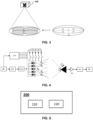
- FIG. 3 demonstrates one example of transmitter sectorization.
- the number of narrow beam light sources should be at least two.
- the apparatus comprises four narrow beam light sources L1-L4 and one wide beam light source, which are represented by five ellipses.
- Each of the light sources may be a LED, a laser, a laser diode, or a VCSEL.
- the FoVs of different light sources are illustrated in the figure, where the wide beam light source L5 has a FoV covers the combined FoVs of all the narrow beam light sources L1-L4. In this example, it assumes a uniform split of the four sectors, which should not be understood as a limitation to the scope of the invention.
- the FoVs of the multiple narrow beam light sources may be the same or different from each other. There may also be an overlap between the FoVs of two adjacent narrow beam light sources.
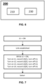
- FIG. 4 illustrates one possible system architecture of a sectorized transmitter and a remote receiver.
- the sectorized transmitter comprises a low-cost microcontroller CTR, a plurality of switches, such as single pole single throw (SPST) SPST switches, S1...S5 to control multiple light sources L1-L5.
- L5 has a wide beam angle or wide divergence angle ⁇ 5 and the other light sources L1-L4 have narrow beam angles or narrow divergence angles ⁇ 1 ⁇ ⁇ 4 , respectively.
- L1-L4 are configured to have sectorized coverage profile by transmitting in narrow beam angles directed to different orientations.
- the divergence angle ⁇ 5 of L5 covers the combined divergence angles ⁇ 1 ⁇ ⁇ 4 of L1-L4.
- the total beam angle of the sectorized transmitter is defined by ⁇ 5 .
- ⁇ 5 As an example, to achieve a total beam angle of ⁇ 50°, it may be an option to configure ⁇ 5 to be around ⁇ 50° and each one of ⁇ 1 ⁇ ⁇ 4 to be around ⁇ 12.5° pointing in different directions.
- ⁇ 1 ⁇ ⁇ 4 it may also be an option to have ⁇ 1 ⁇ ⁇ 4 being configured to be larger than ⁇ 12.5 ° allowing an overlap between two adjacent sectors.
- L1-L4 are of the same type and/or have the same beam angle.
- a hybrid configuration with different light sources may also be adopted for the narrow beam light sources.
- the disclosed method can still apply, as long as the test signals are not sent by more than one narrow beam light source simultaneously.
- the feedback signal is based on a received signal quality of a test signal sent by at most a single narrow beam light source.
- the overlapping of FoVs among narrow beam light sources will not introduce interference to each other during the beam selection procedure.
- the microcontroller CTR may control the switches S1-S5 for sending test signals via the wide beam light source L5 and the narrow beam light sources L1-L4 to a remote receiver. And then upon one or more feedbacks received from the remote device, the microcontroller CTR may select one narrow beam light source to establish a high-speed transmission link between the sectorized transmitter and the remote receiver.
- the one or more feedbacks are related to signal qualities of the one or more test signals received by the remote receiver.
- a signal quality may be represented by one of: a received signal strength, a signal to noise ratio (SNR), a power spectrum density (PSD), and a bit error rate (BER).
- the system may comprise a dedicated baseband module BB used to extract information received from the remote receiver.
- the dedicated baseband module BB may be used to demodulate signals for a front end used for either optical wireless communication or RF communication, or for both. It may also be possible that the microcontroller CTR is capable to demodulate the feedbacks received from the remote receiver. Then the dedicated baseband module BB is used for data communication, but not for the signaling control during the beam selection procedure. Depending on the system setup, the microcontroller CTR may be connected to the baseband module BB, as shown in Fig. 4 . It may also be possible that the microcontroller CTR is connected to the analog front end AFE directly.
- the receiver comprised in the apparatus is an OWC receiver, and the OWC receiver is configured not only to receive the one or more feedback signals from the remote device, but also to receive OWC data from the remote device for bi-directional data communication.
- the OWC receiver is a wide FoV receiver, such that the FoV of the OWC receiver is comparable to the FoV of the wide beam light source L5 of the apparatus 100.
- the receiver comprised in the apparatus is a radio receiver.
- the feedback signals are sent by the remote device over a radio frequency channel.
- FIG. 5 illustrates a basic block diagram of the remote device 200.
- the remote device 200 is an OWC transceiver, which comprises at least one light sensor 210 and one light source 220.
- the apparatus is also an OWC transceiver.
- the signaling exchange between the apparatus 100 and the remote device 200 is carried out via an OWC channel.
- the remote device 200 may be configured similar to the apparatus, such that it comprises more than one light source 220 and a single light sensor 210.
- the feedback signals are preferably be sent by the wide beam light source. It may also be possible that the remote device 200 is powered by mains power. And then the remote device may have both a sectorized OWC transmitting front end with more than one light source and a sectorized OWC receiving front end with more than one light sensor.
- FIG. 6 illustrates another example of the basic block diagram of the remote device 200.
- the remote device comprises at least one light sensor 210 for detecting the test signals sent by the apparatus 200 and a radio transmitter 230.
- the radio transmitter 230 is configured to send one or more feedback signals via a radio frequency channel to the apparatus 100 upon receipt of at least one of the test signals from the apparatus.
- the remote device 200 may be merely an OWC receiver to support a unidirectional OWC link from the apparatus 100 to the remote device 200.
- the remote device 200 may further comprise an OWC transmitter to carry out optical data communication, in which option a RF feedback link is used to assist the beam alignment procedure for establishing a bi-directional OWC link.
- a currently emitting narrow beam light source is turned off and a next narrow beam light source is turned on.
- the narrow beam light source contributing to the best signal quality is selected for establishing data communication with the remote device.
- the feedback signals received from the remote device is based on a received signal mixed with the test signals from the wide beam light source L5 and an individual narrow beam light source L1-L4.
- a first feedback signal is also provided by the remote device, which is dedicated to the contribution of L5.
- L5 is turned ON to establish a low speed signaling link, and the link quality as indicated in the feedback signal regarding L5 is recorded as LQ(i).
- an individual narrow beam light source is also turned on.
- narrow beam light source L1 is turned on and L2-L4 remain off state. Note that another order of the turning on the narrow beam light sources may also be possible, such that by taking a preference of using different narrow beam light sources into account.
- the link quality related to a combined contribution of L1 and L5 is recorded as LQ(i+1). When LQ(i+1) is better than LQ(i), in the additional step, L5 is also turned off.
- LQ(i+2) is better than LQ(i+1)
- LQ(i+1) indicates that L2 may be a better option as compared to L1
- the additional step to check the individual contribution of L2 is also carried out.
- the beam selection procedure loops through the combination of an individual narrow beam light source and the wide beam light source and carries out additional steps selectively to identify the performance of a certain narrow beam light source individually. Therefore, a more accurate decision can be made.
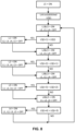
- FIG. 9 shows a flow chart of a method 500 an apparatus 100 for use in an OWC system.
- the method 500 comprises the apparatus 100: in step S501 turning, by a plurality of switches S1-S5, on or off a corresponding one out of a wide beam light source L5 and two or more narrow beam light sources L1-L4 individually; in step S502, emitting by each of the two or more narrow beam light sources L1-L4 in a different direction, wherein a combined field-of-view, FoV, of the narrow beam light sources L1-L4 is covered by a FoV of the wide beam light source L5; in step S503, receiving one or more feedback signals from a remote device 200; controlling, in step S504, the plurality of switches S1-S5 via a control signal; in step S505, updating the control signal based on the one or more feedback signals received by the receiver; in step S506, carrying out a beam selection procedure by sending test signals via the wide beam light source L5 and one or more narrow beam light sources L1-
- Executable code for a method according to the invention may be stored on computer/machine readable storage means.
- Examples of computer/machine readable storage means include non-volatile memory devices, optical storage medium/devices, solid-state media, integrated circuits, servers, etc.
- the computer program product comprises non-transitory program code means stored on a computer readable medium for performing a method according to the invention when said program product is executed on a computer.
Landscapes
- Engineering & Computer Science (AREA)
- Physics & Mathematics (AREA)
- Electromagnetism (AREA)
- Computer Networks & Wireless Communication (AREA)
- Signal Processing (AREA)
- Computing Systems (AREA)
- Optical Communication System (AREA)
Claims (14)
- Einrichtung (100) zur Verwendung in einem System für optische drahtlose Kommunikation, OWC-System, (300), die Einrichtung (100) umfassend:- eine Breitstrahllichtquelle (L5);- zwei oder mehr Schmalstrahllichtquellen (L1-L4), die jeweils konfiguriert sind, um in eine unterschiedliche Richtung zu strahlen, wobei ein kombiniertes Sichtfeld, FoV, der Schmalstrahllichtquellen (L1-L4) durch ein FoV der Breitstrahllichtquelle (L5) abgedeckt ist;- eine Vielzahl von Schaltern (S1-S5), die jeweils konfiguriert sind, um eine entsprechende eine aus den Breitstrahllichtquellen (L5) und den zwei oder mehr Schmalstrahllichtquellen (L1-L4) einzeln ein- oder auszuschalten;- einen Empfänger (RX), der konfiguriert ist, um ein oder mehrere Rückkopplungssignale von einer entfernten Vorrichtung (200) zu empfangen; und- eine Steuerung (CTR), die konfiguriert ist zum:o Steuern der Vielzahl von Schaltern (S1-S5) über ein Steuersignal;o Aktualisieren des Steuersignals basierend auf dem einem oder den mehreren Rückkopplungssignalen, die durch den Empfänger (RX) empfangen werden;o Durchführen eines Strahlauswahlvorgangs durch Senden von Testsignalen über die Breitstrahllichtquelle (L5) und eine oder mehrere Schmalstrahllichtquellen (L1-L4) an die entfernte Vorrichtung (200), um eine Auswahl einer aus den Schmalstrahllichtquellen (L1-L4) zum Herstellen einer Datenkommunikation mit der entfernten Vorrichtung (200) zu ermöglichen,dadurch gekennzeichnet, dass die Steuerung konfiguriert ist, um, während des Strahlauswahlvorgangs, das Steuersignal einzustellen auf:- Einschalten der Breitstrahllichtquelle (L5) und gleichzeitig,- Einschalten höchstens eine der Schmalstrahllichtquellen (L1-L4);und wobei die Breitstrahllichtquelle (L5) und der Empfänger konfiguriert sind, um eine langsame bidirektionale Signalverbindung mit der entfernten Vorrichtung (200) aufrechtzuerhalten, um den Strahlauswahlvorgang zu unterstützen.
- Einrichtung (100) nach Anspruch 1, wobei der Empfänger (RX) ein OWC-Empfänger ist und der OWC-Empfänger ferner konfiguriert ist, um Datenpakete von der entfernten Vorrichtung (200) für eine Datenkommunikation zu empfangen.
- Einrichtung (100) nach Anspruch 1, wobei der Empfänger (RX) ein Funkempfänger ist und das eine oder die mehreren Rückkopplungssignale durch den Funkempfänger über einen Hochfrequenzkanal empfangen werden.
- Einrichtung (100) nach einem der vorstehenden Ansprüche, wobei jede Schmalstrahllichtquelle eine größere Signalbandbreite als die Breitstrahllichtquelle (L5) unterstützt.
- Einrichtung (100) nach einem der vorstehenden Ansprüche, wobei das eine oder die mehreren Rückkopplungssignale mit einer Signalqualität eines Testsignals in Zusammenhang stehen, das durch die entfernte Vorrichtung (200) empfangen wird, und die Signalqualität mit mindestens einem in Zusammenhang steht von: einer empfangenen Signalstärke, einem Signal-Rausch-Verhältnis, einer Leistungszustandsdichte und einer Bitfehlerrate.
- Einrichtung (100) nach Anspruch 5, wobei die Steuerung konfiguriert ist, um das Steuersignal einzustellen, um während des Strahlauswahlvorgangs sequenziell jede eine aus den Schmalstrahllichtquellen (L1-L4) einzuschalten.
- Einrichtung (100) nach Anspruch 6, wobei die Steuerung (CTR) konfiguriert ist, um eine Schmalstrahllichtquelle basierend auf einem Vergleich von Signalqualitäten auszuwählen, die in Rückkopplungssignalen enthalten sind, die sequenziell entsprechend einem Zeitraum empfangen werden, in der eine einzelne Schmalstrahllichtquelle eingeschaltet ist.
- Einrichtung (100) nach Anspruch 5, wobei die Steuerung (CTR) konfiguriert ist, um eine Schmalstrahllichtquelle auszuwählen, wenn eine Signalqualität, die in einem Rückkopplungssignal enthalten ist, größer als ein vordefinierter Schwellenwert ist, und das Rückkopplungssignal in einem Zeitraum empfangen wird, in dem die entsprechende Schmalstrahllichtquelle eingeschaltet ist.
- Einrichtung (100) nach einem der vorstehenden Ansprüche, wobei die Steuerung (CTR) konfiguriert ist, um die Vielzahl von Schaltern (S1-S5) zu steuern, um nur eine ausgewählte Schmalstrahllichtquelle für die Datenkommunikation einzuschalten und alle anderen Lichtquellen nach dem Strahlauswahlvorgang auszuschalten.
- Einrichtung (100) nach einem der vorstehenden Ansprüche, wobei jede der Breitstrahllichtquelle (L5) und der zwei oder mehr Schmalstrahllichtquellen (L1-L4) mindestens eines umfassen von: einer LED, einem Laser und einem oberflächenemittierenden Diodenlaser (VCSEL).
- System (300) für optische drahtlose Kommunikation, OWC-System, umfassend:- Einrichtung (100) nach Anspruch 2; und- einen entfernten OWC-Sendeempfänger (200), umfassend:o mindestens einen Lichtsensor (210), der konfiguriert ist, um mindestens eines der Testsignale zu empfangen, die durch die Einrichtung (100) gesendet werden;o mindestens eine Lichtquelle (220), die konfiguriert ist, um nach einem Empfang von mindestens einem der Testsignale von der Einrichtung (100) durch den mindestens einen Lichtsensor ein oder mehrere Rückkopplungssignale an die Einrichtung (100) zu senden.
- System (300) für optische drahtlose Kommunikation, OWC-System, umfassend:- Einrichtung (100) nach Anspruch 3; und- einen entfernten OWC-Empfänger (200), umfassend:o mindestens einen Lichtsensor (210), der konfiguriert ist, um mindestens eines der Testsignale zu empfangen, die durch die Einrichtung (100) gesendet werden;o mindestens einen Funksender (230), der konfiguriert ist, um nach dem Empfang von mindestens einem der Testsignale von der Einrichtung (100) durch den mindestens einen Lichtsensor ein oder mehrere Rückkopplungssignale über einen Funkfrequenzkanal an die Einrichtung (100) zu senden.
- Verfahren (500) einer Einrichtung (100) zur Verwendung in einem System für optische drahtlose Kommunikation, OWC-System, (300), das Verfahren (500) umfassend die Schritte:- individuelles Ein- oder Ausschalten (S501), durch eine Vielzahl von Schaltern (S1-S5), einer entsprechenden einen aus einer Breitstrahllichtquelle (L5) und zwei oder mehr Schmalstrahllichtquellen (L1-L4);- Emittieren (S502) durch jede der zwei oder mehr Schmalstrahllichtquellen (L1-L4) in eine unterschiedliche Richtung, wobei ein kombiniertes Sichtfeld, FoV, der Schmalstrahllichtquellen (L1-L4) durch ein FoV der Breitstrahllichtquelle (L5) abgedeckt ist;- Empfangen (S503) eines oder mehrerer Rückkopplungssignale durch eine entfernte Vorrichtung (200) durch einen Empfänger;- Steuern (S504) der Vielzahl von Schaltern (S1-S5) über ein Steuersignal;- Aktualisieren (S505) des Steuersignals basierend auf dem einen oder den mehreren Rückkopplungssignalen, die durch den Empfänger empfangen werden;- Durchführen (S506) eines Strahlauswahlvorgangs durch Senden von Testsignalen über die Breitstrahllichtquelle (L5) und eine oder mehrere Schmalstrahllichtquellen (L1-L4) an die entfernte Vorrichtung (200) zum Auswählen einer aus den Schmalstrahllichtquellen (L1-L4), um die Datenkommunikation mit der entfernten Vorrichtung (200) herzustellen;- dadurch gekennzeichnet, dass das Verfahren ferner den Schritt des gleichzeitigen Einschaltens der Breitstrahllichtquelle (L5) und höchstens einer der Schmalstrahllichtquellen (L1-L4) während des Strahlauswahlvorgangs umfasst; und wobei die Breitstrahllichtquelle (L5) und der Empfänger eine langsame bidirektionale Signalverbindung mit der entfernten Vorrichtung (200) aufrechterhalten, um den Strahlauswahlvorgang zu unterstützen.
- Rechenprogramm, umfassend Codemittel, die, wenn das Programm durch eine Einrichtung (100) nach Anspruch 1 ausgeführt wird, umfassend Verarbeitungsmittel, die Verarbeitungsmittel veranlassen, das Verfahren nach Anspruch 13 vorzunehmen.
Applications Claiming Priority (2)
| Application Number | Priority Date | Filing Date | Title |
|---|---|---|---|
| EP21175291 | 2021-05-21 | ||
| PCT/EP2022/063155 WO2022243229A1 (en) | 2021-05-21 | 2022-05-16 | A sectorization technique for high-speed optical wireless communication |
Publications (2)
| Publication Number | Publication Date |
|---|---|
| EP4342104A1 EP4342104A1 (de) | 2024-03-27 |
| EP4342104B1 true EP4342104B1 (de) | 2025-07-09 |
Family
ID=76059752
Family Applications (1)
| Application Number | Title | Priority Date | Filing Date |
|---|---|---|---|
| EP22728262.1A Active EP4342104B1 (de) | 2021-05-21 | 2022-05-16 | Sektorisierungstechnik für optische drahtlose hochgeschwindigkeitskommunikation |
Country Status (4)
| Country | Link |
|---|---|
| US (1) | US12549253B2 (de) |
| EP (1) | EP4342104B1 (de) |
| CN (1) | CN117356048A (de) |
| WO (1) | WO2022243229A1 (de) |
Families Citing this family (1)
| Publication number | Priority date | Publication date | Assignee | Title |
|---|---|---|---|---|
| CN117856899A (zh) * | 2024-02-28 | 2024-04-09 | 广东电网有限责任公司广州供电局 | 一种配电房可见光通信方法、系统及通信设备 |
Family Cites Families (10)
| Publication number | Priority date | Publication date | Assignee | Title |
|---|---|---|---|---|
| US6606175B1 (en) | 1999-03-16 | 2003-08-12 | Sharp Laboratories Of America, Inc. | Multi-segment light-emitting diode |
| US20020131121A1 (en) * | 2001-03-13 | 2002-09-19 | Muthu Jeganathan | Transceiver, system, and method for free-space optical communication and tracking |
| US20040258415A1 (en) * | 2003-06-18 | 2004-12-23 | Boone Bradley G. | Techniques for secure free space laser communications |
| US8295706B2 (en) * | 2010-05-10 | 2012-10-23 | Exelis Inc. | Technique for simultaneously transmitting wide and narrow optical beacon signals |
| US9473229B2 (en) | 2012-10-05 | 2016-10-18 | Samsung Electronics Co., Ltd. | High-throughput beamforming MIMO receiver for millimeter wave communication and method |
| US9391368B2 (en) * | 2013-02-11 | 2016-07-12 | Intel Deutschland Gmbh | Radio communication devices and methods for controlling a radio communication device |
| US9438337B2 (en) * | 2014-05-31 | 2016-09-06 | Cisco Technology, Inc. | Control system for multi-beam free space optical endpoint |
| CN107026683B (zh) | 2017-03-23 | 2020-08-14 | 北京工业大学 | 一种基于空间分集自适应的mimo-fso系统 |
| US20190082520A1 (en) | 2017-06-29 | 2019-03-14 | Mohammad Noshad | Wide angle optical wireless transmitter including multiple narrow beam width light emitting diodes |
| CN118235344A (zh) * | 2021-11-11 | 2024-06-21 | 昕诺飞控股有限公司 | 用于光学无线通信系统的基于竞争的接入 |
-
2022
- 2022-05-16 EP EP22728262.1A patent/EP4342104B1/de active Active
- 2022-05-16 US US18/561,005 patent/US12549253B2/en active Active
- 2022-05-16 CN CN202280036751.1A patent/CN117356048A/zh active Pending
- 2022-05-16 WO PCT/EP2022/063155 patent/WO2022243229A1/en not_active Ceased
Also Published As
| Publication number | Publication date |
|---|---|
| CN117356048A (zh) | 2024-01-05 |
| WO2022243229A1 (en) | 2022-11-24 |
| US12549253B2 (en) | 2026-02-10 |
| EP4342104A1 (de) | 2024-03-27 |
| US20240259097A1 (en) | 2024-08-01 |
Similar Documents
| Publication | Publication Date | Title |
|---|---|---|
| US12294410B2 (en) | Trigger-based optical wireless communication system | |
| EP4218159B1 (de) | Verfahren und vorrichtung zur übergabesteuerung in einem optischen drahtloskommunikationsnetzwerk | |
| EP4154435B1 (de) | Verbindungsaufbau in einem drahtlosen mehrzellen-netzwerk | |
| US12192834B2 (en) | Secure handover in a LiFi network | |
| WO2022048845A1 (en) | A receiving system for high speed and large coverage optical wireless communication | |
| Beysens et al. | Exploiting blockage in VLC networks through user rotations | |
| EP4342104B1 (de) | Sektorisierungstechnik für optische drahtlose hochgeschwindigkeitskommunikation | |
| WO2022013146A1 (en) | A flexible and reliable wireless communication system | |
| EP4244998B1 (de) | Hybrider optischer sender für optische drahtlose hochgeschwindigkeitskommunikation | |
| US20240014900A1 (en) | Method and system for mobile docking with lifi | |
| CN116830483A (zh) | 用于在混合光学无线通信系统中交换数据的装置和方法 | |
| US20220256406A1 (en) | System and method for handovers in an optical wireless communication network | |
| CN113783619A (zh) | 一种基于融合可见光通信和可见光定位的优化方法 | |
| Abir et al. | SDN-enabled visible light communication system for next generation 6G networks | |
| Silva et al. | Visible Light Communication for Vehicular Networks: A Tutorial | |
| Yin | Heterogeneous Wireless and Visible Light Communication for the Internet of Things |
Legal Events
| Date | Code | Title | Description |
|---|---|---|---|
| STAA | Information on the status of an ep patent application or granted ep patent |
Free format text: STATUS: UNKNOWN |
|
| STAA | Information on the status of an ep patent application or granted ep patent |
Free format text: STATUS: THE INTERNATIONAL PUBLICATION HAS BEEN MADE |
|
| PUAI | Public reference made under article 153(3) epc to a published international application that has entered the european phase |
Free format text: ORIGINAL CODE: 0009012 |
|
| STAA | Information on the status of an ep patent application or granted ep patent |
Free format text: STATUS: REQUEST FOR EXAMINATION WAS MADE |
|
| 17P | Request for examination filed |
Effective date: 20231221 |
|
| AK | Designated contracting states |
Kind code of ref document: A1 Designated state(s): AL AT BE BG CH CY CZ DE DK EE ES FI FR GB GR HR HU IE IS IT LI LT LU LV MC MK MT NL NO PL PT RO RS SE SI SK SM TR |
|
| DAV | Request for validation of the european patent (deleted) | ||
| DAX | Request for extension of the european patent (deleted) | ||
| GRAP | Despatch of communication of intention to grant a patent |
Free format text: ORIGINAL CODE: EPIDOSNIGR1 |
|
| STAA | Information on the status of an ep patent application or granted ep patent |
Free format text: STATUS: GRANT OF PATENT IS INTENDED |
|
| INTG | Intention to grant announced |
Effective date: 20241216 |
|
| P01 | Opt-out of the competence of the unified patent court (upc) registered |
Free format text: CASE NUMBER: APP_9507/2025 Effective date: 20250226 |
|
| GRAS | Grant fee paid |
Free format text: ORIGINAL CODE: EPIDOSNIGR3 |
|
| GRAA | (expected) grant |
Free format text: ORIGINAL CODE: 0009210 |
|
| STAA | Information on the status of an ep patent application or granted ep patent |
Free format text: STATUS: THE PATENT HAS BEEN GRANTED |
|
| AK | Designated contracting states |
Kind code of ref document: B1 Designated state(s): AL AT BE BG CH CY CZ DE DK EE ES FI FR GB GR HR HU IE IS IT LI LT LU LV MC MK MT NL NO PL PT RO RS SE SI SK SM TR |
|
| REG | Reference to a national code |
Ref country code: GB Ref legal event code: FG4D |
|
| REG | Reference to a national code |
Ref country code: CH Ref legal event code: EP |
|
| REG | Reference to a national code |
Ref country code: IE Ref legal event code: FG4D |
|
| REG | Reference to a national code |
Ref country code: DE Ref legal event code: R096 Ref document number: 602022017329 Country of ref document: DE |
|
| REG | Reference to a national code |
Ref country code: NL Ref legal event code: MP Effective date: 20250709 |
|
| PG25 | Lapsed in a contracting state [announced via postgrant information from national office to epo] |
Ref country code: PT Free format text: LAPSE BECAUSE OF FAILURE TO SUBMIT A TRANSLATION OF THE DESCRIPTION OR TO PAY THE FEE WITHIN THE PRESCRIBED TIME-LIMIT Effective date: 20251110 |
|
| PG25 | Lapsed in a contracting state [announced via postgrant information from national office to epo] |
Ref country code: NL Free format text: LAPSE BECAUSE OF FAILURE TO SUBMIT A TRANSLATION OF THE DESCRIPTION OR TO PAY THE FEE WITHIN THE PRESCRIBED TIME-LIMIT Effective date: 20250709 |
|
| REG | Reference to a national code |
Ref country code: AT Ref legal event code: MK05 Ref document number: 1812863 Country of ref document: AT Kind code of ref document: T Effective date: 20250709 |
|
| PG25 | Lapsed in a contracting state [announced via postgrant information from national office to epo] |
Ref country code: IS Free format text: LAPSE BECAUSE OF FAILURE TO SUBMIT A TRANSLATION OF THE DESCRIPTION OR TO PAY THE FEE WITHIN THE PRESCRIBED TIME-LIMIT Effective date: 20251109 |
|
| PG25 | Lapsed in a contracting state [announced via postgrant information from national office to epo] |
Ref country code: NO Free format text: LAPSE BECAUSE OF FAILURE TO SUBMIT A TRANSLATION OF THE DESCRIPTION OR TO PAY THE FEE WITHIN THE PRESCRIBED TIME-LIMIT Effective date: 20251009 |
|
| REG | Reference to a national code |
Ref country code: LT Ref legal event code: MG9D |
|
| PG25 | Lapsed in a contracting state [announced via postgrant information from national office to epo] |
Ref country code: AT Free format text: LAPSE BECAUSE OF FAILURE TO SUBMIT A TRANSLATION OF THE DESCRIPTION OR TO PAY THE FEE WITHIN THE PRESCRIBED TIME-LIMIT Effective date: 20250709 |
|
| PG25 | Lapsed in a contracting state [announced via postgrant information from national office to epo] |
Ref country code: FI Free format text: LAPSE BECAUSE OF FAILURE TO SUBMIT A TRANSLATION OF THE DESCRIPTION OR TO PAY THE FEE WITHIN THE PRESCRIBED TIME-LIMIT Effective date: 20250709 |
|
| PG25 | Lapsed in a contracting state [announced via postgrant information from national office to epo] |
Ref country code: HR Free format text: LAPSE BECAUSE OF FAILURE TO SUBMIT A TRANSLATION OF THE DESCRIPTION OR TO PAY THE FEE WITHIN THE PRESCRIBED TIME-LIMIT Effective date: 20250709 |
|
| PG25 | Lapsed in a contracting state [announced via postgrant information from national office to epo] |
Ref country code: GR Free format text: LAPSE BECAUSE OF FAILURE TO SUBMIT A TRANSLATION OF THE DESCRIPTION OR TO PAY THE FEE WITHIN THE PRESCRIBED TIME-LIMIT Effective date: 20251010 |
|
| PG25 | Lapsed in a contracting state [announced via postgrant information from national office to epo] |
Ref country code: SE Free format text: LAPSE BECAUSE OF FAILURE TO SUBMIT A TRANSLATION OF THE DESCRIPTION OR TO PAY THE FEE WITHIN THE PRESCRIBED TIME-LIMIT Effective date: 20250709 |
|
| PG25 | Lapsed in a contracting state [announced via postgrant information from national office to epo] |
Ref country code: LV Free format text: LAPSE BECAUSE OF FAILURE TO SUBMIT A TRANSLATION OF THE DESCRIPTION OR TO PAY THE FEE WITHIN THE PRESCRIBED TIME-LIMIT Effective date: 20250709 |
|
| PG25 | Lapsed in a contracting state [announced via postgrant information from national office to epo] |
Ref country code: PL Free format text: LAPSE BECAUSE OF FAILURE TO SUBMIT A TRANSLATION OF THE DESCRIPTION OR TO PAY THE FEE WITHIN THE PRESCRIBED TIME-LIMIT Effective date: 20250709 Ref country code: BG Free format text: LAPSE BECAUSE OF FAILURE TO SUBMIT A TRANSLATION OF THE DESCRIPTION OR TO PAY THE FEE WITHIN THE PRESCRIBED TIME-LIMIT Effective date: 20250709 |
|
| PG25 | Lapsed in a contracting state [announced via postgrant information from national office to epo] |
Ref country code: RS Free format text: LAPSE BECAUSE OF FAILURE TO SUBMIT A TRANSLATION OF THE DESCRIPTION OR TO PAY THE FEE WITHIN THE PRESCRIBED TIME-LIMIT Effective date: 20251009 |
|
| PG25 | Lapsed in a contracting state [announced via postgrant information from national office to epo] |
Ref country code: ES Free format text: LAPSE BECAUSE OF FAILURE TO SUBMIT A TRANSLATION OF THE DESCRIPTION OR TO PAY THE FEE WITHIN THE PRESCRIBED TIME-LIMIT Effective date: 20250709 |
|
| PG25 | Lapsed in a contracting state [announced via postgrant information from national office to epo] |
Ref country code: SM Free format text: LAPSE BECAUSE OF FAILURE TO SUBMIT A TRANSLATION OF THE DESCRIPTION OR TO PAY THE FEE WITHIN THE PRESCRIBED TIME-LIMIT Effective date: 20250709 |
|
| PGFP | Annual fee paid to national office [announced via postgrant information from national office to epo] |
Ref country code: GB Payment date: 20260304 Year of fee payment: 5 |
|
| PG25 | Lapsed in a contracting state [announced via postgrant information from national office to epo] |
Ref country code: DK Free format text: LAPSE BECAUSE OF FAILURE TO SUBMIT A TRANSLATION OF THE DESCRIPTION OR TO PAY THE FEE WITHIN THE PRESCRIBED TIME-LIMIT Effective date: 20250709 |
|
| PG25 | Lapsed in a contracting state [announced via postgrant information from national office to epo] |
Ref country code: IT Free format text: LAPSE BECAUSE OF FAILURE TO SUBMIT A TRANSLATION OF THE DESCRIPTION OR TO PAY THE FEE WITHIN THE PRESCRIBED TIME-LIMIT Effective date: 20250709 |