EP4340998B1 - Mantle retaining system and method for a gyratory crusher - Google Patents
Mantle retaining system and method for a gyratory crusher Download PDFInfo
- Publication number
- EP4340998B1 EP4340998B1 EP22729957.5A EP22729957A EP4340998B1 EP 4340998 B1 EP4340998 B1 EP 4340998B1 EP 22729957 A EP22729957 A EP 22729957A EP 4340998 B1 EP4340998 B1 EP 4340998B1
- Authority
- EP
- European Patent Office
- Prior art keywords
- headnut
- bores
- series
- cylinders
- mantle
- Prior art date
- Legal status (The legal status is an assumption and is not a legal conclusion. Google has not performed a legal analysis and makes no representation as to the accuracy of the status listed.)
- Active
Links
Images




Classifications
-
- B—PERFORMING OPERATIONS; TRANSPORTING
- B02—CRUSHING, PULVERISING, OR DISINTEGRATING; PREPARATORY TREATMENT OF GRAIN FOR MILLING
- B02C—CRUSHING, PULVERISING, OR DISINTEGRATING IN GENERAL; MILLING GRAIN
- B02C2/00—Crushing or disintegrating by gyratory or cone crushers
- B02C2/02—Crushing or disintegrating by gyratory or cone crushers eccentrically moved
- B02C2/04—Crushing or disintegrating by gyratory or cone crushers eccentrically moved with vertical axis
-
- B—PERFORMING OPERATIONS; TRANSPORTING
- B02—CRUSHING, PULVERISING, OR DISINTEGRATING; PREPARATORY TREATMENT OF GRAIN FOR MILLING
- B02C—CRUSHING, PULVERISING, OR DISINTEGRATING IN GENERAL; MILLING GRAIN
- B02C2/00—Crushing or disintegrating by gyratory or cone crushers
- B02C2/005—Lining
-
- B—PERFORMING OPERATIONS; TRANSPORTING
- B02—CRUSHING, PULVERISING, OR DISINTEGRATING; PREPARATORY TREATMENT OF GRAIN FOR MILLING
- B02C—CRUSHING, PULVERISING, OR DISINTEGRATING IN GENERAL; MILLING GRAIN
- B02C23/00—Auxiliary methods or auxiliary devices or accessories specially adapted for crushing or disintegrating not provided for in preceding groups or not specially adapted to apparatus covered by a single preceding group
-
- F—MECHANICAL ENGINEERING; LIGHTING; HEATING; WEAPONS; BLASTING
- F16—ENGINEERING ELEMENTS AND UNITS; GENERAL MEASURES FOR PRODUCING AND MAINTAINING EFFECTIVE FUNCTIONING OF MACHINES OR INSTALLATIONS; THERMAL INSULATION IN GENERAL
- F16B—DEVICES FOR FASTENING OR SECURING CONSTRUCTIONAL ELEMENTS OR MACHINE PARTS TOGETHER, e.g. NAILS, BOLTS, CIRCLIPS, CLAMPS, CLIPS OR WEDGES; JOINTS OR JOINTING
- F16B39/00—Locking of screws, bolts or nuts
- F16B39/02—Locking of screws, bolts or nuts in which the locking takes place after screwing down
Definitions
- the disclosed system generally relates to a gyratory crusher as used in the mining industry. More specifically, the present disclosure relates to a retainer assembly that includes a headnut that can be used to secure a mantle to a mainshaft of a gyratory crusher.
- Gyratory type crushers are used in the mining industry for reducing ore to a predetermined size for further processing. These style of crushers have taken over most large hard-ore and mineral-crushing applications which has made them an integral part of the mining industry.
- a gyratory crusher includes a stationary conical bowl which opens upwardly and has an annular opening in its top to receive feed material.
- a conical pestle, opening downwardly, is disposed within the center of the bowl.
- the pestle is eccentrically oscillated for gyratory crushing movement with respect to the bowl.
- the conical angles of the pestle and bowl are such that the width of the passage decreases towards the bottom of the working faces and may be adjusted to define the smallest diameter of product ore.
- each bowl and pestle includes a liner assembly replaceably mounted on the working faces, these liners define the actual crushing surface.
- the liner on the pestle is fitted around the outside of a mainshaft.
- the mantle provides a replaceable wearing surface.
- a threaded section on the mainshaft (or a threaded bearing sleeve fit over the mainshaft) is provided for receiving a headnut.
- the headnut forces the mantle downward onto the tapered portion of the mainshaft, and is forceably tightened against the top of the mantle. Tightening of the headnut prevents relative rotational movement between the headnut and the mantle.
- the crusher is put into operation, the large forces involved in crushing stone cause a differential rotational movement between the mainshaft and the mantle.
- the headnut on the threaded section of the mainshaft is also caused to rotate relative to the shaft, in a direction which acts to further tighten the headnut onto the mantle.
- the rotational movement of the headnut relative to the mainshaft causes a large force to be transmitted in a downward direction from the headnut so as to forceably wedge the mantle onto the tapered portion of the mainshaft, securing the mantle to the mainshaft.
- the force also causes the bottom surface of the headnut to be pressed tightly against the top surface of the mantle such that the frictional force between the headnut and the mantle is quite large.
- the frictional force between the headnut and the mantle makes it difficult to loosen the headnut by turning.
- the crushing surface of the mantle is subjected to a hammering action by repeated impact of the rock or other material being crushed. This hammering action causes the working surface of the mantle to expand by cold working.
- the expansion of the mantle works to increase the fictional force between the headnut and the mantle.
- the cumulative effect of the tremendous frictional force between the headnut and the mantle is that it becomes impossible to loosen the headnut by turning it.
- a solution to this problem in the prior art is to provide a burning ring between the mantle and the headnut.
- the burning ring is adapted so as to engage to the upper surface of the mantle and the lower surface of the headnut.
- the burning ring is cut with a cutting torch, relieving the frictional forces bearing on the headnut.
- the threaded portion of the headnut may then be unscrewed from the shaft and the mantle can be removed.
- WO 2020/073077 discloses a hydraulic mantle system for a gyratory rock crusher which includes a main shaft, an annular nut, an annular hydraulic piston and an annular mantle.
- the main shaft has a flange and external threads adjacent the flange.
- the annular nut body has side surfaces and internal threads that are threaded onto the external threads of the main shaft.
- the annular hydraulic piston has side surfaces that slidingly engage the side surfaces of the annular nut body.
- the annular mantle has an upper neck portion and a lower edge portion.
- the main shaft extends through the upper neck portion. The upper neck portion of the annular mantle is compressed between the flange of the main shaft and the annular hydraulic piston.
- the headnut is typically used to forcibly secure the mantle to the crushing head assembly by applying a large downward force on the top of the mantle.
- the headnut includes an internally threaded surface that engages an externally threaded surface on the mainshaft or a bearing sleeve supported on the mainshaft.
- downward force is applied to the mantle by screwing down the internally threaded headnut on the mating threads of the externally threaded mainshaft bearing sleeve.
- the turning effort is typically applied by a special wrench having a protruding arm.
- the large amount of turning effort that is needed to tighten down the headnut often requires the use of difficult mechanical operations to create the sufficient locking force to adequately secure the mantle on the mainshaft.
- the inventors of the present disclosure identified the problems associated with the installation of the headnut and the difficult mechanical operation to provide the required holding force on the top edge of the mantle. As a result, the retainer assembly of the present disclosure was developed to solve the problems identified by the inventors.
- the present disclosure relates to a method and system for securing a mantle to a mainshaft of a gyratory crusher. More specifically, the present disclosure relates to a retainer assembly that improves the ease of connection between the mantle and mainshaft of a gyratory crusher.
- the retainer assembly of the present disclosure includes a headnut having a body defined by a first face surface and a second face surface.
- the headnut is an annular member that includes a series of threads designed to be received by a mating series of threads on a bearing sleeve installed on the mainshaft.
- the headnut further includes a first series of bores and a second series of bores.
- a burn ring is positioned below the headnut and is initially attached to the headnut by a series of connectors.
- the series of connectors extend through the first series of bores and are received in corresponding bores formed in the burn ring.
- a plurality of jacking bolts are received in the second series of bores formed in the headnut.
- Each of the jacking bolts are threaded into one of the bores of the second series of bores.
- the jacking bolts do not extend past the second face surface of the headnut.
- the lower end of the jacking bolt extends past the second face surface of the headnut.
- the cylinder body includes threads formed along the outer surface of the cylinder body.
- the threads formed on the cylinder body allow the hydraulic cylinder to be securely received within one of the second series of bores formed in the headnut.
- the series of connectors used to attach the headnut to the burn ring Prior to being received in the second series of bores, the series of connectors used to attach the headnut to the burn ring must first be removed. Thus, the headnut will be disconnected from the burn ring, other than through friction forces created by the dowel pins, before the hydraulic cylinders can be installed.
- the pressurized hydraulic fluid can be supplied to the hydraulic cylinders.
- the pressurized hydraulic fluid causes the cylinder rod and end effector to extend away from the cylinder body and move into contact with the top face surface of the burn ring.
- the continued movement of the end effectors causes the burn ring to be pressed into contact with the mantle and the headnut to move upward. This movement creates a gap between the burn ring and the headnut while also creating a locking force between the threads of the headnut and the threads of the bearing sleeve positioned on the mainshaft.
- the plurality of jacking bolts are rotated until the end of the jacking bolt contacts the burn ring.
- one or more shims can be inserted into the gap.
- the shims are each designed with cutouts that allow the shims to be inserted when the jacking bolts are extended and the hydraulic cylinders are still pressurized.
- the supply of pressurized hydraulic fluid can be removed, which causes the end effectors to retract.
- the jacking bolts and shims maintain the gap and the locking force after removal of the pressurized hydraulic fluid.
- the cutouts formed in the shims also allow for expansion of the shims during pressure such that the material of shim can expand and fill a portion of the cutouts.
- the plurality of hydraulic cylinders can be removed from the headnut.
- a headnut cover can then be installed over the headnut to protect the headnut and burn ring during operation of the gyratory crusher.
- the headnut cover is installed using a series of connectors that can be removed to allow removal of the headnut cover when the mantle needs to be removed and replaced.
- Figs. 1 and 3 generally illustrate several of the components of the retainer assembly constructed in accordance with the present disclosure.
- the illustrated components of the retainer assembly 10 are designed to be received along a bearing sleeve 12 that is positioned to surround a main shaft 14 of a gyratory crusher.
- the mainshaft 14 receives and supports a mantle 16 that is fitted around the outside of the mainshaft 14.
- the mantle 16 provides a replaceable wearing surface that needs to be replaced upon wear.
- the mantle 16 is held in place along the mainshaft 14 through use of the retainer assembly 10.
- the retainer assembly 10 includes a headnut 18 and a burn ring 20.
- the headnut 18 is a generally annular member formed from a durable metal material that includes a series of internal threads 22 formed along an annular inner surface 24.
- the internal threads 22 are designed to threadedly engage a series of external threads 26 formed on the lower end of the bearing sleeve 12.
- the retainer assembly 10 contacts a top edge 28 of the mantle 16 to hold the mantle 16 in place along the mainshaft.
- the mainshaft 14 includes a lifting lug 30 along the top end that provides a point of attachment for removing the entire mainshaft.
- the headnut 18 includes a main body 31 that extends between a first, top face surface 32 and a second, bottom face surface 34.
- the annular main body 31 that extends between the top face surface 32 and the bottom face surface 34 further defines the inner surface 24 that includes the threads 22.
- the headnut 18 includes a first series of bores 36 that each extend through the body from the first face surface 32 to the second face surface 34.
- the first series of bores 36 includes a total of four bores although other numbers are possible.
- the headnut 18 also includes a second series of bores 38 that also extend through the body from the first face surface 32 to the second face surface 34.
- the second series of bores 38 eight bores although other numbers are possible
- each of the second series of bores 38 are designed to receive one of a plurality of jacking bolts 40.
- Each of the jacking bolts 40 includes an externally threaded main body that extends between a head 42 and a contact end 44.
- Each of the second series of bores 38 includes a threaded inner surface that is designed to threadedly receive and engage the outer surface of one of the jacking bolts 40.
- the first series of bores 36 are designed to initially receive one of a plurality of connectors 46 that include an externally threaded outer shaft that extends between a head 48 and a lower end 50.
- a washer 52 is included as part of the connector 46 to prevent the head 48 from entering into the respective bore 36.
- the retainer assembly 10 includes the burn ring 20.
- the retainer assembly 10 could be constructed in some embodiments in which the burn ring 20 is eliminated.
- the top edge of the mantle would be formed from a stronger material and would replace the function of the burn ring as discussed below.
- the thickness of the burn ring 20 could be greatly reduced and the burn ring 20 could be formed from a stronger material such that a reduced thickness burn ring could carry out the functions set forth below.
- the burn ring 20 includes a first face surface 54 and a second face surface 56 that define the thickness of the annular body. As illustrated in Fig.
- the burn ring 20 includes a plurality of dowel pins 58 that are each received within one of a plurality of dowel pin bores 60, which are best shown in Fig. 2A .
- Each of the dowel pin bores 60 is sized to receive a first end 62 of the dowel pin 58.
- the upper end of the dowel pin bore 60 defines a support shoulder 64 that allows the dowel pin 58 to securely seat within the top end of the dowel pin bore 60.
- the dowel pin 58 is designed to be pressed into place in the burn ring 20 as shown in Fig. 2A .
- the dowel pins 58 could be welded in place from underneath or a combination of welding and friction could be used to hold the dowel pins 58 in place.
- the outer diameter of the dowel pin 58 is designed to be received within a receiving portion 66 that is formed as part of a cover member bore 68 that also extends between the first face 32 and the second face surface 34 of the headnut 18.
- each of the connectors 46 includes a head 48 and an externally threaded shaft 49.
- the lower end of the externally threaded shaft 49 is threadedly received within one of a plurality of attachment bores 70 that extend through the burn ring 20 from the first face surface 54 to the second face surface 56.
- the washer 52 is positioned below the head 48 to hold the head of the connector 46 above the inner diameter of the first series of bores 36.
- each of the individual jacking bolts 40 can be threadedly inserted into the second series of bores 38.
- Each of the jacking bolts 40 includes a recessed engagement portion 72 that extends into the body of the jacking bolt 40 from the top head portion 42.
- the main body of the jacking bolt 40 includes a series of external threads that engage a series of internal threads formed within each of the second series of bores 38.
- the length of the jacking bolt 40 is selected such that the contact end 44 is slightly spaced from the contact pads 74 that are slightly recessed from the first face surface 54 of the burn ring 20. In this manner, the jacking bolt 40 is entirely received within one of the second series of bores 38 during the initial installation process and does not exert any force on the burn ring 20.
- a series of lifting bolts 76 can be installed on the first face surface of the headnut 18.
- the lifting bolts 76 provide a point of attachment for lifting the combination of the headnut 18 and burn ring 20.
- Fig. 3 when the retainer assembly 10 is being lifted, the entire retainer assembly 10 can be lowered until the threaded portion of the headnut 18 contacts the external threads 26 formed on the bearing sleeve 12.
- Fig. 4 illustrates the initial contact between the threads 26 formed on the bearing sleeve 12 and the threads 22 formed along the inner surface 24 of the headnut 18.
- the combination of the headnut 18 and the burn ring 20 can be rotated using hand tools to cause the headnut 18 and burn ring 20 to move in a downward direction as illustrated by arrow 78.
- the rotation of the retainer assembly 10 can continue until the second face surface 56 of the burn ring comes into contact with the top edge 28 of the mantle 16. This interaction is best shown in Fig. 6 .
- the combination of the headnut and burn ring are threaded into place utilizing only a relatively small amount of force, such as by hand or by using a hand operated tool.
- Fig. 5 shows this initial positioning of the retainer assembly along the mainshaft 14. In this position, the retainer assembly lightly holds the mantle 16 in place. In this configuration, the connectors 46 are still used to connect the headnut 18 to the burn ring 20.
- each of the individual connectors 46 can be removed and a hydraulic kit 80 can be installed to perform the next step in the attachment process for securing the mantle 16 to the mainshaft.
- the hydraulic kit 80 is part of the entire retainer assembly and is used during the installation process as will be described. Although a hydraulic kit 80 is shown, other pressurized fluids or gases could be used in place of hydraulic fluid.
- the hydraulic kit 80 includes a plurality of individual hydraulic cylinders 82 that are each connected to each other through a fluid line 84.
- the hydraulic fluid line 84 provides a fluid connection for hydraulic fluid to pass between each of the individual cylinders 82.
- the end hydraulic cylinder 82 is connected to a supply of pressurized hydraulic fluid 86 through a supply line 88.
- the supply line 88 is connected to the supply of hydraulic fluid 86, the pressurized hydraulic fluid can flow between each of the individual hydraulic cylinders 82 in a well-known manner.
- the supply of hydraulic fluid 86 can be any type of hydraulic fluid supply that provides pressurized fluid at a desired fluid pressure.
- a hand pump is shown in the embodiment of Fig.
- pressurized hydraulic fluid could be connected to the plurality of cylinders to provide the required driving force to move the cylinder rod and internal piston.
- the supply of pressurized fluid could be pressurized air or other gas and the cylinders could be gas or air actuated cylinders.
- each of the individual hydraulic cylinders 82 includes a main cylinder body 90.
- the cylinder body 90 includes a series of external threads 92.
- the external threads 92 on the cylinder body 90 are configured to threadedly engage the internal threads formed along the inner surface of each of the first series of bores 36. In this manner, the hydraulic cylinders 82 can be threadedly received within the plurality of first series of bores 36.
- each of the hydraulic cylinders 82 includes an end effector 94 that is attached to a cylinder rod 96.
- the cylinder rod 96 is designed to be extended and retracted from within the cylinder body 90 upon application of pressurized hydraulic fluid to the hydraulic cylinder 82.
- the end effector 94 is shown in Fig. 9 in a retracted position in which the end effector 94 is slightly spaced from the first face surface 54 of the burn ring 20. Thus, in the non-pressurized condition, the end effector 94 does not exert any force on the burn ring 20.
- hydraulic fluid is applied to each of the individual hydraulic cylinders 82 as best shown in Fig. 12 .
- the cylinder rod 96 extends from the cylinder body 90 such that the end effector 94 contacts the first face surface 54 of the burn ring 20. Since the end effector 94 is moved under the pressure created by the supply of hydraulic fluid, the downward movement of the end effector 94 creates a corresponding upward movement of the headnut 18 away from the burn ring 20.
- the upward movement of the headnut 18 creates a physical interaction between the threaded portion of the headnut 18 and the threaded portion of the bearing sleeve 12.
- the physical interaction between the threaded portions of the headnut 18 and the bearing sleeve 12 creates a locking force on the burn ring 20 and thus the mantle 16.
- the gap 98 created can have range of sizes. In the embodiment illustrated, the gap 98 has a dimension of approximately 3.2 millimeters, although other sizes for the gap 98 are certainly contemplated as being within the scope of the present disclosure.
- each of the individual jacking bolts 40 is rotated within the respective bore to cause the contact end 44 of the jacking bolt 40 to contact the first surface 54 of the burn ring 20 as illustrated in Fig. 13 . Since each of the jacking bolts 40 is threaded into one of the second series of bores 38, the plurality of jacking bolts 40 can be used to maintain the gap 98 even when the individual hydraulic cylinders 82 are depressurized.
- one or more individual shims 100 can be inserted into the gap 98 to maintain the gap during operation of the gyratory crusher.
- the shims 100 are formed as separate segments that can be combined to create either an entire annular ring or portions of an annular ring. It is contemplated that multiple numbers of shims 100 could be utilized to help maintain the size of the gap between the headnut and the burn ring. In the embodiment shown in Fig.
- the individual shims include a series of cutouts 102 that are sized to receive the contact end of each of the jacking bolts 40 and the dowel pins.
- the shims 100 can be inserted as shown in Fig. 13 while the jacking bolts 40 maintain the size of the gap 98 and the dowel pins join and align the headnut and the burn ring.
- the cutouts 102 can also allow the shim 100 to be inserted while the hydraulic cylinders are pressurized and the dowel pins are installed, as shown in Fig. 12 .
- the hydraulic fluid applied to each of the individual hydraulic cylinders can be removed.
- the combination of the jacking bolts 40 and shims 100 maintain the gap 98 and also maintain the physical interaction between the threaded portions of the headnut 18 and the threaded portion of the bearing sleeve.
- the threaded bodies of each of the cylinders 82 can be rotated to remove the hydraulic cylinders 82 from the headnut 18.
- Fig. 14 illustrates the installed headnut and burn ring after the removal of the hydraulic cylinders as compared to the embodiment shown in Fig. 10 .
- a headnut cover 104 can be installed over the combination of the headnut 18 and the burn ring 20.
- the headnut cover 104 is designed to cover the headnut 18 during operation of the gyratory crusher to reduce the damage to the headnut 18.
- the headnut cover 104 is an annular member that includes a top face surface 106 that includes a plurality of bores 108 that are each designed to receive threaded connector 110.
- Each threaded connector 110 includes a threaded shaft 112 and a head 114, as illustrated in Fig. 15 .
- the headnut cover 104 includes a plurality of lifting lugs 116 that provide a point of attachment for lifting the headnut cover 104 and installing it over the headnut 18.
- the headnut cover 104 includes a top wall 118 and a depending side wall 120.
- the depending side wall 120 is connected to the top wall 118 along the radial outer edge 122.
- the side wall 120 is designed to have an inner circumference that is designed to fit over the outer surface 124 of the headnut 18.
- the bores 108 extending into the top face surface 106 are each designed to include an internal shoulder 126 that is designed to receive the head 114 of one of the connectors 110.
- Fig. 17 illustrates the mounting of the headnut cover 104 onto the combination of the headnut 18 and the burn ring 20. In this configuration, the threaded shaft of the connector 110 is received within the internal threaded portion of one of the cover member bores 68. In this manner, headnut cover 104 can be securely attached to the headnut as best illustrated in Figs. 16 and 17 .
- headnut cover 104 is first removed from the headnut 18 by removing the series of connectors 110. Once the headnut cover 104 is removed, the burn ring 20 can be cut using a torch, which removes the tension on the headnut 18. The headnut 18 can then be rotated away from the mantle 16 and the mantle removed from the mainshaft.
- the plurality of hydraulic cylinders 82 could be reinstalled into the first series of bores in the headnut.
- the pressurized hydraulic fluid can again be applied to the hydraulic cylinders 82 to help loosen the connection between the headnut and the mainshaft.
- the jacking bolts could be retracted combination of the headnut and burn ring could be removed, which would allow for reuse of the burn ring.
Landscapes
- Engineering & Computer Science (AREA)
- Mechanical Engineering (AREA)
- Food Science & Technology (AREA)
- General Engineering & Computer Science (AREA)
- Crushing And Grinding (AREA)
Description
- The disclosed system generally relates to a gyratory crusher as used in the mining industry. More specifically, the present disclosure relates to a retainer assembly that includes a headnut that can be used to secure a mantle to a mainshaft of a gyratory crusher.
- Gyratory type crushers are used in the mining industry for reducing ore to a predetermined size for further processing. These style of crushers have taken over most large hard-ore and mineral-crushing applications which has made them an integral part of the mining industry. Typically, a gyratory crusher includes a stationary conical bowl which opens upwardly and has an annular opening in its top to receive feed material. A conical pestle, opening downwardly, is disposed within the center of the bowl. The pestle is eccentrically oscillated for gyratory crushing movement with respect to the bowl. The conical angles of the pestle and bowl are such that the width of the passage decreases towards the bottom of the working faces and may be adjusted to define the smallest diameter of product ore. The oscillatory motion causes impact with the pestle and bowl, as a piece of ore is caught between the working faces of the bowl and pestle. Furthermore, each bowl and pestle includes a liner assembly replaceably mounted on the working faces, these liners define the actual crushing surface.
- The liner on the pestle, called a mantle, is fitted around the outside of a mainshaft. The mantle provides a replaceable wearing surface. A threaded section on the mainshaft (or a threaded bearing sleeve fit over the mainshaft) is provided for receiving a headnut. The headnut forces the mantle downward onto the tapered portion of the mainshaft, and is forceably tightened against the top of the mantle. Tightening of the headnut prevents relative rotational movement between the headnut and the mantle. When the crusher is put into operation, the large forces involved in crushing stone cause a differential rotational movement between the mainshaft and the mantle. The headnut on the threaded section of the mainshaft is also caused to rotate relative to the shaft, in a direction which acts to further tighten the headnut onto the mantle. Thus, the rotational movement of the headnut relative to the mainshaft causes a large force to be transmitted in a downward direction from the headnut so as to forceably wedge the mantle onto the tapered portion of the mainshaft, securing the mantle to the mainshaft. The force also causes the bottom surface of the headnut to be pressed tightly against the top surface of the mantle such that the frictional force between the headnut and the mantle is quite large.
- The frictional force between the headnut and the mantle makes it difficult to loosen the headnut by turning. Additionally, during operation of the crusher, the crushing surface of the mantle is subjected to a hammering action by repeated impact of the rock or other material being crushed. This hammering action causes the working surface of the mantle to expand by cold working. The expansion of the mantle works to increase the fictional force between the headnut and the mantle. The cumulative effect of the tremendous frictional force between the headnut and the mantle is that it becomes impossible to loosen the headnut by turning it.
- It is, however, necessary to remove the headnut when the mantle become worn and needs replacing. Since it is not practical to loosen the headnut by turning, it must be cut from the threaded section of the mainshaft. Removing the headnut in this manner damages the headnut beyond repair so that it cannot be used again. The threaded section of the mainshaft (or bearing sleeve) is also easily damaged when removing the headnut in this fashion, such that the threaded mainshaft or bearing sleeve must be repaired, or possibly replaced.
- A solution to this problem in the prior art is to provide a burning ring between the mantle and the headnut. The burning ring is adapted so as to engage to the upper surface of the mantle and the lower surface of the headnut. When the mantle is being replaced, the burning ring is cut with a cutting torch, relieving the frictional forces bearing on the headnut. The threaded portion of the headnut may then be unscrewed from the shaft and the mantle can be removed.
- As an example of the prior art,
WO 2020/073077 discloses a hydraulic mantle system for a gyratory rock crusher which includes a main shaft, an annular nut, an annular hydraulic piston and an annular mantle. The main shaft has a flange and external threads adjacent the flange. The annular nut body has side surfaces and internal threads that are threaded onto the external threads of the main shaft. The annular hydraulic piston has side surfaces that slidingly engage the side surfaces of the annular nut body. The annular mantle has an upper neck portion and a lower edge portion. The main shaft extends through the upper neck portion. The upper neck portion of the annular mantle is compressed between the flange of the main shaft and the annular hydraulic piston. - Installation problems often arise because the headnut assembly must be tightened into contact with the mantle to prevent excess "play" between the components. The headnut is typically used to forcibly secure the mantle to the crushing head assembly by applying a large downward force on the top of the mantle. The headnut includes an internally threaded surface that engages an externally threaded surface on the mainshaft or a bearing sleeve supported on the mainshaft. In conventional gyratory crushers, downward force is applied to the mantle by screwing down the internally threaded headnut on the mating threads of the externally threaded mainshaft bearing sleeve. The turning effort is typically applied by a special wrench having a protruding arm. The large amount of turning effort that is needed to tighten down the headnut often requires the use of difficult mechanical operations to create the sufficient locking force to adequately secure the mantle on the mainshaft.
- The inventors of the present disclosure identified the problems associated with the installation of the headnut and the difficult mechanical operation to provide the required holding force on the top edge of the mantle. As a result, the retainer assembly of the present disclosure was developed to solve the problems identified by the inventors.
- The present disclosure relates to a method and system for securing a mantle to a mainshaft of a gyratory crusher. More specifically, the present disclosure relates to a retainer assembly that improves the ease of connection between the mantle and mainshaft of a gyratory crusher.
- The retainer assembly of the present disclosure includes a headnut having a body defined by a first face surface and a second face surface. The headnut is an annular member that includes a series of threads designed to be received by a mating series of threads on a bearing sleeve installed on the mainshaft. The headnut further includes a first series of bores and a second series of bores.
- A burn ring is positioned below the headnut and is initially attached to the headnut by a series of connectors. The series of connectors extend through the first series of bores and are received in corresponding bores formed in the burn ring. When the burn ring is connected to the headnut by the series of connectors, the combination of the headnut and burn ring can be lifted into place above the mainshaft as a single unit.
- A plurality of jacking bolts are received in the second series of bores formed in the headnut. Each of the jacking bolts are threaded into one of the bores of the second series of bores. During the initial installation of the headnut and burn ring on the mainshaft, the jacking bolts do not extend past the second face surface of the headnut. When the jacking bolts are rotated, the lower end of the jacking bolt extends past the second face surface of the headnut.
- The retainer assembly further includes a hydraulic kit that includes a plurality of hydraulic cylinders. The hydraulic cylinders are connected to each other by a hydraulic fluid line. The hydraulic fluid line, in turn, is connected to a supply of pressurized hydraulic fluid. When the pressurized hydraulic fluid is supplied to the hydraulic cylinders, a cylinder rod and connected end effector extend away from the cylinder body. When the hydraulic fluid is removed, the cylinder rod and end effector are retracted in a direction toward the cylinder body.
- In one embodiment of the present disclosure, the cylinder body includes threads formed along the outer surface of the cylinder body. The threads formed on the cylinder body allow the hydraulic cylinder to be securely received within one of the second series of bores formed in the headnut. Prior to being received in the second series of bores, the series of connectors used to attach the headnut to the burn ring must first be removed. Thus, the headnut will be disconnected from the burn ring, other than through friction forces created by the dowel pins, before the hydraulic cylinders can be installed.
- Once the hydraulic cylinders are installed, the pressurized hydraulic fluid can be supplied to the hydraulic cylinders. The pressurized hydraulic fluid causes the cylinder rod and end effector to extend away from the cylinder body and move into contact with the top face surface of the burn ring. The continued movement of the end effectors causes the burn ring to be pressed into contact with the mantle and the headnut to move upward. This movement creates a gap between the burn ring and the headnut while also creating a locking force between the threads of the headnut and the threads of the bearing sleeve positioned on the mainshaft.
- After the gap has been created, the plurality of jacking bolts are rotated until the end of the jacking bolt contacts the burn ring. In one exemplary embodiment, when all of the jacking bolts have been rotated into contact with the burn ring, one or more shims can be inserted into the gap. The shims are each designed with cutouts that allow the shims to be inserted when the jacking bolts are extended and the hydraulic cylinders are still pressurized.
- With the jacking bolts and shims in place, the supply of pressurized hydraulic fluid can be removed, which causes the end effectors to retract. The jacking bolts and shims maintain the gap and the locking force after removal of the pressurized hydraulic fluid. In an exemplary embodiment, the cutouts formed in the shims also allow for expansion of the shims during pressure such that the material of shim can expand and fill a portion of the cutouts. The plurality of hydraulic cylinders can be removed from the headnut.
- A headnut cover can then be installed over the headnut to protect the headnut and burn ring during operation of the gyratory crusher. The headnut cover is installed using a series of connectors that can be removed to allow removal of the headnut cover when the mantle needs to be removed and replaced.
- Various other features, objects and advantages of the invention will be made apparent from the following description taken together with the drawings.
- The drawings illustrate the best mode presently contemplated of carrying out the disclosure. In the drawings:
-
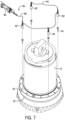
Fig. 1 is an exploded view of the headnut and burn ring of the retainer assembly of the present disclosure in a condition for lifting and installation; -
Fig. 2A is a magnified section view showing the attachment of a headnut to a burn ring; -
Fig. 2B is a section view similar toFig. 2A showing the connection between the headnut and the burn ring; -
Fig. 2C is a section view showing the mechanical connection between the headnut and burn ring prior to installation onto the mainshaft; -
Fig. 2D is a section view showing the position of one of a plurality of jacking bolts received within the headnut; -
Fig. 3 is an exploded view showing the position of the headnut and burn ring above the mainshaft of a gyratory crusher prior to installation; -
Fig. 4 is a section view showing the movement of the combination of the headnut and burn ring along the bearing sleeve; -
Fig. 5 is a perspective view showing the position of the headnut and burn ring to hold the mantle in place on the mainshaft; -
Fig. 6 is a section view similar toFig. 4 showing the final position of the headnut and burn ring; -
Fig. 7 is an exploded view showing the hydraulic kit relative to the installed headnut and burn ring; -
Fig. 8 is a section view showing the removal of the connecting bolts used to secure the headnut to the burn ring; -
Fig. 9 is a partial section view showing the installation of one of the hydraulic cylinders of the hydraulic kit; -
Fig. 10 is a perspective view showing the connection of the hydraulic kit and the position of one or more shims; -
Fig. 11 is a top view of one of the shims shown inFig. 10 ; -
Fig. 12 is a section view illustrating the pressurization of the hydraulic cylinders to create a gap between the headnut and burn ring; -
Fig. 13 is a section view illustrating the movement of the jacking bolts to maintain the created gap and the insertion of a shim; -
Fig. 14 is an exploded perspective view of the installation of the headnut cover; -
Fig. 15 is a magnified, section view showing the installation of the headnut cover onto the headnut; -
Fig. 16 is a perspective view showing the installation of the headnut cover; and -
Fig. 17 is a section view showing the attachment of the headnut cover. -
Figs. 1 and3 generally illustrate several of the components of the retainer assembly constructed in accordance with the present disclosure. As illustrated inFig. 3 , the illustrated components of theretainer assembly 10 are designed to be received along a bearingsleeve 12 that is positioned to surround amain shaft 14 of a gyratory crusher. Themainshaft 14 receives and supports amantle 16 that is fitted around the outside of themainshaft 14. Themantle 16 provides a replaceable wearing surface that needs to be replaced upon wear. Themantle 16 is held in place along themainshaft 14 through use of theretainer assembly 10. - As shown in
Fig. 1 , theretainer assembly 10 includes aheadnut 18 and aburn ring 20. Theheadnut 18 is a generally annular member formed from a durable metal material that includes a series ofinternal threads 22 formed along an annularinner surface 24. Theinternal threads 22 are designed to threadedly engage a series ofexternal threads 26 formed on the lower end of the bearingsleeve 12. As the illustrated portion of theretainer assembly 10 is rotated along theexternal threads 26, theretainer assembly 10 contacts atop edge 28 of themantle 16 to hold themantle 16 in place along the mainshaft. As illustrated inFig. 3 , themainshaft 14 includes a liftinglug 30 along the top end that provides a point of attachment for removing the entire mainshaft. - Referring back to
Fig. 1 , theheadnut 18 includes amain body 31 that extends between a first,top face surface 32 and a second,bottom face surface 34. The annularmain body 31 that extends between thetop face surface 32 and thebottom face surface 34 further defines theinner surface 24 that includes thethreads 22. In accordance with the present disclosure, theheadnut 18 includes a first series ofbores 36 that each extend through the body from thefirst face surface 32 to thesecond face surface 34. In the embodiment illustrated, the first series ofbores 36 includes a total of four bores although other numbers are possible. Theheadnut 18 also includes a second series ofbores 38 that also extend through the body from thefirst face surface 32 to thesecond face surface 34. In the embodiment illustrated, the second series ofbores 38 eight bores although other numbers are possible - In the embodiment shown in
Fig. 1 , each of the second series ofbores 38 are designed to receive one of a plurality of jackingbolts 40. Each of the jackingbolts 40 includes an externally threaded main body that extends between ahead 42 and acontact end 44. Each of the second series ofbores 38 includes a threaded inner surface that is designed to threadedly receive and engage the outer surface of one of the jackingbolts 40. - The first series of
bores 36 are designed to initially receive one of a plurality ofconnectors 46 that include an externally threaded outer shaft that extends between ahead 48 and alower end 50. Awasher 52 is included as part of theconnector 46 to prevent thehead 48 from entering into therespective bore 36. - In the embodiment illustrated in
Fig. 1 , theretainer assembly 10 includes theburn ring 20. However, it is contemplated that theretainer assembly 10 could be constructed in some embodiments in which theburn ring 20 is eliminated. In such an embodiment, the top edge of the mantle would be formed from a stronger material and would replace the function of the burn ring as discussed below. In another contemplated embodiment, the thickness of theburn ring 20 could be greatly reduced and theburn ring 20 could be formed from a stronger material such that a reduced thickness burn ring could carry out the functions set forth below. In the embodiment shown inFig. 1 , theburn ring 20 includes afirst face surface 54 and asecond face surface 56 that define the thickness of the annular body. As illustrated inFig. 1 , theburn ring 20 includes a plurality of dowel pins 58 that are each received within one of a plurality of dowel pin bores 60, which are best shown inFig. 2A . Each of the dowel pin bores 60 is sized to receive afirst end 62 of thedowel pin 58. The upper end of the dowel pin bore 60 defines asupport shoulder 64 that allows thedowel pin 58 to securely seat within the top end of the dowel pin bore 60. Thedowel pin 58 is designed to be pressed into place in theburn ring 20 as shown inFig. 2A . In a contemplated alternate embodiment, the dowel pins 58 could be welded in place from underneath or a combination of welding and friction could be used to hold the dowel pins 58 in place. The outer diameter of thedowel pin 58 is designed to be received within a receivingportion 66 that is formed as part of a cover member bore 68 that also extends between thefirst face 32 and thesecond face surface 34 of theheadnut 18. - As can be understood in
Figs. 2A and 2B , when theheadnut 18 is moved downward toward theburn ring 20, the series of dowel pins 58 are received within the receivingportions 66 of the cover member bores 68 such that the dowel pins 58 create a friction fit to retain theburn ring 20 in contact with thesecond face surface 34 of theheadnut 18, as best shown inFig. 2B . In the configuration shown inFig. 2B , theheadnut 18 and theburn ring 20 are joined to each other in an initial configuration. The dowel pins 58 create a light press fit that holds the two components in this initial configuration. - Referring now to
Fig. 2C , when theheadnut 18 and theburn ring 20 are joined to each other through the use of the dowel pins, theheadnut 18 can be more securely connected to theburn ring 18 by using the series ofconnectors 46. As indicated previously, each of theconnectors 46 includes ahead 48 and an externally threadedshaft 49. The lower end of the externally threadedshaft 49 is threadedly received within one of a plurality of attachment bores 70 that extend through theburn ring 20 from thefirst face surface 54 to thesecond face surface 56. Thewasher 52 is positioned below thehead 48 to hold the head of theconnector 46 above the inner diameter of the first series ofbores 36. The threaded interaction between theshaft 49 and the internal threads formed in the attachment bore 70 securely attaches theheadnut 18 to theburn ring 20. As illustrated inFig. 1 , in the embodiment illustrated, fourseparate connectors 46 are utilized and are spaced around the outer diameter of theheadnut 18. - Referring now to
Fig. 2D , when the series ofconnectors 46 are used to join theheadnut 18 to theburn ring 20, each of the individual jackingbolts 40 can be threadedly inserted into the second series ofbores 38. Each of the jackingbolts 40 includes a recessedengagement portion 72 that extends into the body of the jackingbolt 40 from thetop head portion 42. The main body of the jackingbolt 40 includes a series of external threads that engage a series of internal threads formed within each of the second series ofbores 38. The length of the jackingbolt 40 is selected such that thecontact end 44 is slightly spaced from thecontact pads 74 that are slightly recessed from thefirst face surface 54 of theburn ring 20. In this manner, the jackingbolt 40 is entirely received within one of the second series ofbores 38 during the initial installation process and does not exert any force on theburn ring 20. - As can be seen in
Fig. 3 , a series of liftingbolts 76 can be installed on the first face surface of theheadnut 18. The liftingbolts 76 provide a point of attachment for lifting the combination of theheadnut 18 andburn ring 20. As illustrated inFig. 3 , when theretainer assembly 10 is being lifted, theentire retainer assembly 10 can be lowered until the threaded portion of the headnut 18 contacts theexternal threads 26 formed on the bearingsleeve 12.Fig. 4 illustrates the initial contact between thethreads 26 formed on the bearingsleeve 12 and thethreads 22 formed along theinner surface 24 of theheadnut 18. Upon this initial interaction, the combination of theheadnut 18 and theburn ring 20 can be rotated using hand tools to cause theheadnut 18 andburn ring 20 to move in a downward direction as illustrated byarrow 78. The rotation of theretainer assembly 10 can continue until thesecond face surface 56 of the burn ring comes into contact with thetop edge 28 of themantle 16. This interaction is best shown inFig. 6 . During installation in accordance with the present disclosure, the combination of the headnut and burn ring are threaded into place utilizing only a relatively small amount of force, such as by hand or by using a hand operated tool. The hand-tightening of the headnut and burn ring into contact with thetop edge 28 of themantle 16 is the initial step in the attachment process in accordance with the present disclosure.Fig. 5 shows this initial positioning of the retainer assembly along themainshaft 14. In this position, the retainer assembly lightly holds themantle 16 in place. In this configuration, theconnectors 46 are still used to connect theheadnut 18 to theburn ring 20. - Referring now to
Fig. 7 , once the combination of theheadnut 18 and theburn ring 20 are installed along the bearingsleeve 12, each of theindividual connectors 46 can be removed and ahydraulic kit 80 can be installed to perform the next step in the attachment process for securing themantle 16 to the mainshaft. Thehydraulic kit 80 is part of the entire retainer assembly and is used during the installation process as will be described. Although ahydraulic kit 80 is shown, other pressurized fluids or gases could be used in place of hydraulic fluid. - In the embodiment shown in
Fig. 7 , thehydraulic kit 80 includes a plurality of individualhydraulic cylinders 82 that are each connected to each other through afluid line 84. Thehydraulic fluid line 84 provides a fluid connection for hydraulic fluid to pass between each of theindividual cylinders 82. The endhydraulic cylinder 82 is connected to a supply of pressurized hydraulic fluid 86 through asupply line 88. When thesupply line 88 is connected to the supply ofhydraulic fluid 86, the pressurized hydraulic fluid can flow between each of the individualhydraulic cylinders 82 in a well-known manner. The supply ofhydraulic fluid 86 can be any type of hydraulic fluid supply that provides pressurized fluid at a desired fluid pressure. A hand pump is shown in the embodiment ofFig. 7 , although other sources of pressure are contemplated as being within the scope of the present disclosure. In addition, although pressurized hydraulic fluid is described, other pressurized liquids or gases could be connected to the plurality of cylinders to provide the required driving force to move the cylinder rod and internal piston. As an exemplary alternate embodiment, the supply of pressurized fluid could be pressurized air or other gas and the cylinders could be gas or air actuated cylinders. - Referring now to
Fig. 8 , before the individualhydraulic cylinders 82 can be installed, each of theconnectors 46 are removed from the respective first series ofbores 36. Once each of theconnectors 46 have been removed from the first series ofbores 36, the individual hydraulic cylinders can be installed in the same first series ofbores 36. Thus, the plurality ofconnectors 46 must be removed before the plurality ofhydraulic cylinders 82 can be installed. - Referring now to
Fig. 9 , each of the individualhydraulic cylinders 82 includes amain cylinder body 90. Thecylinder body 90 includes a series ofexternal threads 92. Theexternal threads 92 on thecylinder body 90 are configured to threadedly engage the internal threads formed along the inner surface of each of the first series ofbores 36. In this manner, thehydraulic cylinders 82 can be threadedly received within the plurality of first series ofbores 36. - As illustrated in
Fig. 9 , each of thehydraulic cylinders 82 includes anend effector 94 that is attached to acylinder rod 96. Thecylinder rod 96 is designed to be extended and retracted from within thecylinder body 90 upon application of pressurized hydraulic fluid to thehydraulic cylinder 82. Theend effector 94 is shown inFig. 9 in a retracted position in which theend effector 94 is slightly spaced from thefirst face surface 54 of theburn ring 20. Thus, in the non-pressurized condition, theend effector 94 does not exert any force on theburn ring 20. - During the pressurization process, hydraulic fluid is applied to each of the individual
hydraulic cylinders 82 as best shown inFig. 12 . When hydraulic fluid is applied to thehydraulic cylinder 82, thecylinder rod 96 extends from thecylinder body 90 such that theend effector 94 contacts thefirst face surface 54 of theburn ring 20. Since theend effector 94 is moved under the pressure created by the supply of hydraulic fluid, the downward movement of theend effector 94 creates a corresponding upward movement of theheadnut 18 away from theburn ring 20. The upward movement of theheadnut 18 creates a physical interaction between the threaded portion of theheadnut 18 and the threaded portion of the bearingsleeve 12. The physical interaction between the threaded portions of theheadnut 18 and the bearingsleeve 12 creates a locking force on theburn ring 20 and thus themantle 16. - As illustrated in
Fig. 12 , when the individualhydraulic cylinders 82 are pressurized, the downward movement of theend effector 94 creates agap 98 between thesecond face surface 34 of theheadnut 18 and thefirst face surface 54 of theburn ring 20. Thegap 98 created can have range of sizes. In the embodiment illustrated, thegap 98 has a dimension of approximately 3.2 millimeters, although other sizes for thegap 98 are certainly contemplated as being within the scope of the present disclosure. - Referring now to
Fig. 13 , once thegap 98 has been created through the pressurization of the individualhydraulic cylinders 82, the size of the gap can be maintained by use of the series of jackingbolts 40. Specifically each of the individual jackingbolts 40 is rotated within the respective bore to cause thecontact end 44 of the jackingbolt 40 to contact thefirst surface 54 of theburn ring 20 as illustrated inFig. 13 . Since each of the jackingbolts 40 is threaded into one of the second series ofbores 38, the plurality of jackingbolts 40 can be used to maintain thegap 98 even when the individualhydraulic cylinders 82 are depressurized. - In accordance with the present disclosure, once the jacking
bolts 40 are rotated into contact with theburn ring 20, one or moreindividual shims 100 can be inserted into thegap 98 to maintain the gap during operation of the gyratory crusher. In the embodiment illustrated inFigs. 10 and 11 , theshims 100 are formed as separate segments that can be combined to create either an entire annular ring or portions of an annular ring. It is contemplated that multiple numbers ofshims 100 could be utilized to help maintain the size of the gap between the headnut and the burn ring. In the embodiment shown inFig. 11 , the individual shims include a series ofcutouts 102 that are sized to receive the contact end of each of the jackingbolts 40 and the dowel pins. In this manner, theshims 100 can be inserted as shown inFig. 13 while the jackingbolts 40 maintain the size of thegap 98 and the dowel pins join and align the headnut and the burn ring. Further, thecutouts 102 can also allow theshim 100 to be inserted while the hydraulic cylinders are pressurized and the dowel pins are installed, as shown inFig. 12 . - Once the
individual shims 100 have been securely positioned in place, the hydraulic fluid applied to each of the individual hydraulic cylinders can be removed. The combination of the jackingbolts 40 andshims 100 maintain thegap 98 and also maintain the physical interaction between the threaded portions of theheadnut 18 and the threaded portion of the bearing sleeve. After the hydraulic fluid has been removed from each of thecylinders 82, the threaded bodies of each of thecylinders 82 can be rotated to remove thehydraulic cylinders 82 from theheadnut 18. -
Fig. 14 illustrates the installed headnut and burn ring after the removal of the hydraulic cylinders as compared to the embodiment shown inFig. 10 . Once the hydraulic cylinders of the hydraulic kit are removed, aheadnut cover 104 can be installed over the combination of theheadnut 18 and theburn ring 20. Theheadnut cover 104 is designed to cover theheadnut 18 during operation of the gyratory crusher to reduce the damage to theheadnut 18. Theheadnut cover 104 is an annular member that includes atop face surface 106 that includes a plurality ofbores 108 that are each designed to receive threadedconnector 110. Each threadedconnector 110 includes a threadedshaft 112 and ahead 114, as illustrated inFig. 15 . Referring back toFig. 14 , theheadnut cover 104 includes a plurality of liftinglugs 116 that provide a point of attachment for lifting theheadnut cover 104 and installing it over theheadnut 18. - As illustrated in the section view of
Fig. 15 , theheadnut cover 104 includes atop wall 118 and a dependingside wall 120. The dependingside wall 120 is connected to thetop wall 118 along the radialouter edge 122. Theside wall 120 is designed to have an inner circumference that is designed to fit over theouter surface 124 of theheadnut 18. - The
bores 108 extending into thetop face surface 106 are each designed to include aninternal shoulder 126 that is designed to receive thehead 114 of one of theconnectors 110.Fig. 17 illustrates the mounting of theheadnut cover 104 onto the combination of theheadnut 18 and theburn ring 20. In this configuration, the threaded shaft of theconnector 110 is received within the internal threaded portion of one of the cover member bores 68. In this manner,headnut cover 104 can be securely attached to the headnut as best illustrated inFigs. 16 and 17 . - During replacement of
mantle 16,headnut cover 104 is first removed from theheadnut 18 by removing the series ofconnectors 110. Once theheadnut cover 104 is removed, theburn ring 20 can be cut using a torch, which removes the tension on theheadnut 18. Theheadnut 18 can then be rotated away from themantle 16 and the mantle removed from the mainshaft. - In another embodiment, once the
headnut cover 104 has been removed, the plurality ofhydraulic cylinders 82 could be reinstalled into the first series of bores in the headnut. Once thehydraulic cylinders 82 of the hydraulic kit are reinstalled, the pressurized hydraulic fluid can again be applied to thehydraulic cylinders 82 to help loosen the connection between the headnut and the mainshaft. Once the threaded connection is loosened, the jacking bolts could be retracted combination of the headnut and burn ring could be removed, which would allow for reuse of the burn ring. - This written description uses examples to disclose the invention, including the best mode, and also to enable any person skilled in the art to make and use the invention. The scope of the invention is defined by the claims.
Claims (15)
- A retainer assembly (10) for securing a mantle (16) on a mainshaft (14) of a gyratory crusher, the assembly comprising:a headnut (18) having a body (31) defined by a first face surface (32) and a second face surface (34), the headnut including first series of bores (36) extending through the body and a second series of bores (38) extending through the body;a plurality of jacking bolts (40) each received in one of the second series of bores (38) formed in the headnut (18); anda plurality of cylinders (82) and a supply (86) of pressurized fluid in communication with the plurality of cylinders (82), wherein the plurality of cylinders (82) are each received in one of the first series of bores (36) in the headnut,wherein when the supply (86) of pressurized fluid is supplied to the plurality of cylinders (82), a gap is created between the second face surface (34) of the headnut (18) and the mantle (16).
- The retainer assembly (10) of claim 1 further comprising a burn ring (20) positioned in contact with the second face surface (34) of the headnut (18) and having a body, wherein the burn ring (20) is positioned between the mantle (16) and the headnut (18) when the headnut (18) is installed on the mainshaft (14).
- The retainer assembly (10) of claim 2 further comprising a plurality of connectors (46) each positionable to extend through the first series of bores (36) in the headnut (18) and to be received in one of a plurality of threaded bores (70) formed in the body of the burn ring (20) to join the headnut (18) to the burn ring (20) for installation onto the mainshaft (14).
- The retainer assembly (10) of claim 1 wherein each of the cylinders (82) includes a cylinder body (90) having a threaded outer surface (92) that engages an internally threaded inner surface of the first series of bores (36) formed in the headnut (18).
- The retainer assembly (10) of claim 4 wherein each of the cylinders (82) includes an end effector (94) that extends from the cylinder (82) when the pressurized fluid is supplied to the cylinder (82).
- The retainer assembly (10) of claim 1 further comprising a shim (100) that is positionable within the gap (98).
- The retainer assembly (10) of claim 1 wherein each of the jacking bolts (40) threadedly engages one of the second series of bores (38) formed in the headnut (18).
- The retainer assembly (10) of claim 1 further comprising a headnut cover (104) configured to be received on the headnut (18), the headnut cover (104) including a plurality of alignment bosses sized to be received in one of the first bores (36) formed in the headnut (18).
- A method of securing a mantle (16) to a mainshaft (14) of a gyratory crusher that includes an externally threaded engagement portion (26), comprising:providing a headnut (18) having a first series of bores (36) and a second series of bores (38) each extending through a body of the headnut (18) from a first face surface (32) to a second face surface (34), the headnut (18) further including an internally threaded inner surface (24);positioning a burn ring (20) in contact with the second face surface (34) of the headnut (18);connecting the burn ring (20) to the headnut (18);installing the combination of the headnut (18) and the burn ring (20) along the mainshaft (14) such that the burn ring (20) contacts the mantle (16) and the internally threaded surface (24) of the headnut (18) engages the externally threaded engagement portion (26) of the mainshaft (14);installing a plurality of jacking bolts (40) in the second series of bores (38) formed in the headnut (18);installing a plurality of cylinders (82) in at least some of the first series of bores (36) formed in the headnut (18);supplying pressurized fluid to the plurality of cylinders (82) to create a locking force between the headnut (18) and the mainshaft (14) and to create a gap (98) below the second face surface (34) of the headnut (18);moving the plurality of jacking bolts (40) relative to the headnut (18) to maintain the locking force and the gap (98);removing the supply (86) of pressurized fluid; andremoving the cylinders (82) from the headnut (18).
- The method of claim 9 wherein the burn ring (20) is connected to the headnut (18) by a plurality of connectors (46) that each extend through one of the first series of bores (36) and are each received in the burn ring (20).
- The method of claim 10 further comprising the step of removing the plurality of connectors (46) before supplying the pressurized fluid to the plurality of cylinders (82).
- The method of claim 9 wherein each of the cylinders (82) includes an end effector (94) that extends from the cylinder (82) upon the supply of fluid to the cylinder (82), wherein the end effector (94) contacts the burn ring (20).
- The method of claim 9 wherein each of the cylinders (82) includes a threaded outer surface (92) that is received in one of the first series of bores (36).
- The method of claim 9 further comprising the step of inserting one or more shims (100) into the gap (98) to maintain the locking force and the gap.
- A gyratory crusher comprising:a mainshaft (14);a mantle (16) positioned along the mainshaft (14);a retainer assembly (10) for securing the mantle (16) on the mainshaft (14), the retainer assembly (10) comprising:a headnut (18) having a body (31) defined by a first face surface (32) and a second face surface (34), the headnut (18) including first series of bores (36) extending through the body and a second series of bores (38) extending through the body;a burn ring (20) positioned in contact with the second face surface (34) of the headnut (18) and having a body;a plurality of jacking bolts (40) each received in one of the second series of bores (38) formed in the headnut (18); anda plurality of cylinders (82) in communication with a supply (86) of pressurized fluid, wherein the plurality of cylinders (82) are each received in one of the first series of bores (36) in the headnut (18),wherein when the supply (86) of pressurized fluid is supplied to the plurality of cylinders (82), a gap (98) is created between the second face surface (34) of the headnut (18) and the burn ring (20).
Priority Applications (1)
| Application Number | Priority Date | Filing Date | Title |
|---|---|---|---|
| RS20250578A RS66883B1 (en) | 2021-05-21 | 2022-05-19 | Mantle retaining system and method for a gyratory crusher |
Applications Claiming Priority (2)
| Application Number | Priority Date | Filing Date | Title |
|---|---|---|---|
| US17/326,466 US11679389B2 (en) | 2021-05-21 | 2021-05-21 | Mantle retaining system and method for a gyratory crusher |
| PCT/US2022/029993 WO2022246040A1 (en) | 2021-05-21 | 2022-05-19 | Mantle retaining system and method for a gyratory crusher |
Publications (2)
| Publication Number | Publication Date |
|---|---|
| EP4340998A1 EP4340998A1 (en) | 2024-03-27 |
| EP4340998B1 true EP4340998B1 (en) | 2025-04-16 |
Family
ID=82019333
Family Applications (1)
| Application Number | Title | Priority Date | Filing Date |
|---|---|---|---|
| EP22729957.5A Active EP4340998B1 (en) | 2021-05-21 | 2022-05-19 | Mantle retaining system and method for a gyratory crusher |
Country Status (13)
| Country | Link |
|---|---|
| US (1) | US11679389B2 (en) |
| EP (1) | EP4340998B1 (en) |
| CN (2) | CN217594675U (en) |
| AU (1) | AU2022279220A1 (en) |
| BR (1) | BR112023024338A2 (en) |
| CA (1) | CA3219121A1 (en) |
| CL (1) | CL2023003439A1 (en) |
| FI (1) | FI4340998T3 (en) |
| MX (1) | MX2023013761A (en) |
| PE (1) | PE20240335A1 (en) |
| RS (1) | RS66883B1 (en) |
| WO (1) | WO2022246040A1 (en) |
| ZA (1) | ZA202310562B (en) |
Families Citing this family (3)
| Publication number | Priority date | Publication date | Assignee | Title |
|---|---|---|---|---|
| US11679389B2 (en) * | 2021-05-21 | 2023-06-20 | Metso Outotec USA Inc. | Mantle retaining system and method for a gyratory crusher |
| US11911773B2 (en) * | 2022-07-19 | 2024-02-27 | Kleemann Gmbh | Apparatus and method for attaching a crushing mantle of a cone crusher to a carrier cone of the cone crusher and for detaching the crushing mantle from the carrier cone |
| EP4566717A1 (en) * | 2023-12-05 | 2025-06-11 | FLSmidth A/S | Guiding tool for installing head nut of crusher |
Family Cites Families (13)
| Publication number | Priority date | Publication date | Assignee | Title |
|---|---|---|---|---|
| DE1283654B (en) * | 1966-03-10 | 1968-11-21 | Kloeckner Humboldt Deutz Ag | Rotary crusher with hydraulic clamping device for the installation and removal of the crushing cone |
| US6299083B1 (en) | 1999-06-01 | 2001-10-09 | Svedala Industries, Inc. | Burning ring and head nut connection for gyratory crusher mantle |
| US8944356B2 (en) | 2009-01-29 | 2015-02-03 | Metso Minerals Inc. | Fastening device, a cone crusher and a method for fastening an inner crushing blade to a head of a cone crusher |
| US9157469B2 (en) | 2011-07-08 | 2015-10-13 | Metso Minerals Industries, Inc. | Locking nut assembly for a cone crusher |
| DE102014105029A1 (en) | 2014-04-09 | 2015-10-15 | Thyssenkrupp Ag | Fixing the crushing cone in a cone crusher |
| EP2929940A1 (en) | 2014-04-09 | 2015-10-14 | Sandvik Intellectual Property AB | Inner crushing shell retaining assembly |
| US20160051988A1 (en) * | 2014-08-19 | 2016-02-25 | Metso Minerals Industries, Inc. | Top service clamping cylinders for a gyratory crusher |
| EP3132851B1 (en) | 2015-08-21 | 2019-01-30 | Metso Minerals Industries, Inc. | Anti-spin dust seal for cone and gyratory crushers |
| EP3454990B1 (en) * | 2016-05-10 | 2020-06-24 | FLSmidth A/S | Locking bolt assembly for a crusher device |
| US20190264726A1 (en) | 2018-02-28 | 2019-08-29 | Caleb Hunter | Mantle Clamp Configuration |
| AU2018247208B2 (en) * | 2018-10-09 | 2025-02-27 | Technofast Industries Pty Ltd | Hydraulic Mantle Assembly System for a Gyratory Rock Crusher |
| WO2021013329A1 (en) | 2019-07-22 | 2021-01-28 | Sandvik Srp Ab | Retaining assembly for inner crushing shell of gyratory crusher |
| US11679389B2 (en) * | 2021-05-21 | 2023-06-20 | Metso Outotec USA Inc. | Mantle retaining system and method for a gyratory crusher |
-
2021
- 2021-05-21 US US17/326,466 patent/US11679389B2/en active Active
-
2022
- 2022-05-19 EP EP22729957.5A patent/EP4340998B1/en active Active
- 2022-05-19 PE PE2023003090A patent/PE20240335A1/en unknown
- 2022-05-19 AU AU2022279220A patent/AU2022279220A1/en active Pending
- 2022-05-19 RS RS20250578A patent/RS66883B1/en unknown
- 2022-05-19 MX MX2023013761A patent/MX2023013761A/en unknown
- 2022-05-19 BR BR112023024338A patent/BR112023024338A2/en unknown
- 2022-05-19 CA CA3219121A patent/CA3219121A1/en active Pending
- 2022-05-19 FI FIEP22729957.5T patent/FI4340998T3/en active
- 2022-05-19 WO PCT/US2022/029993 patent/WO2022246040A1/en not_active Ceased
- 2022-05-23 CN CN202221259987.5U patent/CN217594675U/en active Active
- 2022-05-23 CN CN202210562884.4A patent/CN115364930A/en active Pending
-
2023
- 2023-11-14 ZA ZA2023/10562A patent/ZA202310562B/en unknown
- 2023-11-20 CL CL2023003439A patent/CL2023003439A1/en unknown
Also Published As
| Publication number | Publication date |
|---|---|
| AU2022279220A1 (en) | 2023-11-30 |
| CL2023003439A1 (en) | 2024-07-05 |
| ZA202310562B (en) | 2025-04-30 |
| EP4340998A1 (en) | 2024-03-27 |
| CA3219121A1 (en) | 2022-11-24 |
| MX2023013761A (en) | 2024-02-13 |
| BR112023024338A2 (en) | 2024-02-06 |
| CN115364930A (en) | 2022-11-22 |
| RS66883B1 (en) | 2025-07-31 |
| US20220371021A1 (en) | 2022-11-24 |
| PE20240335A1 (en) | 2024-02-27 |
| WO2022246040A1 (en) | 2022-11-24 |
| US11679389B2 (en) | 2023-06-20 |
| FI4340998T3 (en) | 2025-07-08 |
| CN217594675U (en) | 2022-10-18 |
Similar Documents
| Publication | Publication Date | Title |
|---|---|---|
| US11679389B2 (en) | Mantle retaining system and method for a gyratory crusher | |
| US8832921B2 (en) | Locking nut assembly for a cone crusher | |
| EP2382047B1 (en) | A fastening device, a cone crusher and a method for fastening a mantel to a head of a cone crusher | |
| KR102637500B1 (en) | Hydraulic mantle assembly system for rotary rock crushers | |
| CN107405624A (en) | Wear-resisting body and its manufacture method | |
| US6604699B1 (en) | Method for securing a gyratory crusher mantle | |
| CN101487489B (en) | Pre-stressing apparatus using a split threaded fastener | |
| EP3454990B1 (en) | Locking bolt assembly for a crusher device | |
| US7017683B2 (en) | Cutter for tunnel boring machine | |
| EA046981B1 (en) | ARMOR FIXATION SYSTEM AND METHOD FOR GYRATION CRUSHER | |
| AU2019228596A1 (en) | Mantle clamp configuration | |
| JP3023693U (en) | Hydraulic breaker | |
| CN214159734U (en) | Rolling mortar wall for cone crusher | |
| EP4309791B1 (en) | Apparatus and method for attaching a crushing mantle of a cone crusher to a carrier cone of the cone crusher and for detaching the crushing mantle from the carrier cone | |
| AU2004240243B2 (en) | Sleeve extraction |
Legal Events
| Date | Code | Title | Description |
|---|---|---|---|
| STAA | Information on the status of an ep patent application or granted ep patent |
Free format text: STATUS: UNKNOWN |
|
| STAA | Information on the status of an ep patent application or granted ep patent |
Free format text: STATUS: THE INTERNATIONAL PUBLICATION HAS BEEN MADE |
|
| PUAI | Public reference made under article 153(3) epc to a published international application that has entered the european phase |
Free format text: ORIGINAL CODE: 0009012 |
|
| STAA | Information on the status of an ep patent application or granted ep patent |
Free format text: STATUS: REQUEST FOR EXAMINATION WAS MADE |
|
| 17P | Request for examination filed |
Effective date: 20231115 |
|
| AK | Designated contracting states |
Kind code of ref document: A1 Designated state(s): AL AT BE BG CH CY CZ DE DK EE ES FI FR GB GR HR HU IE IS IT LI LT LU LV MC MK MT NL NO PL PT RO RS SE SI SK SM TR |
|
| DAV | Request for validation of the european patent (deleted) | ||
| DAX | Request for extension of the european patent (deleted) | ||
| GRAP | Despatch of communication of intention to grant a patent |
Free format text: ORIGINAL CODE: EPIDOSNIGR1 |
|
| STAA | Information on the status of an ep patent application or granted ep patent |
Free format text: STATUS: GRANT OF PATENT IS INTENDED |
|
| INTG | Intention to grant announced |
Effective date: 20241111 |
|
| GRAS | Grant fee paid |
Free format text: ORIGINAL CODE: EPIDOSNIGR3 |
|
| GRAA | (expected) grant |
Free format text: ORIGINAL CODE: 0009210 |
|
| STAA | Information on the status of an ep patent application or granted ep patent |
Free format text: STATUS: THE PATENT HAS BEEN GRANTED |
|
| AK | Designated contracting states |
Kind code of ref document: B1 Designated state(s): AL AT BE BG CH CY CZ DE DK EE ES FI FR GB GR HR HU IE IS IT LI LT LU LV MC MK MT NL NO PL PT RO RS SE SI SK SM TR |
|
| REG | Reference to a national code |
Ref country code: GB Ref legal event code: FG4D |
|
| REG | Reference to a national code |
Ref country code: CH Ref legal event code: EP Ref country code: DE Ref legal event code: R096 Ref document number: 602022013276 Country of ref document: DE |
|
| REG | Reference to a national code |
Ref country code: IE Ref legal event code: FG4D |
|
| P01 | Opt-out of the competence of the unified patent court (upc) registered |
Free format text: CASE NUMBER: APP_20554/2025 Effective date: 20250430 |
|
| PGFP | Annual fee paid to national office [announced via postgrant information from national office to epo] |
Ref country code: FI Payment date: 20250530 Year of fee payment: 4 |
|
| REG | Reference to a national code |
Ref country code: FI Ref legal event code: FGE |
|
| PGFP | Annual fee paid to national office [announced via postgrant information from national office to epo] |
Ref country code: RS Payment date: 20250527 Year of fee payment: 4 |
|
| REG | Reference to a national code |
Ref country code: SE Ref legal event code: TRGR |
|
| PGFP | Annual fee paid to national office [announced via postgrant information from national office to epo] |
Ref country code: AT Payment date: 20250721 Year of fee payment: 4 |
|
| PGFP | Annual fee paid to national office [announced via postgrant information from national office to epo] |
Ref country code: SE Payment date: 20250528 Year of fee payment: 4 |
|
| REG | Reference to a national code |
Ref country code: NL Ref legal event code: MP Effective date: 20250416 |
|
| PG25 | Lapsed in a contracting state [announced via postgrant information from national office to epo] |
Ref country code: NL Free format text: LAPSE BECAUSE OF FAILURE TO SUBMIT A TRANSLATION OF THE DESCRIPTION OR TO PAY THE FEE WITHIN THE PRESCRIBED TIME-LIMIT Effective date: 20250416 |
|
| REG | Reference to a national code |
Ref country code: AT Ref legal event code: MK05 Ref document number: 1785230 Country of ref document: AT Kind code of ref document: T Effective date: 20250416 |
|
| PG25 | Lapsed in a contracting state [announced via postgrant information from national office to epo] |
Ref country code: PT Free format text: LAPSE BECAUSE OF FAILURE TO SUBMIT A TRANSLATION OF THE DESCRIPTION OR TO PAY THE FEE WITHIN THE PRESCRIBED TIME-LIMIT Effective date: 20250818 Ref country code: ES Free format text: LAPSE BECAUSE OF FAILURE TO SUBMIT A TRANSLATION OF THE DESCRIPTION OR TO PAY THE FEE WITHIN THE PRESCRIBED TIME-LIMIT Effective date: 20250416 |
|
| REG | Reference to a national code |
Ref country code: LT Ref legal event code: MG9D |
|
| PG25 | Lapsed in a contracting state [announced via postgrant information from national office to epo] |
Ref country code: GR Free format text: LAPSE BECAUSE OF FAILURE TO SUBMIT A TRANSLATION OF THE DESCRIPTION OR TO PAY THE FEE WITHIN THE PRESCRIBED TIME-LIMIT Effective date: 20250717 Ref country code: NO Free format text: LAPSE BECAUSE OF FAILURE TO SUBMIT A TRANSLATION OF THE DESCRIPTION OR TO PAY THE FEE WITHIN THE PRESCRIBED TIME-LIMIT Effective date: 20250716 |
|
| PG25 | Lapsed in a contracting state [announced via postgrant information from national office to epo] |
Ref country code: PL Free format text: LAPSE BECAUSE OF FAILURE TO SUBMIT A TRANSLATION OF THE DESCRIPTION OR TO PAY THE FEE WITHIN THE PRESCRIBED TIME-LIMIT Effective date: 20250416 |
|
| PGFP | Annual fee paid to national office [announced via postgrant information from national office to epo] |
Ref country code: TR Payment date: 20250707 Year of fee payment: 4 |
|
| PG25 | Lapsed in a contracting state [announced via postgrant information from national office to epo] |
Ref country code: BG Free format text: LAPSE BECAUSE OF FAILURE TO SUBMIT A TRANSLATION OF THE DESCRIPTION OR TO PAY THE FEE WITHIN THE PRESCRIBED TIME-LIMIT Effective date: 20250416 |
|
| PG25 | Lapsed in a contracting state [announced via postgrant information from national office to epo] |
Ref country code: HR Free format text: LAPSE BECAUSE OF FAILURE TO SUBMIT A TRANSLATION OF THE DESCRIPTION OR TO PAY THE FEE WITHIN THE PRESCRIBED TIME-LIMIT Effective date: 20250416 Ref country code: AT Free format text: LAPSE BECAUSE OF FAILURE TO SUBMIT A TRANSLATION OF THE DESCRIPTION OR TO PAY THE FEE WITHIN THE PRESCRIBED TIME-LIMIT Effective date: 20250416 |
|
| PG25 | Lapsed in a contracting state [announced via postgrant information from national office to epo] |
Ref country code: IS Free format text: LAPSE BECAUSE OF FAILURE TO SUBMIT A TRANSLATION OF THE DESCRIPTION OR TO PAY THE FEE WITHIN THE PRESCRIBED TIME-LIMIT Effective date: 20250816 |
|
| PG25 | Lapsed in a contracting state [announced via postgrant information from national office to epo] |
Ref country code: LV Free format text: LAPSE BECAUSE OF FAILURE TO SUBMIT A TRANSLATION OF THE DESCRIPTION OR TO PAY THE FEE WITHIN THE PRESCRIBED TIME-LIMIT Effective date: 20250416 |
|
| REG | Reference to a national code |
Ref country code: DE Ref legal event code: R119 Ref document number: 602022013276 Country of ref document: DE |
|
| REG | Reference to a national code |
Ref country code: CH Ref legal event code: H13 Free format text: ST27 STATUS EVENT CODE: U-0-0-H10-H13 (AS PROVIDED BY THE NATIONAL OFFICE) Effective date: 20251223 |
|
| PG25 | Lapsed in a contracting state [announced via postgrant information from national office to epo] |
Ref country code: SM Free format text: LAPSE BECAUSE OF FAILURE TO SUBMIT A TRANSLATION OF THE DESCRIPTION OR TO PAY THE FEE WITHIN THE PRESCRIBED TIME-LIMIT Effective date: 20250416 Ref country code: DK Free format text: LAPSE BECAUSE OF FAILURE TO SUBMIT A TRANSLATION OF THE DESCRIPTION OR TO PAY THE FEE WITHIN THE PRESCRIBED TIME-LIMIT Effective date: 20250416 |
|
| PG25 | Lapsed in a contracting state [announced via postgrant information from national office to epo] |
Ref country code: LU Free format text: LAPSE BECAUSE OF NON-PAYMENT OF DUE FEES Effective date: 20250519 |
|
| PG25 | Lapsed in a contracting state [announced via postgrant information from national office to epo] |
Ref country code: CH Free format text: LAPSE BECAUSE OF NON-PAYMENT OF DUE FEES Effective date: 20250531 |
|
| PG25 | Lapsed in a contracting state [announced via postgrant information from national office to epo] |
Ref country code: CZ Free format text: LAPSE BECAUSE OF FAILURE TO SUBMIT A TRANSLATION OF THE DESCRIPTION OR TO PAY THE FEE WITHIN THE PRESCRIBED TIME-LIMIT Effective date: 20250416 |
|
| PG25 | Lapsed in a contracting state [announced via postgrant information from national office to epo] |
Ref country code: EE Free format text: LAPSE BECAUSE OF FAILURE TO SUBMIT A TRANSLATION OF THE DESCRIPTION OR TO PAY THE FEE WITHIN THE PRESCRIBED TIME-LIMIT Effective date: 20250416 |
|
| PG25 | Lapsed in a contracting state [announced via postgrant information from national office to epo] |
Ref country code: SK Free format text: LAPSE BECAUSE OF FAILURE TO SUBMIT A TRANSLATION OF THE DESCRIPTION OR TO PAY THE FEE WITHIN THE PRESCRIBED TIME-LIMIT Effective date: 20250416 |
|
| PG25 | Lapsed in a contracting state [announced via postgrant information from national office to epo] |
Ref country code: IT Free format text: LAPSE BECAUSE OF FAILURE TO SUBMIT A TRANSLATION OF THE DESCRIPTION OR TO PAY THE FEE WITHIN THE PRESCRIBED TIME-LIMIT Effective date: 20250416 |
|
| REG | Reference to a national code |
Ref country code: BE Ref legal event code: MM Effective date: 20250531 |
|
| PG25 | Lapsed in a contracting state [announced via postgrant information from national office to epo] |
Ref country code: MC Free format text: LAPSE BECAUSE OF FAILURE TO SUBMIT A TRANSLATION OF THE DESCRIPTION OR TO PAY THE FEE WITHIN THE PRESCRIBED TIME-LIMIT Effective date: 20250416 |
|
| PLBE | No opposition filed within time limit |
Free format text: ORIGINAL CODE: 0009261 |
|
| STAA | Information on the status of an ep patent application or granted ep patent |
Free format text: STATUS: NO OPPOSITION FILED WITHIN TIME LIMIT |
|
| REG | Reference to a national code |
Ref country code: CH Ref legal event code: L10 Free format text: ST27 STATUS EVENT CODE: U-0-0-L10-L00 (AS PROVIDED BY THE NATIONAL OFFICE) Effective date: 20260225 |
|
| PG25 | Lapsed in a contracting state [announced via postgrant information from national office to epo] |
Ref country code: RO Free format text: LAPSE BECAUSE OF FAILURE TO SUBMIT A TRANSLATION OF THE DESCRIPTION OR TO PAY THE FEE WITHIN THE PRESCRIBED TIME-LIMIT Effective date: 20250416 |
|
| 26N | No opposition filed |
Effective date: 20260119 |
|
| PG25 | Lapsed in a contracting state [announced via postgrant information from national office to epo] |
Ref country code: DE Free format text: LAPSE BECAUSE OF NON-PAYMENT OF DUE FEES Effective date: 20251202 Ref country code: IE Free format text: LAPSE BECAUSE OF NON-PAYMENT OF DUE FEES Effective date: 20250519 |
|
| PG25 | Lapsed in a contracting state [announced via postgrant information from national office to epo] |
Ref country code: BE Free format text: LAPSE BECAUSE OF NON-PAYMENT OF DUE FEES Effective date: 20250531 |
|
| PG25 | Lapsed in a contracting state [announced via postgrant information from national office to epo] |
Ref country code: FR Free format text: LAPSE BECAUSE OF NON-PAYMENT OF DUE FEES Effective date: 20250616 |