EP4340729B1 - Medical device undercarriage and medical device system - Google Patents
Medical device undercarriage and medical device system Download PDFInfo
- Publication number
- EP4340729B1 EP4340729B1 EP21778344.8A EP21778344A EP4340729B1 EP 4340729 B1 EP4340729 B1 EP 4340729B1 EP 21778344 A EP21778344 A EP 21778344A EP 4340729 B1 EP4340729 B1 EP 4340729B1
- Authority
- EP
- European Patent Office
- Prior art keywords
- medical device
- sensitive detector
- undercarriage
- position sensitive
- controller
- Prior art date
- Legal status (The legal status is an assumption and is not a legal conclusion. Google has not performed a legal analysis and makes no representation as to the accuracy of the status listed.)
- Active
Links
Images

Classifications
-
- A—HUMAN NECESSITIES
- A61—MEDICAL OR VETERINARY SCIENCE; HYGIENE
- A61B—DIAGNOSIS; SURGERY; IDENTIFICATION
- A61B6/00—Apparatus or devices for radiation diagnosis; Apparatus or devices for radiation diagnosis combined with radiation therapy equipment
- A61B6/04—Positioning of patients; Tiltable beds or the like
- A61B6/0487—Motor-assisted positioning
-
- A—HUMAN NECESSITIES
- A61—MEDICAL OR VETERINARY SCIENCE; HYGIENE
- A61B—DIAGNOSIS; SURGERY; IDENTIFICATION
- A61B6/00—Apparatus or devices for radiation diagnosis; Apparatus or devices for radiation diagnosis combined with radiation therapy equipment
- A61B6/02—Arrangements for diagnosis sequentially in different planes; Stereoscopic radiation diagnosis
- A61B6/03—Computed tomography [CT]
- A61B6/032—Transmission computed tomography [CT]
-
- G—PHYSICS
- G16—INFORMATION AND COMMUNICATION TECHNOLOGY [ICT] SPECIALLY ADAPTED FOR SPECIFIC APPLICATION FIELDS
- G16H—HEALTHCARE INFORMATICS, i.e. INFORMATION AND COMMUNICATION TECHNOLOGY [ICT] SPECIALLY ADAPTED FOR THE HANDLING OR PROCESSING OF MEDICAL OR HEALTHCARE DATA
- G16H40/00—ICT specially adapted for the management or administration of healthcare resources or facilities; ICT specially adapted for the management or operation of medical equipment or devices
- G16H40/60—ICT specially adapted for the management or administration of healthcare resources or facilities; ICT specially adapted for the management or operation of medical equipment or devices for the operation of medical equipment or devices
- G16H40/63—ICT specially adapted for the management or administration of healthcare resources or facilities; ICT specially adapted for the management or operation of medical equipment or devices for the operation of medical equipment or devices for local operation
-
- A—HUMAN NECESSITIES
- A61—MEDICAL OR VETERINARY SCIENCE; HYGIENE
- A61B—DIAGNOSIS; SURGERY; IDENTIFICATION
- A61B6/00—Apparatus or devices for radiation diagnosis; Apparatus or devices for radiation diagnosis combined with radiation therapy equipment
- A61B6/44—Constructional features of apparatus for radiation diagnosis
- A61B6/4405—Constructional features of apparatus for radiation diagnosis the apparatus being movable or portable, e.g. handheld or mounted on a trolley
-
- A—HUMAN NECESSITIES
- A61—MEDICAL OR VETERINARY SCIENCE; HYGIENE
- A61B—DIAGNOSIS; SURGERY; IDENTIFICATION
- A61B6/00—Apparatus or devices for radiation diagnosis; Apparatus or devices for radiation diagnosis combined with radiation therapy equipment
- A61B6/54—Control of apparatus or devices for radiation diagnosis
-
- A—HUMAN NECESSITIES
- A61—MEDICAL OR VETERINARY SCIENCE; HYGIENE
- A61B—DIAGNOSIS; SURGERY; IDENTIFICATION
- A61B6/00—Apparatus or devices for radiation diagnosis; Apparatus or devices for radiation diagnosis combined with radiation therapy equipment
- A61B6/54—Control of apparatus or devices for radiation diagnosis
- A61B6/547—Control of apparatus or devices for radiation diagnosis involving tracking of position of the device or parts of the device
Definitions
- the present invention relates to a medical device system, and in particular, to a medical device undercarriage.
- a patient is usually moved by a patient support system (examination table).
- a patient support system (examination table).
- the patient is under surgery or has an open wound, the patient cannot be moved and CT scanning is performed by moving a gantry.
- Motion precision is very important for mobile CT and is directly related to image quality of scanning.
- the motion precision of the mobile CT is affected by a variety of factors, including ground flatness and installation precision of a mechanical structure.
- US 2020/245966 A1 discloses a medical imaging apparatus and a control method of the same.
- the medical imaging apparatus including a rotatable gantry in which an X-ray generator configured to generate X-rays and emit the X-rays to an object and an X-ray detector configured to detect the X-rays emitted from the X-ray generator are arranged to face each other, the medical imaging apparatus includes a mover configured to move the medical imaging apparatus, a sensor configured to measure position data according to the movement of the gantry; generate image data based on the detected X-rays, correct the image data based on the measured position data, and generate an X-ray computed tomography (CT) image based on the corrected image data.
- CT computed tomography
- the medical imaging system may include a movable station and a gantry.
- the movable station includes a gantry mount rotatably attached to the gantry.
- the gantry includes an outer C-arm slidably mounted to and operable to slide relative to the gantry mount, an inner C-arm slidably coupled to the outer C-arm and, an imaging signal transmitter and sensor attached to the C-arms.
- the two C-arms work together to provide a full 360 degree rotation of the imaging signal transmitter.
- the movable station may include a motion control system and an imaging control system.
- the motion control system includes omnidirectional wheels for precision controlled-movement of the movable station.
- US 2019/099140 A1 discloses an imaging system.
- the imaging system is operable to acquire and/or generate image data at positions relative to a subject.
- the imaging system includes a drive system configured to move the imaging system.
- US 2020/121267 A1 discloses a mobile imaging system for imaging of patients in medical interventions comprising a ring gantry with a plurality of independently rotating rings whereas a first rotating ring positions an X-ray source with collimator and a second rotating ring positions an image detector such that the region of interest (patient) can be positioned off-centered with respect to the ring center.
- the present invention provides a medical device undercarriage and a medical device system.
- a medical device undercarriage including a pair of front wheels, a pair of rear wheels, a first position sensitive detector located between the pair of front wheels, a second position sensitive detector located between the pair of rear wheels, and a controller; and the controller calculates a gear ratio of the rear wheels according to a position of the first position sensitive detector and a position of the second position sensitive detector.
- E a ( n ) d P 2 ⁇ P 1 1000 + E p n
- d ( P 2 - P 1 ) is a position difference between the first position sensitive detector and the second position sensitive detector.
- K ap , K ai , and K ad are respectively proportional integral differential coefficients of related angles.
- N [25, 1000].
- the front wheel includes a mobile encoder, a mobile motor, and a mobile drive
- the rear wheel includes a steering encoder, a steering motor, and a steering drive.
- a medical device system including a medical device and the medical device undercarriage described above, where the medical device is disposed on the medical device undercarriage, and the controller sends the gear ratio of the rear wheels to the medical device.
- the medical device undercarriage and system of the present invention no track is required to control motion, and no absolutely flat ground is required.
- the medical device undercarriage and system can be used on a relatively flat ground, have low costs, and are slightly environment-dependent.
- FIG. 1 is a schematic structural diagram of a medical device undercarriage 100 according to an embodiment of the present invention.
- FIG. 2 is a functional block diagram of the medical device undercarriage 100 according to an embodiment of the present invention.
- the medical device undercarriage 100 will travel in a Y direction, but in fact it will be offset in an X direction.
- Motion inertia of a gantry is very large, and a back gap exists in a mobile mechanism, so it is difficult to measure a static error.
- a deviation in the X direction should be within 2 mm.
- the medical device undercarriage 100 includes a undercarriage plate 102, a pair of front wheels 106, a pair of rear wheels 104, a first position sensitive detector 120 located between the pair of front wheels 106, a second position sensitive detector 108 located between the pair of rear wheels 104, and a controller 113.
- the first position sensitive detector 120 and the second position sensitive detector 108 emit a laser beam 110.
- the front wheel 106 includes a mobile encoder 109, a mobile motor 107, and a mobile drive 111
- the rear wheel 104 includes a steering encoder 103, a steering motor 101, and a steering drive 105.
- the first position sensitive detector 120 and the second position sensitive detector 108 send their position information to the controller 113.
- the controller 113 calculates a gear ratio of the rear wheels 104 according to a position of the first position sensitive detector 120 and a position of the second position sensitive detector 108.
- a medical device 117 may be disposed on the medical device undercarriage 100, and the controller 113 may send the gear ratio to the medical device 117.
- Offsets of the two positions on the undercarriage 100 relative to the traveling direction may be obtained from the first position sensitive detector 120 and the second position sensitive detector 108.
- the position of the first position sensitive detector 120 is P 1
- the position of the second position sensitive detector 108 is P 2
- the position P 1 of the first position sensitive detector 120 is a position error
- P 2 - P 1 is an angle error.
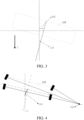
- FIG. 3 is a schematic diagram of a position deviation 112 and an angle deviation 114 of a medical device undercarriage 100 according to an embodiment of the present invention.
- the position deviation is used as an input to the first proportional integral differential (PID) loop, and a half-position PID algorithm is used herein.
- PID proportional integral differential
- a half-position PID algorithm is used herein.
- Deviation values of a position sensitive detector at N sampling points are recorded as input deviation values, and N may be a value between 25 and 1000, which can not only increase reliability of deviation correction, but also reduce processor burden.
- E p ( n ) a position deviation of the first position sensitive detector 120 is E p ( n )
- Nis a positive integer, and dt is a sampling interval
- K pp , K pi , and K pd are respectively proportional integral differential coefficients of related positions, and may be obtained through test.
- the obtained correction deviation is added to adjustment of the angle deviation, so that adjustment of the angle deviation approaches 0 and reduces the position deviation.
- d ( P 2 - P 1 ) is in a unit of micron. Therefore, it needs to be divided by 1000 for unit conversion.
- a correction amount obtained after the PID loop is compared with an existing speed difference, and further correction is performed.
- a rear wheel swivel angle is added, and a deviation angle of the rear wheel is obtained in real time by using a motion center as an origin according to a differential deviation that needs to be corrected.
- K ap , K ai , and K ad are respectively proportional integral differential coefficients of related angles, and may be obtained through test.
- FIG. 4 is a schematic diagram of motion of a medical device undercarriage 100 according to an embodiment of the present invention.
- the rear wheel 104 is deflected around an origin 118, so that a undercarriage plate 102 has path planning 116, thereby returning to the ideal traveling route Y.
- a measurement range of a high-precision position sensitive detector is +/-17 mm, and resolution is 0.01 mm.
- a distance between steering wheels (rear wheels) is 2605 mm, and a diameter of the steering wheel is 198 mm. If only traveling wheels (front wheels) are controlled synchronously in real time, a deviation of 5-7 mm will occur when moving by 1000 mm at 100 mm/s. With the controller of this embodiment, the deviation is reduced to 2 mm.
- the present invention further provides a medical device system, including a medical device 117 and the medical device undercarriage 100.
- the medical device 117 is disposed on the medical device undercarriage 100.
- the controller 113 sends the gear ratio of the rear wheels 104 to the medical device 117.
- the medical device undercarriage and system of the present invention no track is required to control motion, and no absolutely flat ground is required.
- the medical device undercarriage and system can be used on a relatively flat ground, have low costs, and are slightly environment-dependent.
Landscapes
- Health & Medical Sciences (AREA)
- Life Sciences & Earth Sciences (AREA)
- Engineering & Computer Science (AREA)
- Medical Informatics (AREA)
- Biomedical Technology (AREA)
- Public Health (AREA)
- General Health & Medical Sciences (AREA)
- Heart & Thoracic Surgery (AREA)
- High Energy & Nuclear Physics (AREA)
- Pathology (AREA)
- Radiology & Medical Imaging (AREA)
- Nuclear Medicine, Radiotherapy & Molecular Imaging (AREA)
- Physics & Mathematics (AREA)
- Molecular Biology (AREA)
- Surgery (AREA)
- Animal Behavior & Ethology (AREA)
- Optics & Photonics (AREA)
- Biophysics (AREA)
- Veterinary Medicine (AREA)
- Business, Economics & Management (AREA)
- General Business, Economics & Management (AREA)
- Epidemiology (AREA)
- Primary Health Care (AREA)
- Pulmonology (AREA)
- Theoretical Computer Science (AREA)
- Control Of Position, Course, Altitude, Or Attitude Of Moving Bodies (AREA)
- Apparatus For Radiation Diagnosis (AREA)
Description
- The present invention relates to a medical device system, and in particular, to a medical device undercarriage.
- During CT scanning, a patient is usually moved by a patient support system (examination table). However, in some special cases, for example, the patient is under surgery or has an open wound, the patient cannot be moved and CT scanning is performed by moving a gantry. This requires a movable gantry undercarriage that can carry and transport the gantry. With this undercarriage, the gantry can be transported outside the scanning room and used in several rooms.
- Motion precision is very important for mobile CT and is directly related to image quality of scanning. However, the motion precision of the mobile CT is affected by a variety of factors, including ground flatness and installation precision of a mechanical structure.
-
US 2020/245966 A1 discloses a medical imaging apparatus and a control method of the same. The medical imaging apparatus including a rotatable gantry in which an X-ray generator configured to generate X-rays and emit the X-rays to an object and an X-ray detector configured to detect the X-rays emitted from the X-ray generator are arranged to face each other, the medical imaging apparatus includes a mover configured to move the medical imaging apparatus, a sensor configured to measure position data according to the movement of the gantry; generate image data based on the detected X-rays, correct the image data based on the measured position data, and generate an X-ray computed tomography (CT) image based on the corrected image data. -
US 2017/215826 A1 discloses medical imaging devices, systems, and methods. The medical imaging system may include a movable station and a gantry. The movable station includes a gantry mount rotatably attached to the gantry. The gantry includes an outer C-arm slidably mounted to and operable to slide relative to the gantry mount, an inner C-arm slidably coupled to the outer C-arm and, an imaging signal transmitter and sensor attached to the C-arms. The two C-arms work together to provide a full 360 degree rotation of the imaging signal transmitter. The movable station may include a motion control system and an imaging control system. In embodiments, the motion control system includes omnidirectional wheels for precision controlled-movement of the movable station. -
US 2019/099140 A1 discloses an imaging system. The imaging system is operable to acquire and/or generate image data at positions relative to a subject. The imaging system includes a drive system configured to move the imaging system. -
US 2020/121267 A1 discloses a mobile imaging system for imaging of patients in medical interventions comprising a ring gantry with a plurality of independently rotating rings whereas a first rotating ring positions an X-ray source with collimator and a second rotating ring positions an image detector such that the region of interest (patient) can be positioned off-centered with respect to the ring center. - In view of this, the present invention provides a medical device undercarriage and a medical device system.
- According to a first aspect of the present invention, a medical device undercarriage is provided, including a pair of front wheels, a pair of rear wheels, a first position sensitive detector located between the pair of front wheels, a second position sensitive detector located between the pair of rear wheels, and a controller; and the controller calculates a gear ratio of the rear wheels according to a position of the first position sensitive detector and a position of the second position sensitive detector.
- In an embodiment, if a position deviation of the first position sensitive detector is Ep(n), the controller calculates Ep(n) according to the following formula:

- In an embodiment, if the position of the first position sensitive detector is P 1, the position of the second position sensitive detector is P 2, and an angle deviation of the second position sensitive detector is Ea (n), the controller calculates Ea (n) according to the following formula:

- In an embodiment, if the gear ratio of the rear wheels is GR, the controller calculates GR according to the following formula:

- In an embodiment, N ∈ [25, 1000].
- In an embodiment, the front wheel includes a mobile encoder, a mobile motor, and a mobile drive, and the rear wheel includes a steering encoder, a steering motor, and a steering drive.
- According to a second aspect of the present invention, a medical device system is provided, including a medical device and the medical device undercarriage described above, where the medical device is disposed on the medical device undercarriage, and the controller sends the gear ratio of the rear wheels to the medical device.
- For the medical device undercarriage and system of the present invention, no track is required to control motion, and no absolutely flat ground is required. The medical device undercarriage and system can be used on a relatively flat ground, have low costs, and are slightly environment-dependent.
- To enable a person of ordinary skill in the art to understand the foregoing and other features and advantages of the present invention more clearly, exemplary embodiments according to the present invention are described in detail below with reference to the accompany drawings. In the accompany drawings:
-
FIG. 1 is a schematic structural diagram of a medical device undercarriage according to an embodiment of the present invention. -
FIG. 2 is a functional block diagram of a medical device undercarriage according to an embodiment of the present invention. -
FIG. 3 is a schematic diagram of position and angle deviations of a medical device undercarriage according to an embodiment of the present invention. -
FIG. 4 is a schematic diagram of motion of a medical device undercarriage according to an embodiment of the present invention. - In the accompany drawings, reference numerals used are as follows:
100 Medical device undercarriage 110 Laser beam 101 Steering motor 111 Mobile drive 102 Undercarriage plate 112 Position deviation 103 Steering encoder 113 Controller 104 Rear wheel 114 Angle deviation 105 Steering drive 116 Path planning 106 Front wheel 117 Medical device 107 Mobile motor 118 Origin 108 Second position sensitive detector 120 First position sensitive detector 109 Mobile encoder - To make the objective, technical solutions, and advantages of the present invention clearer, the present invention is further described in detail below by using embodiments.
-
FIG. 1 is a schematic structural diagram of amedical device undercarriage 100 according to an embodiment of the present invention.FIG. 2 is a functional block diagram of themedical device undercarriage 100 according to an embodiment of the present invention. Ideally, themedical device undercarriage 100 will travel in a Y direction, but in fact it will be offset in an X direction. Motion inertia of a gantry is very large, and a back gap exists in a mobile mechanism, so it is difficult to measure a static error. To reduce impact on scanning and reconstruction, a deviation in the X direction should be within 2 mm. - As shown in
FIG. 1 and FIG. 2 , themedical device undercarriage 100 includes aundercarriage plate 102, a pair offront wheels 106, a pair ofrear wheels 104, a first positionsensitive detector 120 located between the pair offront wheels 106, a second positionsensitive detector 108 located between the pair ofrear wheels 104, and acontroller 113. The first positionsensitive detector 120 and the second positionsensitive detector 108 emit alaser beam 110. - As shown in
FIG. 2 , thefront wheel 106 includes amobile encoder 109, amobile motor 107, and amobile drive 111, and therear wheel 104 includes asteering encoder 103, asteering motor 101, and asteering drive 105. The first positionsensitive detector 120 and the second positionsensitive detector 108 send their position information to thecontroller 113. Thecontroller 113 calculates a gear ratio of therear wheels 104 according to a position of the first positionsensitive detector 120 and a position of the second positionsensitive detector 108. Amedical device 117 may be disposed on themedical device undercarriage 100, and thecontroller 113 may send the gear ratio to themedical device 117. - Offsets of the two positions on the
undercarriage 100 relative to the traveling direction may be obtained from the first positionsensitive detector 120 and the second positionsensitive detector 108. The position of the first positionsensitive detector 120 is P 1, the position of the second positionsensitive detector 108 is P 2, the position P1 of the first positionsensitive detector 120 is a position error, and P2 - P 1 is an angle error. -
FIG. 3 is a schematic diagram of aposition deviation 112 and anangle deviation 114 of amedical device undercarriage 100 according to an embodiment of the present invention. - First, to reduce the position error of P 1, the position deviation is used as an input to the first proportional integral differential (PID) loop, and a half-position PID algorithm is used herein. Deviation values of a position sensitive detector at N sampling points are recorded as input deviation values, and N may be a value between 25 and 1000, which can not only increase reliability of deviation correction, but also reduce processor burden.
- If a position deviation of the first position
sensitive detector 120 is Ep (n), thecontroller 113 may calculate Ep(n) according to the following formula:
- Then, the obtained correction deviation is added to adjustment of the angle deviation, so that adjustment of the angle deviation approaches 0 and reduces the position deviation.
- If an angle deviation of the second position
sensitive detector 108 is Ea (n), thecontroller 113 may calculate Ea (n) according to the following formula:
sensitive detector 120 and the second positionsensitive detector 108. In this embodiment, d(P 2 - P 1) is in a unit of micron. Therefore, it needs to be divided by 1000 for unit conversion. - A correction amount obtained after the PID loop is compared with an existing speed difference, and further correction is performed. In addition, to increase motion flexibility and smoothness, a rear wheel swivel angle is added, and a deviation angle of the rear wheel is obtained in real time by using a motion center as an origin according to a differential deviation that needs to be corrected.
- If the gear ratio of the
rear wheels 104 is GR, thecontroller 113 may calculate GR according to the following formula:
-
FIG. 4 is a schematic diagram of motion of amedical device undercarriage 100 according to an embodiment of the present invention. Therear wheel 104 is deflected around anorigin 118, so that aundercarriage plate 102 has path planning 116, thereby returning to the ideal traveling route Y. - A measurement range of a high-precision position sensitive detector (PSD) is +/-17 mm, and resolution is 0.01 mm. In this embodiment, a distance between steering wheels (rear wheels) is 2605 mm, and a diameter of the steering wheel is 198 mm. If only traveling wheels (front wheels) are controlled synchronously in real time, a deviation of 5-7 mm will occur when moving by 1000 mm at 100 mm/s. With the controller of this embodiment, the deviation is reduced to 2 mm.
- The present invention further provides a medical device system, including a
medical device 117 and themedical device undercarriage 100. Themedical device 117 is disposed on themedical device undercarriage 100. Thecontroller 113 sends the gear ratio of therear wheels 104 to themedical device 117. - For the medical device undercarriage and system of the present invention, no track is required to control motion, and no absolutely flat ground is required. The medical device undercarriage and system can be used on a relatively flat ground, have low costs, and are slightly environment-dependent.
- The foregoing descriptions are merely preferred embodiments of the present invention, but are not intended to limit the present invention.
Claims (7)
- A medical device undercarriage (100), comprising a pair of front wheels (106), a pair of rear wheels (104), a first position sensitive detector (120) located between the pair of front wheels (106), a second position sensitive detector (108) located between the pair of rear wheels (104), and a controller (113), wherein
the controller (113) calculates a gear ratio of the rear wheels (104) according to a position of the first position sensitive detector (120) and a position of the second position sensitive detector (108). - The medical device undercarriage (100) according to claim 1, wherein if a position deviation of the first position sensitive detector (120) is Ep(n), the controller (113) calculates Ep(n) according to the following formula:

- The medical device undercarriage (100) according to claim 2, wherein if the position of the first position sensitive detector (120) is P 1, the position of the second position sensitive detector (108) is P 2, and an angle deviation of the second position sensitive detector (108) is Ea (n), the controller (113) calculates Ea (n) according to the following formula:

- The medical device undercarriage (100) according to claim 3, wherein if the gear ratio of the rear wheels (104) is GR, the controller (113) calculates GR according to the following formula:

- The medical device undercarriage (100) according to claim 2, wherein N ∈ [25, 1000].
- The medical device undercarriage (100) according to claim 1, wherein the front wheel (106) comprises a mobile encoder (109), a mobile motor (107), and a mobile drive (111), and the rear wheel (104) comprises a steering encoder (103), a steering motor (101), and a steering drive (105).
- A medical device system, comprising a medical device (117) and the medical device undercarriage (100) according to any one of claims 1 to 6, wherein the medical device (117) is disposed on the medical device undercarriage (100), and the controller (113) sends the gear ratio of the rear wheels (104) to the medical device (117).
Applications Claiming Priority (2)
| Application Number | Priority Date | Filing Date | Title |
|---|---|---|---|
| CN202110729994.0A CN115530865A (en) | 2021-06-29 | 2021-06-29 | Medical equipment base and medical equipment system |
| PCT/CN2021/116210 WO2023272930A1 (en) | 2021-06-29 | 2021-09-02 | Medical device undercarriage and medical device system |
Publications (3)
| Publication Number | Publication Date |
|---|---|
| EP4340729A1 EP4340729A1 (en) | 2024-03-27 |
| EP4340729B1 true EP4340729B1 (en) | 2025-01-29 |
| EP4340729C0 EP4340729C0 (en) | 2025-01-29 |
Family
ID=77951420
Family Applications (1)
| Application Number | Title | Priority Date | Filing Date |
|---|---|---|---|
| EP21778344.8A Active EP4340729B1 (en) | 2021-06-29 | 2021-09-02 | Medical device undercarriage and medical device system |
Country Status (4)
| Country | Link |
|---|---|
| US (1) | US20240321443A1 (en) |
| EP (1) | EP4340729B1 (en) |
| CN (1) | CN115530865A (en) |
| WO (1) | WO2023272930A1 (en) |
Families Citing this family (1)
| Publication number | Priority date | Publication date | Assignee | Title |
|---|---|---|---|---|
| CN115804611B (en) * | 2023-02-03 | 2023-08-18 | 中国人民解放军北部战区总医院 | A driving chassis for X-ray machine and X-ray machine |
Family Cites Families (13)
| Publication number | Priority date | Publication date | Assignee | Title |
|---|---|---|---|---|
| JP2001347423A (en) * | 2000-04-07 | 2001-12-18 | Asano Gear Co Ltd | Honing work machine of gear |
| US7501786B2 (en) * | 2004-02-12 | 2009-03-10 | Aisin Seiki Kabushiki Kaisha | Stabilizer control apparatus |
| CN101221447A (en) * | 2008-01-18 | 2008-07-16 | 中国农业大学 | A kind of mechanical automatic steering control method |
| US8190343B2 (en) * | 2009-10-15 | 2012-05-29 | GM Global Technology Operations LLC | Gear actuator control systems and methods for dual clutch transmissions |
| US9663142B2 (en) * | 2013-12-11 | 2017-05-30 | GM Global Technology Operations LLC | Methods and systems for aligning a steering system of a vehicle |
| US11058378B2 (en) * | 2016-02-03 | 2021-07-13 | Globus Medical, Inc. | Portable medical imaging system |
| US11344268B2 (en) * | 2017-09-29 | 2022-05-31 | Medtronic Navigation, Inc. | System and method for mobile imaging |
| CN110406593B (en) * | 2018-04-28 | 2022-02-18 | 深圳果力智能科技有限公司 | Robot and steering control method thereof |
| DE102018211669B4 (en) * | 2018-07-12 | 2020-01-23 | Siemens Healthcare Gmbh | Omnidirectional chassis for a gantry of a computed tomography device |
| CN209280580U (en) * | 2018-09-03 | 2019-08-20 | 广西汽车集团有限公司 | The gear misloading detection device of car retarder |
| US11229409B2 (en) * | 2018-10-18 | 2022-01-25 | medPhoton GmbH | Mobile imaging ring system |
| KR20200095740A (en) * | 2019-02-01 | 2020-08-11 | 삼성전자주식회사 | Medical imaging apparatus and controlling method for the same |
| CN111717204B (en) * | 2019-03-18 | 2022-05-17 | 毫末智行科技有限公司 | Lateral control method and system for automatic driving vehicle |
-
2021
- 2021-06-29 CN CN202110729994.0A patent/CN115530865A/en active Pending
- 2021-09-02 US US18/575,401 patent/US20240321443A1/en active Pending
- 2021-09-02 EP EP21778344.8A patent/EP4340729B1/en active Active
- 2021-09-02 WO PCT/CN2021/116210 patent/WO2023272930A1/en not_active Ceased
Also Published As
| Publication number | Publication date |
|---|---|
| WO2023272930A1 (en) | 2023-01-05 |
| EP4340729C0 (en) | 2025-01-29 |
| EP4340729A1 (en) | 2024-03-27 |
| US20240321443A1 (en) | 2024-09-26 |
| CN115530865A (en) | 2022-12-30 |
Similar Documents
| Publication | Publication Date | Title |
|---|---|---|
| US6092928A (en) | Apparatus and method to determine the relative position of a detector array and an x-ray tube focal spot | |
| US6461040B1 (en) | Apparatus and method to correct for position errors in diagnostic imaging | |
| US4961208A (en) | Computed tomography apparatus | |
| EP0453174B1 (en) | X-ray collimation apparatus | |
| US9380985B2 (en) | X-ray tomosynthesis imaging device and calibration method of an X-ray tomosynthesis imaging device | |
| US6079876A (en) | X-ray exposure system for 3D imaging | |
| JP4846963B2 (en) | Visualizable X-ray imaging system with adjustable beam angle | |
| JPH11192219A (en) | X-ray equipment | |
| US20140064450A1 (en) | Body motion detection device and method, as well as radiographic imaging apparatus and method | |
| US20020150215A1 (en) | Mobile radiography system and process | |
| JPH05196738A (en) | Tomography obtaining method provided with two detectors each having sighting center different from rotary center | |
| CN111657986A (en) | Novel driving system and driving method for scanning rack in mobile CT | |
| EP1639944B1 (en) | Apparatus for radiographic projection tomography | |
| US7670049B2 (en) | X-ray radiography apparatus and arrangement method of plane of rotation | |
| WO2026011886A1 (en) | Medical radiation detection apparatus and radiation detection posture ai recognition and training method | |
| US20080144913A1 (en) | Composite apparatus for radiation therapy and alignment correction data producing method | |
| US10492756B2 (en) | Correction for drive, tilt, and scanning-speed errors in imaging systems | |
| US5436950A (en) | Fan beam computed tomography apparatus | |
| US20130010925A1 (en) | X-ray imaging apparatus having vibration stabilising means, and method for operating such an x-ray imaging apparatus | |
| WO2023272930A1 (en) | Medical device undercarriage and medical device system | |
| US12109438B2 (en) | Positioning method realized by computer, and radiotherapy system | |
| JP3911603B2 (en) | X-ray CT system | |
| AU2021204812A1 (en) | G-shaped arm imaging devices, systems, and methods | |
| JP2006051216A (en) | Radiation therapy apparatus, treatment table for radiation therapy apparatus, method for correcting coordinates for radiation therapy apparatus | |
| JPS6251622B2 (en) |
Legal Events
| Date | Code | Title | Description |
|---|---|---|---|
| STAA | Information on the status of an ep patent application or granted ep patent |
Free format text: STATUS: UNKNOWN |
|
| STAA | Information on the status of an ep patent application or granted ep patent |
Free format text: STATUS: THE INTERNATIONAL PUBLICATION HAS BEEN MADE |
|
| PUAI | Public reference made under article 153(3) epc to a published international application that has entered the european phase |
Free format text: ORIGINAL CODE: 0009012 |
|
| STAA | Information on the status of an ep patent application or granted ep patent |
Free format text: STATUS: REQUEST FOR EXAMINATION WAS MADE |
|
| 17P | Request for examination filed |
Effective date: 20231222 |
|
| AK | Designated contracting states |
Kind code of ref document: A1 Designated state(s): AL AT BE BG CH CY CZ DE DK EE ES FI FR GB GR HR HU IE IS IT LI LT LU LV MC MK MT NL NO PL PT RO RS SE SI SK SM TR |
|
| DAV | Request for validation of the european patent (deleted) | ||
| DAX | Request for extension of the european patent (deleted) | ||
| GRAP | Despatch of communication of intention to grant a patent |
Free format text: ORIGINAL CODE: EPIDOSNIGR1 |
|
| STAA | Information on the status of an ep patent application or granted ep patent |
Free format text: STATUS: GRANT OF PATENT IS INTENDED |
|
| INTG | Intention to grant announced |
Effective date: 20241025 |
|
| GRAS | Grant fee paid |
Free format text: ORIGINAL CODE: EPIDOSNIGR3 |
|
| GRAA | (expected) grant |
Free format text: ORIGINAL CODE: 0009210 |
|
| STAA | Information on the status of an ep patent application or granted ep patent |
Free format text: STATUS: THE PATENT HAS BEEN GRANTED |
|
| AK | Designated contracting states |
Kind code of ref document: B1 Designated state(s): AL AT BE BG CH CY CZ DE DK EE ES FI FR GB GR HR HU IE IS IT LI LT LU LV MC MK MT NL NO PL PT RO RS SE SI SK SM TR |
|
| REG | Reference to a national code |
Ref country code: GB Ref legal event code: FG4D |
|
| REG | Reference to a national code |
Ref country code: CH Ref legal event code: EP |
|
| REG | Reference to a national code |
Ref country code: DE Ref legal event code: R096 Ref document number: 602021025485 Country of ref document: DE |
|
| REG | Reference to a national code |
Ref country code: IE Ref legal event code: FG4D |
|
| RAP4 | Party data changed (patent owner data changed or rights of a patent transferred) |
Owner name: SIEMENS SHANGHAI MEDICAL EQUIPMENT LTD. |
|
| U01 | Request for unitary effect filed |
Effective date: 20250210 |
|
| U07 | Unitary effect registered |
Designated state(s): AT BE BG DE DK EE FI FR IT LT LU LV MT NL PT RO SE SI Effective date: 20250214 |
|
| PG25 | Lapsed in a contracting state [announced via postgrant information from national office to epo] |
Ref country code: RS Free format text: LAPSE BECAUSE OF FAILURE TO SUBMIT A TRANSLATION OF THE DESCRIPTION OR TO PAY THE FEE WITHIN THE PRESCRIBED TIME-LIMIT Effective date: 20250429 |
|
| PG25 | Lapsed in a contracting state [announced via postgrant information from national office to epo] |
Ref country code: PL Free format text: LAPSE BECAUSE OF FAILURE TO SUBMIT A TRANSLATION OF THE DESCRIPTION OR TO PAY THE FEE WITHIN THE PRESCRIBED TIME-LIMIT Effective date: 20250129 |
|
| PG25 | Lapsed in a contracting state [announced via postgrant information from national office to epo] |
Ref country code: ES Free format text: LAPSE BECAUSE OF FAILURE TO SUBMIT A TRANSLATION OF THE DESCRIPTION OR TO PAY THE FEE WITHIN THE PRESCRIBED TIME-LIMIT Effective date: 20250129 |
|
| PG25 | Lapsed in a contracting state [announced via postgrant information from national office to epo] |
Ref country code: IS Free format text: LAPSE BECAUSE OF FAILURE TO SUBMIT A TRANSLATION OF THE DESCRIPTION OR TO PAY THE FEE WITHIN THE PRESCRIBED TIME-LIMIT Effective date: 20250529 Ref country code: NO Free format text: LAPSE BECAUSE OF FAILURE TO SUBMIT A TRANSLATION OF THE DESCRIPTION OR TO PAY THE FEE WITHIN THE PRESCRIBED TIME-LIMIT Effective date: 20250429 |
|
| PG25 | Lapsed in a contracting state [announced via postgrant information from national office to epo] |
Ref country code: HR Free format text: LAPSE BECAUSE OF FAILURE TO SUBMIT A TRANSLATION OF THE DESCRIPTION OR TO PAY THE FEE WITHIN THE PRESCRIBED TIME-LIMIT Effective date: 20250129 |
|
| PG25 | Lapsed in a contracting state [announced via postgrant information from national office to epo] |
Ref country code: GR Free format text: LAPSE BECAUSE OF FAILURE TO SUBMIT A TRANSLATION OF THE DESCRIPTION OR TO PAY THE FEE WITHIN THE PRESCRIBED TIME-LIMIT Effective date: 20250430 |
|
| PG25 | Lapsed in a contracting state [announced via postgrant information from national office to epo] |
Ref country code: SM Free format text: LAPSE BECAUSE OF FAILURE TO SUBMIT A TRANSLATION OF THE DESCRIPTION OR TO PAY THE FEE WITHIN THE PRESCRIBED TIME-LIMIT Effective date: 20250129 |
|
| PG25 | Lapsed in a contracting state [announced via postgrant information from national office to epo] |
Ref country code: CZ Free format text: LAPSE BECAUSE OF FAILURE TO SUBMIT A TRANSLATION OF THE DESCRIPTION OR TO PAY THE FEE WITHIN THE PRESCRIBED TIME-LIMIT Effective date: 20250129 |
|
| PG25 | Lapsed in a contracting state [announced via postgrant information from national office to epo] |
Ref country code: SK Free format text: LAPSE BECAUSE OF FAILURE TO SUBMIT A TRANSLATION OF THE DESCRIPTION OR TO PAY THE FEE WITHIN THE PRESCRIBED TIME-LIMIT Effective date: 20250129 |
|
| U20 | Renewal fee for the european patent with unitary effect paid |
Year of fee payment: 5 Effective date: 20250919 |
|
| PLBE | No opposition filed within time limit |
Free format text: ORIGINAL CODE: 0009261 |
|
| STAA | Information on the status of an ep patent application or granted ep patent |
Free format text: STATUS: NO OPPOSITION FILED WITHIN TIME LIMIT |
|
| REG | Reference to a national code |
Ref country code: CH Ref legal event code: L10 Free format text: ST27 STATUS EVENT CODE: U-0-0-L10-L00 (AS PROVIDED BY THE NATIONAL OFFICE) Effective date: 20251210 |
|
| 26N | No opposition filed |
Effective date: 20251030 |
|
| REG | Reference to a national code |
Ref country code: CH Ref legal event code: H13 Free format text: ST27 STATUS EVENT CODE: U-0-0-H10-H13 (AS PROVIDED BY THE NATIONAL OFFICE) Effective date: 20260425 |