EP4340661B1 - Aerosol generating device - Google Patents
Aerosol generating device Download PDFInfo
- Publication number
- EP4340661B1 EP4340661B1 EP22730731.1A EP22730731A EP4340661B1 EP 4340661 B1 EP4340661 B1 EP 4340661B1 EP 22730731 A EP22730731 A EP 22730731A EP 4340661 B1 EP4340661 B1 EP 4340661B1
- Authority
- EP
- European Patent Office
- Prior art keywords
- aerosol generating
- generating device
- heating compartment
- hall sensor
- control unit
- Prior art date
- Legal status (The legal status is an assumption and is not a legal conclusion. Google has not performed a legal analysis and makes no representation as to the accuracy of the status listed.)
- Active
Links
Images


Classifications
-
- A—HUMAN NECESSITIES
- A24—TOBACCO; CIGARS; CIGARETTES; SIMULATED SMOKING DEVICES; SMOKERS' REQUISITES
- A24F—SMOKERS' REQUISITES; MATCH BOXES; SIMULATED SMOKING DEVICES
- A24F40/00—Electrically operated smoking devices; Component parts thereof; Manufacture thereof; Maintenance or testing thereof; Charging means specially adapted therefor
- A24F40/20—Devices using solid inhalable precursors
-
- A—HUMAN NECESSITIES
- A24—TOBACCO; CIGARS; CIGARETTES; SIMULATED SMOKING DEVICES; SMOKERS' REQUISITES
- A24F—SMOKERS' REQUISITES; MATCH BOXES; SIMULATED SMOKING DEVICES
- A24F40/00—Electrically operated smoking devices; Component parts thereof; Manufacture thereof; Maintenance or testing thereof; Charging means specially adapted therefor
- A24F40/40—Constructional details, e.g. connection of cartridges and battery parts
- A24F40/42—Cartridges or containers for inhalable precursors
-
- A—HUMAN NECESSITIES
- A24—TOBACCO; CIGARS; CIGARETTES; SIMULATED SMOKING DEVICES; SMOKERS' REQUISITES
- A24F—SMOKERS' REQUISITES; MATCH BOXES; SIMULATED SMOKING DEVICES
- A24F40/00—Electrically operated smoking devices; Component parts thereof; Manufacture thereof; Maintenance or testing thereof; Charging means specially adapted therefor
- A24F40/40—Constructional details, e.g. connection of cartridges and battery parts
- A24F40/46—Shape or structure of electric heating means
-
- A—HUMAN NECESSITIES
- A24—TOBACCO; CIGARS; CIGARETTES; SIMULATED SMOKING DEVICES; SMOKERS' REQUISITES
- A24F—SMOKERS' REQUISITES; MATCH BOXES; SIMULATED SMOKING DEVICES
- A24F40/00—Electrically operated smoking devices; Component parts thereof; Manufacture thereof; Maintenance or testing thereof; Charging means specially adapted therefor
- A24F40/50—Control or monitoring
- A24F40/51—Arrangement of sensors
Definitions
- the present invention relates to the field of aerosol generating devices and in particular relates to detection of consumable article in an aerosol generating device.
- Such commonly used devices which heat rather than burn or cause a combustion of a substance may be tobacco-based device also known as heated tobacco products. These devices normally use tobacco and/or other suitable substance that is heated but not burned to create an inhalable aerosol.
- the tobacco and/or the other suitable substance may in general also be called an aerosol generating substance and the device in general may be called an aerosol generating device.
- the aerosol generating substance is placed in a container, also called a stick or a tobacco stick, that can be inserted in and removed from the aerosol generating device by the user. Therefore, the stick or the tobacco stick is a consumable article.
- the user inserts the consumable article in the heating compartment of the aerosol generating device.
- the heating compartment of the aerosol generating device may also be called a heating chamber or an oven.
- the user normally turns on the heating of the aerosol generating device for example by operating an operation button or gives instruction by other means to the aerosol generating device for turning on the heating of the aerosol generating device so that the aerosol generating substance can be heated.
- the turning on of the heating of the aerosol generating substance may also be called a start of an aerosol generating session. Thereafter, the user waits until the heating has progressed to a state at which it is possible that the aerosol generating substance that is heated generates an aerosol that can be consumed by the user.
- This waiting time may be inconvenient for the user since normally the user likes to consume the aerosol as soon as possible after the consumable article is inserted in the heating compartment of the aerosol generating device. Even further, turning on the heating manually by the user requires providing an operation button or other means for giving an instruction to the aerosol generating device for turning on the heating of the aerosol generating substance which not only makes the structure of the aerosol generating device more complex but also reduces the convenience of the user in operating the aerosol generating device.
- Document US 2021/015161 A1 relates to an apparatus for generating aerosol from an aerosolizable medium.
- the apparatus includes a housing; a chamber for receiving an article, a sensor and a cover system.
- the article includes an aerosolizable medium and a detectable element provided in association with the article.
- the sensor is configured to sense the detectable element when an article is received within the chamber.
- the cover system can be configured in at least a first configuration to substantially cover the sensor, and a second configuration, in which a field of view of the sensor is substantially without obstruction.
- Document WO 2020/225105 A1 relates to an aerosol generation device comprising a casing; an aperture in the casing through which aerosol generating material is insertable into the aerosol generation device; a closure moveable relative to the aperture between a closed position in which the closure covers the aperture, an open position in which the aperture is unobstructed by the closure, and an activation position that is different from the open position; and a detector arranged to detect movement of the closure from the closed position to the open position and between the open position and the activation position.
- an aerosol generating device comprising: a heating compartment extending along a first direction and comprising a base portion at a first end and an opening opposite of the base portion and arranged so that a user can insert, via the opening, a consumable article containing an aerosol generating substance; protection means for exposing and covering said opening of the heating compartment, a heater configured to supply heat to the heating compartment to thereby heat the aerosol generating substance in the consumable article; and a detection means arranged outside the heating compartment and configured to detect whether a consumable article has been inserted in the heating compartment, wherein the detection means comprises at least one hall sensor and at least one magnet, said hall sensor and said magnet being arranged outwards of the heating compartment on opposite sides of the heating compartment in a second direction which is perpendicular to the first direction.
- a system comprising the aerosol generating device according to the previous aspect and a consumable article, said consumable comprising aerosol generating substance and a metal foil.
- Figure 1A shows a schematic view of the aerosol generating device 100 according to the embodiment of the present invention.
- the aerosol generating device 100 is a handheld device with an elongated pebble-like shape and comprises a housing portion 1 and an access portion 2.
- the access portion 2 is in the top part of the aerosol generating device 100.
- the access portion 2 comprises protection means 11 for exposing (or opening) and covering (or closing) an opening 13 to a heating compartment of the aerosol generating device 100.
- the access portion 2 may further comprise other means, electrical or mechanical means, for moving or supporting the movement of the protection means 11, sensing (or determining) the position of the protection means 11 and the like. Such means for sensing (or determining) the position of the protection means 11 are also called here below sensing means.
- a user may place at least one consumable article 200 comprising an aerosol generating substance when the opening 13 is exposed.
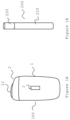
- FIG. 1B shows schematic view of the consumable article 200 according to the embodiment of the present invention.
- the consumable article 200 may be a stick or a tobacco stick comprising tobacco and/or other suitable substance that is heated but not burned in the heating compartment to create an inhalable aerosol.
- the consumable article 200 may further comprise a flavour adding substance.
- the consumable article 200 may have an elongated form, for example a cylindrical form as shown in figure 1B .
- the consumable article 200 may be partitioned in two parts: in the first part 210 the aerosol generating substance is placed while the second part is a filter portion 220.
- the consumable article 200 may further comprise a metal foil, for example aluminium foil. The metal foil may stop the consumable article 200 from being combustible.
- a system comprising the aerosol generating device 100 as described herein and the consumable article 200 as described herein comprise a system for generating an aerosol generating substance according to the embodiment of the present invention.
- the aerosol generating device 100 may comprise on the outer side of the housing portion 1 means 3 comprising one or more input means (comprising for example one or more buttons) for giving instructions to the aerosol generating device 100, for example instructions for outputting a battery level information, and/or one or more output means for indicating different information to the user, such as battery level information, possible error information and so on.
- the output means may be any suitable output means, for example a liquid crystal display (LCD display) or LED display, or one or more indicators, for example lamps or light emitting devices (LEDs).
- LCD display liquid crystal display
- LEDs light emitting devices
- the protection means 11 for exposing (or opening) and covering (or closing) an opening 13 to a heating compartment of the aerosol generating device 100 may comprise for example a slider 11 as shown schematically in figures 2A and 2B .
- the slider 11 may be moved, for example by sliding, between a first position and a second position so that the opening 13 of the heating compartment is covered when the slider is in the first position and exposed when the slider is in the second position.
- the slider 11 being in the first position is also be referred here below as the slider being closed and the slider 11 being in the second position is also be called here below as the slider 11 being opened.
- Figure 2A shows a schematic view of the aerosol generating device 100 with the heating compartment 10 according to the embodiment of the present invention when the slider 11 is in the first position so that the opening 13 is covered by the slider 11.
- Figure 2B shows a schematic view of the aerosol generating device 100 according to the embodiment of the present invention when the slider 11 is in the second position so that the opening 13 is exposed. When the opening 13 is exposed the user can insert the consumable article 200 in the heating compartment 10.
- the protection means 11 may comprise, for example, a cover lid or a trap door 11 that can at least partly be removed from the housing portion 12 as shown schematically in figures 3A and 3B .
- the cover lid, or trap door 11 is arranged to be movable between a first position and a second position so that the opening 13 of the heating compartment 10 (not shown in figure 3A and 3B ) is covered when the cover lid or the trap door 11 is in the first position and exposed when the cover lid or the trap door 11 is in the second position.
- Figure 3A shows a schematic view of the aerosol generating device 100 according to this embodiment of the present invention when the cover lid or trap door 11 is in the first position so that the opening 13 is covered by the cover lid or trap door 11.
- Figure 3B shows a schematic view of the aerosol generating device 100 according to this embodiment of the present invention when the cover lid or trap door 11 is in the second position so that the opening 13 is exposed. When the opening is exposed the user can insert the consumable article 200 in the heating compartment 10.
- the housing portion 1 of the aerosol generating device 100 may have a smooth outer surface which together with the elongated pebble-like shape provides a physical ergonomic advantage for the user.
- the housing portion 1 houses at least the mentioned heating compartment 10 and houses further components of the aerosol generating device 100 as elaborated below.
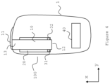
- Figure 4 shows schematically a cross-sectional view of the of the aerosol generating device 100 of the embodiment of the present invention along the elongated direction of the aerosol generating device 100.
- the housing portion 1 of the aerosol generating device 100 houses the heating compartment 10, also called here below a heating chamber or an oven.
- the heating compartment 10 may be such that the user can place one consumable article 200 at a time or the user may place more than one consumable articles 200 at a time in the heating compartment 10.
- the heating compartment 10 may also have an elongated cylindrical form as the consumable article 200 but may also have a different elongated form. The form of the consumable article 200 and the heating compartment 10 are not to be seen as limiting to the concept of the present invention.
- the heating compartment 10 extends along a first direction, which is denoted in figure 4 as x-direction.
- the first direction follows the elongated form of the aerosol generating device 100, or in other words, the aerosol generating device 100 is elongated along the first direction.
- the heating compartment 10 comprises a base portion 12 at a first end and the above-mentioned opening 13 at the second end.
- the opening 13 is opposite of the base portion 12.
- the heating compartment 10 comprises further one or more side walls.
- the heating compartment 10 comprises a cylindrical side wall when the form of the heating compartment 10 is the cylindrical form as mentioned above, or comprises a plurality of sidewalls when the form of the heating compartment 10 differs from the cylindrical form.
- the aerosol generating device 100 comprises further a heater 20 (or a heating arrangement 20 or a heating engine 20) for supplying heat to the heating compartment 10 to thereby heat the aerosol generating substance 210 in the consumable article 200 when inserted in the heating compartment.
- the heater 20 is also placed in the housing portion 1.
- the heater 20 may be a heater 20 that supplies heat to the heating compartment 10 based on a resistive heating, but may also be a heater 20 that supplies heat to the heating compartment 10 based on inductive heating.
- the type of heating is not to be seen as limiting to the concept of the present invention.
- the heater 20 is arranged outside the heating compartment 10 so that it indirectly, for example through convective heat transfer, heats the aerosol generating substance 210.
- Figure 4 shows the heater 20 as being arranged outside of the heating compartment 10 and extending along the first direction (the x-direction) from the base portion 12 of the heating compartment 10 towards the opening 13. In other words, figure 4 shows the heater 20 as extending along a side wall of the heating compartment 10. Further, the heater 20 may be arranged outwards of the heating compartment 10 on one side of the heating compartment 10, for example closer to the wall of the housing 1 or may be arranged on two opposite sides of the heating compartment 10 or may be wrapped around the heating compartment 10. In other embodiment of the present invention the heater 20 may be arranged at least partially in the heating compartment 10 and directly or indirectly heat the aerosol generating substance 210.
- the aerosol generating device 100 comprises further a detection means 31, 32 arranged outside the heating compartment 10 and configured to detect whether a consumable article 200 has been inserted in the heating compartment 10.
- the detection means 31, 32 are also arranged in the housing portion 1.
- the detection means 31, 32 comprise at least one hall sensor 31 and at least one magnet 32, said hall sensor 31 and said magnet 32 being arranged outside of the heating compartment 10.
- Figure 4 shows the hall sensor 31 and the heating compartment 33 as being arranged outwards of the heating compartment 10, on opposite sides of the heating compartment 10 in a second direction, denoted in the figure as y-direction, which is perpendicular to the first direction (x-direction).
- Figure 4 shows the hall sensor 31 as being arranged closer to the side wall of the housing 1 and the magnet 32 as being arranged on the opposite side of the heating compartment 10 in the second direction, however, the opposite arrangement is also possible, i.e.
- the magnet 32 is arranged closer to the sidewall of the housing 1 and the hall sensor 31 is arranged on the opposite side of the heating compartment 10 in the second direction. Further, figure 4 shows the hall sensor 31 and the magnet 32 as being arranged close to the base portion 12 of the heating compartment 10. However, in a different embodiment of the present invention the hall sensor 31 and the magnet 32 may be arranged further away from the base position 12 and towards the opening 13.
- the magnet 32 is a permanent magnet.
- the magnet 32 may be electromagnet, for example a coil which produces electromagnetic field when current is flowing through the coil.
- the hall sensor 31 may comprise a thin piece of, in general semiconductor material, through which a continuous electrical current is passed to generate a magnetic field.
- the magnetic flux exerts a force on the semiconductor material. This force causes a movement of electrons, creating a measurable hall voltage by the hall sensor.
- the output hall voltage from the hall sensor 31 is directly proportional to the strength of the magnetic field passing through the semiconductor material of the hall sensor 31.
- the consumable article 200 When the consumable article 200 is inserted in the heating compartment, it will weaken the magnetic field from the magnet 32 that is detected by the hall sensor 31. In other words, the inserted consumable article 200 will act as a shield to the magnetic field of the magnet 32 for the hall sensor 31 and hence the hall sensor 31 will detect a decreased strength of the magnetic field of the magnet 32 (drop in the magnetic field).
- the consumable article 200 comprises thin metal foil as elaborated above it will cause a greater drop in the magnetic field and hence it will be easier for the hall sensor 31 to detect the presence of the consumable article 200.
- the detection means 31, 32 may comprise a plurality of hall sensors 31 and a plurality of magnets 32.
- the plurality of hall sensors 31 and the plurality of magnets 32 are arranged in pairs such that in each pair, the hall sensor 31 and the magnet 32 are arranged outwards of the heating compartment 10 on opposite sides of the heating compartment 10 in the second direction which is perpendicular to the first direction.
- the different pairs are arranged along the first direction from the base portion of the heating compartment 10 towards the opening 13 of the heating compartment 10.
- the aerosol generating device 100 comprises further a power supply unit 40.
- the power supply unit 40 is also arranged in the housing portion 1.
- Figure 4 shows the power supply unit 40 as being arranged in the lower part of the aerosol generating device 100, however, the position of the power supply unit 40 is not to be seen as limiting to the present invention.
- the power supply unit 40 may be arranged in other parts of the aerosol generating device 100 for example sideward from the heating compartment 10.
- the power supply unit 40 may be a battery.
- the battery may be a rechargeable battery.
- the power supply unit 40 is configured to supply current to the heater 20.
- the power supply unit 40 is further configured to supply current to the hall sensor 31.
- the power supply unit 40 is further configured to supply current to the electromagnet.
- the aerosol generating device 100 comprises further a control unit (not shown in figure 4 ) for carrying out various processing as will be elaborated further below.
- the control unit is further configured for receiving signals as elaborated further below and for activating the supply of current from the power supply unit 40 to the heater 20 and/or the hall sensor 31 and/or the magnet 32 in the embodiment of the present invention in which the magnet 32 is an electromagnet.
- the control unit is also arranged in the housing portion 1.
- the control unit is any suitable unit or comprises any suitable unit such as computer processing unit that can perform computer processing.
- the control unit 50 also called controller
- the control unit 50 may be for example a micro processing unit (MCU).
- the control unit 50 may comprise storage means, such as a memory 60.
- the memory 60 may also be a separate unit from the control unit 50 also placed inside the housing portion 1.
- the memory 60 may store different information needed for the processing by the control unit 50, as will be elaborated further below.
- the memory may store computer program (code) comprising instructions which, when the program is executed by the control unit 50, cause the control unit 50 to carry out the processing of the embodiment of the present invention as will be elaborated further below.
- Figure 6 shows schematically the functional components of the aerosol generating device 100 of the embodiment of the present invention arranged in the housing portion 1. More specifically, figure 6 shows the aerosol generating device comprising the heating compartment 10, the heater 20, the detection means 30, the power supply unit 40, the control unit 50 and the memory 60.
- the protection means 11, as elaborated above, are arranged in the access portion 2.
- Figures 7A, 7B and 7C show schematically details of detecting the presence of the consumable article 200 by the aerosol generating device 100 according to the embodiment of the present invention.
- Figure 7A shows schematically a state of the aerosol generating device 100 in which the protection means 11 is in the first position, i.e. the opening 13 of the heating compartment 10 is covered (the protection means 11 is closed).
- the control unit 50 When the protection means 11 is moved from the first position to the second position so that the opening 13 of the heating compartment 12 is exposed (the protection means 11 is opened) the control unit 50 is configured to activate a supply of current from the power supply unit 40 to the hall sensor 31.
- the control unit 50 may be configured to activate a supply of current from the power supply unit 40 to the hall sensor 31 at a time point when the protection means 11 reaches the second position by being moved from the first position to the second position or at a pre-determined time after the time point when the protection means 11 reaches the second position by being moved from the first position to the second position.
- the access portion 2 of the aerosol generating device may comprise, as elaborated above, sensing means for sensing or determining the position of the protection means 11 and the like.
- sensing means for sensing or determining the position of the protection means 11 and the like.
- the sensing means may send a signal to the control unit 50.
- Figure 7B shows the aerosol generating device 1 in a state in which the protection means 11 is in the second position (the protection means is opened).
- the sensing means my send a signal to the control unit 50 at a time point at which the protection means 11 has reached the second position by being moved from the first position to the second position or at a pre-determined time after the time point when the protection means 11 reaches the second position by being moved from the first position to the second position.
- the signal may be sent also in any time point when movement of the protection means 11 from the first position towards the second position is sensed or detected by the sensing means.
- control unit 50 activates a supply of current from the power supply unit to the hall sensor 31.
- the hall sensor 31 measures the strength of the magnetic field of the magnet 32 when current is passed through the hall sensor 31 as elaborated above.
- the hall sensor 31 outputs a value, here below referred to as a first value, indicating said measured strength of the magnetic field to the control unit 50.
- the control unit 50 receives said first value from the hall sensor 31 and stores said first value in the memory 60.
- the hall sensor 31 continuously measures the strength of the magnetic field of the magnet 32 while the protection means 11 is in the second position and outputs a series of second values indicating the strength of the magnetic field to the control unit 50, each second value indicating the strength of the magnetic field in the corresponding measurement.
- the hall sensor 31 may be arranged to measure the strength of the magnetic field at predetermined time points after the time point at which the measurement for which the first value is obtained is carried out to thereby obtain a second value for each measurement and to output each second value to the control unit 50.
- the control unit 50 calculates a drop in the magnetic field based on the first value and the second value for each measurement. For example, the control unit 50 calculates the drop in the magnetic field by calculating the change from the first value to the second value in terms of percentage decrease. For this, the control unit 50 subtracts the second value from the first value to obtain the difference between the first value and the second value, divides the obtained difference between the first value and the second value with the first value and multiplies the result with 100 to thereby obtain the percentage decrease of the first value.
- the control unit 50 may also store each received second value and/or each determined percentage decrease in the memory 60.
- the control unit 50 When the control unit 50 detects that the percentage decrease of the first value has reached a pre-determined threshold, or in other words, the percentage decrease of the first value is equal to or higher than a pre-determined threshold (the drop in the magnetic field strength is at least x%, x being a predetermined value), the control unit 50 activates a supply of current from the power supply unit 40 to the heater 20.
- the pre-determined threshold may also be pre-stored in the memory 60.
- the hall sensor 31 continues with measuring the strength of the magnetic field of the magnet 32 and outputting said second value for each measurement to the control unit 50 as elaborated above.
- the control unit 50 may continue to determine the drop in the magnetic field of the magnet 32 as elaborated above. In this way, the control unit 50 may monitor the usage of the consumable article 200. In a different embodiment of the present invention the control unit 50 may also cease from determining the drop in the magnetic field after the supply of current to the heater 20 is activated.
- a signal is sent to the control unit 50 by the sensing means.
- the signal is sent to the control unit 50 at the time point when the protection means 11 reaches the first position by being moved from the second position to the first position or at a predetermined time after the time point when the protection means 11 reaches the first position by being moved from the second position to the first position.
- the control unit 50 turns off the supply of current to the hall sensor 31.
- the control unit 50 is configured to de-activate the supply of current to the hall sensor 31 when the protection means 11 is moved from the second position to the first position.
- the control unit 50 may be configured to delete the stored first value and any stored second values and percentage decrease values from the memory 60 in response to receiving the signal that the protection means 11 is moved in the first position from the second position.
- the heater 20 when it is detected that the consumable article 200 has been inserted in the heating compartment 10 the heater 20 is activated and hence the heating of the aerosol generating substance is started.
Landscapes
- Catching Or Destruction (AREA)
- Containers And Packaging Bodies Having A Special Means To Remove Contents (AREA)
Description
- The present invention relates to the field of aerosol generating devices and in particular relates to detection of consumable article in an aerosol generating device.
- In the recent years devices which heat rather than burn or cause combustion of a substance to generate a vapour or aerosol for inhalation by a user have become increasingly popular.
- Such commonly used devices which heat rather than burn or cause a combustion of a substance may be tobacco-based device also known as heated tobacco products. These devices normally use tobacco and/or other suitable substance that is heated but not burned to create an inhalable aerosol. The tobacco and/or the other suitable substance may in general also be called an aerosol generating substance and the device in general may be called an aerosol generating device.
- Normally, the aerosol generating substance is placed in a container, also called a stick or a tobacco stick, that can be inserted in and removed from the aerosol generating device by the user. Therefore, the stick or the tobacco stick is a consumable article.
- In general, the user inserts the consumable article in the heating compartment of the aerosol generating device. The heating compartment of the aerosol generating device may also be called a heating chamber or an oven. When the user has inserted the consumable article in the heating compartment the user normally turns on the heating of the aerosol generating device for example by operating an operation button or gives instruction by other means to the aerosol generating device for turning on the heating of the aerosol generating device so that the aerosol generating substance can be heated. The turning on of the heating of the aerosol generating substance may also be called a start of an aerosol generating session. Thereafter, the user waits until the heating has progressed to a state at which it is possible that the aerosol generating substance that is heated generates an aerosol that can be consumed by the user.
- This waiting time may be inconvenient for the user since normally the user likes to consume the aerosol as soon as possible after the consumable article is inserted in the heating compartment of the aerosol generating device. Even further, turning on the heating manually by the user requires providing an operation button or other means for giving an instruction to the aerosol generating device for turning on the heating of the aerosol generating substance which not only makes the structure of the aerosol generating device more complex but also reduces the convenience of the user in operating the aerosol generating device.
- Document
US 2021/015161 A1 relates to an apparatus for generating aerosol from an aerosolizable medium. The apparatus includes a housing; a chamber for receiving an article, a sensor and a cover system. The article includes an aerosolizable medium and a detectable element provided in association with the article. The sensor is configured to sense the detectable element when an article is received within the chamber. The cover system can be configured in at least a first configuration to substantially cover the sensor, and a second configuration, in which a field of view of the sensor is substantially without obstruction. - Document
WO 2020/225105 A1 relates to an aerosol generation device comprising a casing; an aperture in the casing through which aerosol generating material is insertable into the aerosol generation device; a closure moveable relative to the aperture between a closed position in which the closure covers the aperture, an open position in which the aperture is unobstructed by the closure, and an activation position that is different from the open position; and a detector arranged to detect movement of the closure from the closed position to the open position and between the open position and the activation position. - Therefore, there is a need for decreasing the time for generating an aerosol after the consumable article is inserted in the heating compartment of the aerosol generating device as well as for improving the user's convenience in operating the aerosol generating device and reducing the complexity of the aerosol generating device.
- The mentioned problems and objects are met by the subject-matter of the
independent claim 1. Advantageous embodiments are defined in the dependent claims. - According to one aspect of the present invention there is provided an aerosol generating device comprising: a heating compartment extending along a first direction and comprising a base portion at a first end and an opening opposite of the base portion and arranged so that a user can insert, via the opening, a consumable article containing an aerosol generating substance; protection means for exposing and covering said opening of the heating compartment, a heater configured to supply heat to the heating compartment to thereby heat the aerosol generating substance in the consumable article; and
a detection means arranged outside the heating compartment and configured to detect whether a consumable article has been inserted in the heating compartment, wherein the detection means comprises at least one hall sensor and at least one magnet, said hall sensor and said magnet being arranged outwards of the heating compartment on opposite sides of the heating compartment in a second direction which is perpendicular to the first direction. - According to a further aspect of the present invention there is provided a system comprising the aerosol generating device according to the previous aspect and a consumable article, said consumable comprising aerosol generating substance and a metal foil.
- Embodiments of the present invention which are presented for better understanding the inventive concept of the present invention, but which are not to be seen as limiting the present invention, will now be described with reference to the figures in which:
- Figs. 1A
- shows a schematic view of the aerosol generating device according to the embodiment of the present invention;
- Fig. 1B
- shows a schematic view of the consumable article to be used with the aerosol generating device according to the embodiment of the present invention;
- Fig. 2A and 2B
- show a schematic view of the aerosol generating device of the embodiment of the present invention;
- Fig. 3A and 3B
- show a schematic view of the aerosol generating device of other embodiment of the present invention;
- Fig. 4
- shows a schematic view of further details of the of the aerosol generating device of the embodiment of the present invention;
- Fig. 5
- shows a schematic view of further details of the of the aerosol generating device of other embodiment of the present invention;
- Fig. 6
- shows a schematic view of the functional components of the aerosol generating device of the embodiment of the present invention;
- Fig. 7A, 7B and 7C
- show a schematic view of the operation of the aerosol generating device according to the embodiment of the present invention.
-
Figure 1A shows a schematic view of the aerosol generatingdevice 100 according to the embodiment of the present invention. - The
aerosol generating device 100 according to the embodiment of the present invention is a handheld device with an elongated pebble-like shape and comprises ahousing portion 1 and anaccess portion 2. Theaccess portion 2 is in the top part of theaerosol generating device 100. Theaccess portion 2 comprises protection means 11 for exposing (or opening) and covering (or closing) anopening 13 to a heating compartment of theaerosol generating device 100. Theaccess portion 2 may further comprise other means, electrical or mechanical means, for moving or supporting the movement of the protection means 11, sensing (or determining) the position of the protection means 11 and the like. Such means for sensing (or determining) the position of the protection means 11 are also called here below sensing means. In the heating compartment, a user may place at least oneconsumable article 200 comprising an aerosol generating substance when theopening 13 is exposed. -
Figure 1B shows schematic view of theconsumable article 200 according to the embodiment of the present invention. Theconsumable article 200 may be a stick or a tobacco stick comprising tobacco and/or other suitable substance that is heated but not burned in the heating compartment to create an inhalable aerosol. Theconsumable article 200 may further comprise a flavour adding substance. Theconsumable article 200 may have an elongated form, for example a cylindrical form as shown infigure 1B . Theconsumable article 200 may be partitioned in two parts: in thefirst part 210 the aerosol generating substance is placed while the second part is afilter portion 220. In some embodiments of the present invention theconsumable article 200 may further comprise a metal foil, for example aluminium foil. The metal foil may stop theconsumable article 200 from being combustible. - A system comprising the
aerosol generating device 100 as described herein and theconsumable article 200 as described herein comprise a system for generating an aerosol generating substance according to the embodiment of the present invention. - As further shown in
figure 1A theaerosol generating device 100 may comprise on the outer side of thehousing portion 1 means 3 comprising one or more input means (comprising for example one or more buttons) for giving instructions to theaerosol generating device 100, for example instructions for outputting a battery level information, and/or one or more output means for indicating different information to the user, such as battery level information, possible error information and so on. The output means may be any suitable output means, for example a liquid crystal display (LCD display) or LED display, or one or more indicators, for example lamps or light emitting devices (LEDs). However, such input means and/or output means are to be seen as optional means that are by no way limiting to the present invention. - The protection means 11 for exposing (or opening) and covering (or closing) an
opening 13 to a heating compartment of theaerosol generating device 100 may comprise for example aslider 11 as shown schematically infigures 2A and 2B . Theslider 11 may be moved, for example by sliding, between a first position and a second position so that theopening 13 of the heating compartment is covered when the slider is in the first position and exposed when the slider is in the second position. Theslider 11 being in the first position is also be referred here below as the slider being closed and theslider 11 being in the second position is also be called here below as theslider 11 being opened. -
Figure 2A shows a schematic view of theaerosol generating device 100 with theheating compartment 10 according to the embodiment of the present invention when theslider 11 is in the first position so that theopening 13 is covered by theslider 11.Figure 2B shows a schematic view of theaerosol generating device 100 according to the embodiment of the present invention when theslider 11 is in the second position so that theopening 13 is exposed. When theopening 13 is exposed the user can insert theconsumable article 200 in theheating compartment 10. - In other embodiment of the present invention the protection means 11 may comprise, for example, a cover lid or a
trap door 11 that can at least partly be removed from thehousing portion 12 as shown schematically infigures 3A and 3B . The cover lid, ortrap door 11 is arranged to be movable between a first position and a second position so that theopening 13 of the heating compartment 10 (not shown infigure 3A and 3B ) is covered when the cover lid or thetrap door 11 is in the first position and exposed when the cover lid or thetrap door 11 is in the second position. -
Figure 3A shows a schematic view of theaerosol generating device 100 according to this embodiment of the present invention when the cover lid ortrap door 11 is in the first position so that theopening 13 is covered by the cover lid ortrap door 11.Figure 3B shows a schematic view of theaerosol generating device 100 according to this embodiment of the present invention when the cover lid ortrap door 11 is in the second position so that theopening 13 is exposed. When the opening is exposed the user can insert theconsumable article 200 in theheating compartment 10. - The
housing portion 1 of theaerosol generating device 100 may have a smooth outer surface which together with the elongated pebble-like shape provides a physical ergonomic advantage for the user. Thehousing portion 1 houses at least the mentionedheating compartment 10 and houses further components of theaerosol generating device 100 as elaborated below. -
Figure 4 shows schematically a cross-sectional view of the of theaerosol generating device 100 of the embodiment of the present invention along the elongated direction of theaerosol generating device 100. - As elaborated above the
housing portion 1 of theaerosol generating device 100 houses theheating compartment 10, also called here below a heating chamber or an oven. Theheating compartment 10 may be such that the user can place oneconsumable article 200 at a time or the user may place more than oneconsumable articles 200 at a time in theheating compartment 10. Theheating compartment 10 may also have an elongated cylindrical form as theconsumable article 200 but may also have a different elongated form. The form of theconsumable article 200 and theheating compartment 10 are not to be seen as limiting to the concept of the present invention. - The
heating compartment 10 extends along a first direction, which is denoted infigure 4 as x-direction. The first direction follows the elongated form of theaerosol generating device 100, or in other words, theaerosol generating device 100 is elongated along the first direction. Theheating compartment 10 comprises abase portion 12 at a first end and the above-mentionedopening 13 at the second end. Theopening 13 is opposite of thebase portion 12. Theheating compartment 10 comprises further one or more side walls. For example, theheating compartment 10 comprises a cylindrical side wall when the form of theheating compartment 10 is the cylindrical form as mentioned above, or comprises a plurality of sidewalls when the form of theheating compartment 10 differs from the cylindrical form. - The
aerosol generating device 100 comprises further a heater 20 (or aheating arrangement 20 or a heating engine 20) for supplying heat to theheating compartment 10 to thereby heat theaerosol generating substance 210 in theconsumable article 200 when inserted in the heating compartment. Theheater 20 is also placed in thehousing portion 1. Theheater 20 may be aheater 20 that supplies heat to theheating compartment 10 based on a resistive heating, but may also be aheater 20 that supplies heat to theheating compartment 10 based on inductive heating. The type of heating is not to be seen as limiting to the concept of the present invention. - In this embodiment of the present invention, the
heater 20 is arranged outside theheating compartment 10 so that it indirectly, for example through convective heat transfer, heats theaerosol generating substance 210.Figure 4 shows theheater 20 as being arranged outside of theheating compartment 10 and extending along the first direction (the x-direction) from thebase portion 12 of theheating compartment 10 towards theopening 13. In other words,figure 4 shows theheater 20 as extending along a side wall of theheating compartment 10. Further, theheater 20 may be arranged outwards of theheating compartment 10 on one side of theheating compartment 10, for example closer to the wall of thehousing 1 or may be arranged on two opposite sides of theheating compartment 10 or may be wrapped around theheating compartment 10. In other embodiment of the present invention theheater 20 may be arranged at least partially in theheating compartment 10 and directly or indirectly heat theaerosol generating substance 210. - The
aerosol generating device 100 comprises further a detection means 31, 32 arranged outside theheating compartment 10 and configured to detect whether aconsumable article 200 has been inserted in theheating compartment 10. The detection means 31, 32 are also arranged in thehousing portion 1. - The detection means 31, 32 comprise at least one
hall sensor 31 and at least onemagnet 32, saidhall sensor 31 and saidmagnet 32 being arranged outside of theheating compartment 10.Figure 4 shows thehall sensor 31 and the heating compartment 33 as being arranged outwards of theheating compartment 10, on opposite sides of theheating compartment 10 in a second direction, denoted in the figure as y-direction, which is perpendicular to the first direction (x-direction).Figure 4 shows thehall sensor 31 as being arranged closer to the side wall of thehousing 1 and themagnet 32 as being arranged on the opposite side of theheating compartment 10 in the second direction, however, the opposite arrangement is also possible, i.e. themagnet 32 is arranged closer to the sidewall of thehousing 1 and thehall sensor 31 is arranged on the opposite side of theheating compartment 10 in the second direction. Further,figure 4 shows thehall sensor 31 and themagnet 32 as being arranged close to thebase portion 12 of theheating compartment 10. However, in a different embodiment of the present invention thehall sensor 31 and themagnet 32 may be arranged further away from thebase position 12 and towards theopening 13. - In this embodiment of the present invention the
magnet 32 is a permanent magnet. In other embodiment of the present invention themagnet 32 may be electromagnet, for example a coil which produces electromagnetic field when current is flowing through the coil. - The
hall sensor 31 may comprise a thin piece of, in general semiconductor material, through which a continuous electrical current is passed to generate a magnetic field. When thehall sensor 31 is placed near themagnet 32, the magnetic flux exerts a force on the semiconductor material. This force causes a movement of electrons, creating a measurable hall voltage by the hall sensor. - The output hall voltage from the
hall sensor 31 is directly proportional to the strength of the magnetic field passing through the semiconductor material of thehall sensor 31. - When the
consumable article 200 is inserted in the heating compartment, it will weaken the magnetic field from themagnet 32 that is detected by thehall sensor 31. In other words, the insertedconsumable article 200 will act as a shield to the magnetic field of themagnet 32 for thehall sensor 31 and hence thehall sensor 31 will detect a decreased strength of the magnetic field of the magnet 32 (drop in the magnetic field). When theconsumable article 200 comprises thin metal foil as elaborated above it will cause a greater drop in the magnetic field and hence it will be easier for thehall sensor 31 to detect the presence of theconsumable article 200. - In a different embodiment of the present invention, as shown in
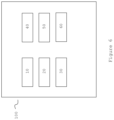
figure 5 , the detection means 31, 32 may comprise a plurality ofhall sensors 31 and a plurality ofmagnets 32. The plurality ofhall sensors 31 and the plurality ofmagnets 32 are arranged in pairs such that in each pair, thehall sensor 31 and themagnet 32 are arranged outwards of theheating compartment 10 on opposite sides of theheating compartment 10 in the second direction which is perpendicular to the first direction. The different pairs are arranged along the first direction from the base portion of theheating compartment 10 towards the opening 13 of theheating compartment 10. - The
aerosol generating device 100 comprises further apower supply unit 40. Thepower supply unit 40 is also arranged in thehousing portion 1.Figure 4 shows thepower supply unit 40 as being arranged in the lower part of theaerosol generating device 100, however, the position of thepower supply unit 40 is not to be seen as limiting to the present invention. In other words, in different embodiments of the present invention, thepower supply unit 40 may be arranged in other parts of theaerosol generating device 100 for example sideward from theheating compartment 10. Thepower supply unit 40 may be a battery. The battery may be a rechargeable battery. - The
power supply unit 40 is configured to supply current to theheater 20. Thepower supply unit 40 is further configured to supply current to thehall sensor 31. In embodiments of the present invention in which themagnet 32 is an electromagnet thepower supply unit 40 is further configured to supply current to the electromagnet. - The
aerosol generating device 100 comprises further a control unit (not shown infigure 4 ) for carrying out various processing as will be elaborated further below. The control unit is further configured for receiving signals as elaborated further below and for activating the supply of current from thepower supply unit 40 to theheater 20 and/or thehall sensor 31 and/or themagnet 32 in the embodiment of the present invention in which themagnet 32 is an electromagnet. The control unit is also arranged in thehousing portion 1. - The control unit is any suitable unit or comprises any suitable unit such as computer processing unit that can perform computer processing. The control unit 50 (also called controller) may be for example a micro processing unit (MCU). Further, the
control unit 50 may comprise storage means, such as amemory 60. Thememory 60 may also be a separate unit from thecontrol unit 50 also placed inside thehousing portion 1. Thememory 60 may store different information needed for the processing by thecontrol unit 50, as will be elaborated further below. Further, the memory may store computer program (code) comprising instructions which, when the program is executed by thecontrol unit 50, cause thecontrol unit 50 to carry out the processing of the embodiment of the present invention as will be elaborated further below. -
Figure 6 shows schematically the functional components of theaerosol generating device 100 of the embodiment of the present invention arranged in thehousing portion 1. More specifically,figure 6 shows the aerosol generating device comprising theheating compartment 10, theheater 20, the detection means 30, thepower supply unit 40, thecontrol unit 50 and thememory 60. The protection means 11, as elaborated above, are arranged in theaccess portion 2. -
Figures 7A, 7B and 7C show schematically details of detecting the presence of theconsumable article 200 by theaerosol generating device 100 according to the embodiment of the present invention. -
Figure 7A shows schematically a state of theaerosol generating device 100 in which the protection means 11 is in the first position, i.e. theopening 13 of theheating compartment 10 is covered (the protection means 11 is closed). - In this state, there is no current flowing through the
hall sensor 31 so that thehall sensor 31 is not detecting the strength of the magnetic field generated by themagnet 32. In other words, thecontrol unit 50 has not activated the supply of current from thepower supply unit 40 to thehall sensor 31. It is noted that even thoughfigure 7A (as well asfigures 7B and 7C ) shows the protection means 11 as comprising the slider elaborated above, the elaborations here apply also to the embodiment of the present invention in which the protection means 11 comprises the cover lid or a trap door as elaborated above. - When the protection means 11 is moved from the first position to the second position so that the
opening 13 of theheating compartment 12 is exposed (the protection means 11 is opened) thecontrol unit 50 is configured to activate a supply of current from thepower supply unit 40 to thehall sensor 31. For example, thecontrol unit 50 may be configured to activate a supply of current from thepower supply unit 40 to thehall sensor 31 at a time point when the protection means 11 reaches the second position by being moved from the first position to the second position or at a pre-determined time after the time point when the protection means 11 reaches the second position by being moved from the first position to the second position. - In the embodiment of the present invention the
access portion 2 of the aerosol generating device may comprise, as elaborated above, sensing means for sensing or determining the position of the protection means 11 and the like. When the sensing means senses or detects that the protection means 11 has reached the second position by being moved from the first position to the second position the sensing means may send a signal to thecontrol unit 50. -
Figure 7B shows theaerosol generating device 1 in a state in which the protection means 11 is in the second position (the protection means is opened). For example, the sensing means my send a signal to thecontrol unit 50 at a time point at which the protection means 11 has reached the second position by being moved from the first position to the second position or at a pre-determined time after the time point when the protection means 11 reaches the second position by being moved from the first position to the second position. - In a different embodiment of the present invention the signal may be sent also in any time point when movement of the protection means 11 from the first position towards the second position is sensed or detected by the sensing means.
- In response to the receiving of such signal, or in other words, triggered by the receiving of such signal, the
control unit 50 activates a supply of current from the power supply unit to thehall sensor 31. - Accordingly, the
hall sensor 31 measures the strength of the magnetic field of themagnet 32 when current is passed through thehall sensor 31 as elaborated above. Thehall sensor 31 outputs a value, here below referred to as a first value, indicating said measured strength of the magnetic field to thecontrol unit 50. Thecontrol unit 50 receives said first value from thehall sensor 31 and stores said first value in thememory 60. - The
hall sensor 31 continuously measures the strength of the magnetic field of themagnet 32 while the protection means 11 is in the second position and outputs a series of second values indicating the strength of the magnetic field to thecontrol unit 50, each second value indicating the strength of the magnetic field in the corresponding measurement. For example, thehall sensor 31 may be arranged to measure the strength of the magnetic field at predetermined time points after the time point at which the measurement for which the first value is obtained is carried out to thereby obtain a second value for each measurement and to output each second value to thecontrol unit 50. - The
control unit 50 calculates a drop in the magnetic field based on the first value and the second value for each measurement. For example, thecontrol unit 50 calculates the drop in the magnetic field by calculating the change from the first value to the second value in terms of percentage decrease. For this, thecontrol unit 50 subtracts the second value from the first value to obtain the difference between the first value and the second value, divides the obtained difference between the first value and the second value with the first value and multiplies the result with 100 to thereby obtain the percentage decrease of the first value. Thecontrol unit 50 may also store each received second value and/or each determined percentage decrease in thememory 60. - When the
control unit 50 detects that the percentage decrease of the first value has reached a pre-determined threshold, or in other words, the percentage decrease of the first value is equal to or higher than a pre-determined threshold (the drop in the magnetic field strength is at least x%, x being a predetermined value), thecontrol unit 50 activates a supply of current from thepower supply unit 40 to theheater 20. The pre-determined threshold may also be pre-stored in thememory 60. - As elaborated above, when the
consumable article 200 is inserted in theheating compartment 10 it will weaken the magnetic field from themagnet 32 that is detected by thehall sensor 31. This state of the aerosol generating device is shown schematically infigure 7C . In other word, the insertedconsumable article 200 acts as a shield to the magnetic field of themagnet 32 for thehall sensor 31 and therefore thehall sensor 31 measures lower strength of the magnetic field (the magnetic field is weakened). As elaborated above, this drop in the magnetic field being at least x% will trigger thecontrol unit 50 to turn on theheater 20 of theaerosol generating device 100 by activating a supply of current from thepower supply unit 40 to theheater 20. - After the supply of current to the
heater 20 is activated thehall sensor 31 continues with measuring the strength of the magnetic field of themagnet 32 and outputting said second value for each measurement to thecontrol unit 50 as elaborated above. Thecontrol unit 50 may continue to determine the drop in the magnetic field of themagnet 32 as elaborated above. In this way, thecontrol unit 50 may monitor the usage of theconsumable article 200. In a different embodiment of the present invention thecontrol unit 50 may also cease from determining the drop in the magnetic field after the supply of current to theheater 20 is activated. - When the protection means 11 is moved again in the first position from the second position, for example as being detected by the above-elaborated sensing means, a signal is sent to the
control unit 50 by the sensing means. For example, the signal is sent to thecontrol unit 50 at the time point when the protection means 11 reaches the first position by being moved from the second position to the first position or at a predetermined time after the time point when the protection means 11 reaches the first position by being moved from the second position to the first position. In response to receiving said signal thecontrol unit 50 turns off the supply of current to thehall sensor 31. Accordingly, thecontrol unit 50 is configured to de-activate the supply of current to thehall sensor 31 when the protection means 11 is moved from the second position to the first position. In addition, thecontrol unit 50 may be configured to delete the stored first value and any stored second values and percentage decrease values from thememory 60 in response to receiving the signal that the protection means 11 is moved in the first position from the second position. - In this way, it is enabled that the
heater 20 is turned on promptly when theconsumable article 200 is inserted in theaerosol generating device 100. Accordingly, it is not needed that the user turns on theheater 20 after having inserted theconsumable article 200 manually by operating an operation button or using other means for giving an instruction to theaerosol generating device 100 for turning on the heating of the aerosol generating substance. This improves the convenience of the user in using theaerosol generating device 100 and even further makes the structure of theaerosol generating device 100 less complex since it is not needed that an operation button or other means for giving an instruction to the aerosol generating device for turning on the heating of the aerosol generating substance are provided. Even further, since the detection means, i.e. thehall sensor 31 and themagnet 32 are arranged outside theheating compartment 10 it is enabled that they are protected of being damaged, for example by the user, when cleaning theheating compartment 10. - In summary, in the above-elaborated
aerosol generating device 100 when it is detected that theconsumable article 200 has been inserted in theheating compartment 10 theheater 20 is activated and hence the heating of the aerosol generating substance is started. - Although detailed embodiments have been described, these only serve to provide a better understanding of the invention defined by the appended claims and are not be seen as limiting.
Claims (13)
- An aerosol generating device (100) comprising:a heating compartment (10) extending along a first direction and comprising a base portion (12) at a first end and an opening (13) opposite of the base portion (12) and arranged so that a user can insert, via the opening (13), a consumable article (200) containing an aerosol generating substance (210);protection means (11) for exposing and covering said opening (13) of the heating compartment (10),a heater (20) configured to supply heat to the heating compartment (10) to thereby heat the aerosol generating substance (210) in the consumable article (200); anda detection means (31, 32) arranged outside the heating compartment (10) and configured to detect whether a consumable article (200) has been inserted in the heating compartment (10),wherein the detection means (31, 32) comprises at least one hall sensor (31) and at least one magnet (32),characterized in that said hall sensor (31) and said magnet (32) are arranged outwards of the heating compartment (10) on opposite sides of the heating compartment (10) in a second direction which is perpendicular to the first direction.
- The aerosol generating device (100) according to claim 1,
wherein the protection means (11) is arranged to be movable between a first position and a second position so that said opening (13) of the heating compartment (10) is covered when the protection means (11) is in the first position and exposed when the protection means (11) is in the second position. - The aerosol generating device (100) according to claim 1 or 2, further comprising:
a control unit (50) configured to activate a supply of current to the hall sensor (31) when the protecting means (11) is moved from the first position in the second position. - The aerosol generating device (100) according to claim 3,
wherein the hall sensor (31) is arranged to measure the strength of the magnetic field of the magnet (32) when the protecting means (11) is moved from the first position to the second position and to output a first value indicating said measured strength of the magnetic field to the control unit (50). - The aerosol generating device (100) according to claim 4,further comprising a memory (60),wherein the control unit (50) is configured to store said first value received from the hall sensor (31).
- The aerosol generating device (100) according to claim 4 or 5, wherein
the hall sensor (31) is configured to measure the strength of the magnetic field at a predetermined time point after the protecting means (11) is moved from the first position in the second position and to output a second value indicating said strength of the magnetic field to the control unit (50). - The aerosol generating device (100) according to claim 6,
wherein the control unit (50) is configured to calculate a percentage decrease of the first value with respect to the second value. - The aerosol generating device (10) according to claim 7,further comprising a power supply unit (40) configured to supply current to the heater (20), andthe control unit (50) is configured to activate a supply of current from the power supply unit (40) to the heater (20) when said percentage decrease is equal to or higher than a pre-determined threshold.
- The aerosol generating device (100) of claim 8, wherein the power supply (40) is further configured to supply current to the hall sensor (31).
- The aerosol generating device (100) according to any one of claims 1 to 9, wherein the control unit (50) is configured to de-activate the supply of current to the hall sensor (31) when the protection means (11) is moved from the second position to the first position.
- The aerosol generating device (100) according to any one of the claims 1 to 10, wherein the heater (20) is arranged outward of the heating compartment (10) and extends in the first direction from the bottom portion of the heating compartment (10) towards the opening (13) .
- The aerosol generating device (100) according to any one of the claims 1 to 11, wherein the detection means (31, 32) comprises a plurality of pairs of a hall sensor (31) and a magnet (32), wherein for each pair, said hall sensor (31) and said magnet (32) are arranged outwards of the heating compartment (10) on opposite sides of the heating compartment (10) in the second direction which is perpendicular to the first direction.
- A system comprising the aerosol generating device (100) according to any one of the preceding claims and a consumable article (200), said consumable (200) comprising aerosol generating substance (210) and a metal foil.
Applications Claiming Priority (2)
| Application Number | Priority Date | Filing Date | Title |
|---|---|---|---|
| EP21175238 | 2021-05-21 | ||
| PCT/EP2022/063597 WO2022243444A1 (en) | 2021-05-21 | 2022-05-19 | Aerosol generating device |
Publications (3)
| Publication Number | Publication Date |
|---|---|
| EP4340661A1 EP4340661A1 (en) | 2024-03-27 |
| EP4340661B1 true EP4340661B1 (en) | 2025-02-26 |
| EP4340661C0 EP4340661C0 (en) | 2025-02-26 |
Family
ID=76059719
Family Applications (1)
| Application Number | Title | Priority Date | Filing Date |
|---|---|---|---|
| EP22730731.1A Active EP4340661B1 (en) | 2021-05-21 | 2022-05-19 | Aerosol generating device |
Country Status (7)
| Country | Link |
|---|---|
| US (1) | US20240237715A1 (en) |
| EP (1) | EP4340661B1 (en) |
| JP (1) | JP2024518252A (en) |
| KR (1) | KR20240011692A (en) |
| CN (1) | CN117320581A (en) |
| PL (1) | PL4340661T3 (en) |
| WO (1) | WO2022243444A1 (en) |
Families Citing this family (1)
| Publication number | Priority date | Publication date | Assignee | Title |
|---|---|---|---|---|
| WO2025046701A1 (en) * | 2023-08-28 | 2025-03-06 | 日本たばこ産業株式会社 | Aerosol generation device |
Citations (14)
| Publication number | Priority date | Publication date | Assignee | Title |
|---|---|---|---|---|
| WO2015150759A1 (en) | 2014-03-31 | 2015-10-08 | Nicoventures Holdings Limited | Re-charging pack for an e-cigarette |
| CA3095452A1 (en) | 2018-03-29 | 2019-10-03 | Nicoventures Trading Limited | Apparatus for generating aerosol from an aerosolisable medium, an article of aerosolisable medium and a method of determining a parameter of an article |
| WO2019185748A1 (en) | 2018-03-29 | 2019-10-03 | Nicoventures Trading Limited | Apparatus for generating aerosol from an aerosolisable medium and article of aerosolisable medium |
| WO2019185749A1 (en) | 2018-03-29 | 2019-10-03 | Nicoventures Trading Limited | Apparatus for generating aerosol from an aerosolisable medium, an article of aerosolisable medium and a method of operating an aerosol generating apparatus |
| WO2019185746A1 (en) | 2018-03-29 | 2019-10-03 | Nicoventures Trading Limited | An aerosol delivery device, an article for use therewith, and a method of identifying an article |
| JP2019205405A (en) | 2018-05-30 | 2019-12-05 | 日本電産コパル株式会社 | Cigarette heating device |
| WO2020035587A1 (en) | 2018-08-17 | 2020-02-20 | Philip Morris Products S.A. | Aerosol-generating device for use with an aerosol-generating article comprising means for article identification |
| KR20200038050A (en) | 2018-10-02 | 2020-04-10 | 주식회사 이엠텍 | Fine particle generator |
| WO2020105896A1 (en) | 2018-11-23 | 2020-05-28 | 주식회사 케이티앤지 | Aerosol generating device and method for operating same |
| JP2020527053A (en) | 2017-10-30 | 2020-09-03 | ケイティー アンド ジー コーポレイション | Aerosol generator and its control method |
| WO2020222450A2 (en) | 2019-04-30 | 2020-11-05 | Kt&G Corporation | An aerosol generating device and an operation method thereof |
| CN112167712A (en) | 2019-07-02 | 2021-01-05 | 湖南中烟工业有限责任公司 | Normally closed type sliding dustproof door baking low-temperature smoking set and heating control method |
| US20210015161A1 (en) | 2018-03-29 | 2021-01-21 | Nicoventures Trading Limited | Apparatus for generation aerosol from an aerosolizable medium, an article of aerosolizable medium and a method of operating an aerosol generating apparatus |
| EP3599905B1 (en) * | 2017-03-24 | 2021-05-19 | Philip Morris Products S.A. | Methods and devices for cartridge authentication in electronic vaping devices or electronic cigarettes |
Family Cites Families (1)
| Publication number | Priority date | Publication date | Assignee | Title |
|---|---|---|---|---|
| EP3962301A1 (en) * | 2019-05-03 | 2022-03-09 | JT International SA | Aerosol generation device having a moveable closure with a detector |
-
2022
- 2022-05-19 CN CN202280035229.1A patent/CN117320581A/en active Pending
- 2022-05-19 US US18/563,094 patent/US20240237715A1/en active Pending
- 2022-05-19 JP JP2023560231A patent/JP2024518252A/en active Pending
- 2022-05-19 EP EP22730731.1A patent/EP4340661B1/en active Active
- 2022-05-19 PL PL22730731.1T patent/PL4340661T3/en unknown
- 2022-05-19 KR KR1020237039072A patent/KR20240011692A/en active Pending
- 2022-05-19 WO PCT/EP2022/063597 patent/WO2022243444A1/en not_active Ceased
Patent Citations (14)
| Publication number | Priority date | Publication date | Assignee | Title |
|---|---|---|---|---|
| WO2015150759A1 (en) | 2014-03-31 | 2015-10-08 | Nicoventures Holdings Limited | Re-charging pack for an e-cigarette |
| EP3599905B1 (en) * | 2017-03-24 | 2021-05-19 | Philip Morris Products S.A. | Methods and devices for cartridge authentication in electronic vaping devices or electronic cigarettes |
| JP2020527053A (en) | 2017-10-30 | 2020-09-03 | ケイティー アンド ジー コーポレイション | Aerosol generator and its control method |
| WO2019185749A1 (en) | 2018-03-29 | 2019-10-03 | Nicoventures Trading Limited | Apparatus for generating aerosol from an aerosolisable medium, an article of aerosolisable medium and a method of operating an aerosol generating apparatus |
| WO2019185746A1 (en) | 2018-03-29 | 2019-10-03 | Nicoventures Trading Limited | An aerosol delivery device, an article for use therewith, and a method of identifying an article |
| WO2019185748A1 (en) | 2018-03-29 | 2019-10-03 | Nicoventures Trading Limited | Apparatus for generating aerosol from an aerosolisable medium and article of aerosolisable medium |
| US20210015161A1 (en) | 2018-03-29 | 2021-01-21 | Nicoventures Trading Limited | Apparatus for generation aerosol from an aerosolizable medium, an article of aerosolizable medium and a method of operating an aerosol generating apparatus |
| CA3095452A1 (en) | 2018-03-29 | 2019-10-03 | Nicoventures Trading Limited | Apparatus for generating aerosol from an aerosolisable medium, an article of aerosolisable medium and a method of determining a parameter of an article |
| JP2019205405A (en) | 2018-05-30 | 2019-12-05 | 日本電産コパル株式会社 | Cigarette heating device |
| WO2020035587A1 (en) | 2018-08-17 | 2020-02-20 | Philip Morris Products S.A. | Aerosol-generating device for use with an aerosol-generating article comprising means for article identification |
| KR20200038050A (en) | 2018-10-02 | 2020-04-10 | 주식회사 이엠텍 | Fine particle generator |
| WO2020105896A1 (en) | 2018-11-23 | 2020-05-28 | 주식회사 케이티앤지 | Aerosol generating device and method for operating same |
| WO2020222450A2 (en) | 2019-04-30 | 2020-11-05 | Kt&G Corporation | An aerosol generating device and an operation method thereof |
| CN112167712A (en) | 2019-07-02 | 2021-01-05 | 湖南中烟工业有限责任公司 | Normally closed type sliding dustproof door baking low-temperature smoking set and heating control method |
Non-Patent Citations (2)
| Title |
|---|
| D7 - HONEYWELL: "Hall Effect Sensing And Application - Micro Switch Sensing And Control", 1998, pages: 1 - 127 |
| D8 - EDWARD RAMSDEN: "Hall Effect Sensors (Second Edition), Theory and Applications", 2006, ELSEVIER, ISBN: 978-0-7506-7934-3, pages: 1 - 296 |
Also Published As
| Publication number | Publication date |
|---|---|
| PL4340661T3 (en) | 2025-06-23 |
| KR20240011692A (en) | 2024-01-26 |
| EP4340661C0 (en) | 2025-02-26 |
| EP4340661A1 (en) | 2024-03-27 |
| WO2022243444A1 (en) | 2022-11-24 |
| JP2024518252A (en) | 2024-05-01 |
| CN117320581A (en) | 2023-12-29 |
| US20240237715A1 (en) | 2024-07-18 |
Similar Documents
| Publication | Publication Date | Title |
|---|---|---|
| KR102467839B1 (en) | Aerosol generating apparatus performing heating operation automatically | |
| JP7783319B2 (en) | Aerosol Delivery Device | |
| JP2022058533A5 (en) | ||
| US11969018B2 (en) | Aerosol generation device | |
| KR20230019912A (en) | Aerosol generating device including display | |
| CN115279217B (en) | Aerosol Generating Device Battery Monitoring | |
| KR20220002979A (en) | Aerosol-generating device with removable stopper with detector | |
| EP4340661B1 (en) | Aerosol generating device | |
| KR20200127892A (en) | Portable aerosol generator | |
| JP7248366B2 (en) | Aerosol-generating devices, aerosol-generating articles, and methods of determining data associated with aerosol-generating articles | |
| EP4344349A1 (en) | Vapour generating device | |
| EP4426146B1 (en) | Temperature measurement system for an aerosol-generating device, aerosol-generating device comprising the temperature measurement system and method for measuring a temperature in an aerosol-generating device | |
| KR102807242B1 (en) | Aerosol generator with door open judgment function | |
| KR102832996B1 (en) | Aerosol generating device | |
| KR20240142415A (en) | suction device | |
| US20240415192A1 (en) | Aerosol generating device and controlling method of aerosol generating device | |
| US20240251860A1 (en) | Aerosol provision device | |
| US20240415193A1 (en) | Aerosol generating device and operating method thereof | |
| KR20250039676A (en) | Aerosol generating device | |
| CN120751948A (en) | Aerosol generating device | |
| WO2025036812A1 (en) | Aerosol-generating article and system | |
| KR20250034802A (en) | Aerosol generating device | |
| KR20240177296A (en) | Aerosol generating device and operating method thereof | |
| KR20250039675A (en) | Aerosol generating device | |
| KR20250002904A (en) | Aerosol-generating device with cigarette insertion detecting |
Legal Events
| Date | Code | Title | Description |
|---|---|---|---|
| STAA | Information on the status of an ep patent application or granted ep patent |
Free format text: STATUS: UNKNOWN |
|
| STAA | Information on the status of an ep patent application or granted ep patent |
Free format text: STATUS: THE INTERNATIONAL PUBLICATION HAS BEEN MADE |
|
| PUAI | Public reference made under article 153(3) epc to a published international application that has entered the european phase |
Free format text: ORIGINAL CODE: 0009012 |
|
| STAA | Information on the status of an ep patent application or granted ep patent |
Free format text: STATUS: REQUEST FOR EXAMINATION WAS MADE |
|
| 17P | Request for examination filed |
Effective date: 20231214 |
|
| AK | Designated contracting states |
Kind code of ref document: A1 Designated state(s): AL AT BE BG CH CY CZ DE DK EE ES FI FR GB GR HR HU IE IS IT LI LT LU LV MC MK MT NL NO PL PT RO RS SE SI SK SM TR |
|
| DAV | Request for validation of the european patent (deleted) | ||
| DAX | Request for extension of the european patent (deleted) | ||
| GRAP | Despatch of communication of intention to grant a patent |
Free format text: ORIGINAL CODE: EPIDOSNIGR1 |
|
| STAA | Information on the status of an ep patent application or granted ep patent |
Free format text: STATUS: GRANT OF PATENT IS INTENDED |
|
| INTG | Intention to grant announced |
Effective date: 20240923 |
|
| GRAS | Grant fee paid |
Free format text: ORIGINAL CODE: EPIDOSNIGR3 |
|
| GRAA | (expected) grant |
Free format text: ORIGINAL CODE: 0009210 |
|
| STAA | Information on the status of an ep patent application or granted ep patent |
Free format text: STATUS: THE PATENT HAS BEEN GRANTED |
|
| AK | Designated contracting states |
Kind code of ref document: B1 Designated state(s): AL AT BE BG CH CY CZ DE DK EE ES FI FR GB GR HR HU IE IS IT LI LT LU LV MC MK MT NL NO PL PT RO RS SE SI SK SM TR |
|
| REG | Reference to a national code |
Ref country code: GB Ref legal event code: FG4D |
|
| REG | Reference to a national code |
Ref country code: CH Ref legal event code: EP |
|
| REG | Reference to a national code |
Ref country code: DE Ref legal event code: R096 Ref document number: 602022011187 Country of ref document: DE |
|
| REG | Reference to a national code |
Ref country code: IE Ref legal event code: FG4D |
|
| U01 | Request for unitary effect filed |
Effective date: 20250320 |
|
| U07 | Unitary effect registered |
Designated state(s): AT BE BG DE DK EE FI FR IT LT LU LV MT NL PT RO SE SI Effective date: 20250326 |
|
| U20 | Renewal fee for the european patent with unitary effect paid |
Year of fee payment: 4 Effective date: 20250528 |
|
| PG25 | Lapsed in a contracting state [announced via postgrant information from national office to epo] |
Ref country code: RS Free format text: LAPSE BECAUSE OF FAILURE TO SUBMIT A TRANSLATION OF THE DESCRIPTION OR TO PAY THE FEE WITHIN THE PRESCRIBED TIME-LIMIT Effective date: 20250526 |
|
| PGFP | Annual fee paid to national office [announced via postgrant information from national office to epo] |
Ref country code: PL Payment date: 20250512 Year of fee payment: 4 |
|
| PG25 | Lapsed in a contracting state [announced via postgrant information from national office to epo] |
Ref country code: ES Free format text: LAPSE BECAUSE OF FAILURE TO SUBMIT A TRANSLATION OF THE DESCRIPTION OR TO PAY THE FEE WITHIN THE PRESCRIBED TIME-LIMIT Effective date: 20250226 |
|
| PG25 | Lapsed in a contracting state [announced via postgrant information from national office to epo] |
Ref country code: NO Free format text: LAPSE BECAUSE OF FAILURE TO SUBMIT A TRANSLATION OF THE DESCRIPTION OR TO PAY THE FEE WITHIN THE PRESCRIBED TIME-LIMIT Effective date: 20250526 Ref country code: IS Free format text: LAPSE BECAUSE OF FAILURE TO SUBMIT A TRANSLATION OF THE DESCRIPTION OR TO PAY THE FEE WITHIN THE PRESCRIBED TIME-LIMIT Effective date: 20250626 |
|
| PG25 | Lapsed in a contracting state [announced via postgrant information from national office to epo] |
Ref country code: HR Free format text: LAPSE BECAUSE OF FAILURE TO SUBMIT A TRANSLATION OF THE DESCRIPTION OR TO PAY THE FEE WITHIN THE PRESCRIBED TIME-LIMIT Effective date: 20250226 |
|
| PG25 | Lapsed in a contracting state [announced via postgrant information from national office to epo] |
Ref country code: GR Free format text: LAPSE BECAUSE OF FAILURE TO SUBMIT A TRANSLATION OF THE DESCRIPTION OR TO PAY THE FEE WITHIN THE PRESCRIBED TIME-LIMIT Effective date: 20250527 |
|
| PGFP | Annual fee paid to national office [announced via postgrant information from national office to epo] |
Ref country code: CH Payment date: 20250601 Year of fee payment: 4 |
|
| PG25 | Lapsed in a contracting state [announced via postgrant information from national office to epo] |
Ref country code: SM Free format text: LAPSE BECAUSE OF FAILURE TO SUBMIT A TRANSLATION OF THE DESCRIPTION OR TO PAY THE FEE WITHIN THE PRESCRIBED TIME-LIMIT Effective date: 20250226 |
|
| PG25 | Lapsed in a contracting state [announced via postgrant information from national office to epo] |
Ref country code: CZ Free format text: LAPSE BECAUSE OF FAILURE TO SUBMIT A TRANSLATION OF THE DESCRIPTION OR TO PAY THE FEE WITHIN THE PRESCRIBED TIME-LIMIT Effective date: 20250226 |
|
| PG25 | Lapsed in a contracting state [announced via postgrant information from national office to epo] |
Ref country code: SK Free format text: LAPSE BECAUSE OF FAILURE TO SUBMIT A TRANSLATION OF THE DESCRIPTION OR TO PAY THE FEE WITHIN THE PRESCRIBED TIME-LIMIT Effective date: 20250226 |
|
| PLBI | Opposition filed |
Free format text: ORIGINAL CODE: 0009260 |