EP4340386B1 - Piezoelectric module - Google Patents
Piezoelectric module Download PDFInfo
- Publication number
- EP4340386B1 EP4340386B1 EP21963478.9A EP21963478A EP4340386B1 EP 4340386 B1 EP4340386 B1 EP 4340386B1 EP 21963478 A EP21963478 A EP 21963478A EP 4340386 B1 EP4340386 B1 EP 4340386B1
- Authority
- EP
- European Patent Office
- Prior art keywords
- piezoelectric
- module
- sot
- piezoelectric elements
- elastic bodies
- Prior art date
- Legal status (The legal status is an assumption and is not a legal conclusion. Google has not performed a legal analysis and makes no representation as to the accuracy of the status listed.)
- Active
Links
Images











Classifications
-
- H—ELECTRICITY
- H04—ELECTRIC COMMUNICATION TECHNIQUE
- H04R—LOUDSPEAKERS, MICROPHONES, GRAMOPHONE PICK-UPS OR LIKE ACOUSTIC ELECTROMECHANICAL TRANSDUCERS; ELECTRIC HEARING AIDS; PUBLIC ADDRESS SYSTEMS
- H04R17/00—Piezoelectric transducers; Electrostrictive transducers
-
- G—PHYSICS
- G10—MUSICAL INSTRUMENTS; ACOUSTICS
- G10K—SOUND-PRODUCING DEVICES; METHODS OR DEVICES FOR PROTECTING AGAINST, OR FOR DAMPING, NOISE OR OTHER ACOUSTIC WAVES IN GENERAL; ACOUSTICS NOT OTHERWISE PROVIDED FOR
- G10K9/00—Devices in which sound is produced by vibrating a diaphragm or analogous element, e.g. fog horns, vehicle hooters or buzzers
- G10K9/12—Devices in which sound is produced by vibrating a diaphragm or analogous element, e.g. fog horns, vehicle hooters or buzzers electrically operated
- G10K9/122—Devices in which sound is produced by vibrating a diaphragm or analogous element, e.g. fog horns, vehicle hooters or buzzers electrically operated using piezoelectric driving means
-
- H—ELECTRICITY
- H04—ELECTRIC COMMUNICATION TECHNIQUE
- H04R—LOUDSPEAKERS, MICROPHONES, GRAMOPHONE PICK-UPS OR LIKE ACOUSTIC ELECTROMECHANICAL TRANSDUCERS; ELECTRIC HEARING AIDS; PUBLIC ADDRESS SYSTEMS
- H04R1/00—Details of transducers, loudspeakers or microphones
- H04R1/02—Casings; Cabinets ; Supports therefor; Mountings therein
-
- H—ELECTRICITY
- H04—ELECTRIC COMMUNICATION TECHNIQUE
- H04R—LOUDSPEAKERS, MICROPHONES, GRAMOPHONE PICK-UPS OR LIKE ACOUSTIC ELECTROMECHANICAL TRANSDUCERS; ELECTRIC HEARING AIDS; PUBLIC ADDRESS SYSTEMS
- H04R17/00—Piezoelectric transducers; Electrostrictive transducers
- H04R17/005—Piezoelectric transducers; Electrostrictive transducers using a piezoelectric polymer
-
- H—ELECTRICITY
- H04—ELECTRIC COMMUNICATION TECHNIQUE
- H04R—LOUDSPEAKERS, MICROPHONES, GRAMOPHONE PICK-UPS OR LIKE ACOUSTIC ELECTROMECHANICAL TRANSDUCERS; ELECTRIC HEARING AIDS; PUBLIC ADDRESS SYSTEMS
- H04R7/00—Diaphragms for electromechanical transducers; Cones
- H04R7/02—Diaphragms for electromechanical transducers; Cones characterised by the construction
- H04R7/04—Plane diaphragms
- H04R7/045—Plane diaphragms using the distributed mode principle, i.e. whereby the acoustic radiation is emanated from uniformly distributed free bending wave vibration induced in a stiff panel and not from pistonic motion
-
- G—PHYSICS
- G10—MUSICAL INSTRUMENTS; ACOUSTICS
- G10K—SOUND-PRODUCING DEVICES; METHODS OR DEVICES FOR PROTECTING AGAINST, OR FOR DAMPING, NOISE OR OTHER ACOUSTIC WAVES IN GENERAL; ACOUSTICS NOT OTHERWISE PROVIDED FOR
- G10K2210/00—Details of active noise control [ANC] covered by G10K11/178 but not provided for in any of its subgroups
- G10K2210/10—Applications
- G10K2210/105—Appliances, e.g. washing machines or dishwashers
-
- G—PHYSICS
- G10—MUSICAL INSTRUMENTS; ACOUSTICS
- G10K—SOUND-PRODUCING DEVICES; METHODS OR DEVICES FOR PROTECTING AGAINST, OR FOR DAMPING, NOISE OR OTHER ACOUSTIC WAVES IN GENERAL; ACOUSTICS NOT OTHERWISE PROVIDED FOR
- G10K2210/00—Details of active noise control [ANC] covered by G10K11/178 but not provided for in any of its subgroups
- G10K2210/10—Applications
- G10K2210/128—Vehicles
- G10K2210/1282—Automobiles
-
- H—ELECTRICITY
- H04—ELECTRIC COMMUNICATION TECHNIQUE
- H04R—LOUDSPEAKERS, MICROPHONES, GRAMOPHONE PICK-UPS OR LIKE ACOUSTIC ELECTROMECHANICAL TRANSDUCERS; ELECTRIC HEARING AIDS; PUBLIC ADDRESS SYSTEMS
- H04R2440/00—Bending wave transducers covered by H04R, not provided for in its groups
- H04R2440/01—Acoustic transducers using travelling bending waves to generate or detect sound
-
- H—ELECTRICITY
- H04—ELECTRIC COMMUNICATION TECHNIQUE
- H04R—LOUDSPEAKERS, MICROPHONES, GRAMOPHONE PICK-UPS OR LIKE ACOUSTIC ELECTROMECHANICAL TRANSDUCERS; ELECTRIC HEARING AIDS; PUBLIC ADDRESS SYSTEMS
- H04R2440/00—Bending wave transducers covered by H04R, not provided for in its groups
- H04R2440/05—Aspects relating to the positioning and way or means of mounting of exciters to resonant bending wave panels
-
- H—ELECTRICITY
- H04—ELECTRIC COMMUNICATION TECHNIQUE
- H04R—LOUDSPEAKERS, MICROPHONES, GRAMOPHONE PICK-UPS OR LIKE ACOUSTIC ELECTROMECHANICAL TRANSDUCERS; ELECTRIC HEARING AIDS; PUBLIC ADDRESS SYSTEMS
- H04R2499/00—Aspects covered by H04R or H04S not otherwise provided for in their subgroups
- H04R2499/10—General applications
- H04R2499/13—Acoustic transducers and sound field adaptation in vehicles
Definitions
- Patent Document 2 describes a piezoelectric oscillation unit including a rectangular first conductor plate; a support portion for supporting the opposite ends of the first conductor plate in the longitudinal direction; a planar piezoelectric element fixed to at least one principal surface of the first conductor plate; a first coupling portion formed on at least a part of one side face of the first conductor plate parallel with the longitudinal direction; a second coupling portion formed on at least a part of the other side face of the first conductor plate parallel with the longitudinal direction; a first weight connecting with the first coupling portion; and a second weight connecting with the second coupling portion.
- Patent Document 3 describes a small-size thin piezoelectric actuator mountable on a mobile electronic device to give a contact feeling of a three dimensional movement to a user's hand palm.
- the piezoelectric actuator comprises a piezoelectric ceramic oscillator having a piezoelectric ceramic thin plate bonded to at least one surface of a shim member, at least one holder for holding the shim member, and a sheet-shaped elastic body.
- the piezoelectric module can be applied not only to speakers for watching television programs, movies, music, and the like, but also to various applications.
- a piezoelectric module that can obtain sufficient sound pressure in the low and middle audio frequency range is available for a loudspeaker and noise canceller, even if it does not have an acoustic structure such as a hole and cavity, as long as it has a vibration plate .
- Such a piezoelectric module has the potential to be quite different from a conventional piezoelectric module and should be referred to as a SoT (Sound of Things) module (hereinafter, piezoelectric modules that can improve sound pressure in a particular audio frequency range are referred to as a SoT module).
- SoT Sound of Things
- the inventors of the present invention have continued trial and error in the development of a piezoelectric module by which sufficient sound pressure is obtained even in the low and middle audio frequency range.
- the piezoelectric element 2110 is provided with a central portion supported by the elastic body 2120.
- various materials have been tried.
- the present invention has been made in view of such circumstances, a SoT module that generates sufficient sound pressure in the low and middle audio frequency range and can be applied to a variety of applications is provided.
- a piezoelectric module comprises a plate-shaped piezoelectric composite for generating bending vibration by the impression of an AC voltage, a plurality of elastic bodies, one ends of which are bonded to a main surface of the piezoelectric composite, the elastic bodies transmitting vibration of the piezoelectric composite, and a vibration plate having a main surface which is bonded to other ends of the elastic bodies, wherein the piezoelectric composite comprises a piezoelectric element formed in a rectangular plate, there is a position of a centroid of the piezoelectric composite between the plurality of elastic bodies, and the piezoelectric composite comprises a plurality of piezoelectric elements, each of which is identical to the piezoelectric element, and each of the piezoelectric elements is partially connected to each other.
- the stiffness of the entire module can be reduced, and the displacement amplitude of the vibration plate can be increased.
- sufficient sound pressure is obtained in the low and middle audio frequency range, and it can be applied to various applications.
- Fig. 1 is a perspective view showing a SoT module 100.
- the SoT module 100 comprises piezoelectric elements 110a and 110b, elastic bodies 120a and 120b and a vibration plate 130.
- Each of the piezoelectric elements 110a and 110b is formed bending-type in a rectangular plate and generates flexural vibration by impression of an AC voltage.
- the piezoelectric elements 110a and 110b are arranged in parallel and are not connected to each other. Between the elastic bodies 120a and 120b is the position of the centroid of each of the piezoelectric elements 110a and 110b. As a result, sufficient sound pressure is obtained in the low and middle audio frequency range, SoT module 100 can be applied to a variety of applications. Each of the piezoelectric elements 110a and 110b configures a piezoelectric composite.
- Fig. 2 is a cross-sectional view showing an example of the configuration and operation of the piezoelectric element 110.
- the piezoelectric element 110 is an example of the configuration of the piezoelectric elements 110a and 110b.
- the piezoelectric element 110 comprises piezoelectric bodies 111 and 112, electrodes 113 and 114 and shim plate 115.
- the shim plate 115 is made of metal and also has the function of an electrode.
- the piezoelectric bodies 111 and 112 are preferably formed of a piezoelectric ceramic material.
- the piezoelectric material for example, zirconate titanate (Pb(Ti, Zr)O 3 , so-called PZT) or barium titanate (BaTiO 3 ) is used. Both are ferroelectrics, and PZT is preferable from the viewpoint of efficiency, but barium titanate is preferable from the viewpoint of lead-free.
- the piezoelectric bodies 111 and 112 may be formed of a piezoelectric polymer. Piezoelectric polymers comprise polyvinylidene fluoride and copolymers thereof, polylactic acid, polyvinylidene cyanide, polyurea and odd nylon.
- Piezoelectric body 111 is polarized in the direction of the shim plate 115 from the electrode 113
- the piezoelectric body 112 is polarized in the direction of the electrode 114 from the shim plate 115.
- One electrode is connected to the electrodes 113 and 114
- the other electrode is connected to the shim plate 115.
- the above-described piezoelectric element 110 has a parallel bimorph structure in which the polarization directions of the piezoelectric bodies 111 and 112 are the same but may have a series bimorph structure in which the polarization directions are different. Further, an insulator may be used for the central shim plate.
- the piezoelectric element 110 preferably has a bimorph structure but may have a unimorph structure.
- a piezoelectric multilayer body may be used in place of the piezoelectric body of a single plate. In this case, an external electrode may be used, or an electrode may be formed by a via structure. Further, the piezoelectric element 110 is formed by the piezoelectric layer and the electrode being stacked, it may be a stretching-type piezoelectric element which expands and contracts in the stacking direction.
- the elastic body 120a has one end bonded to the main surface of the piezoelectric element 110a and the other end bonded to the main surface of the vibration plate 130, and the elastic body120b has one end bonded to the main surface of the piezoelectric element 110b and the other end bonded to the main surface of the vibration plate 130.
- an epoxy-based, acrylic-based, or urethane-based adhesive can be used for bonding (hereinafter, for any bonding is the same) .
- the elastic bodies 120a and 120b are preferably formed of a resin such as urethane.
- the elastic modulus of the elastic bodies 120a and 120b is preferably 70MPa or more and 690MPa or less.
- the elastic bodies 120a and 120b transmit the displacement of the piezoelectric elements 110a and 110b to the vibration plate 130.
- the position of the centroid for each of the piezoelectric elements 110a and 110b is preferably located.
- the stiffness of the entire SoT module 100 can be reduced, and the peak dip in the middle audio frequency range occurred for the piezoelectric elements 110a and 110b in which the natural frequency is set to be small can be eliminated.
- the elastic bodies 120a and 120b are bonded to respective ends of the piezoelectric elements 110a and 110b.
- the region can be divided into a central portion, two intermediate portions, and two end portions.
- Each of the elastic bodies 120a and 120b is preferably formed in a rectangular shape as shown in Fig. 1 but may be formed in a cylindrical shape or an elliptical cylindrical shape.
- the elastic bodies 120a, 120b are preferably symmetrical in shape and arrangement with respect to the piezoelectric elements 110a, 110b to be bonded.
- the vibration plate 130 is formed in a plate shape and bonded to the elastic bodies 120a and 120b.
- the material of the vibration plate 130 varies depending on the application.
- a styrene board can be used as the vibration plate 130.
- the vibration plate 130 made of resin is easily used, a vibration plate with inelasticity enhanced using wood or fiber structure may be used.
- the vibration plate 130 vibrates in the thickness direction by the displacement force transmitted through the elastic bodies 120a and 120b, vibrates air and generates sound waves.
- the pitch and the sound pressure of the sound generated from the vibration plate 130 appear differently for magnitude. In order to generate a large sound pressure, it is effective to improve the efficiency of vibration which is connected to the vibration plate.
- the SoT module 100 By the electrical signal for the sound amplified by the amplifier being input to the SoT module 100, the piezoelectric composite 105 vibrates. Then, the displacement due to the vibration is transmitted to the vibration plate 130 via the elastic bodies 120a and 120b, and the vibration plate 130 vibrates to generate a sound corresponding to the electric signal.
- the unconnected piezoelectric elements 110a and 110b are preferably driven in anti-phase or in-phase.
- the stiffness of the whole path transmitted by vibration and a combination of the phase driving each piezoelectric element is determined according to the required characteristics such as the sound pressure in the low audio frequency range.
- the stiffness of the whole path is determined by each element. For example, even when the stiffness of the piezoelectric elements 110a and 110b and the vibration plate 130 is large, when the stiffness of the elastic bodies 120a and 120b is small, the stiffness of the whole path may be small.
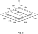
- FIG. 3 is a perspective view showing the SoT module 200.
- the SoT module 200 comprises piezoelectric elements 210a and 210b, elastic bodies 220a and 220b, connecting members 240a and 240b and a vibration plate 130.
- the piezoelectric elements 210a and 210b have the same configuration as the piezoelectric elements 110a and 110b, respectively.
- the piezoelectric elements 210a and 210b are provided in parallel with each other on the vibration plate 130, and a part of each other is connected to configure a plate-shaped piezoelectric composite 205.
- the vibration is amplified through the connecting portion, the displacement amplitude of the vibration plate 130 can be increased.
- Each of the elastic bodies 220a and 220b is formed of the same material in a rectangular plate shape and arranged as each of the elastic bodies 120a and 120b.
- Each of the two connecting members 240a and 240b is formed of resin such as PET in a flat plate shape and connects the end of the piezoelectric element 210a and the end of the piezoelectric element 210b.
- the connecting is performed by bonding the back surfaces of the connecting members 240a and 240b and the surfaces of the piezoelectric elements 210a and 210b to each other.
- the connecting members 240a and 240b are arranged so that their longitudinal directions do not intersect each other and are preferably parallel to each other.
- the thickness of the connecting members 240a and 240b is designed according to the overall configuration, for example, 100 ⁇ m or more and 1000um or less.
- the piezoelectric elements 210a and 210b and the connecting members 240a and 240b configure the piezoelectric composite 205.
- the electrodes of the piezoelectric elements 210a and 210b are omitted.
- the piezoelectric elements 210a and 210b are wired so as to be driven in in-phase or anti-phase to each other. That is, the piezoelectric elements 210a and 210b are wired so as to be driven in in-phase or anti-phase, and electric signals are input thereto.
- vibration of the piezoelectric elements 210a and 210b can be amplified via the connecting members 240a and 240b, and the sound pressure in the low audio frequency range to the middle audio frequency range can be improved.
- Either in-phase or anti-phase may be selected depending on the combination of the required characteristics and the stiffness of the whole path transmitted by the vibration.
- the piezoelectric elements 210a and 210b are wired so as to be driven in anti-phase to each other, and electric signals can be input.
- the respective piezoelectric elements 210a and 210b are driven in anti-phases with respect to the SoT module 200 in which the piezoelectric composite 205 is located on the upper side and the vibration plate 130 is located on the lower side. In this case, when the central portion of the piezoelectric element 210a is displaced downward, the central portion of the piezoelectric element 210b is displaced upward.
- the piezoelectric elements 210a and 210b may be wired so as to be driven in phase with each other, and electric signals may be input.
- each piezoelectric element is driven in phase, when the center portion of the piezoelectric element 210a is displaced downward, the center portion of the piezoelectric element 210b is also displaced downward.
- the central portion of the piezoelectric element 210a is displaced upward, the central portion of the piezoelectric element 210b is also displaced upward.
- the SoT module 200 is preferably driven by a drive method for increasing the sound pressure of the low audio frequency range.
- a drive method for increasing the sound pressure of the low audio frequency range.
- the displacement of the piezoelectric composite 205 with respect to the position is represented by a curve and the curve is overlapped with the one in anti-phase, there is a position where the curves intersect. This position would be called a displacement point, and the displacement point can be changed closer to or farther from the elastic bodies 220a and 220b by adjusting the drive signals (the anti-phase or in-phase) .
- This adjustment allows amplification of sound pressure at a specific frequency. In this way, a sufficient sound pressure can be obtained even in the low audio frequency range, for example.
- Figs. 4A and 4B are plan and cross-sectional views showing the SoT module 300, respectively.
- the cross-sectional view of the Fig. 4B represents the cross-section 4b shown in Fig. 4A .
- the SoT module 300 is configured in the same manner as the SoT module 200 except for the elastic body 320.
- Figs. 5A and 5B are plan and cross-sectional views showing the SoT module 400, respectively.
- the cross-sectional view of Fig. 5B represents the cross-section 5b shown in Fig. 5A .
- the SoT module 400 is configured in the same manner as the SoT module 300 except for the elastic body 420.
- Figs. 6A and 6B are a plan view and a cross-sectional view showing the SoT module 500 according to a fifth embodiment, respectively.
- the cross-sectional view of Fig. 6B represents the cross-section 6b shown in Fig. 6A .
- the SoT module 500 is configured in the same manner as the SoT module 300 except for the elastic body 520.
- the elastic body 420 has a constant pattern shape on a cross section perpendicular to the thickness direction over the entire vibration plate 130.
- the constant pattern shape is preferably a shape in which a plurality of spherical projections or cylinders are arranged periodically.
- piezoelectric elements Although two piezoelectric elements are used in the above embodiment, three piezoelectric elements may be connected for the SoT module. In that case, the central portion of the SoT module installed in parallel can be connected by a piezoelectric element.
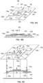
- Figs. 7 and 8 are schematic diagrams showing a configuration of the SoT module 600. Each of arrows in the figure shows the displacement of each piezoelectric element in accordance with the type of arrow (hereinafter the same) .
- the SoT module 600 comprises piezoelectric elements 610a to 610c, elastic bodies 620a and 620b, and a vibration plate 130. Three piezoelectric elements 610a to 610c are connected in an H-shape to form a piezoelectric composite 605.
- the piezoelectric elements 610a and 610b are configured in the same manner as the piezoelectric elements 210a and 210b, respectively.
- the elastic bodies 620a and 620b are formed of the same material and are arranged in the same manner as the elastic bodies 120a and 120b.
- the elastic bodies 620a and 620b support the piezoelectric elements 610a and 610b on the vibration plate 130, respectively, and transmit vibrations of the piezoelectric elements 610a and 610b to the vibration plate 130.
- the piezoelectric element 610c has the same configuration as the piezoelectric element 610a and connects the center portions of the piezoelectric elements 610a and 610b. The connection is made by bonding the back surface of ends of the piezoelectric element 610c and the surface of the center portion of the piezoelectric elements 610a and 610b.
- Fig. 7 is a schematic diagram showing an example of the operation of the SoT module 600. Electrical signals are input to the wiring configured so that the piezoelectric elements 610a to 610c are all driven in phase in the SoT module 600 in which the piezoelectric composite 605 is located on the upper side and the vibration plate 130 is located on the lower side. In the case, displacement occurs as indicated by the arrow shown in Fig. 7 , it is possible to obtain a large displacement of the entire piezoelectric composite 605. In the case that the piezoelectric elements are driven in phase with each other, when the center portions of the piezoelectric elements 610a and 610b are displaced upward, both ends of the piezoelectric element 610c are displaced downward, and the center portion is displaced upward.
- the wiring may be configured so that the piezoelectric elements 610a and 610b can be driven in anti-phases to the piezoelectric element 610c each other, and an electric signal may be input.
- Fig. 8 is a schematic diagram showing an operation example of the SoT module 600. In this case, a displacement occurs as indicated by an arrow in Fig. 8 , and a large displacement can be obtained in the entire piezoelectric composite 605. When the center portions of the piezoelectric elements 610a and 610b are displaced upward, both ends of the piezoelectric element 610c are displaced upward, and the center portion is displaced downward.
- the displacement point can be changed closer to or farther from the elastic bodies 620a and 620b by adjusting the drive signal (anti-phase or in-phase) .
- This adjustment allows amplification of sound pressure at a specific frequency.
- the SoT module may have a structure for amplifying the displacement in a loop.
- four piezoelectric elements are used from the viewpoint of efficiency, but other numbers of piezoelectric elements such as three or five may be used.
- Figs. 9A to 9C are a perspective view, a schematic view, a side view showing an operation of the SoT module 700, respectively.
- the SoT module 700 comprises piezoelectric elements 710a to 710d, elastic bodies 720a to 720d, and a vibration plate 130.
- Each of the piezoelectric elements 710a to 710d has the same element structure as that of the piezoelectric element 110a.
- Four piezoelectric elements 710a to 710d are connected in a loop structure to form a piezoelectric composite 705.
- connection is performed, for example, by bonding the back surface of one end of the piezoelectric element 710a and the front surface of the center portion of the piezoelectric element 710b.
- a region surrounded by a dotted line in Fig. 9A is a bonding region.
- Such connections are performed between the piezoelectric elements 710b and 710c, the piezoelectric elements 710c and 710d, and the piezoelectric elements 710d and 710a, thereby forming the loop structure.
- the vibration of the piezoelectric element can be amplified in a loop through the connected members until saturated, the sound pressure can be improved in the low audio frequency range.
- the positions at which the ends of each of the plurality of piezoelectric elements 710a to 710d are connected are the centers of the other piezoelectric elements.
- the characteristics of the low audio frequency range can be improved.
- the elastic bodies 720a to 720d are made of the same material as that of the elastic body 120a. As described above, one end of the piezoelectric element 710a is connected to the center portion of the other piezoelectric element 710b, and the other end is supported by the elastic body 720a. In this manner, the elastic bodies 720a to 720d support the ends of the piezoelectric elements 710a to 710d on the vibration plate 130, respectively and transmit the vibrations of the piezoelectric elements 710a to 710d to the vibration plate 130.
- the piezoelectric elements 710a to 710d are driven in in-phase or anti-phase, and the driving method thereof is set according to the stiffness of the entire path through which the vibrations are transmitted.
- the sound pressure can be amplified at a specific frequency by adjusting the drive signal (anti-phase or in-phase) to change the displacement point closer to or farther away from the elastic bodies 720a to 720d.
- the connecting destination of one end of the piezoelectric element is a central portion of the other piezoelectric element, but an intermediate portion between the central portion and the end portion may be the destination.
- Fig. 10A is a perspective view of the SoT module 800. The connection is performed by bonding one's back surface to the other's surface. A region surrounded by a dotted line in Fig. 10A is a bonding region.
- the SoT module 800 is configured in the same manner as the SoT module 700 except for the connecting places of the piezoelectric elements 810a to 810d.
- the piezoelectric elements 810a to 810d are driven in in-phase or anti-phase, and the driving method thereof is set according to the stiffness of the entire path through which the vibrations are transmitted. Thus, the characteristics of the middle audio frequency range can be improved.
- the sound pressure can be amplified at a specific frequency by adjusting the drive signal (anti-phase or in-phase) to change the displacement point closer to or farther away from the elastic bodies 820a to 820d.
- the connecting destination of one end of the piezoelectric element is a central portion of the other piezoelectric element, an end portion may be the destination.
- Fig. 10B is a perspective view of the SoT module 900. The connection is performed by bonding one's back surface to the other's surface. A region surrounded by a dotted line in Fig. 10B is a bonding region.
- the SoT module 900 is configured in the same manner as the SoT module 700 except for the connecting places of the piezoelectric elements 910a to 910d.
- the piezoelectric elements 910a to 910d are driven in in-phase or anti-phase, and the driving method thereof is set according to the stiffness of the entire path through which the vibrations are transmitted.
- the sound pressure to be amplified at a specific frequency by adjusting the drive signal (anti-phase or in-phase) to change the displacement point closer to or farther away from the elastic bodies 920a to 920d.
- the piezoelectric elements may be connected so as to cross each other in the longitudinal direction to configure a piezoelectric composite.
- the piezoelectric elements are arranged to intersect each other in the longitudinal direction and overlap the central portions. Then, the back surface of the central portion of the one piezoelectric element is bonded to the surface of the central portion of the other piezoelectric element.
- the displacement of the vibration plate can be amplified, and especially, the sound pressure in the middle audio frequency range from the low audio frequency range can be improved. It is preferable that the crossing is made at an orthogonal angle or an angle at which an effect equivalent thereto can be obtained.
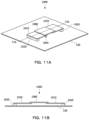
- Figs. 11A and 11B are a perspective view and a cross-sectional view showing the SoT module 1000, respectively.
- the cross-sectional view of Fig. 11B represents a cross-sectional view 11b shown in Fig. 11A .
- the SoT module 1000 is configured of piezoelectric elements 1010, 1080, an elastic body 1020 and a vibration plate 130.
- Each of the piezoelectric elements 1010 and 1080 is a stretching-type piezoelectric element.
- the piezoelectric elements 1010 and 1080 are preferably formed by electrodes and piezoelectric bodies which are formed of piezoelectric ceramics polarized being stacked.
- the piezoelectric elements 1010 and 1080 generate stretching vibration by the impression of an AC voltage.
- the piezoelectric elements 1010 and 1080 are alternately arranged in a single row along the longitudinal direction, by their end portions being connected to each other, to form steps of up and down. Specifically, the back surface of the piezoelectric element 1080 is bonded to the surface of the piezoelectric element 1010 at each of the ends. The piezoelectric elements 1010 are located in a state where a portion overlaps with the piezoelectric element 1080 each other on both sides of the piezoelectric element 1080 located in the center. The piezoelectric elements 1010 and 1080 configure the symmetrical piezoelectric composite 1005.
- the plurality of piezoelectric elements 1010 and 1080 may be driven by an input of a single signal (in-phase drive) or may be driven by different signals by shifting the phase for a central piezoelectric element 1080 relative to the phase of the piezoelectric elements 1010 on both sides.
- the displacement of the piezoelectric composite 1005 with respect to the position is represented by a curve and the curve is overlapped with the one in anti-phase, there is a position where the curves intersect.
- the sound pressure can be amplified at a specific frequency by adjusting the drive signal (anti-phase or in-phase) to change the displacement point closer to or farther away from the elastic bodies 1020. In this manner, the amount of displacement can be amplified through the connecting portion.
- the drive signal anti-phase or in-phase
- Fig. 12A is a perspective view of the SoT module 1100.
- the SoT module 1100 comprises piezoelectric composites 1105a and 1105b, elastic bodies 1120a and 1120b, and a vibration plate 130.
- the piezoelectric composite 1105a is configured in the same manner as the piezoelectric composite 1005, has piezoelectric elements 1110a and 1180a and is formed by connecting respective ends thereof in a row.
- the piezoelectric composite 1105b is also formed by connecting ends of the piezoelectric elements 1110b and 1180b and is configured in the same manner as the piezoelectric composite 1005.
- Fig. 12B is a perspective view of the SoT module 1200.
- the SoT module 1200 comprises a piezoelectric composite 1205, elastic bodies 1220a to 1220d, and a vibration plate 130.
- the piezoelectric composite 1205 comprises a central piezoelectric element 1280 and peripheral piezoelectric elements 1210a to 1210d connected at their ends to the edges of the central piezoelectric element 1280.
- the central piezoelectric element 1280 is larger than each of the peripheral piezoelectric elements 1210a to 1210d.
- the connection direction of the piezoelectric elements 1210a, 1280, and 1210c connected in one row intersects the connection direction of the piezoelectric elements 1210b, 1280, and 1210d connected in another row at perpendicular angle at the center.
- the plurality of piezoelectric elements 1280 and 1210a to 1210d may be driven with a single signal input (in-phase drive) or may be driven with different signals in which the phase for the center piezoelectric element 1280 is out of the phase for the peripheral piezoelectric elements 1210a to 1210d.
- the piezoelectric element 1280 is driven in a shifted phase, it is preferably driven in anti-phase with the peripheral piezoelectric elements 1210a to 1210d.
- the sound pressure can be amplified at a specific frequency by adjusting the drive signal (anti-phase or in-phase) to change the displacement point closer to or farther away from the elastic bodies 1220a to 1220d.
- Each of the connecting portion is shifted to one side from the plane passing through the center of the central piezoelectric element 2280.
- the connecting position of the piezoelectric element 2210d with respect to the plane P1 is shifted toward the piezoelectric element 2210a, and the connecting position of the piezoelectric element 2210b is shifted toward the piezoelectric element 2210c.
- the SoT module 2200 is formed in a windmill-like shape.
- the plane P1 is a bisecting plane that evenly divides the piezoelectric composite 2205, and the piezoelectric composite 2205 is formed such that the shapes of both sides divided by the plane P1 are point symmetric with respect to one point on the plane P1. That is, the piezoelectric composite 2205 has a shape which looks inverted vertically and horizontally when viewed from one side to the other side divided by the plane P1.
- the piezoelectric composite 2205 has the same symmetry not only with respect to the plane P1 but also with respect to a bisecting plane (e.g., the plane P2) that divides evenly regardless of the angle.
- the plurality of piezoelectric elements 2280 and 2210a to 2210d may be driven with a single signal input (in-phase drive) or may be driven with different signals in which the phase for the center piezoelectric element 2280 is out of the phase for the peripheral piezoelectric elements 2210a to 2210d.
- the piezoelectric elements 2210a to 2210d may be driven on peripheral region in anti-phase.
- Figs. 14A and 14B are a perspective view and a cross-sectional view showing the SoT module 1300, respectively.
- the cross-sectional view of Fig. 14B represents the cross-sectional view 13b shown in Fig. 14A .
- the SoT module 1300 comprises a piezoelectric element 1310 and 1390, elastic bodies 1320, a base plate 1360 and a vibration plate 130.
- Each of the piezoelectric elements 1310 and 1390 is a stretching-type piezoelectric element.
- the piezoelectric elements 1310 and 1390 are preferably formed by electrodes and piezoelectric bodies which are formed of piezoelectric ceramics polarized being stacked.
- the piezoelectric elements 1310 and 1390 generate stretching vibration by the impression of an AC voltage.
- the piezoelectric elements 1310 and 1390 are provided in a row along the longitudinal direction on a rectangular base plate 1360.
- the piezoelectric elements 1310 and 1390 are alternately arranged at uniform intervals, and the piezoelectric composite 1305 is symmetrically formed.
- the piezoelectric elements 1310 and 1390 configure a symmetrical piezoelectric composite 1305.
- the plurality of piezoelectric elements 1310 and 1390 may be driven by an input of a single signal (in-phase drive) or may be driven by different signals by shifting the phase for a central piezoelectric element 1390 relative to the phase of the piezoelectric elements 1310 on both sides.
- the displacement of the piezoelectric composite 1305 with respect to the position is represented by a curve and the curve is overlapped with the one in anti-phase, there is a position where the curves intersect.
- the sound pressure can be amplified at a specific frequency by adjusting the drive signal (anti-phase or in-phase) to change the displacement point closer to or farther away from the elastic bodies 1320. In this manner, the amount of displacement can be amplified through the connecting portion. The same effect can be obtained even when the elastic bodies 1320 and the vibration plate 130 are omitted and the base plate 1360 is used as the vibration plate.
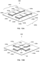
- Fig. 15A is a perspective view of the SoT module 1400.
- the SoT module 1400 comprises piezoelectric composites 1405a and 1405b, elastic bodies 1420a and 1420b, and a vibration plate 130.
- the piezoelectric composite 1405a comprises piezoelectric elements 1410a and 1490a and a base plate 1460a and is configured in the same manner as the piezoelectric composite 1305.
- the piezoelectric composite 1405b also comprises piezoelectric elements 1410b and 1490b and a base plate 1460b and is configured in the same manner as the piezoelectric composite 1305.
- the sound pressure can be amplified at a specific frequency by adjusting the drive signal (anti-phase or in-phase) to change the displacement point closer to or farther away from the elastic bodies 1320. Further, since the piezoelectric composites 1405a and 1405b are arranged in parallel, the amount of displacement can be amplified.
- the driving of the piezoelectric composites 1405a and 1405b can be performed in the same manner as the driving of the piezoelectric composite 1305.
- Fig. 15B is a perspective view of the SoT module 1500.
- the SoT module 1500 comprises a piezoelectric composite 1505, elastic bodies 1520a to 1520d and a vibration plate 130.
- the piezoelectric composite 1505 comprises piezoelectric elements 1510a to 1510d and 1590 and a base plate 1560.
- the piezoelectric elements 1510a to 1510d and 1590 are bonded onto a base plate 1560.
- a central piezoelectric element 1590 and peripheral piezoelectric elements 1510a to 1510d are located on a cross-shaped base plate 1560.
- the peripheral piezoelectric elements 1510a to 1510d are all formed in the same size.
- the size of the central piezoelectric element 1590 is the same as the size of each of the peripheral piezoelectric elements 1510a to 1510d but may be different.
- the plurality of piezoelectric elements 1510a to 1510d and 1590 may be driven by an input of a single signal (in-phase drive) or may be driven by different signals by shifting the phase for a central piezoelectric element 1590 relative to the phase of the peripheral piezoelectric elements 1510a to 1510d.
- a single signal in-phase drive
- different signals by shifting the phase for a central piezoelectric element 1590 relative to the phase of the peripheral piezoelectric elements 1510a to 1510d.
- the sound pressure can be amplified at a specific frequency by adjusting the drive signal (anti-phase or in-phase) to change the displacement point closer to or farther away from the elastic bodies 1520a to 1520d.
- the SoT module may be configured of a structure having a high thermal conductivity.
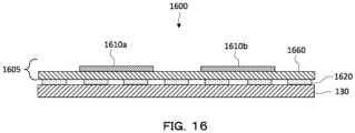
- Fig. 16 is a cross-sectional view showing the SoT module 1600.
- the SoT module 1600 comprises piezoelectric elements 1610a and 1610b, a base plate 1660, elastic bodies 1620, and a vibration plate 130.
- the base plate 1660 is preferably formed of metal.
- Each of the piezoelectric elements 1610a and 1610b has an element structure similar to that of the piezoelectric element 110a.
- the elastic bodies 1620 supports the base plate 1660 on the vibration plate 130 in the same material and arrangement as the elastic bodies 420 and transmits the vibration of the piezoelectric composite 1605 to the vibration plate 130. Since one end of the elastic body 1620 is bonded to the base plate 1660, heat accumulated in the piezoelectric elements 1610a and 1610b can be discharged.
- the elastic body 1620 is preferably formed of an elastomer. Further, the elastic body preferably has a thermal coefficient of 1 ⁇ 10 -4 cal ⁇ s -1 cm -2 or more. Thus, the elastic body 1620 can discharge heat with high thermal conductivity.
- the SoT module of the sixteenth embodiment is configured of piezoelectric elements, a base plate, elastic bodies and a vibration plate, but it may further have a partition.
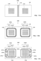
- Fig. 17A is a cross-sectional view showing the SoT module 1700.
- Fig. 17A shows a cross-section of the elastic bodies 1720 cut in a plane parallel to the vibration plate 130.
- the SoT module 1700 comprises a piezoelectric element, an elastic body 1720, a vibration plate 130 and a partition 1770.
- the piezoelectric element has the same element structure as the piezoelectric element 110.
- the piezoelectric elements are preferably connected to each other.
- the plurality of piezoelectric elements are separated to the left and right to form the piezoelectric composites.
- the elastic body 1720 has one end bonded to the piezoelectric composite and the other end bonded to the vibration plate 130, and an assembly of the elastic bodies 1720 is formed for each of the two piezoelectric composites. Between them, the partition 1770 is provided. By the partition 1770, the acoustic interference in the left and right speakers can be suppressed.
- the partition may have a structure surrounding the assembly of the elastic bodies.
- Fig. 17B is a cross-sectional view showing the SoT module 1800.
- Fig. 17B shows a cross section when the elastic bodies 1720 are cut in a plane parallel to the vibration plate 130.
- the SoT module 1800 is configured in the same manner as the SoT module 1700 except that partitions 1870a and 1870b are provided instead of the partition 1770.
- the partitions 1870a and 1870b surround assemblies of left and right elastic bodies 1720, respectively.
- the partitions 1870a and 1870b are configured of inner partitions 1871a and 1871b and outer partitions 1872a and 1872b, respectively. Since the partitions 1870a and 1870b have double structures surrounding the elastic bodies 1720, the sound is hardly transmitted to the outside of each of the partitions. Thus, it is possible to effectively suppress the acoustic interference occurring inside the left and right respective speakers.
- Fig. 17C is a plan view showing the SoT module 1900.
- Fig. 17C shows a cross section when the elastic bodies 1720 are cut in a plane parallel to the vibration plate 130.
- the SoT module 1900 is configured in the same manner as the SoT module 1800 except that the partitions 1870a and 1870b are replaced with partitions 1970a and 1970b.
- the partitions 1970a and 1970b are provided so as to surround respective assemblies of the left and right elastic bodies 1720.
- the partitions 1970a and 1970b are configured of inner partitions 1971a and 1971b and outer partitions 1972a and 1972b, respectively.
- the partitions 1970a and 1970b have double structures surrounding the elastic bodies 1720.
- the SoT module configured as described above can be used in various applications.
- the applications can be roughly classified into acoustic and noise cancellation.
- Noise cancellation is a technique that uses sounds with anti-phases and is particularly effective for removing regular noise such as motor sounds. Though it is said to be difficult to cancel the noise of 1kHz or less, the SoT module can also sufficiently work for the noise cancellation of 1kHz or less.
- the SoT module can be configured by installing the piezoelectric elements and the elastic bodies there.
- parts of plastic panels of automobile doors, ceilings, trunks, headrests, and dashboards can be utilized as vibration plates to configure the SoT modules.
- sounds generated by placing the SoT module at various positions are audible to the listener as spatially balanced sounds rather than sounds spreading from one position.
- sound can be generated at a small volume from the back portion of the front seat or behind the seat.
- the SoT module can be used for a noise canceller in an automobile.
- the SoT module is formed under the sheet, and the noise can be canceled with the sound in anti-phase to the engine sound.
- the SoT module can be used for noise cancellation of a washing machine.
- the SoT module can be installed in the washing machine itself or can be installed in attachments of the washing machine.
- the sound leaked from the washing machine is a low sound of 1kHz or less passing through the soundproofing material, and this sound can not be cancelled by the usual piezoelectric module, but it can be cancelled by the SoT module.
- CSO Cinematic Sound OLDE
- Typical applications of the SoT module comprise Cinematic Sound OLDE (CSO).
- CSO is a technique in which acoustic techniques are added to the self-emitting OLED to match the sound positions of the screens with the actual sound generating positions .
- OLED panel as a vibration plate
- the user can hear sound according to the image by directly transmitting sound from OLED screen, rather than from a separate speaker installed in the TV. That is, the user can hear the sound of talking with each other from the mouth of the performers of movies and dramas and can also hear the sound of the rain falling from the sky touching the ground from the position where the rain hits the ground on the actual screen. In this way, the user gets more immersion feeling.
- This application is not limited to TV, and the SoT module can be similarly applied to signage.
- the SoT module is also applicable to furniture and architectural components.
- the piezoelectric elements and the elastic bodies can be installed in the box-shaped drawer used in the rack frame are assembled to form a SoT module.
- the inside of the desk drawer can be sounded, and the inside of the box can be used as a speaker. Even if the drawer is filled with objects, a desired sound can be generated.
- Piezoelectric elements and elastic bodies can also be installed on the iron plates behind LED projectors installed on roads, and iron plates can be used with vibration plates to configure SoT modules.
- An audible alarm can be generated directly from the LED projector, for example.
- Such a configuration is also possible with a speaker by a coil in terms of sound pressure in the low audio frequency range, it is impossible to secure the space in the building. Further, a loudspeaker with a coil requires a strong power source, which may be subject to legal restrictions. SoT modules can be installed in small spaces, and they can be retrofitted by domestic power source for general use.
- Formula (1) is a mathematical expression representing a natural frequency fs of a piezoelectric module.
- M and S represent the mass and stiffness of the piezoelectric module, respectively.
- the overall stiffness value mainly depends on the stiffness of the elastic body.
- the stiffness of the elastic body can be reduced. Further, since the stiffness of the entire system is also dependent on the tensile strength of the vibration plate, it is also possible to improve the sound pressure of low audio frequency sound according to the selection of the material of the vibration plate.
- the transmissibility is lowered by the weight of the vibration plate, and there is also a possibility that the sound pressure characteristics deteriorate.
- the bonding strength between the piezoelectric composite and the vibration plate is increased to increase the transfer coefficient, the piezoelectric composite must receive all the weight of the panel, and the amplitude cannot be maintained.
- sound pressure can be improved not only by adding an elastic body to the vibration path but also by adjusting the damping ratio of the vibration transmission path.
- Piezoelectric modules for testing were prepared by varying the arrangement of elastic bodies, and the frequency characteristics of sound pressure were measured.
- Fig. 18A is a side view showing the piezoelectric modules t1 to t3 for testing in which the positions of the elastic bodies differ from each other.
- the piezoelectric module t1 for testing is configured of the piezoelectric element v1, the elastic body u1, and the vibration plate w1.
- the piezoelectric element v1 is a bending-type piezoelectric element using PZT.
- the elastic body u1 has a length of 8mm in the longitudinal direction of the piezoelectric element v1 and is formed of urethane, one surface is bonded to the central portion in the longitudinal direction of the piezoelectric element v1.
- the vibration plate w1 is a OLED panel and is bonded to the other surface of the elastic body u1.
- the piezoelectric module t2 for testing is configured of the piezoelectric element v1, the elastic bodies u2, the vibration plate w2.
- the two elastic bodies u2 respectively have the length of 8mm in the longitudinal direction of the piezoelectric element v1 and is formed of urethane in the same manner as the elastic body u1, but they are respectively located at intermediate positions between the central portion and both end portions in the longitudinal direction of the element v1.
- the piezoelectric module t3 for testing is configured of the piezoelectric element v1, the elastic bodies u3, the vibration plate w1.
- the two elastic bodies u3 respectively have the length of 8mm in the longitudinal direction of the piezoelectric element v1 and is formed of urethane in the same manner as the elastic body u1, but they are respectively located at both ends in the longitudinal direction of the piezoelectric element v1.
- Fig. 18B is a graph showing the frequency characteristics of the sound pressure of the piezoelectric modules t1 to t3 for testing. As shown in Fig. 18B , the peak dip in the middle audio frequency region occurring with the piezoelectric modules t1 and t2 for testing does not occur with the piezoelectric module t1 for testing.
- Fig. 19A is a side view showing the piezoelectric modules t4 and t5 for testing in which the shapes of the elastic bodies differ.
- the SoT module 1300 of the thirteenth embodiment (example E13 (single base plate type)) was prepared, the central piezoelectric element 1390 was driven in in-phase drive or anti-phase to the piezoelectric elements 1310 on both sides of the center, and frequency characteristics of the sound pressure were measured.
- Fig. 24 is a graph showing the frequency characteristics of the sound pressure of the SoT module when driven in-phase and anti-phase for the example E13. As shown in Fig. 24 , the sound pressure in the low audio frequency range is improved in the anti-phase drive, and the sound pressure in the middle and high audio frequency range is improved in the in-phase drive.
Landscapes
- Engineering & Computer Science (AREA)
- Physics & Mathematics (AREA)
- Acoustics & Sound (AREA)
- Signal Processing (AREA)
- Multimedia (AREA)
- Piezo-Electric Transducers For Audible Bands (AREA)
Description
- The present invention relates to a piezoelectric module comprising a piezoelectric element formed in a rectangular plate.
- In the acoustic field, a dynamic speaker configured by a coil is generally used. Although a dynamic speaker can generate sufficient sound pressure even in the low audio frequency range, the application is limited since the weight, the volume and the power consumption of the dynamic speaker are large. On the other hand, the application of the piezoelectric speaker using the piezoelectric element has been advanced (e.g., see Patent Document 1) . Since the volume, the weight and the power consumption of a piezoelectric speaker are small, the piezoelectric speaker can also be used in applications difficult to apply dynamic speakers.
- Patent Document 2 describes a piezoelectric oscillation unit including a rectangular first conductor plate; a support portion for supporting the opposite ends of the first conductor plate in the longitudinal direction; a planar piezoelectric element fixed to at least one principal surface of the first conductor plate; a first coupling portion formed on at least a part of one side face of the first conductor plate parallel with the longitudinal direction; a second coupling portion formed on at least a part of the other side face of the first conductor plate parallel with the longitudinal direction; a first weight connecting with the first coupling portion; and a second weight connecting with the second coupling portion.
Further, Patent Document 3 describes a small-size thin piezoelectric actuator mountable on a mobile electronic device to give a contact feeling of a three dimensional movement to a user's hand palm. The piezoelectric actuator comprises a piezoelectric ceramic oscillator having a piezoelectric ceramic thin plate bonded to at least one surface of a shim member, at least one holder for holding the shim member, and a sheet-shaped elastic body. -
- [Patent Document 1]
Japanese Patent No. 3798678 - [Patent Document 2]
JP 2015 149632 A - [Patent Document 3]
US 2010/165794 A1 - However, in the piezoelectric speaker, it is difficult to obtain a sufficient sound pressure in the low and middle audio frequency range. As a result, the sound pressure as a whole is often reduced. If the demerit is overcome, the piezoelectric module can be applied not only to speakers for watching television programs, movies, music, and the like, but also to various applications. A piezoelectric module that can obtain sufficient sound pressure in the low and middle audio frequency range is available for a loudspeaker and noise canceller, even if it does not have an acoustic structure such as a hole and cavity, as long as it has a vibration plate .
- Such a piezoelectric module has the potential to be quite different from a conventional piezoelectric module and should be referred to as a SoT (Sound of Things) module (hereinafter, piezoelectric modules that can improve sound pressure in a particular audio frequency range are referred to as a SoT module).
- From the above circumstances, the inventors of the present invention have continued trial and error in the development of a piezoelectric module by which sufficient sound pressure is obtained even in the low and middle audio frequency range. For example, in the
piezoelectric module 2100 shown inFig. 25 , on thevibration plate 2130, thepiezoelectric element 2110 is provided with a central portion supported by theelastic body 2120. As the material of theelastic body 2120 and thevibration plate 2130 of suchpiezoelectric module 2100, various materials have been tried. - Also, an attempt to increase the sound pressure by providing a plurality of piezoelectric elements has been made. In the piezoelectric module 3100 shown in
Fig. 26 , the sound pressure is increased by providing two piezoelectric elements 3110a and 3110b in parallel supported at the centers by elastic bodies 3120a and 3120b. However, even in such improved piezoelectric module 3100, sufficient sound pressure has not been obtained in the low and middle audio frequency range. - The present invention has been made in view of such circumstances, a SoT module that generates sufficient sound pressure in the low and middle audio frequency range and can be applied to a variety of applications is provided.
- To achieve the above object, a piezoelectric module according to
claim 1 comprises a plate-shaped piezoelectric composite for generating bending vibration by the impression of an AC voltage, a plurality of elastic bodies, one ends of which are bonded to a main surface of the piezoelectric composite, the elastic bodies transmitting vibration of the piezoelectric composite, and a vibration plate having a main surface which is bonded to other ends of the elastic bodies, wherein the piezoelectric composite comprises a piezoelectric element formed in a rectangular plate, there is a position of a centroid of the piezoelectric composite between the plurality of elastic bodies, and the piezoelectric composite comprises a plurality of piezoelectric elements, each of which is identical to the piezoelectric element, and each of the piezoelectric elements is partially connected to each other. - The above object is alternatively also achieved by providing a piezoelectric module according to claim 9.
- Thus, the stiffness of the entire module can be reduced, and the displacement amplitude of the vibration plate can be increased. As a result, sufficient sound pressure is obtained in the low and middle audio frequency range, and it can be applied to various applications.
-
-
Fig. 1 is a perspective view showing a SoT module according to the first embodiment. -
Fig. 2 is a cross-sectional view showing an example of a configuration and operation of the piezoelectric element. -
Fig. 3 is a perspective view showing a SoT module according to the second embodiment. -
Figs. 4A and 4B are a plan view and a cross-sectional view showing a SoT module according to the third embodiment, respectively. -
Figs. 5A and 5B are a plan view and a cross-sectional view showing a SoT module according to the fourth embodiment, respectively. -
Figs. 6A and 6B are a plan view and a cross-sectional view showing a SoT module according to a fifth embodiment, respectively. -
Fig. 7 is a schematic diagram showing an example of a configuration and an operation (in-phase) of a SoT module according to the sixth embodiment. -
Fig. 8 is a schematic diagram showing an example of a configuration and an operation of a SoT module according to the sixth embodiment. -
Figs. 9A to 9C are a perspective view, a schematic view, a side view showing an operation of a SoT module according to the seventh embodiment, respectively. -
Figs. 10A and 10B are perspective views of a SoT modules according to eighth and ninth embodiments, respectively. -
Figs. 11A and 11B are a perspective view and a cross-sectional view showing a SoT module according to the tenth embodiment, respectively. -
Figs. 12A and 12B are perspective views showing SoT modules according to the eleventh embodiment and the twelfth embodiment, respectively. -
Figs. 13A and 13B are a plan view and a cross-sectional view showing a SoT module of the twelfth embodiment, respectively. -
Figs. 14A and 14B are a perspective view and a cross-sectional view showing SoT modules according to the thirteenth embodiment, respectively. -
Figs. 15A and 15B are perspective views showing the SoT modules according to fourteenth and fifteenth embodiments, respectively. -
Fig. 16 is a cross-sectional view showing a SoT module according to the sixteenth embodiment. -
Figs. 17A and 17C are plan views showing SoT modules according to the seventeenth to nineteenth embodiments, respectively. -
Figs. 18A and 18B are a side view showing piezoelectric modules for testing in which the positions of the elastic bodies differ from each other and a graph showing the frequency characteristics of their sound pressure, respectively. -
Figs. 19A and 19B are a side view showing piezoelectric modules for testing in which the shapes of the elastic bodies differ and a graph showing the frequency characteristics of their sound pressure, respectively. -
Fig. 20 is a graph showing the frequency characteristics of the sound pressure of the SoT modules for the respective embodiment. -
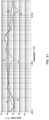
Fig. 21 is a graph showing the frequency characteristics of the sound pressure of the SoT modules for the respective embodiment. -
Fig. 22 is a graph showing the frequency characteristics of the sound pressure of the SoT modules for the respective embodiment. -
Fig. 23 is a graph showing the frequency characteristics of the sound pressure of the SoT modules for the respective embodiment. -
Fig. 24 is a graph showing the frequency characteristics of the sound pressure of a SoT module which is driven in-phase and anti-phase for the example E13. -
Fig. 25 is a perspective view showing a conventional piezoelectric module. -
Fig. 26 is a perspective view showing a conventional piezoelectric module. - Next, embodiments of the present invention are described with reference to the drawings.
-
Fig. 1 is a perspective view showing aSoT module 100. TheSoT module 100 comprisespiezoelectric elements elastic bodies vibration plate 130. Each of thepiezoelectric elements - The
piezoelectric elements elastic bodies piezoelectric elements SoT module 100 can be applied to a variety of applications. Each of thepiezoelectric elements -
Fig. 2 is a cross-sectional view showing an example of the configuration and operation of thepiezoelectric element 110. Thepiezoelectric element 110 is an example of the configuration of thepiezoelectric elements piezoelectric element 110 comprisespiezoelectric bodies electrodes shim plate 115. Theshim plate 115 is made of metal and also has the function of an electrode. - The
piezoelectric bodies piezoelectric bodies -
Piezoelectric body 111 is polarized in the direction of theshim plate 115 from theelectrode 113, thepiezoelectric body 112 is polarized in the direction of theelectrode 114 from theshim plate 115. One electrode is connected to theelectrodes shim plate 115. In this configuration, when an AC voltage is impressed to thepiezoelectric bodies Fig. 2 . - The above-described
piezoelectric element 110 has a parallel bimorph structure in which the polarization directions of thepiezoelectric bodies piezoelectric element 110 preferably has a bimorph structure but may have a unimorph structure. Further, for thepiezoelectric element 110, a piezoelectric multilayer body may be used in place of the piezoelectric body of a single plate. In this case, an external electrode may be used, or an electrode may be formed by a via structure. Further, thepiezoelectric element 110 is formed by the piezoelectric layer and the electrode being stacked, it may be a stretching-type piezoelectric element which expands and contracts in the stacking direction. - The
elastic body 120a has one end bonded to the main surface of thepiezoelectric element 110a and the other end bonded to the main surface of thevibration plate 130, and the elastic body120b has one end bonded to the main surface of thepiezoelectric element 110b and the other end bonded to the main surface of thevibration plate 130. For example, an epoxy-based, acrylic-based, or urethane-based adhesive can be used for bonding (hereinafter, for any bonding is the same) . Theelastic bodies elastic bodies elastic bodies piezoelectric elements vibration plate 130. - Between the
elastic bodies piezoelectric elements entire SoT module 100 can be reduced, and the peak dip in the middle audio frequency range occurred for thepiezoelectric elements elastic bodies piezoelectric elements piezoelectric elements - Each of the
elastic bodies Fig. 1 but may be formed in a cylindrical shape or an elliptical cylindrical shape. Theelastic bodies piezoelectric elements - The
vibration plate 130 is formed in a plate shape and bonded to theelastic bodies vibration plate 130 varies depending on the application. For example, a styrene board can be used as thevibration plate 130. Further, it is possible to use a OLED panel as thevibration plate 130 of the TV speaker. Although thevibration plate 130 made of resin is easily used, a vibration plate with inelasticity enhanced using wood or fiber structure may be used. - The
vibration plate 130 vibrates in the thickness direction by the displacement force transmitted through theelastic bodies piezoelectric elements vibration plate 130 appear differently for magnitude. In order to generate a large sound pressure, it is effective to improve the efficiency of vibration which is connected to the vibration plate. - The operation of the
SoT module 100 is described below. By the electrical signal for the sound amplified by the amplifier being input to theSoT module 100, the piezoelectric composite 105 vibrates. Then, the displacement due to the vibration is transmitted to thevibration plate 130 via theelastic bodies vibration plate 130 vibrates to generate a sound corresponding to the electric signal. - The unconnected
piezoelectric elements piezoelectric elements vibration plate 130 is large, when the stiffness of theelastic bodies - Although the independent two piezoelectric elements are arranged in parallel in the above embodiment, the piezoelectric elements installed in parallel may be connected by connecting members.
Fig. 3 is a perspective view showing theSoT module 200. - The
SoT module 200 comprisespiezoelectric elements elastic bodies members vibration plate 130. Thepiezoelectric elements piezoelectric elements piezoelectric elements vibration plate 130, and a part of each other is connected to configure a plate-shapedpiezoelectric composite 205. Thus, the vibration is amplified through the connecting portion, the displacement amplitude of thevibration plate 130 can be increased. Each of theelastic bodies elastic bodies - Each of the two connecting
members piezoelectric element 210a and the end of thepiezoelectric element 210b. The connecting is performed by bonding the back surfaces of the connectingmembers piezoelectric elements members members piezoelectric elements members piezoelectric composite 205. In the cross-sectional view, the electrodes of thepiezoelectric elements - It is preferable that the
piezoelectric elements piezoelectric elements piezoelectric elements members - For example, the
piezoelectric elements piezoelectric elements SoT module 200 in which thepiezoelectric composite 205 is located on the upper side and thevibration plate 130 is located on the lower side. In this case, when the central portion of thepiezoelectric element 210a is displaced downward, the central portion of thepiezoelectric element 210b is displaced upward. - The
piezoelectric elements piezoelectric element 210a is displaced downward, the center portion of thepiezoelectric element 210b is also displaced downward. When the central portion of thepiezoelectric element 210a is displaced upward, the central portion of thepiezoelectric element 210b is also displaced upward. - The
SoT module 200 is preferably driven by a drive method for increasing the sound pressure of the low audio frequency range. When the displacement of the piezoelectric composite 205 with respect to the position is represented by a curve and the curve is overlapped with the one in anti-phase, there is a position where the curves intersect. This position would be called a displacement point, and the displacement point can be changed closer to or farther from theelastic bodies - In the second embodiment, although the rectangular plate-shaped elastic body is provided only at the positions of both end portions of the piezoelectric element, the elastic body may be provided over the entire vibration plate. The elastic body may have a uniform plate shape or may be formed in a predetermined pattern as described later.
-
Figs. 4A and 4B are plan and cross-sectional views showing theSoT module 300, respectively. The cross-sectional view of theFig. 4B represents thecross-section 4b shown inFig. 4A . TheSoT module 300 is configured in the same manner as theSoT module 200 except for theelastic body 320. - On the other hand, the
elastic body 320 is formed in a uniform plate shape over theentire vibration plate 130. Thus, since theelastic body 320 is easily arranged, the stiffness of theSoT module 300 can be reduced by theelastic body 320 while the manufacturing load is reduced. The operation of theSoT module 300 is the same as that of theSoT module 200. -
Figs. 5A and 5B are plan and cross-sectional views showing theSoT module 400, respectively. The cross-sectional view ofFig. 5B represents thecross-section 5b shown inFig. 5A . TheSoT module 400 is configured in the same manner as theSoT module 300 except for theelastic body 420. - The
elastic body 420 has a constant pattern shape over a cross section perpendicular to the thickness direction over theentire vibration plate 130. The constant pattern shape is preferably a shape in which a plurality of cylindrical holes are arranged periodically. Further, it is more preferable that a plurality of types of cylindrical holes having different diameters are provided. Thus, the constraint to thepiezoelectric composite 205 becomes loose, and the displacement is not hindered. As a result, the stiffness S value of the whole system can be lowered, and the damping ratio of the vibration transmission path can be optimized. -
Figs. 6A and 6B are a plan view and a cross-sectional view showing theSoT module 500 according to a fifth embodiment, respectively. The cross-sectional view ofFig. 6B represents thecross-section 6b shown inFig. 6A . TheSoT module 500 is configured in the same manner as theSoT module 300 except for theelastic body 520. - The
elastic body 420 has a constant pattern shape on a cross section perpendicular to the thickness direction over theentire vibration plate 130. The constant pattern shape is preferably a shape in which a plurality of spherical projections or cylinders are arranged periodically. Thus, the constraint to thepiezoelectric composite 205 becomes loose, and the displacement is not hindered. As a result, the stiffness S value of the whole system can be lowered, and the damping ratio of the vibration transmission path can be optimized. - Although two piezoelectric elements are used in the above embodiment, three piezoelectric elements may be connected for the SoT module. In that case, the central portion of the SoT module installed in parallel can be connected by a piezoelectric element.
-
Figs. 7 and8 are schematic diagrams showing a configuration of theSoT module 600. Each of arrows in the figure shows the displacement of each piezoelectric element in accordance with the type of arrow (hereinafter the same) . TheSoT module 600 comprisespiezoelectric elements 610a to 610c,elastic bodies vibration plate 130. Threepiezoelectric elements 610a to 610c are connected in an H-shape to form apiezoelectric composite 605. - The
piezoelectric elements piezoelectric elements elastic bodies elastic bodies elastic bodies piezoelectric elements vibration plate 130, respectively, and transmit vibrations of thepiezoelectric elements vibration plate 130. - The
piezoelectric element 610c has the same configuration as thepiezoelectric element 610a and connects the center portions of thepiezoelectric elements piezoelectric element 610c and the surface of the center portion of thepiezoelectric elements -
Fig. 7 is a schematic diagram showing an example of the operation of theSoT module 600. Electrical signals are input to the wiring configured so that thepiezoelectric elements 610a to 610c are all driven in phase in theSoT module 600 in which thepiezoelectric composite 605 is located on the upper side and thevibration plate 130 is located on the lower side. In the case, displacement occurs as indicated by the arrow shown inFig. 7 , it is possible to obtain a large displacement of the entirepiezoelectric composite 605. In the case that the piezoelectric elements are driven in phase with each other, when the center portions of thepiezoelectric elements piezoelectric element 610c are displaced downward, and the center portion is displaced upward. - The wiring may be configured so that the
piezoelectric elements piezoelectric element 610c each other, and an electric signal may be input.Fig. 8 is a schematic diagram showing an operation example of theSoT module 600. In this case, a displacement occurs as indicated by an arrow inFig. 8 , and a large displacement can be obtained in the entirepiezoelectric composite 605. When the center portions of thepiezoelectric elements piezoelectric element 610c are displaced upward, and the center portion is displaced downward. - when the curves of the displacements of the piezoelectric composite 605 in anti-phases are overlapped and the position where the curves intersect is called a displacement point, the displacement point can be changed closer to or farther from the
elastic bodies piezoelectric composite 605 and transmitting vibration to thevibration plate 130, it is possible to improve the sound pressure of the low audio frequency range. - In the above embodiments, there is a termination in the amplification path of the displacement of the piezoelectric element, but the SoT module may have a structure for amplifying the displacement in a loop. In the following example, four piezoelectric elements are used from the viewpoint of efficiency, but other numbers of piezoelectric elements such as three or five may be used.
-
Figs. 9A to 9C are a perspective view, a schematic view, a side view showing an operation of theSoT module 700, respectively. TheSoT module 700 comprisespiezoelectric elements 710a to 710d,elastic bodies 720a to 720d, and avibration plate 130. Each of thepiezoelectric elements 710a to 710d has the same element structure as that of thepiezoelectric element 110a. Fourpiezoelectric elements 710a to 710d are connected in a loop structure to form apiezoelectric composite 705. - The connection is performed, for example, by bonding the back surface of one end of the
piezoelectric element 710a and the front surface of the center portion of thepiezoelectric element 710b. A region surrounded by a dotted line inFig. 9A is a bonding region. Such connections are performed between thepiezoelectric elements piezoelectric elements piezoelectric elements piezoelectric elements 710a to 710d are connected are the centers of the other piezoelectric elements. Thus, the characteristics of the low audio frequency range can be improved. - The
elastic bodies 720a to 720d are made of the same material as that of theelastic body 120a. As described above, one end of thepiezoelectric element 710a is connected to the center portion of the otherpiezoelectric element 710b, and the other end is supported by theelastic body 720a. In this manner, theelastic bodies 720a to 720d support the ends of thepiezoelectric elements 710a to 710d on thevibration plate 130, respectively and transmit the vibrations of thepiezoelectric elements 710a to 710d to thevibration plate 130. Thepiezoelectric elements 710a to 710d are driven in in-phase or anti-phase, and the driving method thereof is set according to the stiffness of the entire path through which the vibrations are transmitted. The sound pressure can be amplified at a specific frequency by adjusting the drive signal (anti-phase or in-phase) to change the displacement point closer to or farther away from theelastic bodies 720a to 720d. - In the seventh embodiment, the connecting destination of one end of the piezoelectric element is a central portion of the other piezoelectric element, but an intermediate portion between the central portion and the end portion may be the destination.
Fig. 10A is a perspective view of theSoT module 800. The connection is performed by bonding one's back surface to the other's surface. A region surrounded by a dotted line inFig. 10A is a bonding region. TheSoT module 800 is configured in the same manner as theSoT module 700 except for the connecting places of thepiezoelectric elements 810a to 810d. Thepiezoelectric elements 810a to 810d are driven in in-phase or anti-phase, and the driving method thereof is set according to the stiffness of the entire path through which the vibrations are transmitted. Thus, the characteristics of the middle audio frequency range can be improved. The sound pressure can be amplified at a specific frequency by adjusting the drive signal (anti-phase or in-phase) to change the displacement point closer to or farther away from theelastic bodies 820a to 820d. - In the seventh embodiment, the connecting destination of one end of the piezoelectric element is a central portion of the other piezoelectric element, an end portion may be the destination.
Fig. 10B is a perspective view of theSoT module 900. The connection is performed by bonding one's back surface to the other's surface. A region surrounded by a dotted line inFig. 10B is a bonding region. TheSoT module 900 is configured in the same manner as theSoT module 700 except for the connecting places of thepiezoelectric elements 910a to 910d. Thepiezoelectric elements 910a to 910d are driven in in-phase or anti-phase, and the driving method thereof is set according to the stiffness of the entire path through which the vibrations are transmitted. Thus, the characteristics of the high audio frequency range can be improved. The sound pressure to be amplified at a specific frequency by adjusting the drive signal (anti-phase or in-phase) to change the displacement point closer to or farther away from the elastic bodies 920a to 920d. - The piezoelectric elements may be connected so as to cross each other in the longitudinal direction to configure a piezoelectric composite. For example, the piezoelectric elements are arranged to intersect each other in the longitudinal direction and overlap the central portions. Then, the back surface of the central portion of the one piezoelectric element is bonded to the surface of the central portion of the other piezoelectric element. Thus, the displacement of the vibration plate can be amplified, and especially, the sound pressure in the middle audio frequency range from the low audio frequency range can be improved. It is preferable that the crossing is made at an orthogonal angle or an angle at which an effect equivalent thereto can be obtained.
- In the above embodiment, the bending-type piezoelectric element is used, but a stretching-type piezoelectric element may be used. As the stretching-type piezoelectric element, it is preferable to use a piezoelectric element obtained by stacking a piezoelectric body and an electrode in the expansion direction.
Figs. 11A and 11B are a perspective view and a cross-sectional view showing theSoT module 1000, respectively. The cross-sectional view ofFig. 11B represents across-sectional view 11b shown inFig. 11A . - The
SoT module 1000 is configured ofpiezoelectric elements elastic body 1020 and avibration plate 130. Each of thepiezoelectric elements piezoelectric elements piezoelectric elements - The
piezoelectric elements piezoelectric element 1080 is bonded to the surface of thepiezoelectric element 1010 at each of the ends. Thepiezoelectric elements 1010 are located in a state where a portion overlaps with thepiezoelectric element 1080 each other on both sides of thepiezoelectric element 1080 located in the center. Thepiezoelectric elements symmetrical piezoelectric composite 1005. - The plurality of
piezoelectric elements piezoelectric element 1080 relative to the phase of thepiezoelectric elements 1010 on both sides. The displacement of the piezoelectric composite 1005 with respect to the position is represented by a curve and the curve is overlapped with the one in anti-phase, there is a position where the curves intersect. The sound pressure can be amplified at a specific frequency by adjusting the drive signal (anti-phase or in-phase) to change the displacement point closer to or farther away from theelastic bodies 1020. In this manner, the amount of displacement can be amplified through the connecting portion. When onlypiezoelectric element 1080 is driven in a shifting the phase, it is preferably driven in anti-phase with thepiezoelectric element 1010 on both sides. -
Fig. 12A is a perspective view of theSoT module 1100. TheSoT module 1100 comprisespiezoelectric composites elastic bodies vibration plate 130. The piezoelectric composite 1105a is configured in the same manner as the piezoelectric composite 1005, haspiezoelectric elements piezoelectric elements piezoelectric composite 1005. The sound pressure can be amplified at a specific frequency by adjusting the drive signal (anti-phase or in-phase) to change the displacement point closer to or farther away from theelastic bodies piezoelectric composites piezoelectric composites piezoelectric composite 1005. -
Fig. 12B is a perspective view of theSoT module 1200. TheSoT module 1200 comprises a piezoelectric composite 1205,elastic bodies 1220a to 1220d, and avibration plate 130. The piezoelectric composite 1205 comprises a centralpiezoelectric element 1280 and peripheralpiezoelectric elements 1210a to 1210d connected at their ends to the edges of the centralpiezoelectric element 1280. The centralpiezoelectric element 1280 is larger than each of the peripheralpiezoelectric elements 1210a to 1210d. The connection direction of thepiezoelectric elements piezoelectric elements - The plurality of
piezoelectric elements center piezoelectric element 1280 is out of the phase for the peripheralpiezoelectric elements 1210a to 1210d. When only thepiezoelectric element 1280 is driven in a shifted phase, it is preferably driven in anti-phase with the peripheralpiezoelectric elements 1210a to 1210d. The sound pressure can be amplified at a specific frequency by adjusting the drive signal (anti-phase or in-phase) to change the displacement point closer to or farther away from theelastic bodies 1220a to 1220d. - The central piezoelectric element may be connected to the vibration plate side of the peripheral piezoelectric elements. Further, each of the connecting portions may be shifted to one side from the plane passing through the center of the central piezoelectric element.
Figs. 13A and 13B are plan and cross-sectional views showing theSoT module 2200. The cross-sectional view ofFig. 13B represents across-section 13b shown inFig. 13A . - The
SoT module 2200 comprises a piezoelectric composite 2205,elastic bodies 2220a to 2220d, and avibration plate 130. The piezoelectric composite 2205 comprises a centralpiezoelectric element 2280 and peripheralpiezoelectric elements 2210a-2210d whose ends are connected to the edges of the centralpiezoelectric element 2280. The width of the centralpiezoelectric element 2280 is larger than the width of the peripheralpiezoelectric elements 2210a to 2210d. The centralpiezoelectric element 2280 is connected to thevibration plate 130 side of the peripheralpiezoelectric elements 2210a to 2210d. The connection direction of thepiezoelectric elements piezoelectric elements - Each of the connecting portion is shifted to one side from the plane passing through the center of the central
piezoelectric element 2280. For example, the connecting position of thepiezoelectric element 2210d with respect to the plane P1 is shifted toward thepiezoelectric element 2210a, and the connecting position of thepiezoelectric element 2210b is shifted toward thepiezoelectric element 2210c. In this way, theSoT module 2200 is formed in a windmill-like shape. - The plane P1 is a bisecting plane that evenly divides the piezoelectric composite 2205, and the piezoelectric composite 2205 is formed such that the shapes of both sides divided by the plane P1 are point symmetric with respect to one point on the plane P1. That is, the piezoelectric composite 2205 has a shape which looks inverted vertically and horizontally when viewed from one side to the other side divided by the plane P1. The piezoelectric composite 2205 has the same symmetry not only with respect to the plane P1 but also with respect to a bisecting plane (e.g., the plane P2) that divides evenly regardless of the angle.
- The plurality of
piezoelectric elements center piezoelectric element 2280 is out of the phase for the peripheralpiezoelectric elements 2210a to 2210d. When onlypiezoelectric element 2280 is driven by shifting the phase, it is preferable to drive thepiezoelectric elements 2210a to 2210d on peripheral region in anti-phase. The sound pressure to be amplified at a specific frequency by adjusting the drive signal (anti-phase or in-phase) to change the displacement point closer to or farther away from theelastic bodies 2220a to 2220d. Such adjustment is facilitated by the symmetry described above. - In the tenth to twelfth embodiments, the ends of the stretching-type piezoelectric elements are connected by bonding, but they may be connected via a base plate.
Figs. 14A and 14B are a perspective view and a cross-sectional view showing theSoT module 1300, respectively. The cross-sectional view ofFig. 14B represents thecross-sectional view 13b shown inFig. 14A . - The
SoT module 1300 comprises apiezoelectric element elastic bodies 1320, abase plate 1360 and avibration plate 130. Each of thepiezoelectric elements piezoelectric elements piezoelectric elements - The
piezoelectric elements rectangular base plate 1360. Thepiezoelectric elements piezoelectric elements symmetrical piezoelectric composite 1305. - The plurality of
piezoelectric elements piezoelectric element 1390 relative to the phase of thepiezoelectric elements 1310 on both sides. The displacement of the piezoelectric composite 1305 with respect to the position is represented by a curve and the curve is overlapped with the one in anti-phase, there is a position where the curves intersect. The sound pressure can be amplified at a specific frequency by adjusting the drive signal (anti-phase or in-phase) to change the displacement point closer to or farther away from theelastic bodies 1320. In this manner, the amount of displacement can be amplified through the connecting portion. The same effect can be obtained even when theelastic bodies 1320 and thevibration plate 130 are omitted and thebase plate 1360 is used as the vibration plate. -
Fig. 15A is a perspective view of theSoT module 1400. TheSoT module 1400 comprisespiezoelectric composites elastic bodies vibration plate 130. The piezoelectric composite 1405a comprisespiezoelectric elements base plate 1460a and is configured in the same manner as thepiezoelectric composite 1305. The piezoelectric composite 1405b also comprisespiezoelectric elements base plate 1460b and is configured in the same manner as thepiezoelectric composite 1305. - The sound pressure can be amplified at a specific frequency by adjusting the drive signal (anti-phase or in-phase) to change the displacement point closer to or farther away from the
elastic bodies 1320. Further, since thepiezoelectric composites piezoelectric composites piezoelectric composite 1305. -
Fig. 15B is a perspective view of theSoT module 1500. TheSoT module 1500 comprises a piezoelectric composite 1505,elastic bodies 1520a to 1520d and avibration plate 130. The piezoelectric composite 1505 comprisespiezoelectric elements 1510a to 1510d and 1590 and abase plate 1560. Thepiezoelectric elements 1510a to 1510d and 1590 are bonded onto abase plate 1560. - In the piezoelectric composite 1505, a central
piezoelectric element 1590 and peripheralpiezoelectric elements 1510a to 1510d are located on across-shaped base plate 1560. The peripheralpiezoelectric elements 1510a to 1510d are all formed in the same size. In an example shown inFig. 15B , the size of the centralpiezoelectric element 1590 is the same as the size of each of the peripheralpiezoelectric elements 1510a to 1510d but may be different. - The plurality of
piezoelectric elements 1510a to 1510d and 1590 may be driven by an input of a single signal (in-phase drive) or may be driven by different signals by shifting the phase for a centralpiezoelectric element 1590 relative to the phase of the peripheralpiezoelectric elements 1510a to 1510d. When only thepiezoelectric element 1590 is driven in a shifted phase, it is preferably driven in anti-phase with the peripheralpiezoelectric elements 1510a to 1510d. The sound pressure can be amplified at a specific frequency by adjusting the drive signal (anti-phase or in-phase) to change the displacement point closer to or farther away from theelastic bodies 1520a to 1520d. - The SoT module may be configured of a structure having a high thermal conductivity.
Fig. 16 is a cross-sectional view showing theSoT module 1600. - The
SoT module 1600 comprisespiezoelectric elements base plate 1660,elastic bodies 1620, and avibration plate 130. The twopiezoelectric elements base plate 1660 bonded thereto configure apiezoelectric composite 1605. Thebase plate 1660 is preferably formed of metal. - Each of the
piezoelectric elements piezoelectric element 110a. Theelastic bodies 1620 supports thebase plate 1660 on thevibration plate 130 in the same material and arrangement as theelastic bodies 420 and transmits the vibration of the piezoelectric composite 1605 to thevibration plate 130. Since one end of theelastic body 1620 is bonded to thebase plate 1660, heat accumulated in thepiezoelectric elements - The
elastic body 1620 is preferably formed of an elastomer. Further, the elastic body preferably has a thermal coefficient of 1×10⁻⁴cal ▪ s-1cm-2 or more. Thus, theelastic body 1620 can discharge heat with high thermal conductivity. - The SoT module of the sixteenth embodiment is configured of piezoelectric elements, a base plate, elastic bodies and a vibration plate, but it may further have a partition.
Fig. 17A is a cross-sectional view showing theSoT module 1700.Fig. 17A shows a cross-section of theelastic bodies 1720 cut in a plane parallel to thevibration plate 130. - The
SoT module 1700 comprises a piezoelectric element, anelastic body 1720, avibration plate 130 and apartition 1770. The piezoelectric element has the same element structure as thepiezoelectric element 110. The piezoelectric elements are preferably connected to each other. The plurality of piezoelectric elements are separated to the left and right to form the piezoelectric composites. - The
elastic body 1720 has one end bonded to the piezoelectric composite and the other end bonded to thevibration plate 130, and an assembly of theelastic bodies 1720 is formed for each of the two piezoelectric composites. Between them, thepartition 1770 is provided. By thepartition 1770, the acoustic interference in the left and right speakers can be suppressed. - The partition may have a structure surrounding the assembly of the elastic bodies.
Fig. 17B is a cross-sectional view showing theSoT module 1800.Fig. 17B shows a cross section when theelastic bodies 1720 are cut in a plane parallel to thevibration plate 130. - The
SoT module 1800 is configured in the same manner as theSoT module 1700 except thatpartitions partition 1770. - The
partitions elastic bodies 1720, respectively. Thepartitions inner partitions outer partitions partitions elastic bodies 1720, the sound is hardly transmitted to the outside of each of the partitions. Thus, it is possible to effectively suppress the acoustic interference occurring inside the left and right respective speakers. - The partition may have an air flow path.
Fig. 17C is a plan view showing theSoT module 1900.Fig. 17C shows a cross section when theelastic bodies 1720 are cut in a plane parallel to thevibration plate 130. - The
SoT module 1900 is configured in the same manner as theSoT module 1800 except that thepartitions partitions - The
partitions elastic bodies 1720. Thepartitions inner partitions outer partitions partitions elastic bodies 1720. - The
inner partitions openings walls outer partitions walls 1975a and 1975b andopenings 1976a and 1976b, respectively. Thus, a continuous air flow path is formed from theelastic body 1720 to the outside of thepartitions SoT module 1900 can improve the cooling efficiency while suppressing acoustic interference. - The SoT module configured as described above can be used in various applications. The applications can be roughly classified into acoustic and noise cancellation. Noise cancellation is a technique that uses sounds with anti-phases and is particularly effective for removing regular noise such as motor sounds. Though it is said to be difficult to cancel the noise of 1kHz or less, the SoT module can also sufficiently work for the noise cancellation of 1kHz or less.
- If there is a plate which functions as a vibration plate, the SoT module can be configured by installing the piezoelectric elements and the elastic bodies there. For example, parts of plastic panels of automobile doors, ceilings, trunks, headrests, and dashboards can be utilized as vibration plates to configure the SoT modules.
- In the case that the internal space is limited as in an automobile, sounds generated by placing the SoT module at various positions are audible to the listener as spatially balanced sounds rather than sounds spreading from one position. For example, sound can be generated at a small volume from the back portion of the front seat or behind the seat.
- Not only for such acoustic applications, but also the SoT module can be used for a noise canceller in an automobile. Specifically, the SoT module is formed under the sheet, and the noise can be canceled with the sound in anti-phase to the engine sound.
- If the above-described configuration would be realized with a speaker using a coil, it is difficult to secure the space in the automobile. Further, in terms of securing the power supply and reducing the weight, it is difficult to use a speaker using a coil. In contrast, as long as the SoT module using the piezoelectric element, a limited space, allowable weight and power source can be sufficiently utilized.
- Electrical products are suitable for applications of SoT modules because power supply can be easily secured, and the housing can be utilized as a vibration plate. For example, the SoT module can be used for noise cancellation of a washing machine. In this case, the SoT module can be installed in the washing machine itself or can be installed in attachments of the washing machine. For example, it is preferable to install the SoT module on the pan of the washing machine as a noise canceller to form a mechanism that does not transmit sound. The sound leaked from the washing machine is a low sound of 1kHz or less passing through the soundproofing material, and this sound can not be cancelled by the usual piezoelectric module, but it can be cancelled by the SoT module.
- Typical applications of the SoT module comprise Cinematic Sound OLDE (CSO). CSO is a technique in which acoustic techniques are added to the self-emitting OLED to match the sound positions of the screens with the actual sound generating positions . With using an OLED panel as a vibration plate, the user can hear sound according to the image by directly transmitting sound from OLED screen, rather than from a separate speaker installed in the TV. That is, the user can hear the sound of talking with each other from the mouth of the performers of movies and dramas and can also hear the sound of the rain falling from the sky touching the ground from the position where the rain hits the ground on the actual screen. In this way, the user gets more immersion feeling. This application is not limited to TV, and the SoT module can be similarly applied to signage.
- The SoT module is also applicable to furniture and architectural components. For example, the piezoelectric elements and the elastic bodies can be installed in the box-shaped drawer used in the rack frame are assembled to form a SoT module. In this way, the inside of the desk drawer can be sounded, and the inside of the box can be used as a speaker. Even if the drawer is filled with objects, a desired sound can be generated.
- Piezoelectric elements and elastic bodies can also be installed on the iron plates behind LED projectors installed on roads, and iron plates can be used with vibration plates to configure SoT modules. An audible alarm can be generated directly from the LED projector, for example. It is also possible to configure a SoT module using a ceiling, wall or partition as a vibration plate. In that case, it can be used for both acoustic and noise cancellation. Such a configuration is also possible with a speaker by a coil in terms of sound pressure in the low audio frequency range, it is impossible to secure the space in the building. Further, a loudspeaker with a coil requires a strong power source, which may be subject to legal restrictions. SoT modules can be installed in small spaces, and they can be retrofitted by domestic power source for general use.
- Formula (1) is a mathematical expression representing a natural frequency fs of a piezoelectric module. M and S represent the mass and stiffness of the piezoelectric module, respectively. In the case of a plate type piezoelectric module, the overall stiffness value mainly depends on the stiffness of the elastic body.
[Formula 1]
- Therefore, by reducing the stiffness of the elastic body, the natural frequency of the entire system can be reduced. Further, since the stiffness of the entire system is also dependent on the tensile strength of the vibration plate, it is also possible to improve the sound pressure of low audio frequency sound according to the selection of the material of the vibration plate.
- However, on the other hand, the transmissibility is lowered by the weight of the vibration plate, and there is also a possibility that the sound pressure characteristics deteriorate. In order to solve this problem, if the bonding strength between the piezoelectric composite and the vibration plate is increased to increase the transfer coefficient, the piezoelectric composite must receive all the weight of the panel, and the amplitude cannot be maintained. In consideration of such circumstances, sound pressure can be improved not only by adding an elastic body to the vibration path but also by adjusting the damping ratio of the vibration transmission path.
- Piezoelectric modules for testing were prepared by varying the arrangement of elastic bodies, and the frequency characteristics of sound pressure were measured.
Fig. 18A is a side view showing the piezoelectric modules t1 to t3 for testing in which the positions of the elastic bodies differ from each other. As shown inFig. 18A , the piezoelectric module t1 for testing is configured of the piezoelectric element v1, the elastic body u1, and the vibration plate w1. The piezoelectric element v1 is a bending-type piezoelectric element using PZT. The elastic body u1 has a length of 8mm in the longitudinal direction of the piezoelectric element v1 and is formed of urethane, one surface is bonded to the central portion in the longitudinal direction of the piezoelectric element v1. The vibration plate w1 is a OLED panel and is bonded to the other surface of the elastic body u1. - The piezoelectric module t2 for testing is configured of the piezoelectric element v1, the elastic bodies u2, the vibration plate w2. The two elastic bodies u2 respectively have the length of 8mm in the longitudinal direction of the piezoelectric element v1 and is formed of urethane in the same manner as the elastic body u1, but they are respectively located at intermediate positions between the central portion and both end portions in the longitudinal direction of the element v1.
- The piezoelectric module t3 for testing is configured of the piezoelectric element v1, the elastic bodies u3, the vibration plate w1. The two elastic bodies u3 respectively have the length of 8mm in the longitudinal direction of the piezoelectric element v1 and is formed of urethane in the same manner as the elastic body u1, but they are respectively located at both ends in the longitudinal direction of the piezoelectric element v1.
-
Fig. 18B is a graph showing the frequency characteristics of the sound pressure of the piezoelectric modules t1 to t3 for testing. As shown inFig. 18B , the peak dip in the middle audio frequency region occurring with the piezoelectric modules t1 and t2 for testing does not occur with the piezoelectric module t1 for testing. - The piezoelectric modules for testing were prepared by varying the shapes of the elastic bodies, and the frequency characteristics of sound pressure were measured.
Fig. 19A is a side view showing the piezoelectric modules t4 and t5 for testing in which the shapes of the elastic bodies differ. - As shown in
Fig. 19A , the piezoelectric module t4 for testing is configured of the piezoelectric element v1, the elastic bodies u4, and the vibration plate w1. Each of the two elastic bodies u4 is formed of urethane in a cylindrical shape having a diameter of 10mm at both ends in the longitudinal direction of the piezoelectric element v1. Further, the piezoelectric module t5 for testing is configured of the piezoelectric element v1, the elastic bodies u5, the vibration plate w5. Each of the two elastic body u5 is formed of urethane in a rectangular body shape having a length of 5mm at both ends in the longitudinal direction of the piezoelectric element v1. -
Fig. 19B is a graph showing the frequency characteristics of the sound pressure of the piezoelectric modules t4 and t5 for testing. As shown inFig. 19B , the sound pressure of the piezoelectric module t5 for testing is slightly large in the low audio frequency range, the sound pressure of the piezoelectric module t4 for testing is large in the middle audio frequency range. However, there was no significant difference in the frequency characteristics of the sound pressure depending on the shape of the elastic bodies. - The frequency characteristics of the sound pressure was measured for
SoT module 100 of the first embodiment (example E1 (parallel type)) .Fig. 20 is a graph showing the frequency characteristics of the sound pressure of the piezoelectric module of example E1 and the piezoelectric module t5. As shown inFig. 20 , although the sound pressure drops around 100Hz, the sound pressure is obtained in the low and middle audio frequency range from 200Hz to 1kHz equivalent to that in the high audio frequency range. Note that a drop in sound pressure is observed in the vicinity of 1.5kHz. - The
SoT module 200 of the second embodiment (example E2 (end connection type)) was prepared to measure the frequency characteristics of the sound pressure.Fig. 21 is a graph showing the frequency characteristics of the sound pressure of the SoT modules for each of the examples E1 and E2. In the example E1, there is a region in which the sound pressure is small in the low audio frequency range of 100Hz to 400Hz. However, in the region of the middle audio frequency range of around 1kHz, the example E2 has the flatter characteristic of sound pressure than the example E1, and the drop in sound pressure of the example E1 does not exist in the example E2. Further, the flat characteristics are obtained in the example E2 even in the high audio frequency range of 10kHz or more. - The
SoT module 700 of the seventh embodiment (example E7 (central connection loop type)) was prepared to measure the frequency characteristics of the sound pressure.Fig. 22 is a graph showing the frequency characteristics of the sound pressure of the SoT module for each of the examples E1 and E7. As shown inFig. 22 , in the low audio frequency range, the example E7 provides a larger and more flat sound pressure than the example E1. In the middle and high audio frequency range, the example E1 provides a larger and more flat sound pressure than the example E7. It has been found that the example E7 (a central connection loop type) greatly improves the sound pressure in the low audio frequency range. - The
SoT module 700 of the seventh embodiment (example E7 (central connection loop type)), theSoT module 800 of the eighth embodiment (example E8 (intermediate connection loop type)), and theSoT module 900 of the ninth embodiment (example E9 (end connection loop type)) were prepared, and the frequency characteristics of the respective sound pressures were measured.Fig. 23 is a graph showing the frequency characteristics of the sound pressure of the SoT module for each of the examples E7-E9. As shown inFig. 23 , in the low audio frequency range, the largest sound pressure was obtained in the example E7. In the middle audio frequency region, the largest sound pressure was obtained in the example E8. In the high audio frequency range, the largest sound pressure was obtained in the example E9. Thus, theSoT modules - The
SoT module 1300 of the thirteenth embodiment (example E13 (single base plate type)) was prepared, the centralpiezoelectric element 1390 was driven in in-phase drive or anti-phase to thepiezoelectric elements 1310 on both sides of the center, and frequency characteristics of the sound pressure were measured.Fig. 24 is a graph showing the frequency characteristics of the sound pressure of the SoT module when driven in-phase and anti-phase for the example E13. As shown inFig. 24 , the sound pressure in the low audio frequency range is improved in the anti-phase drive, and the sound pressure in the middle and high audio frequency range is improved in the in-phase drive. -
- 100 SoT module (1st embodiment)
- 110 piezoelectric element
- 110a and 110b piezoelectric element
- P1 power supply
- 111, 112 piezoelectric body
- 113, 114 electrode
- 115 shim plate
- 120a, 120b elastic body
- 130 vibration plate
- 200 SoT module (2nd embodiment)
- 205 piezoelectric composite
- 210a, 210b piezoelectric element
- 220a, 220b elastic body
- 240a, 240b connecting member
- 300, 400, 500 SoT modules (3rd-5th embodiment)
- 320, 420, 520 elastic body
- 600 SoT module (6th embodiment)
- 605 piezoelectric composite
- 610a-610c piezoelectric element
- 620a, 620b elastic body
- 700 SoT module (7th embodiment)
- 705 piezoelectric composite
- 710a-710d piezoelectric element
- 720a-720d elastic body
- 800 SoT module (8th embodiment)
- 810a-810d piezoelectric element
- 820a-820d elastic body
- 900 SoT module (9th embodiment)
- 910a-910d piezoelectric element
- 920a-920d elastic body
- 1000 SoT module
- 1005 piezoelectric composite
- 1010, 1080 piezoelectric element
- 1020 elastic body
- 1100 SoT module
- 1105a, 1105b piezoelectric composite
- 1110a, 1180a, 1110b, 1180b piezoelectric element
- 1120a, 1120b elastic body
- 1200 SoT module
- 1205 piezoelectric composite
- 1210a-1210d, 1280 piezoelectric element
- 1220a-1220d elastic body
- 1300 SoT module
- 1305 piezoelectric composite
- 1310, 1390 piezoelectric element
- 1320 elastic body
- 1360 base plate
- 1400 SoT module
- 1405a, 1405b piezoelectric composite
- 1410a, 1490a, 1410b, 1490b piezoelectric element
- 1420a, 1420b elastic body
- 1460a, 1460b base plate
- 1500 SoT module
- 1505 piezoelectric composite
- 1510a-1510d, 1590 piezoelectric element
- 1520a-1520d elastic body
- 1560 base plate
- 1600 SoT module (16th embodiment)
- 1605 piezoelectric composite
- 1610a, 1610b piezoelectric element
- 1620 elastic body
- 1660 base plate
- 1700 SoT module (17th embodiment)
- 1720 elastic body
- 1770 partition
- 1800 SoT module (18th embodiment)
- 1870a, 1870b partition (entire)
- 1871 a, 1871b inner partition
- 1872a, 1872b outer partition
- 1900 SoT module (19th embodiment)
- 1970a, 1970b partition
- 1971a, 1971b inner partition (entire)
- 1972a, 1972b outer partitions
- 1973a, 1973b, 1976a, 1976b opening
- 1974a, 1975a partition
- 2200 SoT module
- 2205 piezoelectric composite
- 2210a-2210d, 2280 piezoelectric element
- 2220a-2220d elastic body
- t1-t5 piezoelectric module (for testing)
- u1-u5 elastic body
- v1 piezoelectric element
- w1 vibration plate
Claims (11)
- A piezoelectric module comprising:a plate-shaped piezoelectric composite for generating bending vibration by the impression of an AC voltage,a plurality of elastic bodies, one ends of which are bonded to a main surface of the piezoelectric composite, the elastic bodies transmitting vibration of the piezoelectric composite, anda vibration plate having a main surface which is bonded to other ends of the elastic bodies,wherein there is a position of a centroid of the piezoelectric composite between the plurality of elastic bodies, andthe piezoelectric composite comprises a plurality of piezoelectric elements, each of which is identical and formed in a rectangular plate, and each of the piezoelectric elements is partially connected to each other piezoelectric element.
- The piezoelectric module according to claim 1, further comprising,a plurality of connecting members connecting respective end portions of the plurality of piezoelectric elements,wherein the plurality of piezoelectric elements are installed so as not to intersect each other in each longitudinal direction of the piezoelectric elements, and the plurality of connecting members are installed so as not to intersect each other in each longitudinal direction of the connecting members.
- The piezoelectric module according to claim 1,
wherein three piezoelectric elements as the plurality of piezoelectric elements are connected H-shaped. - The piezoelectric module according to claim 1,
wherein a loop structure for amplifying the displacement is formed for each of the plurality of piezoelectric elements by one end of the piezoelectric element being bonded to another piezoelectric element. - The piezoelectric module according to claim 4,
wherein a position where the other end is bonded for each of the plurality of piezoelectric elements is a central portion of the other of the piezoelectric elements. - The piezoelectric module according to claim 4,
wherein a position where the other end of each of the plurality of piezoelectric elements is bonded is an intermediate portion between a central portion and an end portion of the other of the piezoelectric elements. - The piezoelectric module according to claim 4,
wherein a position where the other end of each of the plurality of piezoelectric elements is bonded is an end of the other of the piezoelectric elements. - The piezoelectric module according to claim 1,
wherein ends of each of the plurality of piezoelectric elements are connected in a row. - A piezoelectric module comprising:a plate-shaped piezoelectric composite for generating bending vibration by the impression of an AC voltage, the piezoelectric composite comprising a plurality of piezoelectric elements formed in a rectangular plate and a base plate to which the plurality of piezoelectric elements are bonded,a plurality of elastic bodies, one ends of which are bonded to a main surface of the piezoelectric composite, the elastic bodies transmitting vibration of the piezoelectric composite,a vibration plate having a main surface which is bonded to other ends of the elastic bodies, anda partition for partitioning an assembly of the elastic bodies between the base plate and the vibration plate,wherein there is a position of a centroid of the piezoelectric composite between the plurality of elastic bodies,one ends of the plurality of elastic bodies are bonded to the base plate,the elastic bodies form left and right separated assemblies.
- The piezoelectric module according to any one of claims 1 to 9,
wherein a part of an automobile is used for the vibration plate, and the part is installed in the automobile. - The piezoelectric module according to any one of claims 1 to 9,
wherein a part or accessory of an electrical product is used for the vibration plate, and the part or accessory of the electrical product is installed in the accessory or electrical product.
Applications Claiming Priority (1)
| Application Number | Priority Date | Filing Date | Title |
|---|---|---|---|
| PCT/JP2021/041263 WO2023084623A1 (en) | 2021-11-10 | 2021-11-10 | Sot module |
Publications (3)
| Publication Number | Publication Date |
|---|---|
| EP4340386A1 EP4340386A1 (en) | 2024-03-20 |
| EP4340386A4 EP4340386A4 (en) | 2024-07-31 |
| EP4340386B1 true EP4340386B1 (en) | 2025-07-09 |
Family
ID=86335275
Family Applications (1)
| Application Number | Title | Priority Date | Filing Date |
|---|---|---|---|
| EP21963478.9A Active EP4340386B1 (en) | 2021-11-10 | 2021-11-10 | Piezoelectric module |
Country Status (6)
| Country | Link |
|---|---|
| US (2) | US12200443B2 (en) |
| EP (1) | EP4340386B1 (en) |
| JP (1) | JP7360002B2 (en) |
| KR (1) | KR102719998B1 (en) |
| CN (1) | CN117581565B (en) |
| WO (1) | WO2023084623A1 (en) |
Families Citing this family (2)
| Publication number | Priority date | Publication date | Assignee | Title |
|---|---|---|---|---|
| JP7801128B2 (en) * | 2021-12-28 | 2026-01-16 | エルジー ディスプレイ カンパニー リミテッド | Device |
| JP7451668B1 (en) * | 2022-12-23 | 2024-03-18 | エルジー ディスプレイ カンパニー リミテッド | sound equipment |
Family Cites Families (16)
| Publication number | Priority date | Publication date | Assignee | Title |
|---|---|---|---|---|
| CA2396347A1 (en) * | 2000-01-04 | 2001-07-12 | American Technology Corporation | Piezoelectric film sonic emitter |
| JP3798678B2 (en) | 2001-11-08 | 2006-07-19 | 株式会社ケンウッド | Video display monitor |
| US6919669B2 (en) * | 2002-03-15 | 2005-07-19 | The United States Of America As Represented By The Administrator Of The National Aeronautics And Space Administration | Electro-active device using radial electric field piezo-diaphragm for sonic applications |
| JP5169817B2 (en) | 2006-03-07 | 2013-03-27 | 日本電気株式会社 | Piezoelectric actuator and electronic device |
| JPWO2008146678A1 (en) | 2007-05-23 | 2010-08-19 | 日本電気株式会社 | Piezoelectric actuator and electronic device |
| WO2010106736A1 (en) * | 2009-03-16 | 2010-09-23 | 日本電気株式会社 | Piezoelectric acoustic device, electronic equipment, and method of producing piezoelectric acoustic device |
| WO2011121985A1 (en) * | 2010-03-29 | 2011-10-06 | パナソニック株式会社 | Piezoelectric sound converter |
| US9294846B2 (en) * | 2012-05-07 | 2016-03-22 | Kyocera Corporation | Piezoelectric vibration element, and piezoelectric vibration device and portable terminal using piezoelectric vibration element |
| JP6247556B2 (en) * | 2014-02-07 | 2017-12-13 | 株式会社トーキン | Piezoelectric vibration unit and piezoelectric speaker |
| CN107852554B (en) * | 2015-08-20 | 2020-12-25 | 株式会社东金 | Vibration transmission structure and piezoelectric speaker |
| KR20210062075A (en) * | 2018-11-08 | 2021-05-28 | 후지필름 가부시키가이샤 | Stacked piezoelectric elements and electro-acoustic transducers |
| KR102662671B1 (en) | 2019-03-29 | 2024-04-30 | 엘지디스플레이 주식회사 | Display apparatus |
| JP2021016118A (en) * | 2019-07-16 | 2021-02-12 | 株式会社デンソーテン | Acoustic radiation device and acoustic radiation unit |
| JP7148481B2 (en) | 2019-12-04 | 2022-10-05 | エルジー ディスプレイ カンパニー リミテッド | Display device |
| JP7649639B2 (en) * | 2020-10-28 | 2025-03-21 | エルジー ディスプレイ カンパニー リミテッド | Sound equipment |
| JP7123196B2 (en) | 2021-01-06 | 2022-08-22 | エルジー ディスプレイ カンパニー リミテッド | Sound generator and sound device |
-
2021
- 2021-11-10 WO PCT/JP2021/041263 patent/WO2023084623A1/en not_active Ceased
- 2021-11-10 EP EP21963478.9A patent/EP4340386B1/en active Active
- 2021-11-10 CN CN202180099959.3A patent/CN117581565B/en active Active
- 2021-11-10 JP JP2023513174A patent/JP7360002B2/en active Active
- 2021-11-10 KR KR1020237042933A patent/KR102719998B1/en active Active
- 2021-11-10 US US18/567,424 patent/US12200443B2/en active Active
-
2024
- 2024-12-02 US US18/964,783 patent/US20250097646A1/en active Pending
Also Published As
| Publication number | Publication date |
|---|---|
| WO2023084623A1 (en) | 2023-05-19 |
| US20250097646A1 (en) | 2025-03-20 |
| KR20240007931A (en) | 2024-01-17 |
| US12200443B2 (en) | 2025-01-14 |
| KR102719998B1 (en) | 2024-10-18 |
| US20240284118A1 (en) | 2024-08-22 |
| CN117581565A (en) | 2024-02-20 |
| CN117581565B (en) | 2024-06-18 |
| JP7360002B2 (en) | 2023-10-12 |
| JPWO2023084623A1 (en) | 2023-05-19 |
| EP4340386A1 (en) | 2024-03-20 |
| EP4340386A4 (en) | 2024-07-31 |
Similar Documents
| Publication | Publication Date | Title |
|---|---|---|
| US8520869B2 (en) | Piezoelectric acoustic transducer | |
| US20250097646A1 (en) | Sot module | |
| US8503700B2 (en) | Piezoelectric acoustic transducer | |
| JP2019110588A (en) | Flat panel speaker and display unit | |
| US20180035200A1 (en) | Vibration transfer structure and piezoelectric speaker | |
| WO2013046909A1 (en) | Piezoelectric vibration device and mobile terminal using same | |
| JP2010015552A (en) | Active noise reduction device and system | |
| WO2005004535A1 (en) | Panel type speaker | |
| WO2012008458A1 (en) | Electrostatic loudspeakers | |
| JP7784482B2 (en) | Acoustic devices and transportation devices containing the same | |
| US20240422472A1 (en) | Sound apparatus and vehicular apparatus including the same | |
| US20240422471A1 (en) | Sound apparatus and vehicular apparatus including the same | |
| JP6386925B2 (en) | SOUND GENERATOR AND ELECTRONIC DEVICE USING THE SAME | |
| KR102938863B1 (en) | Speaker device | |
| JP7847181B2 (en) | Acoustic devices and transport devices including the same | |
| US20250168544A1 (en) | Sound apparatus and vehicular apparatus including the same | |
| US20240422461A1 (en) | Sound apparatus and vehicular apparatus including the same | |
| KR20260056701A (en) | Sound apparatus and vehicular apparatus comprising the same | |
| GB2440085A (en) | Speaker box and speaker device | |
| KR20250132871A (en) | Apparatus | |
| KR20240145195A (en) | Sound apparatus and vehicular apparatus comprising the same | |
| HK1232365B (en) | Mems loudspeaker having an actuator structure and a diaphragm spaced apart therefrom | |
| HK1232365A1 (en) | Mems loudspeaker having an actuator structure and a diaphragm spaced apart therefrom | |
| GB2433174A (en) | Exciter for a bending wave distributed mode loudspeaker |
Legal Events
| Date | Code | Title | Description |
|---|---|---|---|
| STAA | Information on the status of an ep patent application or granted ep patent |
Free format text: STATUS: THE INTERNATIONAL PUBLICATION HAS BEEN MADE |
|
| PUAI | Public reference made under article 153(3) epc to a published international application that has entered the european phase |
Free format text: ORIGINAL CODE: 0009012 |
|
| STAA | Information on the status of an ep patent application or granted ep patent |
Free format text: STATUS: REQUEST FOR EXAMINATION WAS MADE |
|
| 17P | Request for examination filed |
Effective date: 20231213 |
|
| AK | Designated contracting states |
Kind code of ref document: A1 Designated state(s): AL AT BE BG CH CY CZ DE DK EE ES FI FR GB GR HR HU IE IS IT LI LT LU LV MC MK MT NL NO PL PT RO RS SE SI SK SM TR |
|
| A4 | Supplementary search report drawn up and despatched |
Effective date: 20240627 |
|
| RIC1 | Information provided on ipc code assigned before grant |
Ipc: H04R 7/04 20060101ALN20240621BHEP Ipc: G10K 9/122 20060101ALI20240621BHEP Ipc: G10K 9/12 20060101ALI20240621BHEP Ipc: H04R 17/00 20060101ALI20240621BHEP Ipc: H04R 1/02 20060101AFI20240621BHEP |
|
| GRAP | Despatch of communication of intention to grant a patent |
Free format text: ORIGINAL CODE: EPIDOSNIGR1 |
|
| STAA | Information on the status of an ep patent application or granted ep patent |
Free format text: STATUS: GRANT OF PATENT IS INTENDED |
|
| DAV | Request for validation of the european patent (deleted) | ||
| DAX | Request for extension of the european patent (deleted) | ||
| RIC1 | Information provided on ipc code assigned before grant |
Ipc: H04R 7/04 20060101ALN20250120BHEP Ipc: G10K 9/122 20060101ALI20250120BHEP Ipc: G10K 9/12 20060101ALI20250120BHEP Ipc: H04R 17/00 20060101ALI20250120BHEP Ipc: H04R 1/02 20060101AFI20250120BHEP |
|
| INTG | Intention to grant announced |
Effective date: 20250211 |
|
| RIC1 | Information provided on ipc code assigned before grant |
Ipc: H04R 7/04 20060101ALN20250203BHEP Ipc: G10K 9/122 20060101ALI20250203BHEP Ipc: G10K 9/12 20060101ALI20250203BHEP Ipc: H04R 17/00 20060101ALI20250203BHEP Ipc: H04R 1/02 20060101AFI20250203BHEP |
|
| GRAJ | Information related to disapproval of communication of intention to grant by the applicant or resumption of examination proceedings by the epo deleted |
Free format text: ORIGINAL CODE: EPIDOSDIGR1 |
|
| STAA | Information on the status of an ep patent application or granted ep patent |
Free format text: STATUS: REQUEST FOR EXAMINATION WAS MADE |
|
| GRAS | Grant fee paid |
Free format text: ORIGINAL CODE: EPIDOSNIGR3 |
|
| STAA | Information on the status of an ep patent application or granted ep patent |
Free format text: STATUS: GRANT OF PATENT IS INTENDED |
|
| GRAP | Despatch of communication of intention to grant a patent |
Free format text: ORIGINAL CODE: EPIDOSNIGR1 |
|
| INTC | Intention to grant announced (deleted) | ||
| GRAA | (expected) grant |
Free format text: ORIGINAL CODE: 0009210 |
|
| STAA | Information on the status of an ep patent application or granted ep patent |
Free format text: STATUS: THE PATENT HAS BEEN GRANTED |
|
| INTG | Intention to grant announced |
Effective date: 20250527 |
|
| RIC1 | Information provided on ipc code assigned before grant |
Ipc: H04R 7/04 20060101ALN20250519BHEP Ipc: G10K 9/122 20060101ALI20250519BHEP Ipc: G10K 9/12 20060101ALI20250519BHEP Ipc: H04R 17/00 20060101ALI20250519BHEP Ipc: H04R 1/02 20060101AFI20250519BHEP |
|
| AK | Designated contracting states |
Kind code of ref document: B1 Designated state(s): AL AT BE BG CH CY CZ DE DK EE ES FI FR GB GR HR HU IE IS IT LI LT LU LV MC MK MT NL NO PL PT RO RS SE SI SK SM TR |
|
| REG | Reference to a national code |
Ref country code: GB Ref legal event code: FG4D |
|
| REG | Reference to a national code |
Ref country code: CH Ref legal event code: EP |
|
| REG | Reference to a national code |
Ref country code: IE Ref legal event code: FG4D |
|
| REG | Reference to a national code |
Ref country code: DE Ref legal event code: R096 Ref document number: 602021034017 Country of ref document: DE |
|
| REG | Reference to a national code |
Ref country code: NL Ref legal event code: MP Effective date: 20250709 |
|
| PG25 | Lapsed in a contracting state [announced via postgrant information from national office to epo] |
Ref country code: PT Free format text: LAPSE BECAUSE OF FAILURE TO SUBMIT A TRANSLATION OF THE DESCRIPTION OR TO PAY THE FEE WITHIN THE PRESCRIBED TIME-LIMIT Effective date: 20251110 |
|
| PG25 | Lapsed in a contracting state [announced via postgrant information from national office to epo] |
Ref country code: NL Free format text: LAPSE BECAUSE OF FAILURE TO SUBMIT A TRANSLATION OF THE DESCRIPTION OR TO PAY THE FEE WITHIN THE PRESCRIBED TIME-LIMIT Effective date: 20250709 |
|
| REG | Reference to a national code |
Ref country code: AT Ref legal event code: MK05 Ref document number: 1812994 Country of ref document: AT Kind code of ref document: T Effective date: 20250709 |
|
| PG25 | Lapsed in a contracting state [announced via postgrant information from national office to epo] |
Ref country code: IS Free format text: LAPSE BECAUSE OF FAILURE TO SUBMIT A TRANSLATION OF THE DESCRIPTION OR TO PAY THE FEE WITHIN THE PRESCRIBED TIME-LIMIT Effective date: 20251109 |
|
| PGFP | Annual fee paid to national office [announced via postgrant information from national office to epo] |
Ref country code: DE Payment date: 20251120 Year of fee payment: 5 |
|
| PG25 | Lapsed in a contracting state [announced via postgrant information from national office to epo] |
Ref country code: NO Free format text: LAPSE BECAUSE OF FAILURE TO SUBMIT A TRANSLATION OF THE DESCRIPTION OR TO PAY THE FEE WITHIN THE PRESCRIBED TIME-LIMIT Effective date: 20251009 |
|
| REG | Reference to a national code |
Ref country code: LT Ref legal event code: MG9D |
|
| PG25 | Lapsed in a contracting state [announced via postgrant information from national office to epo] |
Ref country code: AT Free format text: LAPSE BECAUSE OF FAILURE TO SUBMIT A TRANSLATION OF THE DESCRIPTION OR TO PAY THE FEE WITHIN THE PRESCRIBED TIME-LIMIT Effective date: 20250709 |
|
| PG25 | Lapsed in a contracting state [announced via postgrant information from national office to epo] |
Ref country code: FI Free format text: LAPSE BECAUSE OF FAILURE TO SUBMIT A TRANSLATION OF THE DESCRIPTION OR TO PAY THE FEE WITHIN THE PRESCRIBED TIME-LIMIT Effective date: 20250709 |
|
| PG25 | Lapsed in a contracting state [announced via postgrant information from national office to epo] |
Ref country code: HR Free format text: LAPSE BECAUSE OF FAILURE TO SUBMIT A TRANSLATION OF THE DESCRIPTION OR TO PAY THE FEE WITHIN THE PRESCRIBED TIME-LIMIT Effective date: 20250709 |
|
| PG25 | Lapsed in a contracting state [announced via postgrant information from national office to epo] |
Ref country code: GR Free format text: LAPSE BECAUSE OF FAILURE TO SUBMIT A TRANSLATION OF THE DESCRIPTION OR TO PAY THE FEE WITHIN THE PRESCRIBED TIME-LIMIT Effective date: 20251010 |
|
| PG25 | Lapsed in a contracting state [announced via postgrant information from national office to epo] |
Ref country code: SE Free format text: LAPSE BECAUSE OF FAILURE TO SUBMIT A TRANSLATION OF THE DESCRIPTION OR TO PAY THE FEE WITHIN THE PRESCRIBED TIME-LIMIT Effective date: 20250709 |
|
| PG25 | Lapsed in a contracting state [announced via postgrant information from national office to epo] |
Ref country code: LV Free format text: LAPSE BECAUSE OF FAILURE TO SUBMIT A TRANSLATION OF THE DESCRIPTION OR TO PAY THE FEE WITHIN THE PRESCRIBED TIME-LIMIT Effective date: 20250709 |
|
| PG25 | Lapsed in a contracting state [announced via postgrant information from national office to epo] |
Ref country code: BG Free format text: LAPSE BECAUSE OF FAILURE TO SUBMIT A TRANSLATION OF THE DESCRIPTION OR TO PAY THE FEE WITHIN THE PRESCRIBED TIME-LIMIT Effective date: 20250709 Ref country code: PL Free format text: LAPSE BECAUSE OF FAILURE TO SUBMIT A TRANSLATION OF THE DESCRIPTION OR TO PAY THE FEE WITHIN THE PRESCRIBED TIME-LIMIT Effective date: 20250709 |
|
| PG25 | Lapsed in a contracting state [announced via postgrant information from national office to epo] |
Ref country code: RS Free format text: LAPSE BECAUSE OF FAILURE TO SUBMIT A TRANSLATION OF THE DESCRIPTION OR TO PAY THE FEE WITHIN THE PRESCRIBED TIME-LIMIT Effective date: 20251009 |
|
| PG25 | Lapsed in a contracting state [announced via postgrant information from national office to epo] |
Ref country code: ES Free format text: LAPSE BECAUSE OF FAILURE TO SUBMIT A TRANSLATION OF THE DESCRIPTION OR TO PAY THE FEE WITHIN THE PRESCRIBED TIME-LIMIT Effective date: 20250709 |
|
| PG25 | Lapsed in a contracting state [announced via postgrant information from national office to epo] |
Ref country code: RO Free format text: LAPSE BECAUSE OF FAILURE TO SUBMIT A TRANSLATION OF THE DESCRIPTION OR TO PAY THE FEE WITHIN THE PRESCRIBED TIME-LIMIT Effective date: 20250709 |
|
| PG25 | Lapsed in a contracting state [announced via postgrant information from national office to epo] |
Ref country code: SM Free format text: LAPSE BECAUSE OF FAILURE TO SUBMIT A TRANSLATION OF THE DESCRIPTION OR TO PAY THE FEE WITHIN THE PRESCRIBED TIME-LIMIT Effective date: 20250709 |
|
| PG25 | Lapsed in a contracting state [announced via postgrant information from national office to epo] |
Ref country code: DK Free format text: LAPSE BECAUSE OF FAILURE TO SUBMIT A TRANSLATION OF THE DESCRIPTION OR TO PAY THE FEE WITHIN THE PRESCRIBED TIME-LIMIT Effective date: 20250709 |
|
| PG25 | Lapsed in a contracting state [announced via postgrant information from national office to epo] |
Ref country code: IT Free format text: LAPSE BECAUSE OF FAILURE TO SUBMIT A TRANSLATION OF THE DESCRIPTION OR TO PAY THE FEE WITHIN THE PRESCRIBED TIME-LIMIT Effective date: 20250709 |
|
| PG25 | Lapsed in a contracting state [announced via postgrant information from national office to epo] |
Ref country code: CZ Free format text: LAPSE BECAUSE OF FAILURE TO SUBMIT A TRANSLATION OF THE DESCRIPTION OR TO PAY THE FEE WITHIN THE PRESCRIBED TIME-LIMIT Effective date: 20250709 |
|
| PG25 | Lapsed in a contracting state [announced via postgrant information from national office to epo] |
Ref country code: EE Free format text: LAPSE BECAUSE OF FAILURE TO SUBMIT A TRANSLATION OF THE DESCRIPTION OR TO PAY THE FEE WITHIN THE PRESCRIBED TIME-LIMIT Effective date: 20250709 Ref country code: SK Free format text: LAPSE BECAUSE OF FAILURE TO SUBMIT A TRANSLATION OF THE DESCRIPTION OR TO PAY THE FEE WITHIN THE PRESCRIBED TIME-LIMIT Effective date: 20250709 |
|
| PLBE | No opposition filed within time limit |
Free format text: ORIGINAL CODE: 0009261 |
|
| STAA | Information on the status of an ep patent application or granted ep patent |
Free format text: STATUS: NO OPPOSITION FILED WITHIN TIME LIMIT |