EP4340186A1 - Motor - Google Patents
Motor Download PDFInfo
- Publication number
- EP4340186A1 EP4340186A1 EP21941923.1A EP21941923A EP4340186A1 EP 4340186 A1 EP4340186 A1 EP 4340186A1 EP 21941923 A EP21941923 A EP 21941923A EP 4340186 A1 EP4340186 A1 EP 4340186A1
- Authority
- EP
- European Patent Office
- Prior art keywords
- conductive
- core
- core portion
- electrostatic shield
- motor
- Prior art date
- Legal status (The legal status is an assumption and is not a legal conclusion. Google has not performed a legal analysis and makes no representation as to the accuracy of the status listed.)
- Withdrawn
Links
Images




Classifications
-
- H—ELECTRICITY
- H02—GENERATION; CONVERSION OR DISTRIBUTION OF ELECTRIC POWER
- H02K—DYNAMO-ELECTRIC MACHINES
- H02K11/00—Structural association of dynamo-electric machines with electric components or with devices for shielding, monitoring or protection
- H02K11/01—Structural association of dynamo-electric machines with electric components or with devices for shielding, monitoring or protection for shielding from electromagnetic fields, i.e. structural association with shields
- H02K11/014—Shields associated with stationary parts, e.g. stator cores
- H02K11/0141—Shields associated with casings, enclosures or brackets
-
- H—ELECTRICITY
- H02—GENERATION; CONVERSION OR DISTRIBUTION OF ELECTRIC POWER
- H02K—DYNAMO-ELECTRIC MACHINES
- H02K5/00—Casings; Enclosures; Supports
- H02K5/04—Casings or enclosures characterised by the shape, form or construction thereof
- H02K5/22—Auxiliary parts of casings not covered by groups H02K5/06-H02K5/20, e.g. shaped to form connection boxes or terminal boxes
-
- H—ELECTRICITY
- H02—GENERATION; CONVERSION OR DISTRIBUTION OF ELECTRIC POWER
- H02K—DYNAMO-ELECTRIC MACHINES
- H02K1/00—Details of the magnetic circuit
- H02K1/06—Details of the magnetic circuit characterised by the shape, form or construction
- H02K1/12—Stationary parts of the magnetic circuit
- H02K1/16—Stator cores with slots for windings
-
- H—ELECTRICITY
- H02—GENERATION; CONVERSION OR DISTRIBUTION OF ELECTRIC POWER
- H02K—DYNAMO-ELECTRIC MACHINES
- H02K1/00—Details of the magnetic circuit
- H02K1/06—Details of the magnetic circuit characterised by the shape, form or construction
- H02K1/22—Rotating parts of the magnetic circuit
- H02K1/28—Means for mounting or fastening rotating magnetic parts on to, or to, the rotor structures
- H02K1/30—Means for mounting or fastening rotating magnetic parts on to, or to, the rotor structures using intermediate parts, e.g. spiders
-
- H—ELECTRICITY
- H02—GENERATION; CONVERSION OR DISTRIBUTION OF ELECTRIC POWER
- H02K—DYNAMO-ELECTRIC MACHINES
- H02K5/00—Casings; Enclosures; Supports
- H02K5/04—Casings or enclosures characterised by the shape, form or construction thereof
- H02K5/16—Means for supporting bearings, e.g. insulating supports or means for fitting bearings in the bearing-shields
- H02K5/173—Means for supporting bearings, e.g. insulating supports or means for fitting bearings in the bearing-shields using bearings with rolling contact, e.g. ball bearings
- H02K5/1732—Means for supporting bearings, e.g. insulating supports or means for fitting bearings in the bearing-shields using bearings with rolling contact, e.g. ball bearings radially supporting the rotary shaft at both ends of the rotor
-
- H—ELECTRICITY
- H02—GENERATION; CONVERSION OR DISTRIBUTION OF ELECTRIC POWER
- H02K—DYNAMO-ELECTRIC MACHINES
- H02K7/00—Arrangements for handling mechanical energy structurally associated with dynamo-electric machines, e.g. structural association with mechanical driving motors or auxiliary dynamo-electric machines
- H02K7/08—Structural association with bearings
-
- H—ELECTRICITY
- H02—GENERATION; CONVERSION OR DISTRIBUTION OF ELECTRIC POWER
- H02K—DYNAMO-ELECTRIC MACHINES
- H02K7/00—Arrangements for handling mechanical energy structurally associated with dynamo-electric machines, e.g. structural association with mechanical driving motors or auxiliary dynamo-electric machines
- H02K7/08—Structural association with bearings
- H02K7/083—Structural association with bearings radially supporting the rotary shaft at both ends of the rotor
-
- H—ELECTRICITY
- H02—GENERATION; CONVERSION OR DISTRIBUTION OF ELECTRIC POWER
- H02K—DYNAMO-ELECTRIC MACHINES
- H02K2213/00—Specific aspects, not otherwise provided for and not covered by codes H02K2201/00 - H02K2211/00
- H02K2213/03—Machines characterised by numerical values, ranges, mathematical expressions or similar information
-
- H—ELECTRICITY
- H02—GENERATION; CONVERSION OR DISTRIBUTION OF ELECTRIC POWER
- H02K—DYNAMO-ELECTRIC MACHINES
- H02K5/00—Casings; Enclosures; Supports
- H02K5/04—Casings or enclosures characterised by the shape, form or construction thereof
- H02K5/22—Auxiliary parts of casings not covered by groups H02K5/06-H02K5/20, e.g. shaped to form connection boxes or terminal boxes
- H02K5/225—Terminal boxes or connection arrangements
Definitions
- the present disclosure relates to a motor.
- Japanese Patent Laying-Open No. 2000-270507 discloses a motor including a stator, a rotor having a rotation shaft, a housing, an end bracket, a bearing device, and an electrostatic shielding member.
- the stator includes a stator core and a coil.
- the end bracket holds the rotation shaft with the bearing device interposed.
- the electrostatic shielding member is a non-magnetic metal conductor.
- the electrostatic shielding member is disposed in a gap between the stator and the rotor.
- PTL 1 Japanese Patent Laying-Open No. 2000-270507
- the electrostatic shielding member is disposed in a gap between the stator and the rotor and therefore the electrostatic shielding member is disposed near the coil.
- the electrostatic shielding member needs to be formed of a non-magnetic material in order to avoid adverse effects of the electrostatic shielding member on a distribution of magnetic field formed by the coil. This limits the choices of materials of the electrostatic shielding member.
- the present disclosure is made in view of the above problem and an object of the present disclosure is to provide a motor capable of preventing electric corrosion in the bearing and having a wider choices of materials of the electrostatic shield.
- a motor includes a case, a conductive shaft, a bearing, a rotor core, a stator core, a coil, and an electrostatic shield.
- the case includes a conductive case portion.
- the conductive shaft is spaced apart from the case.
- the bearing supports the conductive shaft rotatably relative to the conductive case portion.
- the rotor core is fixed to the conductive shaft.
- the stator core is opposed to the rotor core.
- the coil is wound around the stator core.
- the electrostatic shield is fixed to the conductive case portion.
- the case contains the bearing, the rotor core, the stator core, the coil, and the electrostatic shield.
- the bearing includes a conductive outer ring, a conductive inner ring, a plurality of rolling elements, and an insulative lubricant.
- the conductive outer ring is fixed to the conductive case portion.
- the conductive inner ring is fixed to the conductive shaft.
- the rolling elements are disposed in a rollable manner between the conductive outer ring and the conductive inner ring.
- the insulative lubricant is sealed in a bearing space between the conductive outer ring and the conductive inner ring.
- the rotor core has a ring groove.
- the rotor core includes a first core portion proximate to the stator core relative to the ring groove, a second core portion proximate to the conductive shaft relative to the ring groove, and a third core portion between the first core portion and the second core portion. At least one of the first core portion, the second core portion, or the third core portion is formed of an insulative material.
- the electrostatic shield is disposed between the coil and the conductive shaft and electrically connected to the conductive case portion. A part of the electrostatic shield is within the ring groove.
- the electrostatic shield can shield the conductive shaft from the coil.
- the capacitance between the coil and the conductive shaft is reduced.
- the potential difference between the coil and the conductive shaft during operation of the motor is increased, and the potential difference between the conductive shaft and the case during operation of the motor is reduced.
- Dielectric breakdown of the insulative lubricant during operation of the motor is prevented, and flowing of shaft current between the outer ring and the inner ring is prevented. Occurrence of electric corrosion in the inner ring, the outer ring, and a plurality of rolling elements can be prevented.
- the gap between the electrostatic shield and the coil can be increased.
- a non-magnetic material but also a magnetic material can be selected as the electrostatic shield.
- the choices of materials of the electrostatic shield can be increased.
- motor 1 in a first embodiment will be described.
- motor 1 mainly includes a case 10, a stator core 14, a coil 15, a conductive shaft 18, bearings 20 and 25, a rotor core 30, and electrostatic shields 40 and 45.
- Case 10 contains stator core 14, coil 15, bearings 20 and 25, rotor core 30, and electrostatic shields 40 and 45.
- Case 10 includes a frame 11 and a bracket 12.
- Frame 11 includes a bottom wall and a side wall.
- Frame 11 (bottom wall) has a hole 11a.
- the bottom wall of frame 11 is a bottom wall of case 10
- the side wall of frame 11 is a side wall of case 10.
- Bracket 12 is opposed to the bottom wall of frame 11 and connected to the side wall of frame 11.
- Bracket 12 is a top wall of case 10.
- Case 10 includes a conductive case portion.
- both of frame 11 and bracket 12 are the conductive case portion.
- Both of frame 11 and bracket 12 are formed of, for example, a conductive material such as iron steel (for example, carbon steel such as S45C) or alloy steel (for example, stainless steel).
- Stator core 14 is formed of a magnetic material.
- Stator core 14 may be formed of, for example, a laminate of electrical steel sheets produced by adding silicon to iron or carbon steel.
- Stator core 14 is fixed to case 10 (frame 11). Specifically, stator core 14 is fixed to the side wall of case 10 (frame 11).
- Stator core 14 is opposed to rotor core 30.
- Stator core 14 is spaced by a gap g from rotor core 30 in the radial direction of rotor core 30.
- Gap g is a gap between an outer peripheral side surface 30c of rotor core 30 and an inner peripheral side surface of stator core 14. Gap g is, for example, 500 ⁇ m or less.
- Stator core 14 surrounds rotor core 30.
- Coil 15 is wound around stator core 14. Coil 15 is spaced by a gap from rotor core 30. Stator core 14 surrounds rotor core 30. Coil 15 includes a first coil portion 15a and a second coil portion 15b. First coil portion 15a is exposed from stator core 14 and proximate to bearing 20 (the bottom wall of frame 11 or the bottom wall of case 10) in the axial direction of conductive shaft 18. Second coil portion 15b is exposed from stator core 14 and proximate to bearing 25 (bracket 12 or the top wall of case 10) in the axial direction of conductive shaft 18. Referring to Fig. 2 , coil 15 includes, for example, a u-phase coil 15u, a v-phase coil 15v, and a w-phase coil 15w.
- conductive shaft 18 is formed of a conductive material such as iron steel (for example, carbon steel such as S45C). Conductive shaft 18 is spaced apart from case 10. Specifically, conductive shaft 18 penetrates the conductive case portion (frame 11) through hole 11a. Conductive shaft 18 is spaced apart from the conductive case portion (frame 11, bracket 12).
- Bearings 20 and 25 support conductive shaft 18 rotatably relative to the conductive case portion (frame 11, bracket 12).
- Bearings 20 and 25 include outer rings 22, 27, inner rings 21, 26, a plurality of rolling elements 23, 28, and insulative lubricants 24, 29.
- frame 11 has a support wall 11b extending in the axial direction of conductive shaft 18.
- Bearing 20 supports conductive shaft 18 rotatably relative to the conductive case portion (frame 11).
- Bearing 20 includes outer ring 22, inner ring 21, a plurality of rolling elements 23, and insulative lubricant 24.
- Outer ring 22 is fixed to support wall 11b.
- Conductive shaft 18 is press-fitted in inner ring 21.
- Inner ring 21 and outer ring 22 are formed of a conductive material such as iron steel (for example, carbon steel).
- a plurality of rolling elements 23 are disposed in a rollable manner between outer ring 22 and inner ring 21.
- a plurality of rolling elements 23 are formed of, for example, a conductive material such as iron steel (for example, carbon steel).
- Insulative lubricant 24 is, for example, grease or lubricating oil. Insulative lubricant 24 is sealed in a bearing space between outer ring 22 and inner ring 21.
- Bracket 12 has a support wall 12b extending in the axial direction of conductive shaft 18.
- Bearing 25 supports conductive shaft 18 rotatably relative to the conductive case portion (bracket 12).
- Bearing 25 includes outer ring 27, inner ring 26, a plurality of rolling elements 28, and insulative lubricant 29.
- Outer ring 27 is fixed to support wall 12b.
- Conductive shaft 18 is press-fitted in inner ring 26.
- Inner ring 26 and outer ring 27 are formed of a conductive material such as iron steel (for example, carbon steel).
- a plurality of rolling elements 28 are disposed in a rollable manner between outer ring 27 and inner ring 26.
- a plurality of rolling elements 28 are formed of, for example, a conductive material such as iron steel (for example, carbon steel).
- Insulative lubricant 29 is, for example, grease or lubricating oil. Insulative lubricant 29 is sealed in a bearing space between outer ring 27 and inner ring 26.
- Rotor core 30 is fixed to conductive shaft 18.
- Rotor core 30 is formed of a magnetic material.
- Rotor core 30 includes a first main surface 30a proximate to bearing 20 (the bottom wall of frame 11 or the bottom wall of case 10), a second main surface 30b proximate to bearing 25 (bracket 12 or the top wall of case 10), and outer peripheral side surface 30c.
- Second main surface 30b is opposite to first main surface 30a.
- Outer peripheral side surface 30c is connected to first main surface 30a and to second main surface 30b.
- Rotor core 30 has ring grooves 31a and 31b. Ring groove 31a is formed between coil 15 and conductive shaft 18 in the radial direction of rotor core 30.
- Ring groove 31a is formed in first main surface 30a of rotor core 30. Ring groove 31a is formed between first coil portion 15a and conductive shaft 18 in the radial direction of rotor core 30.
- a width W 1 of ring groove 31a is larger than gap g between stator core 14 and rotor core 30. Width W 1 of ring groove 31a may be 1.0 mm or more. Therefore, a part of electrostatic shield 40 can be easily disposed in ring groove 31a. The dimensional accuracy of electrostatic shield 40 can be relaxed.
- a distance D 1 between ring groove 31a and outer peripheral side surface 30c of rotor core 30 is, for example, 1.0 mm or more. Therefore, the gap between electrostatic shield 40 and coil 15 (first coil portion 15a) is increased. The choices of materials of electrostatic shield 40 are increased.
- Ring groove 31b is formed in second main surface 30b of rotor core 30. Ring groove 31b is formed between second coil portion 15b and conductive shaft 18 in the radial direction of rotor core 30.
- a width W 2 of ring groove 31b is larger than gap g between stator core 14 and rotor core 30. Width W 2 of ring groove 31b may be 1.0 mm or more. Therefore, a part of electrostatic shield 45 can be easily disposed in ring groove 31b. The dimensional accuracy of electrostatic shield 45 can be relaxed.
- a distance D 2 between ring groove 31b and outer peripheral side surface 30c of rotor core 30 is, for example, 1.0 mm or more. Therefore, the distance between electrostatic shield 45 and coil 15 (second coil portion 15b) is increased. The choices of materials of electrostatic shield 45 are increased.
- Rotor core 30 includes a first core portion 33 proximate to stator core 14 relative to ring grooves 31a and 31b, a second core portion 34 proximate to conductive shaft 18 relative to ring grooves 31a and 31b, and a third core portion 35 between first core portion 33 and second core portion 34.
- First core portion 33, second core portion 34, and third core portion 35 define ring grooves 31a and 31b.
- the position of third core portion 35 in the radial direction of rotor core 30 corresponds to the positions of ring grooves 31a and 31b in the radial direction of rotor core 30.
- third core portion 35 (the length of third core portion 35 in the axial direction of conductive shaft 18) is smaller than the height of first core portion 33 (the length of first core portion 33 in the axial direction of conductive shaft 18) and smaller than the height of second core portion 34 (the length of second core portion 34 in the axial direction of conductive shaft 18).
- First core portion 33 is between coil 15 and electrostatic shields 40, 45 in the radial direction of rotor core 30. Specifically, first core portion 33 is between first coil portion 15a and electrostatic shield 40 in the radial direction of rotor core 30. First core portion 33 is between second coil portion 15b and electrostatic shield 45 in the radial direction of rotor core 30.
- Rotor core 30 is formed of a magnetic material. At least one of first core portion 33, second core portion 34, or third core portion 35 is formed of an insulative material. In the present embodiment, first core portion 33, second core portion 34, and third core portion 35 are formed of a magnetic and insulative material containing resin. In other words, the entire rotor core 30 is formed of a magnetic and insulative material containing resin.
- rotor core 30 (first core portion 33, second core portion 34, and third core portion 35) may be formed of a magnetic and insulative material in which an insulating resin material such as nylon, elastomer, or polyphenylenesulfide (PPS) and a magnetic material such as ferrite, neodymium, or samarium-cobalt alloy are mixed.
- Rotor core 30 can be produced, for example, by integrally molding a mixture of an insulating resin material and a magnetic material on conductive shaft 18.
- Electrostatic shields 40 and 45 are formed of a conductive material such as aluminum alloy, copper, iron steel (for example, carbon steel such as S45C), or alloy steel (for example, stainless steel). Electrostatic shields 40 and 45 may be formed of a magnetic and conductive metal material such as iron steel (for example, carbon steel such as S45C) or alloy steel (for example, stainless steel). Electrostatic shields 40 and 45 may be formed of a non-magnetic and conductive metal material such as aluminum alloy or copper.
- Electrostatic shields 40 and 45 are fixed to the conductive case portion (frame 11, bracket 12). Electrostatic shields 40 and 45 are electrically connected to the conductive case portion (frame 11, bracket 12). Specifically, electrostatic shield 40 is fixed to the conductive case portion (frame 11). Electrostatic shield 40 extends from the conductive case portion (frame 11) toward rotor core 30 along the axial direction of conductive shaft 18. Electrostatic shield 40 is electrically connected to the conductive case portion (frame 11). Electrostatic shield 45 is fixed to the conductive case portion (bracket 12). Electrostatic shield 45 extends from the conductive case portion (bracket 12) toward rotor core 30 along the axial direction of conductive shaft 18. Electrostatic shield 45 is electrically connected to the conductive case portion (bracket 12).
- Electrostatic shields 40 and 45 have, for example, a cylindrical shape. Electrostatic shields 40 and 45 are disposed between coil 15 and conductive shaft 18. Parts of electrostatic shields 40 and 45 are within ring grooves 31a and 31b. In the radial direction of rotor core 30, electrostatic shields 40 and 45 are opposed to at least a part of coil 15 with first core portion 33 interposed. Electrostatic shields 40 and 45 shield conductive shaft 18 from at least a part of coil 15.
- electrostatic shield 40 is disposed between first coil portion 15a and conductive shaft 18. A part of electrostatic shield 40 is within ring groove 31a. In the radial direction of rotor core 30, electrostatic shield 40 is opposed to at least a part of first coil portion 15a with first core portion 33 interposed. Electrostatic shield 40 shields conductive shaft 18 from at least a part of first coil portion 15a.
- Electrostatic shield 45 is disposed between second coil portion 15b and conductive shaft 18. A part of electrostatic shield 45 is within ring groove 31b. In the radial direction of rotor core 30, electrostatic shield 45 is opposed to at least a part of second coil portion 15b with first core portion 33 interposed. Electrostatic shield 45 shields conductive shaft 18 from at least a part of second coil portion 15b.
- Power supply device 50 supplies, for example, an AC power such as three phase AC power to motor 1.
- Power supply device 50 includes, for example, a power supply 51, a smoothing capacitor 52, an inverter circuit 53, a positive electrode line 54, a negative electrode line 55, and a control circuit 60.
- Power supply 51 is connected to positive electrode line 54 and negative electrode line 55.
- Power supply 51 is, for example, a DC power supply.
- Smoothing capacitor 52 is connected to positive electrode line 54 and negative electrode line 55. Smoothing capacitor 52 stabilizes a DC power between positive electrode line 54 and negative electrode line 55.
- Inverter circuit 53 includes a positive electrode input terminal 53a, a negative electrode input terminal 53b, legs 56u, 56v, and 56w, a u-phase output terminal 53u, a v-phase output terminal 53v, and a w-phase output terminal 53w.
- Positive electrode input terminal 53a is connected to positive electrode line 54.
- Negative electrode input terminal 53b is connected to negative electrode line 55.
- Legs 56u, 56v, and 56w are each connected to positive electrode input terminal 53a and negative electrode input terminal 53b.
- Legs 56u, 56v, and 56w each include an upper arm and a lower arm.
- the upper arm and the lower arm each include a semiconductor switching element 57 such as an insulated gate bipolar transistor (IGBT) and a freewheeling diode 58 connected in anti-parallel with semiconductor switching element 57.
- IGBT insulated gate bipolar transistor
- semiconductor switching element 57 is an IGBT
- the collector terminal of the IGBT in the upper arm is connected to positive electrode input terminal 53a
- the emitter terminal of the IGBT in the lower arm is connected to negative electrode input terminal 53b.
- U-phase output terminal 53u is connected to leg 56u.
- V-phase output terminal 53v is connected to leg 56v.
- W-phase output terminal 53w is connected to leg 56w.
- U-phase coil 15u is connected to u-phase output terminal 53u.
- V-phase coil 15v is connected to v-phase output terminal 53v.
- W-phase coil 15w is connected to w-phase output terminal 53w.
- Control circuit 60 is connected to the gate terminal of each of semiconductor switching elements 57.
- Inverter circuit 53 is controlled by control circuit 60, for example, by the pulse width modulation (PWM) method.
- Inverter circuit 53 converts a DC power input from power supply 51 to inverter circuit 53 into a three phase AC power (u-phase AC power, v-phase AC power, w-phase AC power).
- Inverter circuit 53 outputs the three phase AC power to coil 15. Specifically, inverter circuit 53 outputs u-phase AC power to u-phase coil 15u.
- Inverter circuit 53 outputs v-phase AC power to v-phase coil 15v.
- Inverter circuit 53 outputs w-phase AC power to w-phase coil 15w.
- the three phase AC power is supplied to coil 15 to rotate rotor core 30 and conductive shaft 18 to which rotor core 30 is fixed. Motor 1 is thus actuated.
- a neutral point potential V n which is a potential at a neutral point 15n of coil 15 during operation of motor 1 is the average value of voltage of three phase AC power (u-phase voltage V u of u-phase AC power, v-phase voltage V v of v-phase AC power, w-phase voltage V w of w-phase AC power).
- Case 10 is connected to the ground 61. Therefore, the potential difference between coil 15 and case 10 during operation of motor 1 is the neutral point potential.
- coil 15 and conductive shaft 18 are capacitively coupled to each other.
- Conductive shaft 18 and case 10 are capacitively coupled to each other.
- a first capacitor formed between coil 15 and conductive shaft 18 and a second capacitor formed between conductive shaft 18 and case 10 can be considered as being present between the neutral point potential and the ground 61, and the first capacitor and the second capacitor can be considered as being connected in parallel with each other.
- the potential difference between coil 15 and case 10 is divided into a potential difference between coil 15 and conductive shaft 18 and a potential difference between conductive shaft 18 and case 10, depending on a capacitance between coil 15 and conductive shaft 18 and a capacitance between conductive shaft 18 and case 10.
- Outer rings 22 and 27 of bearings 20 and 25 are electrically connected to the conductive case portion (for example, frame 11, bracket 12), and inner rings 21 and 26 of bearings 20 and 25 are electrically connected to conductive shaft 18.
- the potential difference between outer rings 22, 27 and inner rings 21, 26 is therefore equal to the potential difference between conductive shaft 18 and case 10.
- a lubricant film which is a part of insulative lubricants 24, 29 is formed between outer rings 22, 27 and a plurality of rolling elements 23, 28 and between a plurality of rolling elements 23, 28 and inner rings 21, 26.
- Outer rings 22 and 27 are electrically insulated from inner rings 21 and 26 by insulative lubricants 24 and 29.
- first core portion 33, second core portion 34, or third core portion 35 is formed of an insulative material.
- Electrostatic shields 40 and 45 are disposed between coil 15 and conductive shaft 18. Electrostatic shields 40 and 45 are electrically connected to case 10. Electrostatic shields 40 and 45 therefore can shield conductive shaft 18 from coil 15. The capacitance between coil 15 and conductive shaft 18 is reduced. The potential difference between coil 15 and conductive shaft 18 during operation of motor 1 is increased, and the potential difference between conductive shaft 18 and case 10 during operation of motor 1 is reduced. The potential difference between conductive shaft 18 and case 10 during operation of motor 1 becomes smaller than the breakdown voltage of insulative lubricants 24 and 29. Dielectric breakdown of insulative lubricants 24 and 29 during operation of motor 1 is prevented.
- one of frame 11 and bracket 12 may be formed of a conductive material, and the other of frame 11 and bracket 12 may be formed of an insulative material (for example, an insulating resin material such as polybutylene terephthalate (PBT)).
- PBT polybutylene terephthalate
- one of frame 11 and bracket 12 is the conductive case portion, but the other of frame 11 and bracket 12 is not necessarily the conductive case portion.
- Motor 1 in the present embodiment includes case 10, conductive shaft 18, a bearing (bearing 20, bearing 25, or both of bearing 20 and bearing 25), rotor core 30, stator core 14, coil 15, and an electrostatic shield (for example, electrostatic shield 40, electrostatic shield 45, or both of electrostatic shield 40 and electrostatic shield 45).
- Case 10 includes a conductive case portion (for example, frame 11, bracket 12, or both of frame 11 and bracket 12).
- Conductive shaft 18 is spaced apart from case 10.
- Bearing 20, 25 supports conductive shaft 18 rotatably relative to the conductive case portion.
- Rotor core 30 is fixed to conductive shaft 18.
- Stator core 14 is opposed to rotor core 30.
- Coil 15 is wound around stator core 14.
- the electrostatic shield is fixed to the conductive case portion.
- Case 10 contains the bearing, rotor core 30, stator core 14, coil 15, and the electrostatic shield.
- the bearing includes a conductive outer ring (for example, outer ring 22, outer ring 27, or both of outer ring 22 and outer ring 27), a conductive inner ring (for example, inner ring 21, inner ring 26, or both of inner ring 21 and inner ring 26), a plurality of rolling elements (for example, a plurality of rolling elements 23, a plurality of rolling elements 28, or both of a plurality of rolling elements 23 and a plurality of rolling elements 28), and an insulative lubricant (insulative lubricant 24, insulative lubricant 29, or both of insulative lubricant 24 and insulative lubricant 29).
- a conductive outer ring for example, outer ring 22, outer ring 27, or both of outer ring 22 and outer ring 27
- a conductive inner ring for example, inner ring 21, inner ring 26, or both of inner ring 21 and inner ring 26
- Rotor core 30 has a ring groove (ring groove 31a, ring groove 31b, or both of ring groove 31a and ring groove 31b).
- Rotor core 30 includes first core portion 33 proximate to stator core 14 relative to the ring groove, second core portion 34 proximate to conductive shaft 18 relative to the ring groove (ring groove 31a, ring groove 31b, or both of ring groove 31a and ring groove 31b), and third core portion 35 between first core portion 33 and second core portion 34. At least one of first core portion 33, second core portion 34, or third core portion 35 is formed of an insulative material.
- the electrostatic shield is disposed between coil 15 and conductive shaft 18 and electrically connected to the conductive case portion. A part of the electrostatic shield is within the ring groove.
- the electrostatic shield (for example, electrostatic shield 40, electrostatic shield 45, or both of electrostatic shield 40 and electrostatic shield 45) can shield conductive shaft 18 from coil 15.
- the capacitance between coil 15 and conductive shaft 18 is reduced.
- the potential difference between coil 15 and conductive shaft 18 during operation of motor 1 is increased, and the potential difference between conductive shaft 18 and case 10 during operation of motor 1 is reduced.
- Dielectric breakdown of the insulative lubricant (insulative lubricant 24, insulative lubricant 29, or both of insulative lubricant 24 and insulative lubricant 29) during operation of motor 1 is prevented.
- outer ring for example, outer ring 22, outer ring 27, or both of outer ring 22 and outer ring 27
- inner ring for example, inner ring 21, inner ring 26, or both of inner ring 21 and inner ring 26
- Occurrence of electric corrosion in the inner ring, the outer ring, and a plurality of rolling elements for example, a plurality of rolling elements 23, a plurality of rolling elements 28, or both of a plurality of rolling elements 23 and a plurality of rolling elements 28
- a plurality of rolling elements for example, a plurality of rolling elements 23, a plurality of rolling elements 28, or both of a plurality of rolling elements 23 and a plurality of rolling elements 28
- the gap between the electrostatic shield and coil 15 can be increased.
- a non-magnetic material but also a magnetic material can be selected as the electrostatic shield. The choices of materials of the electrostatic shield can be increased.
- the electrostatic shield (for example, electrostatic shield 40, electrostatic shield 45, or both of electrostatic shield 40 and electrostatic shield 45) is formed of a magnetic and conductive metal material.
- the choices of materials of the electrostatic shield can be increased.
- the electrostatic shield (for example, electrostatic shield 40, electrostatic shield 45, or both of electrostatic shield 40 and electrostatic shield 45) is formed of a non-magnetic and conductive metal material.
- the width of the ring groove (ring groove 31a, ring groove 31b, or both of ring groove 31a and ring groove 31b) is greater than a first gap (gap g) between stator core 14 and rotor core 30.
- electrostatic shield for example, electrostatic shield 40, electrostatic shield 45, or both of electrostatic shield 40 and electrostatic shield 45
- productivity of motor 1 is improved and the cost of motor 1 can be reduced.
- the width of the ring groove (ring groove 31a, ring groove 31b, or both of ring groove 31a and ring groove 31b) is 1.0 mm or more.
- electrostatic shield for example, electrostatic shield 40, electrostatic shield 45, or both of electrostatic shield 40 and electrostatic shield 45
- productivity of motor 1 is improved and the cost of motor 1 can be reduced.
- first core portion 33, second core portion 34, and third core portion 35 are formed of a magnetic and insulative material containing resin.
- First core portion 33, second core portion 34, and third core portion 35 are all formed of a magnetic and insulative material containing resin. Thus, first core portion 33, second core portion 34, and third core portion 35 can be formed in a batch. The cost of motor 1 can be reduced.
- Motor 1b in the present embodiment includes a configuration similar to motor 1 in the first embodiment and achieves similar effects, but differs mainly in the following points.
- electrostatic shields 40 and 45 have through holes 41 and 46.
- the axial direction of through holes 41 and 46 may be the radial direction of rotor core 30.
- Electrostatic shields 40 and 45 have through holes 41 and 46.
- the axial direction of through holes 41 and 46 may be the radial direction of rotor core 30.
- a coolant for example, air, water, or oil
- Through holes 41 and 46 allow the coolant to flow smoothly in case 10.
- Coil 15, rotor core 30, and stator core 14 can be efficiently cooled by the coolant.
- Motor 1b in the present embodiment achieves the following effects in addition to the effects of motor 1 in the first embodiment.
- the electrostatic shield (for example, electrostatic shield 40, electrostatic shield 45, or both of electrostatic shield 40 and electrostatic shield 45) has a through hole (for example, through hole 41, through hole 46, or both of through hole 41 and through hole 46).
- the coolant in case 10 (for example, air, water, or oil) can pass through the through hole (for example, through hole 41, through hole 46, or both of through hole 41 and through hole 46).
- Coil 15, rotor core 30, and stator core 14 can be efficiently cooled by the coolant. Deterioration of coil 15 and change in magnetic characteristics of stator core 14 and magnetic characteristics of rotor core 30 due to heat generated in coil 15 can be suppressed. Reduction in performance of motor 1b is prevented, and the lifetime of motor 1b can be prolonged.
- Motor 1c in the present embodiment includes a configuration similar to motor 1 in the first embodiment but differs mainly in the following points.
- a height Hi of electrostatic shield 40 from the conductive case portion (frame 11) is equal to a gap Gi between the conductive case portion (frame 11) and stator core 14 or greater than gap Gi.
- electrostatic shield 40 can shield conductive shaft 18 from the entire first coil portion 15a.
- a height H 2 of electrostatic shield 45 from the conductive case portion (bracket 12) is equal to a gap G 2 between the conductive case portion (bracket 12) and stator core 14 or greater than gap G 2 .
- electrostatic shield 45 can shield conductive shaft 18 from the entire second coil portion 15b.
- Motor 1c in the present embodiment achieves the following effects in addition to the effects of motor 1 in the first embodiment.
- stator core 14 is formed of a magnetic and insulative material.
- the height (height Hi, height H 2 ) of the electrostatic shield (electrostatic shield 40, electrostatic shield 45, or both of electrostatic shield 40 and electrostatic shield 45) from the conductive case portion (frame 11, bracket 12, or both of frame 11 and bracket 12) is equal to or greater than a second gap (gap G 1 , gap G 2 ) between the conductive case portion and stator core 14.
- the electrostatic shield can shield conductive shaft 18 from the entire portion of coil 15 that is exposed from stator core 14 (first core portion 33, second core portion 34).
- the capacitance between coil 15 and conductive shaft 18 is further reduced.
- the potential difference between conductive shaft 18 and case 10 during operation of motor 1c is further reduced. Flowing of shaft current between the outer ring (outer ring 22, outer ring 27, or both of outer ring 22 and outer ring 27) and the inner ring (inner ring 21, inner ring 26, or both of inner ring 21 and inner ring 26) is further prevented.
- Occurrence of electric corrosion in the inner ring, the outer ring, and a plurality of rolling elements can be further prevented.
- Motor 1d in the present embodiment includes a configuration similar to motor 1c in the third embodiment but differs mainly in the following points.
- a gap r 1 between coil 15 (first coil portion 15a) and electrostatic shield 40 is greater than a gap R 1 between electrostatic shield 40 and conductive shaft 18.
- Gap r 1 may be, for example, 1.2 or more times as large as gap R 1 , may be 1.5 or more times as large as gap R 1 , or may be 2.0 or more times as large as gap R 1 .
- the capacitance between coil 15 and conductive shaft 18 is further reduced.
- a gap r 2 between coil 15 (second coil portion 15b) and electrostatic shield 45 is greater than a gap R 2 between electrostatic shield 45 and conductive shaft 18.
- Gap r 2 may be, for example, 1.2 or more times as large as gap R 2 , may be 1.5 or more times as large as gap R 2 , or may be 2.0 or more times as large as gap R 2 .
- the capacitance between coil 15 and conductive shaft 18 is further reduced.
- gap r 1 between coil 15 (first coil portion 15a) and electrostatic shield 40 may be greater than gap R 1 between electrostatic shield 40 and conductive shaft 18, and gap r 2 between coil 15 (second coil portion 15b) and electrostatic shield 45 may be greater than gap R 2 between electrostatic shield 45 and conductive shaft 18.
- Motor 1d in the present embodiment achieves the following effects in addition to the effects of motor 1c in the third embodiment.
- a third gap (gap r 1 , gap r 2 , or both of gap r 1 and gap r 2 ) between coil 15 and the electrostatic shield (electrostatic shield 40, electrostatic shield 45, or both of electrostatic shield 40 and electrostatic shield 45) is greater than a fourth gap (gap R 1 , gap R 2 , or both of gap R 1 and gap R 2 ) between the electrostatic shield and conductive shaft 18.
- the capacitance between coil 15 and conductive shaft 18 is further reduced.
- the potential difference between conductive shaft 18 and case 10 during operation of motor 1d is further reduced.
- Flowing of shaft current between the outer ring (outer ring 22, outer ring 27, or both of outer ring 22 and outer ring 27) and the inner ring (inner ring 21, inner ring 26, or both of inner ring 21 and inner ring 26) is further prevented.
- Occurrence of electric corrosion in the inner ring, the outer ring, and a plurality of rolling elements (a plurality of rolling elements 23, a plurality of rolling elements 28, or both of a plurality of rolling elements 23 and a plurality of rolling elements 28) can be further prevented.
- Motor 1e in the present embodiment includes a configuration similar to motor 1 in the first embodiment but differs mainly in the following points.
- bearing 20 is fixed to the conductive case portion (frame 11) via electrostatic shield 40.
- outer ring 22 is fixed to electrostatic shield 40.
- Support wall 11b (see Fig. 1 ) is omitted.
- Bearing 25 is fixed to the conductive case portion (bracket 12) via electrostatic shield 45. Specifically, outer ring 27 is fixed to electrostatic shield 45. Support wall 12b (see Fig. 1 ) is omitted.
- Motor 1e in the present embodiment achieves the following effects in addition to the effects of motor 1 in the first embodiment.
- motor 1e in the present embodiment the bearing (bearing 20, bearing 25, or both of bearing 20 and bearing 25) is fixed to the conductive case portion (frame 11, bracket 12, or both of frame 11 and bracket 12) via the electrostatic shield (electrostatic shield 40, electrostatic shield 45, or both of electrostatic shield 40 and electrostatic shield 45).
- the bearing bearing 20, bearing 25, or both of bearing 20 and bearing 25
- the electrostatic shield electrostatic shield 40, electrostatic shield 45, or both of electrostatic shield 40 and electrostatic shield 45.
- Motor 1f in the present embodiment includes a configuration similar to motor 1 in the first embodiment but differs mainly in the following points.
- second core portion 34 is formed of a magnetic and conductive metal material such as iron steel (for example, carbon steel such as S45C) or alloy steel (for example, stainless steel).
- Third core portion 35 is formed of a magnetic and insulative material containing resin.
- Third core portion 35 may be formed of a magnetic and insulative material in which an insulating resin material such as nylon, elastomer, or polyphenylenesulfide (PPS) and a magnetic material such as ferrite, neodymium, or samarium-cobalt alloy are mixed.
- rotor core 30 can be formed, for example, by the following steps. Second core portion 34 is press-fitted on conductive shaft 18. Then, the shaft and second core portion 34 are placed in a mold (not shown). A mixture of an insulating resin material and a magnetic material is injected into the mold. The mixture of an insulating resin material and a magnetic material is integrally molded on second core portion 34 to form first core portion 33 and third core portion 35.
- Motor 1f in the present embodiment achieves the following effects in addition to the effects of motor 1 in the first embodiment.
- second core portion 34 is formed of a magnetic and conductive metal material.
- First core portion 33 and third core portion 35 are formed of a magnetic and insulative material containing resin.
- Second core portion 34 can protect conductive shaft 18 from heat shock that occurs when first core portion 33 and third core portion 35 formed of a magnetic and insulative material containing resin are integrally molded on second core portion 34. Breakage of conductive shaft 18 during use of motor 1f can be prevented. The lifetime of motor 1f can be prolonged.
- Motor 1g in the present embodiment includes a configuration similar to motor 1 in the first embodiment but differs mainly in the following points.
- second core portion 34 is formed of a magnetic and insulative material containing resin.
- Second core portion 34 may be formed of, for example, a magnetic and insulative material in which an insulating resin material such as nylon, elastomer, or polyphenylenesulfide (PPS) and a magnetic material such as ferrite, neodymium, or samarium-cobalt alloy are mixed.
- Third core portion 35 is formed of a magnetic and conductive metal material such as iron steel (for example, carbon steel such as S45C) or alloy steel (for example, stainless steel).
- third core portion 35 (the length of third core portion 35 in the axial direction of conductive shaft 18) is smaller than the height of first core portion 33 (the length of first core portion 33 in the axial direction of conductive shaft 18) and smaller than the height of second core portion 34 (the length of second core portion 34 in the axial direction of conductive shaft 18).
- third core portion 35 is more likely to be broken than first core portion 33 and second core portion 34 by centrifugal force acting on rotor core 30 during operation of motor 1g.
- first core portion 33 and second core portion 34 are formed of a magnetic and insulative material containing resin
- third core portion 35 is formed of a magnetic and conductive metal material.
- Third core portion 35 is formed of a material having a higher mechanical strength than first core portion 33 and second core portion 34.
- rotor core 30 can be formed, for example, by the following steps.
- Conductive shaft 18 and third core portion 35 are placed in a mold (not shown).
- a mixture of an insulating resin material and a magnetic material is injected into the mold.
- the mixture of an insulating resin material and a magnetic material is integrally molded on the shaft and third core portion 35 to form first core portion 33 and second core portion 34.
- Motor 1g in the present embodiment achieves the following effects in addition to the effects of motor 1 in the first embodiment.
- first core portion 33 and second core portion 34 are formed of a magnetic and insulative material containing resin.
- Third core portion 35 is formed of a magnetic and conductive metal material.
- Breakage of third core portion 35 can be prevented.
- the lifetime of motor 1g can be prolonged.
- Motor 1h in the present embodiment includes a configuration similar to motor 1 in the first embodiment but differs mainly in the following points.
- second core portion 34 and third core portion 35 are formed of a magnetic and conductive metal material such as iron steel (for example, carbon steel such as S45C), alloy steel (for example, stainless steel), or electrical steel sheets.
- third core portion 35 is formed of a magnetic and conductive metal material.
- rotor core 30 can be formed, for example, by the following steps. Second core portion 34 and third core portion 35 are press-fitted on conductive shaft 18. Then, the shaft, second core portion 34, and third core portion 35 are placed in a mold (not shown). A mixture of an insulating resin material and a magnetic material is injected into the mold. The mixture of an insulating resin material and a magnetic material is integrally molded on third core portion 35 to form first core portion 33.
- Motor 1h in the present embodiment achieves the following effects in addition to the effects of motor 1 in the first embodiment.
- first core portion 33 is formed of a magnetic and insulative material containing resin.
- Second core portion 34 and third core portion 35 are formed of a magnetic and conductive metal material.
- third core portion 35 can be prevented.
- the lifetime of motor 1h can be prolonged.
- second core portion 34 and third core portion 35 can protect conductive shaft 18 from heat shock that occurs when first core portion 33 formed of a magnetic and insulative material containing resin is integrally molded on third core portion 35. Breakage of conductive shaft 18 during use of motor 1h can be prevented. The lifetime of motor 1h can be prolonged.
Landscapes
- Engineering & Computer Science (AREA)
- Power Engineering (AREA)
- Physics & Mathematics (AREA)
- Electromagnetism (AREA)
- Motor Or Generator Frames (AREA)
Abstract
Description
- The present disclosure relates to a motor.
-
Japanese Patent Laying-Open No. 2000-270507 - PTL 1:
Japanese Patent Laying-Open No. 2000-270507 - In the motor described in
PTL 1, the electrostatic shielding member is disposed in a gap between the stator and the rotor and therefore the electrostatic shielding member is disposed near the coil. The electrostatic shielding member needs to be formed of a non-magnetic material in order to avoid adverse effects of the electrostatic shielding member on a distribution of magnetic field formed by the coil. This limits the choices of materials of the electrostatic shielding member. - The present disclosure is made in view of the above problem and an object of the present disclosure is to provide a motor capable of preventing electric corrosion in the bearing and having a wider choices of materials of the electrostatic shield.
- A motor according to the present disclosure includes a case, a conductive shaft, a bearing, a rotor core, a stator core, a coil, and an electrostatic shield. The case includes a conductive case portion. The conductive shaft is spaced apart from the case. The bearing supports the conductive shaft rotatably relative to the conductive case portion. The rotor core is fixed to the conductive shaft. The stator core is opposed to the rotor core. The coil is wound around the stator core. The electrostatic shield is fixed to the conductive case portion. The case contains the bearing, the rotor core, the stator core, the coil, and the electrostatic shield. The bearing includes a conductive outer ring, a conductive inner ring, a plurality of rolling elements, and an insulative lubricant. The conductive outer ring is fixed to the conductive case portion. The conductive inner ring is fixed to the conductive shaft. The rolling elements are disposed in a rollable manner between the conductive outer ring and the conductive inner ring. The insulative lubricant is sealed in a bearing space between the conductive outer ring and the conductive inner ring. The rotor core has a ring groove. The rotor core includes a first core portion proximate to the stator core relative to the ring groove, a second core portion proximate to the conductive shaft relative to the ring groove, and a third core portion between the first core portion and the second core portion. At least one of the first core portion, the second core portion, or the third core portion is formed of an insulative material. The electrostatic shield is disposed between the coil and the conductive shaft and electrically connected to the conductive case portion. A part of the electrostatic shield is within the ring groove.
- The electrostatic shield can shield the conductive shaft from the coil. The capacitance between the coil and the conductive shaft is reduced. The potential difference between the coil and the conductive shaft during operation of the motor is increased, and the potential difference between the conductive shaft and the case during operation of the motor is reduced. Dielectric breakdown of the insulative lubricant during operation of the motor is prevented, and flowing of shaft current between the outer ring and the inner ring is prevented. Occurrence of electric corrosion in the inner ring, the outer ring, and a plurality of rolling elements can be prevented.
- Further, since a part of the electrostatic shield is within the ring groove, the gap between the electrostatic shield and the coil can be increased. Not only a non-magnetic material but also a magnetic material can be selected as the electrostatic shield. The choices of materials of the electrostatic shield can be increased.
-
-
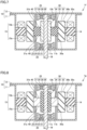
Fig. 1 is a schematic cross-sectional view of a motor in a first embodiment. -
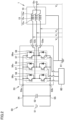
Fig. 2 is a schematic circuit diagram of the motor in the first embodiment connected to a current supply device. -
Fig. 3 is a schematic cross-sectional view of a motor in a second embodiment. -
Fig. 4 is a schematic cross-sectional view of a motor in a third embodiment. -
Fig. 5 is a schematic cross-sectional view of a motor in a fourth embodiment. -
Fig. 6 is a schematic cross-sectional view of a motor in a fifth embodiment. -
Fig. 7 is a schematic cross-sectional view of a motor in a sixth embodiment. -
Fig. 8 is a schematic cross-sectional view of a motor in a seventh embodiment. -
Fig. 9 is a schematic cross-sectional view of a motor in an eighth embodiment. - Embodiments of the present disclosure will be described below. The same configuration is denoted by the same reference number and a description thereof will not be repeated.
- Referring to
Fig. 1 andFig. 2 , amotor 1 in a first embodiment will be described. Referring toFig. 1 ,motor 1 mainly includes acase 10, astator core 14, acoil 15, aconductive shaft 18,bearings rotor core 30, andelectrostatic shields -
Case 10 containsstator core 14,coil 15,bearings rotor core 30, andelectrostatic shields Case 10 includes aframe 11 and abracket 12.Frame 11 includes a bottom wall and a side wall. Frame 11 (bottom wall) has ahole 11a. The bottom wall offrame 11 is a bottom wall ofcase 10, and the side wall offrame 11 is a side wall ofcase 10.Bracket 12 is opposed to the bottom wall offrame 11 and connected to the side wall offrame 11.Bracket 12 is a top wall ofcase 10.Case 10 includes a conductive case portion. In the present embodiment, both offrame 11 andbracket 12 are the conductive case portion. Both offrame 11 andbracket 12 are formed of, for example, a conductive material such as iron steel (for example, carbon steel such as S45C) or alloy steel (for example, stainless steel). -
Stator core 14 is formed of a magnetic material.Stator core 14 may be formed of, for example, a laminate of electrical steel sheets produced by adding silicon to iron or carbon steel.Stator core 14 is fixed to case 10 (frame 11). Specifically,stator core 14 is fixed to the side wall of case 10 (frame 11).Stator core 14 is opposed torotor core 30.Stator core 14 is spaced by a gap g fromrotor core 30 in the radial direction ofrotor core 30. Gap g is a gap between an outerperipheral side surface 30c ofrotor core 30 and an inner peripheral side surface ofstator core 14. Gap g is, for example, 500 µm or less.Stator core 14 surroundsrotor core 30. -
Coil 15 is wound aroundstator core 14.Coil 15 is spaced by a gap fromrotor core 30.Stator core 14 surroundsrotor core 30.Coil 15 includes afirst coil portion 15a and asecond coil portion 15b.First coil portion 15a is exposed fromstator core 14 and proximate to bearing 20 (the bottom wall offrame 11 or the bottom wall of case 10) in the axial direction ofconductive shaft 18.Second coil portion 15b is exposed fromstator core 14 and proximate to bearing 25 (bracket 12 or the top wall of case 10) in the axial direction ofconductive shaft 18. Referring toFig. 2 ,coil 15 includes, for example, au-phase coil 15u, a v-phase coil 15v, and a w-phase coil 15w. - Referring to
Fig. 1 ,conductive shaft 18 is formed of a conductive material such as iron steel (for example, carbon steel such as S45C).Conductive shaft 18 is spaced apart fromcase 10. Specifically,conductive shaft 18 penetrates the conductive case portion (frame 11) throughhole 11a.Conductive shaft 18 is spaced apart from the conductive case portion (frame 11, bracket 12). -
Bearings conductive shaft 18 rotatably relative to the conductive case portion (frame 11, bracket 12).Bearings outer rings inner rings elements insulative lubricants - Specifically,
frame 11 has asupport wall 11b extending in the axial direction ofconductive shaft 18.Bearing 20 supportsconductive shaft 18 rotatably relative to the conductive case portion (frame 11).Bearing 20 includesouter ring 22,inner ring 21, a plurality of rollingelements 23, andinsulative lubricant 24.Outer ring 22 is fixed to supportwall 11b.Conductive shaft 18 is press-fitted ininner ring 21.Inner ring 21 andouter ring 22 are formed of a conductive material such as iron steel (for example, carbon steel). A plurality of rollingelements 23 are disposed in a rollable manner betweenouter ring 22 andinner ring 21. A plurality of rollingelements 23 are formed of, for example, a conductive material such as iron steel (for example, carbon steel).Insulative lubricant 24 is, for example, grease or lubricating oil.Insulative lubricant 24 is sealed in a bearing space betweenouter ring 22 andinner ring 21. -
Bracket 12 has asupport wall 12b extending in the axial direction ofconductive shaft 18.Bearing 25 supportsconductive shaft 18 rotatably relative to the conductive case portion (bracket 12).Bearing 25 includesouter ring 27,inner ring 26, a plurality of rollingelements 28, andinsulative lubricant 29.Outer ring 27 is fixed to supportwall 12b.Conductive shaft 18 is press-fitted ininner ring 26.Inner ring 26 andouter ring 27 are formed of a conductive material such as iron steel (for example, carbon steel). A plurality of rollingelements 28 are disposed in a rollable manner betweenouter ring 27 andinner ring 26. A plurality of rollingelements 28 are formed of, for example, a conductive material such as iron steel (for example, carbon steel).Insulative lubricant 29 is, for example, grease or lubricating oil.Insulative lubricant 29 is sealed in a bearing space betweenouter ring 27 andinner ring 26. -
Rotor core 30 is fixed toconductive shaft 18.Rotor core 30 is formed of a magnetic material.Rotor core 30 includes a firstmain surface 30a proximate to bearing 20 (the bottom wall offrame 11 or the bottom wall of case 10), a secondmain surface 30b proximate to bearing 25 (bracket 12 or the top wall of case 10), and outerperipheral side surface 30c. Secondmain surface 30b is opposite to firstmain surface 30a. Outerperipheral side surface 30c is connected to firstmain surface 30a and to secondmain surface 30b. -
Rotor core 30 hasring grooves Ring groove 31a is formed betweencoil 15 andconductive shaft 18 in the radial direction ofrotor core 30. -
Ring groove 31a is formed in firstmain surface 30a ofrotor core 30.Ring groove 31a is formed betweenfirst coil portion 15a andconductive shaft 18 in the radial direction ofrotor core 30. A width W1 ofring groove 31a is larger than gap g betweenstator core 14 androtor core 30. Width W1 ofring groove 31a may be 1.0 mm or more. Therefore, a part ofelectrostatic shield 40 can be easily disposed inring groove 31a. The dimensional accuracy ofelectrostatic shield 40 can be relaxed. - A distance D1 between
ring groove 31a and outerperipheral side surface 30c ofrotor core 30 is, for example, 1.0 mm or more. Therefore, the gap betweenelectrostatic shield 40 and coil 15 (first coil portion 15a) is increased. The choices of materials ofelectrostatic shield 40 are increased. -
Ring groove 31b is formed in secondmain surface 30b ofrotor core 30.Ring groove 31b is formed betweensecond coil portion 15b andconductive shaft 18 in the radial direction ofrotor core 30. A width W2 ofring groove 31b is larger than gap g betweenstator core 14 androtor core 30. Width W2 ofring groove 31b may be 1.0 mm or more. Therefore, a part ofelectrostatic shield 45 can be easily disposed inring groove 31b. The dimensional accuracy ofelectrostatic shield 45 can be relaxed. - A distance D2 between
ring groove 31b and outerperipheral side surface 30c ofrotor core 30 is, for example, 1.0 mm or more. Therefore, the distance betweenelectrostatic shield 45 and coil 15 (second coil portion 15b) is increased. The choices of materials ofelectrostatic shield 45 are increased. -
Rotor core 30 includes afirst core portion 33 proximate tostator core 14 relative to ringgrooves second core portion 34 proximate toconductive shaft 18 relative to ringgrooves third core portion 35 betweenfirst core portion 33 andsecond core portion 34.First core portion 33,second core portion 34, andthird core portion 35 definering grooves third core portion 35 in the radial direction ofrotor core 30 corresponds to the positions ofring grooves rotor core 30. The height of third core portion 35 (the length ofthird core portion 35 in the axial direction of conductive shaft 18) is smaller than the height of first core portion 33 (the length offirst core portion 33 in the axial direction of conductive shaft 18) and smaller than the height of second core portion 34 (the length ofsecond core portion 34 in the axial direction of conductive shaft 18). -
First core portion 33 is betweencoil 15 andelectrostatic shields rotor core 30. Specifically,first core portion 33 is betweenfirst coil portion 15a andelectrostatic shield 40 in the radial direction ofrotor core 30.First core portion 33 is betweensecond coil portion 15b andelectrostatic shield 45 in the radial direction ofrotor core 30. -
Rotor core 30 is formed of a magnetic material. At least one offirst core portion 33,second core portion 34, orthird core portion 35 is formed of an insulative material. In the present embodiment,first core portion 33,second core portion 34, andthird core portion 35 are formed of a magnetic and insulative material containing resin. In other words, theentire rotor core 30 is formed of a magnetic and insulative material containing resin. Specifically, rotor core 30 (first core portion 33,second core portion 34, and third core portion 35) may be formed of a magnetic and insulative material in which an insulating resin material such as nylon, elastomer, or polyphenylenesulfide (PPS) and a magnetic material such as ferrite, neodymium, or samarium-cobalt alloy are mixed.Rotor core 30 can be produced, for example, by integrally molding a mixture of an insulating resin material and a magnetic material onconductive shaft 18. - Electrostatic shields 40 and 45 are formed of a conductive material such as aluminum alloy, copper, iron steel (for example, carbon steel such as S45C), or alloy steel (for example, stainless steel). Electrostatic shields 40 and 45 may be formed of a magnetic and conductive metal material such as iron steel (for example, carbon steel such as S45C) or alloy steel (for example, stainless steel). Electrostatic shields 40 and 45 may be formed of a non-magnetic and conductive metal material such as aluminum alloy or copper.
- Electrostatic shields 40 and 45 are fixed to the conductive case portion (
frame 11, bracket 12). Electrostatic shields 40 and 45 are electrically connected to the conductive case portion (frame 11, bracket 12). Specifically,electrostatic shield 40 is fixed to the conductive case portion (frame 11).Electrostatic shield 40 extends from the conductive case portion (frame 11) towardrotor core 30 along the axial direction ofconductive shaft 18.Electrostatic shield 40 is electrically connected to the conductive case portion (frame 11).Electrostatic shield 45 is fixed to the conductive case portion (bracket 12).Electrostatic shield 45 extends from the conductive case portion (bracket 12) towardrotor core 30 along the axial direction ofconductive shaft 18.Electrostatic shield 45 is electrically connected to the conductive case portion (bracket 12). - Electrostatic shields 40 and 45 have, for example, a cylindrical shape. Electrostatic shields 40 and 45 are disposed between
coil 15 andconductive shaft 18. Parts ofelectrostatic shields ring grooves rotor core 30,electrostatic shields coil 15 withfirst core portion 33 interposed. Electrostatic shields 40 and 45 shieldconductive shaft 18 from at least a part ofcoil 15. - Specifically,
electrostatic shield 40 is disposed betweenfirst coil portion 15a andconductive shaft 18. A part ofelectrostatic shield 40 is withinring groove 31a. In the radial direction ofrotor core 30,electrostatic shield 40 is opposed to at least a part offirst coil portion 15a withfirst core portion 33 interposed.Electrostatic shield 40 shields conductiveshaft 18 from at least a part offirst coil portion 15a. -
Electrostatic shield 45 is disposed betweensecond coil portion 15b andconductive shaft 18. A part ofelectrostatic shield 45 is withinring groove 31b. In the radial direction ofrotor core 30,electrostatic shield 45 is opposed to at least a part ofsecond coil portion 15b withfirst core portion 33 interposed.Electrostatic shield 45 shields conductiveshaft 18 from at least a part ofsecond coil portion 15b. - Referring to
Fig. 2 , in order to actuatemotor 1,motor 1 is connected to apower supply device 50.Power supply device 50 supplies, for example, an AC power such as three phase AC power tomotor 1.Power supply device 50 includes, for example, apower supply 51, a smoothingcapacitor 52, aninverter circuit 53, apositive electrode line 54, anegative electrode line 55, and acontrol circuit 60.Power supply 51 is connected topositive electrode line 54 andnegative electrode line 55.Power supply 51 is, for example, a DC power supply. Smoothingcapacitor 52 is connected topositive electrode line 54 andnegative electrode line 55. Smoothingcapacitor 52 stabilizes a DC power betweenpositive electrode line 54 andnegative electrode line 55. -
Inverter circuit 53 includes a positiveelectrode input terminal 53a, a negativeelectrode input terminal 53b,legs u-phase output terminal 53u, a v-phase output terminal 53v, and a w-phase output terminal 53w. Positiveelectrode input terminal 53a is connected topositive electrode line 54. Negativeelectrode input terminal 53b is connected tonegative electrode line 55.Legs electrode input terminal 53a and negativeelectrode input terminal 53b.Legs semiconductor switching element 57 such as an insulated gate bipolar transistor (IGBT) and a freewheelingdiode 58 connected in anti-parallel withsemiconductor switching element 57. - When
semiconductor switching element 57 is an IGBT, the collector terminal of the IGBT in the upper arm is connected to positiveelectrode input terminal 53a, and the emitter terminal of the IGBT in the lower arm is connected to negativeelectrode input terminal 53b.U-phase output terminal 53u is connected toleg 56u. V-phase output terminal 53v is connected toleg 56v. W-phase output terminal 53w is connected toleg 56w.U-phase coil 15u is connected tou-phase output terminal 53u. V-phase coil 15v is connected to v-phase output terminal 53v. W-phase coil 15w is connected to w-phase output terminal 53w. -
Control circuit 60 is connected to the gate terminal of each ofsemiconductor switching elements 57.Inverter circuit 53 is controlled bycontrol circuit 60, for example, by the pulse width modulation (PWM) method.Inverter circuit 53 converts a DC power input frompower supply 51 toinverter circuit 53 into a three phase AC power (u-phase AC power, v-phase AC power, w-phase AC power).Inverter circuit 53 outputs the three phase AC power tocoil 15. Specifically,inverter circuit 53 outputs u-phase AC power tou-phase coil 15u.Inverter circuit 53 outputs v-phase AC power to v-phase coil 15v.Inverter circuit 53 outputs w-phase AC power to w-phase coil 15w. The three phase AC power is supplied tocoil 15 to rotaterotor core 30 andconductive shaft 18 to whichrotor core 30 is fixed.Motor 1 is thus actuated. - Referring to
Fig. 1 andFig. 2 , a neutral point potential Vn which is a potential at aneutral point 15n ofcoil 15 during operation ofmotor 1 is the average value of voltage of three phase AC power (u-phase voltage Vu of u-phase AC power, v-phase voltage Vv of v-phase AC power, w-phase voltage Vw of w-phase AC power).Case 10 is connected to theground 61. Therefore, the potential difference betweencoil 15 andcase 10 during operation ofmotor 1 is the neutral point potential. - In
motor 1,coil 15 andconductive shaft 18 are capacitively coupled to each other.Conductive shaft 18 andcase 10 are capacitively coupled to each other. A first capacitor formed betweencoil 15 andconductive shaft 18 and a second capacitor formed betweenconductive shaft 18 andcase 10 can be considered as being present between the neutral point potential and theground 61, and the first capacitor and the second capacitor can be considered as being connected in parallel with each other. The potential difference betweencoil 15 andcase 10 is divided into a potential difference betweencoil 15 andconductive shaft 18 and a potential difference betweenconductive shaft 18 andcase 10, depending on a capacitance betweencoil 15 andconductive shaft 18 and a capacitance betweenconductive shaft 18 andcase 10. - Outer rings 22 and 27 of
bearings frame 11, bracket 12), andinner rings bearings conductive shaft 18. The potential difference betweenouter rings inner rings conductive shaft 18 andcase 10. When the shaft rotates at high speed during operation ofmotor 1, a lubricant film which is a part ofinsulative lubricants outer rings elements elements inner rings inner rings insulative lubricants - When the potential difference between
conductive shaft 18 andcase 10 exceeds a breakdown voltage ofinsulative lubricants outer rings inner rings outer rings inner rings inner rings outer rings elements bearings motor 1 is shortened. - In the present embodiment, at least one of
first core portion 33,second core portion 34, orthird core portion 35 is formed of an insulative material. Electrostatic shields 40 and 45 are disposed betweencoil 15 andconductive shaft 18. Electrostatic shields 40 and 45 are electrically connected tocase 10. Electrostatic shields 40 and 45 therefore can shieldconductive shaft 18 fromcoil 15. The capacitance betweencoil 15 andconductive shaft 18 is reduced. The potential difference betweencoil 15 andconductive shaft 18 during operation ofmotor 1 is increased, and the potential difference betweenconductive shaft 18 andcase 10 during operation ofmotor 1 is reduced. The potential difference betweenconductive shaft 18 andcase 10 during operation ofmotor 1 becomes smaller than the breakdown voltage ofinsulative lubricants insulative lubricants motor 1 is prevented. Flowing of shaft current betweenouter rings inner rings inner rings outer rings elements bearings motor 1 can be prolonged. - In a modification of the present embodiment, one of
frame 11 andbracket 12 may be formed of a conductive material, and the other offrame 11 andbracket 12 may be formed of an insulative material (for example, an insulating resin material such as polybutylene terephthalate (PBT)). In other words, one offrame 11 andbracket 12 is the conductive case portion, but the other offrame 11 andbracket 12 is not necessarily the conductive case portion. - The effects of
motor 1 in the present embodiment will be described. -
Motor 1 in the present embodiment includescase 10,conductive shaft 18, a bearing (bearing 20, bearing 25, or both of bearing 20 and bearing 25),rotor core 30,stator core 14,coil 15, and an electrostatic shield (for example,electrostatic shield 40,electrostatic shield 45, or both ofelectrostatic shield 40 and electrostatic shield 45).Case 10 includes a conductive case portion (for example,frame 11,bracket 12, or both offrame 11 and bracket 12).Conductive shaft 18 is spaced apart fromcase 10.Bearing conductive shaft 18 rotatably relative to the conductive case portion.Rotor core 30 is fixed toconductive shaft 18.Stator core 14 is opposed torotor core 30.Coil 15 is wound aroundstator core 14. The electrostatic shield is fixed to the conductive case portion.Case 10 contains the bearing,rotor core 30,stator core 14,coil 15, and the electrostatic shield. The bearing includes a conductive outer ring (for example,outer ring 22,outer ring 27, or both ofouter ring 22 and outer ring 27), a conductive inner ring (for example,inner ring 21,inner ring 26, or both ofinner ring 21 and inner ring 26), a plurality of rolling elements (for example, a plurality of rollingelements 23, a plurality of rollingelements 28, or both of a plurality of rollingelements 23 and a plurality of rolling elements 28), and an insulative lubricant (insulative lubricant 24,insulative lubricant 29, or both ofinsulative lubricant 24 and insulative lubricant 29). The conductive outer ring is fixed to the conductive case portion. The conductive inner ring is fixed toconductive shaft 18. The rolling elements are disposed in a rollable manner between the conductive outer ring and the conductive inner ring. The insulative lubricant is sealed in a bearing space between the conductive outer ring and the conductive inner ring.Rotor core 30 has a ring groove (ring groove 31a,ring groove 31b, or both ofring groove 31a andring groove 31b).Rotor core 30 includesfirst core portion 33 proximate tostator core 14 relative to the ring groove,second core portion 34 proximate toconductive shaft 18 relative to the ring groove (ring groove 31a,ring groove 31b, or both ofring groove 31a andring groove 31b), andthird core portion 35 betweenfirst core portion 33 andsecond core portion 34. At least one offirst core portion 33,second core portion 34, orthird core portion 35 is formed of an insulative material. The electrostatic shield is disposed betweencoil 15 andconductive shaft 18 and electrically connected to the conductive case portion. A part of the electrostatic shield is within the ring groove. - The electrostatic shield (for example,
electrostatic shield 40,electrostatic shield 45, or both ofelectrostatic shield 40 and electrostatic shield 45) can shieldconductive shaft 18 fromcoil 15. The capacitance betweencoil 15 andconductive shaft 18 is reduced. The potential difference betweencoil 15 andconductive shaft 18 during operation ofmotor 1 is increased, and the potential difference betweenconductive shaft 18 andcase 10 during operation ofmotor 1 is reduced. Dielectric breakdown of the insulative lubricant (insulative lubricant 24,insulative lubricant 29, or both ofinsulative lubricant 24 and insulative lubricant 29) during operation ofmotor 1 is prevented. Flowing of shaft current between the outer ring (for example,outer ring 22,outer ring 27, or both ofouter ring 22 and outer ring 27) and the inner ring (for example,inner ring 21,inner ring 26, or both ofinner ring 21 and inner ring 26) is prevented. Occurrence of electric corrosion in the inner ring, the outer ring, and a plurality of rolling elements (for example, a plurality of rollingelements 23, a plurality of rollingelements 28, or both of a plurality of rollingelements 23 and a plurality of rolling elements 28) can be prevented. - Furthermore, since a part of the electrostatic shield (for example,
electrostatic shield 40,electrostatic shield 45, or both ofelectrostatic shield 40 and electrostatic shield 45) is within the ring groove (ring groove 31a,ring groove 31b, or both ofring groove 31a andring groove 31b), the gap between the electrostatic shield andcoil 15 can be increased. Not only a non-magnetic material but also a magnetic material can be selected as the electrostatic shield. The choices of materials of the electrostatic shield can be increased. - In
motor 1 in the present embodiment, the electrostatic shield (for example,electrostatic shield 40,electrostatic shield 45, or both ofelectrostatic shield 40 and electrostatic shield 45) is formed of a magnetic and conductive metal material. Thus, the choices of materials of the electrostatic shield can be increased. - In
motor 1 in the present embodiment, the electrostatic shield (for example,electrostatic shield 40,electrostatic shield 45, or both ofelectrostatic shield 40 and electrostatic shield 45) is formed of a non-magnetic and conductive metal material. - Thus, adverse effects of the electrostatic shield on a distribution of magnetic field formed by
coil 15 can be prevented. Reduction in electromagnetic force acting onrotor core 30 can be prevented. Further, occurrence of eddy current in the electrostatic shield due to a magnetic field formed bycoil 15 can be prevented. Occurrence of eddy current loss inmotor 1 can be avoided. In this way, reduction in efficiency ofmotor 1 can be prevented. - In
motor 1 in the present embodiment, the width of the ring groove (ring groove 31a,ring groove 31b, or both ofring groove 31a andring groove 31b) is greater than a first gap (gap g) betweenstator core 14 androtor core 30. - Thus, the dimensional accuracy and alignment accuracy of the electrostatic shield (for example,
electrostatic shield 40,electrostatic shield 45, or both ofelectrostatic shield 40 and electrostatic shield 45) can be relaxed. The productivity ofmotor 1 is improved and the cost ofmotor 1 can be reduced. - In
motor 1 in the present embodiment, the width of the ring groove (ring groove 31a,ring groove 31b, or both ofring groove 31a andring groove 31b) is 1.0 mm or more. - Thus, the dimensional accuracy and alignment accuracy of the electrostatic shield (for example,
electrostatic shield 40,electrostatic shield 45, or both ofelectrostatic shield 40 and electrostatic shield 45) can be relaxed. The productivity ofmotor 1 is improved and the cost ofmotor 1 can be reduced. - In
motor 1 in the present embodiment,first core portion 33,second core portion 34, andthird core portion 35 are formed of a magnetic and insulative material containing resin. -
First core portion 33,second core portion 34, andthird core portion 35 are all formed of a magnetic and insulative material containing resin. Thus,first core portion 33,second core portion 34, andthird core portion 35 can be formed in a batch. The cost ofmotor 1 can be reduced. - Referring to
Fig. 3 , amotor 1b in a second embodiment will be described.Motor 1b in the present embodiment includes a configuration similar tomotor 1 in the first embodiment and achieves similar effects, but differs mainly in the following points. - In
motor 1b,electrostatic shields holes holes rotor core 30. Electrostatic shields 40 and 45 have throughholes holes rotor core 30. A coolant (for example, air, water, or oil) incase 10 can pass through the throughholes holes case 10.Coil 15,rotor core 30, andstator core 14 can be efficiently cooled by the coolant. -
Motor 1b in the present embodiment achieves the following effects in addition to the effects ofmotor 1 in the first embodiment. - In
motor 1b in the present embodiment, the electrostatic shield (for example,electrostatic shield 40,electrostatic shield 45, or both ofelectrostatic shield 40 and electrostatic shield 45) has a through hole (for example, throughhole 41, throughhole 46, or both of throughhole 41 and through hole 46). - Thus, the coolant in case 10 (for example, air, water, or oil) can pass through the through hole (for example, through
hole 41, throughhole 46, or both of throughhole 41 and through hole 46).Coil 15,rotor core 30, andstator core 14 can be efficiently cooled by the coolant. Deterioration ofcoil 15 and change in magnetic characteristics ofstator core 14 and magnetic characteristics ofrotor core 30 due to heat generated incoil 15 can be suppressed. Reduction in performance ofmotor 1b is prevented, and the lifetime ofmotor 1b can be prolonged. - Referring to
Fig. 4 , amotor 1c in a third embodiment will be described.Motor 1c in the present embodiment includes a configuration similar tomotor 1 in the first embodiment but differs mainly in the following points. - In
motor 1c, a height Hi ofelectrostatic shield 40 from the conductive case portion (frame 11) is equal to a gap Gi between the conductive case portion (frame 11) andstator core 14 or greater than gap Gi. Thus,electrostatic shield 40 can shieldconductive shaft 18 from the entirefirst coil portion 15a. A height H2 ofelectrostatic shield 45 from the conductive case portion (bracket 12) is equal to a gap G2 between the conductive case portion (bracket 12) andstator core 14 or greater than gap G2. Thus,electrostatic shield 45 can shieldconductive shaft 18 from the entiresecond coil portion 15b. -
Motor 1c in the present embodiment achieves the following effects in addition to the effects ofmotor 1 in the first embodiment. - In
motor 1c in the present embodiment,stator core 14 is formed of a magnetic and insulative material. The height (height Hi, height H2) of the electrostatic shield (electrostatic shield 40,electrostatic shield 45, or both ofelectrostatic shield 40 and electrostatic shield 45) from the conductive case portion (frame 11,bracket 12, or both offrame 11 and bracket 12) is equal to or greater than a second gap (gap G1, gap G2) between the conductive case portion andstator core 14. - Thus, the electrostatic shield (
electrostatic shield 40,electrostatic shield 45, or both ofelectrostatic shield 40 and electrostatic shield 45) can shieldconductive shaft 18 from the entire portion ofcoil 15 that is exposed from stator core 14 (first core portion 33, second core portion 34). The capacitance betweencoil 15 andconductive shaft 18 is further reduced. The potential difference betweenconductive shaft 18 andcase 10 during operation ofmotor 1c is further reduced. Flowing of shaft current between the outer ring (outer ring 22,outer ring 27, or both ofouter ring 22 and outer ring 27) and the inner ring (inner ring 21,inner ring 26, or both ofinner ring 21 and inner ring 26) is further prevented. Occurrence of electric corrosion in the inner ring, the outer ring, and a plurality of rolling elements (a plurality of rollingelements 23, a plurality of rollingelements 28, or both of a plurality of rollingelements 23 and a plurality of rolling elements 28) can be further prevented. - Referring to
Fig. 5 , amotor 1d in a fourth embodiment will be described.Motor 1d in the present embodiment includes a configuration similar tomotor 1c in the third embodiment but differs mainly in the following points. - In
motor 1d, a gap r1 between coil 15 (first coil portion 15a) andelectrostatic shield 40 is greater than a gap R1 betweenelectrostatic shield 40 andconductive shaft 18. Gap r1 may be, for example, 1.2 or more times as large as gap R1, may be 1.5 or more times as large as gap R1, or may be 2.0 or more times as large as gap R1. Thus, the capacitance betweencoil 15 andconductive shaft 18 is further reduced. - A gap r2 between coil 15 (
second coil portion 15b) andelectrostatic shield 45 is greater than a gap R2 betweenelectrostatic shield 45 andconductive shaft 18. Gap r2 may be, for example, 1.2 or more times as large as gap R2, may be 1.5 or more times as large as gap R2, or may be 2.0 or more times as large as gap R2. Thus, the capacitance betweencoil 15 andconductive shaft 18 is further reduced. - In a modification of the present embodiment, in a motor in another embodiment (for example,
motor 1 in the first embodiment), gap r1 between coil 15 (first coil portion 15a) andelectrostatic shield 40 may be greater than gap R1 betweenelectrostatic shield 40 andconductive shaft 18, and gap r2 between coil 15 (second coil portion 15b) andelectrostatic shield 45 may be greater than gap R2 betweenelectrostatic shield 45 andconductive shaft 18. -
Motor 1d in the present embodiment achieves the following effects in addition to the effects ofmotor 1c in the third embodiment. - In
motor 1d in the present embodiment, a third gap (gap r1, gap r2, or both of gap r1 and gap r2) betweencoil 15 and the electrostatic shield (electrostatic shield 40,electrostatic shield 45, or both ofelectrostatic shield 40 and electrostatic shield 45) is greater than a fourth gap (gap R1, gap R2, or both of gap R1 and gap R2) between the electrostatic shield andconductive shaft 18. - Thus, the capacitance between
coil 15 andconductive shaft 18 is further reduced. The potential difference betweenconductive shaft 18 andcase 10 during operation ofmotor 1d is further reduced. Flowing of shaft current between the outer ring (outer ring 22,outer ring 27, or both ofouter ring 22 and outer ring 27) and the inner ring (inner ring 21,inner ring 26, or both ofinner ring 21 and inner ring 26) is further prevented. Occurrence of electric corrosion in the inner ring, the outer ring, and a plurality of rolling elements (a plurality of rollingelements 23, a plurality of rollingelements 28, or both of a plurality of rollingelements 23 and a plurality of rolling elements 28) can be further prevented. - Referring to
Fig. 6 , amotor 1e in a fifth embodiment will be described.Motor 1e in the present embodiment includes a configuration similar tomotor 1 in the first embodiment but differs mainly in the following points. - In
motor 1e, bearing 20 is fixed to the conductive case portion (frame 11) viaelectrostatic shield 40. Specifically,outer ring 22 is fixed toelectrostatic shield 40.Support wall 11b (seeFig. 1 ) is omitted. -
Bearing 25 is fixed to the conductive case portion (bracket 12) viaelectrostatic shield 45. Specifically,outer ring 27 is fixed toelectrostatic shield 45.Support wall 12b (seeFig. 1 ) is omitted. -
Motor 1e in the present embodiment achieves the following effects in addition to the effects ofmotor 1 in the first embodiment. - In
motor 1e in the present embodiment, the bearing (bearing 20, bearing 25, or both of bearing 20 and bearing 25) is fixed to the conductive case portion (frame 11,bracket 12, or both offrame 11 and bracket 12) via the electrostatic shield (electrostatic shield 40,electrostatic shield 45, or both ofelectrostatic shield 40 and electrostatic shield 45). Thus,motor 1e can be downsized. - Referring to
Fig. 7 , amotor 1f in a sixth embodiment will be described.Motor 1f in the present embodiment includes a configuration similar tomotor 1 in the first embodiment but differs mainly in the following points. - In
motor 1f,second core portion 34 is formed of a magnetic and conductive metal material such as iron steel (for example, carbon steel such as S45C) or alloy steel (for example, stainless steel).Third core portion 35 is formed of a magnetic and insulative material containing resin.Third core portion 35 may be formed of a magnetic and insulative material in which an insulating resin material such as nylon, elastomer, or polyphenylenesulfide (PPS) and a magnetic material such as ferrite, neodymium, or samarium-cobalt alloy are mixed. - In the present embodiment,
rotor core 30 can be formed, for example, by the following steps.Second core portion 34 is press-fitted onconductive shaft 18. Then, the shaft andsecond core portion 34 are placed in a mold (not shown). A mixture of an insulating resin material and a magnetic material is injected into the mold. The mixture of an insulating resin material and a magnetic material is integrally molded onsecond core portion 34 to formfirst core portion 33 andthird core portion 35. -
Motor 1f in the present embodiment achieves the following effects in addition to the effects ofmotor 1 in the first embodiment. - In
motor 1f in the present embodiment,second core portion 34 is formed of a magnetic and conductive metal material.First core portion 33 andthird core portion 35 are formed of a magnetic and insulative material containing resin. -
Second core portion 34 can protectconductive shaft 18 from heat shock that occurs whenfirst core portion 33 andthird core portion 35 formed of a magnetic and insulative material containing resin are integrally molded onsecond core portion 34. Breakage ofconductive shaft 18 during use ofmotor 1f can be prevented. The lifetime ofmotor 1f can be prolonged. - Referring to
Fig. 8 , amotor 1g in a seventh embodiment will be described.Motor 1g in the present embodiment includes a configuration similar tomotor 1 in the first embodiment but differs mainly in the following points. - In
motor 1g,second core portion 34 is formed of a magnetic and insulative material containing resin.Second core portion 34 may be formed of, for example, a magnetic and insulative material in which an insulating resin material such as nylon, elastomer, or polyphenylenesulfide (PPS) and a magnetic material such as ferrite, neodymium, or samarium-cobalt alloy are mixed.Third core portion 35 is formed of a magnetic and conductive metal material such as iron steel (for example, carbon steel such as S45C) or alloy steel (for example, stainless steel). - The height of third core portion 35 (the length of
third core portion 35 in the axial direction of conductive shaft 18) is smaller than the height of first core portion 33 (the length offirst core portion 33 in the axial direction of conductive shaft 18) and smaller than the height of second core portion 34 (the length ofsecond core portion 34 in the axial direction of conductive shaft 18). Thus,third core portion 35 is more likely to be broken thanfirst core portion 33 andsecond core portion 34 by centrifugal force acting onrotor core 30 during operation ofmotor 1g. However,first core portion 33 andsecond core portion 34 are formed of a magnetic and insulative material containing resin, whereasthird core portion 35 is formed of a magnetic and conductive metal material.Third core portion 35 is formed of a material having a higher mechanical strength thanfirst core portion 33 andsecond core portion 34. Thus, breakage ofthird core portion 35 by centrifugal force acting onrotor core 30 during operation ofmotor 1g can be prevented. - In the present embodiment,
rotor core 30 can be formed, for example, by the following steps.Conductive shaft 18 andthird core portion 35 are placed in a mold (not shown). Then, a mixture of an insulating resin material and a magnetic material is injected into the mold. The mixture of an insulating resin material and a magnetic material is integrally molded on the shaft andthird core portion 35 to formfirst core portion 33 andsecond core portion 34. -
Motor 1g in the present embodiment achieves the following effects in addition to the effects ofmotor 1 in the first embodiment. - In
motor 1g in the present embodiment,first core portion 33 andsecond core portion 34 are formed of a magnetic and insulative material containing resin.Third core portion 35 is formed of a magnetic and conductive metal material. - Breakage of
third core portion 35 can be prevented. The lifetime ofmotor 1g can be prolonged. - Referring to
Fig. 9 , amotor 1h in an eighth embodiment will be described.Motor 1h in the present embodiment includes a configuration similar tomotor 1 in the first embodiment but differs mainly in the following points. - In
motor 1h,second core portion 34 andthird core portion 35 are formed of a magnetic and conductive metal material such as iron steel (for example, carbon steel such as S45C), alloy steel (for example, stainless steel), or electrical steel sheets. Also in the present embodiment, similar to the seventh embodiment,third core portion 35 is formed of a magnetic and conductive metal material. Thus, breakage ofthird core portion 35 by centrifugal force acting onrotor core 30 during operation ofmotor 1h can be prevented. - In the present embodiment,
rotor core 30 can be formed, for example, by the following steps.Second core portion 34 andthird core portion 35 are press-fitted onconductive shaft 18. Then, the shaft,second core portion 34, andthird core portion 35 are placed in a mold (not shown). A mixture of an insulating resin material and a magnetic material is injected into the mold. The mixture of an insulating resin material and a magnetic material is integrally molded onthird core portion 35 to formfirst core portion 33. -
Motor 1h in the present embodiment achieves the following effects in addition to the effects ofmotor 1 in the first embodiment. - In
motor 1h in the present embodiment,first core portion 33 is formed of a magnetic and insulative material containing resin.Second core portion 34 andthird core portion 35 are formed of a magnetic and conductive metal material. - Thus, breakage of
third core portion 35 can be prevented. The lifetime ofmotor 1h can be prolonged. Further,second core portion 34 andthird core portion 35 can protectconductive shaft 18 from heat shock that occurs whenfirst core portion 33 formed of a magnetic and insulative material containing resin is integrally molded onthird core portion 35. Breakage ofconductive shaft 18 during use ofmotor 1h can be prevented. The lifetime ofmotor 1h can be prolonged. - The first to eighth embodiments and modifications thereof disclosed here should be understood as being illustrative rather than being limitative in all respects. At least two of the first to eighth embodiments and modifications thereof disclosed here may be combined in a consistent manner. The scope of the present disclosure is shown not in the foregoing description but in the claims, and it is intended that all modifications that come within the meaning and range of equivalence to the claims are embraced here.
- 1, 1b, 1c, 1d, 1e, 1f, 1g, 1h motor, 10 case, 11 frame, 11a hole, 11b, 12b support wall, 12 bracket, 14 stator core, 15 coil, 15u u-phase coil, 15v v-phase coil, 15w w-phase coil, 15a first coil portion, 15b second coil portion, 15n neutral point, 18 conductive shaft, 20, 25 bearing, 21, 26 inner ring, 22, 27 outer ring, 23, 28 rolling element, 24, 29 insulative lubricant, 30 rotor core, 30a first main surface, 30b second main surface, 30c outer peripheral side surface, 31a, 31b ring groove, 33 first core portion, 34 second core portion, 35 third core portion, 40, 45 electrostatic shield, 41, 46 through hole, 50 power supply device, 51 power supply, 52 smoothing capacitor, 53 inverter circuit, 53a positive electrode input terminal, 53b negative electrode input terminal, 53u u-phase output terminal, 53v v-phase output terminal, 53w w-phase output terminal, 54 positive electrode line, 55 negative electrode line, 56u, 56v, 56w leg, 57 semiconductor switching element, 58 freewheeling diode, 60 control circuit, 61 ground.
Claims (13)
- A motor comprising:a case including a conductive case portion;a conductive shaft spaced apart from the case;a bearing supporting the conductive shaft rotatably relative to the conductive case portion;a rotor core fixed to the conductive shaft;a stator core opposed to the rotor core;a coil wound around the stator core; andan electrostatic shield fixed to the conductive case portion, whereinthe case contains the bearing, the rotor core, the stator core, the coil, and the electrostatic shield,the bearing includes a conductive outer ring, a conductive inner ring, a plurality of rolling elements, and an insulative lubricant, the conductive outer ring being fixed to the conductive case portion, the conductive inner ring being fixed to the conductive shaft, the rolling elements being disposed in a rollable manner between the conductive outer ring and the conductive inner ring, the insulative lubricant being sealed in a bearing space between the conductive outer ring and the conductive inner ring,the rotor core has a ring groove,the rotor core includes a first core portion proximate to the stator core relative to the ring groove, a second core portion proximate to the conductive shaft relative to the ring groove, and a third core portion between the first core portion and the second core portion,at least one of the first core portion, the second core portion, or the third core portion is formed of an insulative material,the electrostatic shield is disposed between the coil and the conductive shaft and electrically connected to the conductive case portion, anda part of the electrostatic shield is within the ring groove.
- The motor according to claim 1, wherein the electrostatic shield is formed of a magnetic and conductive metal material.
- The motor according to claim 1, wherein the electrostatic shield is formed of a non-magnetic and conductive metal material.
- The motor according to any one of claims 1 to 3, wherein a width of the ring groove is greater than a first gap between the stator core and the rotor core.
- The motor according to claim 4, wherein the width of the ring groove is 1.0 mm or more.
- The motor according to any one of claims 1 to 5, wherein the electrostatic shield has a through hole.
- The motor according to any one of claims 1 to 6, whereinthe stator core is formed of a magnetic and insulative material, anda height of the electrostatic shield from the conductive case portion is equal to or greater than a second gap between the conductive case portion and the stator core.
- The motor according to any one of claims 1 to 7, wherein a third gap between the coil and the electrostatic shield is greater than a fourth gap between the electrostatic shield and the conductive shaft.
- The motor according to any one of claims 1 to 8, wherein the bearing is fixed to the conductive case portion via the electrostatic shield.
- The motor according to any one of claims 1 to 9, wherein the first core portion, the second core portion, and the third core portion are formed of a magnetic and insulative material containing resin.
- The motor according to any one of claims 1 to 9, whereinthe second core portion is formed of a magnetic and conductive metal material, andthe first core portion and the third core portion are formed of a magnetic and insulative material containing resin.
- The motor according to any one of claims 1 to 9, whereinthe first core portion and the second core portion are formed of a magnetic and insulative material containing resin, andthe third core portion is formed of a magnetic and conductive metal material.
- The motor according to any one of claims 1 to 9, whereinthe first core portion is formed of a magnetic and insulative material containing resin, andthe second core portion and the third core portion are formed of a magnetic and conductive metal material.
Applications Claiming Priority (1)
| Application Number | Priority Date | Filing Date | Title |
|---|---|---|---|
| PCT/JP2021/018231 WO2022239190A1 (en) | 2021-05-13 | 2021-05-13 | Motor |
Publications (2)
| Publication Number | Publication Date |
|---|---|
| EP4340186A1 true EP4340186A1 (en) | 2024-03-20 |
| EP4340186A4 EP4340186A4 (en) | 2024-07-17 |
Family
ID=84028533
Family Applications (1)
| Application Number | Title | Priority Date | Filing Date |
|---|---|---|---|
| EP21941923.1A Withdrawn EP4340186A4 (en) | 2021-05-13 | 2021-05-13 | ENGINE |
Country Status (5)
| Country | Link |
|---|---|
| US (1) | US20240250578A1 (en) |
| EP (1) | EP4340186A4 (en) |
| JP (1) | JP7665019B2 (en) |
| CN (1) | CN117397150A (en) |
| WO (1) | WO2022239190A1 (en) |
Families Citing this family (2)
| Publication number | Priority date | Publication date | Assignee | Title |
|---|---|---|---|---|
| US12212189B2 (en) * | 2020-07-31 | 2025-01-28 | Mitsubishi Electric Corporation | Rotating electrical machine |
| WO2025215793A1 (en) * | 2024-04-11 | 2025-10-16 | 三菱電機株式会社 | Rotary electric machine and rotary electric machine system |
Family Cites Families (9)
| Publication number | Priority date | Publication date | Assignee | Title |
|---|---|---|---|---|
| JP3626869B2 (en) | 1999-03-19 | 2005-03-09 | 松下エコシステムズ株式会社 | Rotating electric machine |
| JP2008160909A (en) * | 2006-12-21 | 2008-07-10 | Nsk Ltd | Motor with built-in detector |
| JP5091905B2 (en) | 2008-11-06 | 2012-12-05 | 愛三工業株式会社 | Motor structure with resolver |
| JP4935799B2 (en) | 2008-11-17 | 2012-05-23 | 株式会社デンソー | Rotating electric machine and its rotor |
| JP5299074B2 (en) * | 2009-05-13 | 2013-09-25 | パナソニック株式会社 | Motor, generator, blower and wind power generator |
| JP5710886B2 (en) | 2010-03-15 | 2015-04-30 | 株式会社日本自動車部品総合研究所 | Rotating electric machine |
| WO2014039954A1 (en) * | 2012-09-07 | 2014-03-13 | Remy Technologies, Llc | Variable reluctance resolver having integral electromagnetic interference shield and rotary electric machine having same |
| US10938280B2 (en) * | 2013-11-01 | 2021-03-02 | Tesla, Inc. | Flux shield for electric motor |
| CN112366880B (en) * | 2019-07-26 | 2023-11-21 | 广东威灵电机制造有限公司 | Motors and electrical equipment with such motors |
-
2021
- 2021-05-13 EP EP21941923.1A patent/EP4340186A4/en not_active Withdrawn
- 2021-05-13 JP JP2023520686A patent/JP7665019B2/en active Active
- 2021-05-13 US US18/289,976 patent/US20240250578A1/en active Pending
- 2021-05-13 CN CN202180097970.6A patent/CN117397150A/en not_active Withdrawn
- 2021-05-13 WO PCT/JP2021/018231 patent/WO2022239190A1/en not_active Ceased
Also Published As
| Publication number | Publication date |
|---|---|
| EP4340186A4 (en) | 2024-07-17 |
| US20240250578A1 (en) | 2024-07-25 |
| WO2022239190A1 (en) | 2022-11-17 |
| JP7665019B2 (en) | 2025-04-18 |
| CN117397150A (en) | 2024-01-12 |
| JPWO2022239190A1 (en) | 2022-11-17 |
Similar Documents
| Publication | Publication Date | Title |
|---|---|---|
| US7230363B2 (en) | Low profile generator configuration | |
| JP6771537B2 (en) | Axial gap type rotary electric machine | |
| US9154020B2 (en) | Axial gap rotating-electric machine | |
| US10340770B2 (en) | Stator unit, motor, and parallel fan | |
| US20130323093A1 (en) | Motor and fan | |
| US20190131852A1 (en) | Motor | |
| EP3961873B1 (en) | Motor and electrical equipment having same | |
| EP4340186A1 (en) | Motor | |
| US11056953B2 (en) | Stator unit, motor, and fan motor | |
| KR20150062117A (en) | Motor and method for manufacturing the same | |
| EP3518389A1 (en) | Permanent magnet motor | |
| CN114928213A (en) | Electrical machine with ground shield | |
| CN120958702A (en) | A motor having a shielding structure for reducing capacitive coupling in the motor and an axial flux motor having the shielding structure. | |
| KR102687210B1 (en) | Brushless motor and electrics | |
| KR101503062B1 (en) | Brushless electric device with stop shaft and method of manufacturing the same | |
| JP5634438B2 (en) | Electric motor rotor, electric motor, air conditioner, and method of manufacturing electric motor rotor | |
| US12134302B2 (en) | Device for driving a compressor, and method for manufacturing the device | |
| EP2717436B1 (en) | Rotor of rotating electrical machine, and rotating electrical machine provided with same | |
| KR102565400B1 (en) | dc brushless motor | |
| JP2015023751A (en) | Electric motor and electrical machine | |
| WO2003043164A1 (en) | Dynamo-electric machine | |
| KR20170086918A (en) | BUSBAR assembly, motor and vehicle having the same | |
| JP2014230361A (en) | Rotor for motor, motor, air conditioner, and manufacturing method of rotor for motor | |
| JP7267238B2 (en) | electrical equipment | |
| JP2014187754A (en) | Rotor of motor, motor, air conditioner, and method of manufacturing rotor of motor |
Legal Events
| Date | Code | Title | Description |
|---|---|---|---|
| STAA | Information on the status of an ep patent application or granted ep patent |
Free format text: STATUS: THE INTERNATIONAL PUBLICATION HAS BEEN MADE |
|
| PUAI | Public reference made under article 153(3) epc to a published international application that has entered the european phase |
Free format text: ORIGINAL CODE: 0009012 |
|
| STAA | Information on the status of an ep patent application or granted ep patent |
Free format text: STATUS: REQUEST FOR EXAMINATION WAS MADE |
|
| 17P | Request for examination filed |
Effective date: 20231102 |
|
| AK | Designated contracting states |
Kind code of ref document: A1 Designated state(s): AL AT BE BG CH CY CZ DE DK EE ES FI FR GB GR HR HU IE IS IT LI LT LU LV MC MK MT NL NO PL PT RO RS SE SI SK SM TR |
|
| A4 | Supplementary search report drawn up and despatched |
Effective date: 20240618 |
|
| RIC1 | Information provided on ipc code assigned before grant |
Ipc: H02K 5/22 20060101ALN20240612BHEP Ipc: H02K 11/01 20160101ALI20240612BHEP Ipc: H02K 7/08 20060101ALI20240612BHEP Ipc: H02K 5/173 20060101ALI20240612BHEP Ipc: H02K 1/30 20060101ALI20240612BHEP Ipc: H02K 5/00 20060101AFI20240612BHEP |
|
| DAV | Request for validation of the european patent (deleted) | ||
| DAX | Request for extension of the european patent (deleted) | ||
| STAA | Information on the status of an ep patent application or granted ep patent |
Free format text: STATUS: EXAMINATION IS IN PROGRESS |
|
| 17Q | First examination report despatched |
Effective date: 20250403 |
|
| GRAP | Despatch of communication of intention to grant a patent |
Free format text: ORIGINAL CODE: EPIDOSNIGR1 |
|
| STAA | Information on the status of an ep patent application or granted ep patent |
Free format text: STATUS: GRANT OF PATENT IS INTENDED |
|
| RIC1 | Information provided on ipc code assigned before grant |
Ipc: H02K 5/00 20060101AFI20251015BHEP Ipc: H02K 1/30 20060101ALI20251015BHEP Ipc: H02K 5/173 20060101ALI20251015BHEP Ipc: H02K 7/08 20060101ALI20251015BHEP Ipc: H02K 11/01 20160101ALI20251015BHEP Ipc: H02K 5/22 20060101ALN20251015BHEP |
|
| RIC1 | Information provided on ipc code assigned before grant |
Ipc: H02K 5/00 20060101AFI20251021BHEP Ipc: H02K 1/30 20060101ALI20251021BHEP Ipc: H02K 5/173 20060101ALI20251021BHEP Ipc: H02K 7/08 20060101ALI20251021BHEP Ipc: H02K 11/01 20160101ALI20251021BHEP Ipc: H02K 5/22 20060101ALN20251021BHEP |
|
| INTG | Intention to grant announced |
Effective date: 20251030 |
|
| STAA | Information on the status of an ep patent application or granted ep patent |
Free format text: STATUS: THE APPLICATION HAS BEEN WITHDRAWN |
|
| 18W | Application withdrawn |
Effective date: 20260114 |