EP4340115A1 - Separator comprising organic/inorganic composite porous coating layer for electrochemical device and electrochemical device including same - Google Patents
Separator comprising organic/inorganic composite porous coating layer for electrochemical device and electrochemical device including same Download PDFInfo
- Publication number
- EP4340115A1 EP4340115A1 EP22887467.3A EP22887467A EP4340115A1 EP 4340115 A1 EP4340115 A1 EP 4340115A1 EP 22887467 A EP22887467 A EP 22887467A EP 4340115 A1 EP4340115 A1 EP 4340115A1
- Authority
- EP
- European Patent Office
- Prior art keywords
- separator
- coating layer
- electrochemical device
- organic
- porous coating
- Prior art date
- Legal status (The legal status is an assumption and is not a legal conclusion. Google has not performed a legal analysis and makes no representation as to the accuracy of the status listed.)
- Granted
Links
Images


Classifications
-
- H—ELECTRICITY
- H01—ELECTRIC ELEMENTS
- H01G—CAPACITORS; CAPACITORS, RECTIFIERS, DETECTORS, SWITCHING DEVICES, LIGHT-SENSITIVE OR TEMPERATURE-SENSITIVE DEVICES OF THE ELECTROLYTIC TYPE
- H01G11/00—Hybrid capacitors, i.e. capacitors having different positive and negative electrodes; Electric double-layer [EDL] capacitors; Processes for the manufacture thereof or of parts thereof
- H01G11/52—Separators
-
- H—ELECTRICITY
- H01—ELECTRIC ELEMENTS
- H01M—PROCESSES OR MEANS, e.g. BATTERIES, FOR THE DIRECT CONVERSION OF CHEMICAL ENERGY INTO ELECTRICAL ENERGY
- H01M50/00—Constructional details or processes of manufacture of the non-active parts of electrochemical cells other than fuel cells, e.g. hybrid cells
- H01M50/40—Separators; Membranes; Diaphragms; Spacing elements inside cells
- H01M50/409—Separators, membranes or diaphragms characterised by the material
- H01M50/411—Organic material
- H01M50/414—Synthetic resins, e.g. thermoplastics or thermosetting resins
- H01M50/417—Polyolefins
-
- H—ELECTRICITY
- H01—ELECTRIC ELEMENTS
- H01M—PROCESSES OR MEANS, e.g. BATTERIES, FOR THE DIRECT CONVERSION OF CHEMICAL ENERGY INTO ELECTRICAL ENERGY
- H01M50/00—Constructional details or processes of manufacture of the non-active parts of electrochemical cells other than fuel cells, e.g. hybrid cells
- H01M50/40—Separators; Membranes; Diaphragms; Spacing elements inside cells
- H01M50/409—Separators, membranes or diaphragms characterised by the material
- H01M50/411—Organic material
- H01M50/414—Synthetic resins, e.g. thermoplastics or thermosetting resins
- H01M50/42—Acrylic resins
-
- H—ELECTRICITY
- H01—ELECTRIC ELEMENTS
- H01M—PROCESSES OR MEANS, e.g. BATTERIES, FOR THE DIRECT CONVERSION OF CHEMICAL ENERGY INTO ELECTRICAL ENERGY
- H01M50/00—Constructional details or processes of manufacture of the non-active parts of electrochemical cells other than fuel cells, e.g. hybrid cells
- H01M50/40—Separators; Membranes; Diaphragms; Spacing elements inside cells
- H01M50/409—Separators, membranes or diaphragms characterised by the material
- H01M50/411—Organic material
- H01M50/414—Synthetic resins, e.g. thermoplastics or thermosetting resins
- H01M50/426—Fluorocarbon polymers
-
- H—ELECTRICITY
- H01—ELECTRIC ELEMENTS
- H01M—PROCESSES OR MEANS, e.g. BATTERIES, FOR THE DIRECT CONVERSION OF CHEMICAL ENERGY INTO ELECTRICAL ENERGY
- H01M50/00—Constructional details or processes of manufacture of the non-active parts of electrochemical cells other than fuel cells, e.g. hybrid cells
- H01M50/40—Separators; Membranes; Diaphragms; Spacing elements inside cells
- H01M50/409—Separators, membranes or diaphragms characterised by the material
- H01M50/443—Particulate material
-
- H—ELECTRICITY
- H01—ELECTRIC ELEMENTS
- H01M—PROCESSES OR MEANS, e.g. BATTERIES, FOR THE DIRECT CONVERSION OF CHEMICAL ENERGY INTO ELECTRICAL ENERGY
- H01M50/00—Constructional details or processes of manufacture of the non-active parts of electrochemical cells other than fuel cells, e.g. hybrid cells
- H01M50/40—Separators; Membranes; Diaphragms; Spacing elements inside cells
- H01M50/409—Separators, membranes or diaphragms characterised by the material
- H01M50/446—Composite material consisting of a mixture of organic and inorganic materials
-
- H—ELECTRICITY
- H01—ELECTRIC ELEMENTS
- H01M—PROCESSES OR MEANS, e.g. BATTERIES, FOR THE DIRECT CONVERSION OF CHEMICAL ENERGY INTO ELECTRICAL ENERGY
- H01M50/00—Constructional details or processes of manufacture of the non-active parts of electrochemical cells other than fuel cells, e.g. hybrid cells
- H01M50/40—Separators; Membranes; Diaphragms; Spacing elements inside cells
- H01M50/409—Separators, membranes or diaphragms characterised by the material
- H01M50/449—Separators, membranes or diaphragms characterised by the material having a layered structure
- H01M50/451—Separators, membranes or diaphragms characterised by the material having a layered structure comprising layers of only organic material and layers containing inorganic material
-
- H—ELECTRICITY
- H01—ELECTRIC ELEMENTS
- H01M—PROCESSES OR MEANS, e.g. BATTERIES, FOR THE DIRECT CONVERSION OF CHEMICAL ENERGY INTO ELECTRICAL ENERGY
- H01M50/00—Constructional details or processes of manufacture of the non-active parts of electrochemical cells other than fuel cells, e.g. hybrid cells
- H01M50/40—Separators; Membranes; Diaphragms; Spacing elements inside cells
- H01M50/409—Separators, membranes or diaphragms characterised by the material
- H01M50/449—Separators, membranes or diaphragms characterised by the material having a layered structure
- H01M50/457—Separators, membranes or diaphragms characterised by the material having a layered structure comprising three or more layers
-
- H—ELECTRICITY
- H01—ELECTRIC ELEMENTS
- H01M—PROCESSES OR MEANS, e.g. BATTERIES, FOR THE DIRECT CONVERSION OF CHEMICAL ENERGY INTO ELECTRICAL ENERGY
- H01M50/00—Constructional details or processes of manufacture of the non-active parts of electrochemical cells other than fuel cells, e.g. hybrid cells
- H01M50/40—Separators; Membranes; Diaphragms; Spacing elements inside cells
- H01M50/46—Separators, membranes or diaphragms characterised by their combination with electrodes
- H01M50/461—Separators, membranes or diaphragms characterised by their combination with electrodes with adhesive layers between electrodes and separators
-
- H—ELECTRICITY
- H01—ELECTRIC ELEMENTS
- H01M—PROCESSES OR MEANS, e.g. BATTERIES, FOR THE DIRECT CONVERSION OF CHEMICAL ENERGY INTO ELECTRICAL ENERGY
- H01M50/00—Constructional details or processes of manufacture of the non-active parts of electrochemical cells other than fuel cells, e.g. hybrid cells
- H01M50/40—Separators; Membranes; Diaphragms; Spacing elements inside cells
- H01M50/489—Separators, membranes, diaphragms or spacing elements inside the cells, characterised by their physical properties, e.g. swelling degree, hydrophilicity or shut down properties
-
- H—ELECTRICITY
- H01—ELECTRIC ELEMENTS
- H01M—PROCESSES OR MEANS, e.g. BATTERIES, FOR THE DIRECT CONVERSION OF CHEMICAL ENERGY INTO ELECTRICAL ENERGY
- H01M10/00—Secondary cells; Manufacture thereof
- H01M10/05—Accumulators with non-aqueous electrolyte
- H01M10/052—Li-accumulators
- H01M10/0525—Rocking-chair batteries, i.e. batteries with lithium insertion or intercalation in both electrodes; Lithium-ion batteries
-
- H—ELECTRICITY
- H01—ELECTRIC ELEMENTS
- H01M—PROCESSES OR MEANS, e.g. BATTERIES, FOR THE DIRECT CONVERSION OF CHEMICAL ENERGY INTO ELECTRICAL ENERGY
- H01M2220/00—Batteries for particular applications
- H01M2220/10—Batteries in stationary systems, e.g. emergency power source in plant
-
- H—ELECTRICITY
- H01—ELECTRIC ELEMENTS
- H01M—PROCESSES OR MEANS, e.g. BATTERIES, FOR THE DIRECT CONVERSION OF CHEMICAL ENERGY INTO ELECTRICAL ENERGY
- H01M2220/00—Batteries for particular applications
- H01M2220/20—Batteries in motive systems, e.g. vehicle, ship, plane
-
- Y—GENERAL TAGGING OF NEW TECHNOLOGICAL DEVELOPMENTS; GENERAL TAGGING OF CROSS-SECTIONAL TECHNOLOGIES SPANNING OVER SEVERAL SECTIONS OF THE IPC; TECHNICAL SUBJECTS COVERED BY FORMER USPC CROSS-REFERENCE ART COLLECTIONS [XRACs] AND DIGESTS
- Y02—TECHNOLOGIES OR APPLICATIONS FOR MITIGATION OR ADAPTATION AGAINST CLIMATE CHANGE
- Y02E—REDUCTION OF GREENHOUSE GAS [GHG] EMISSIONS, RELATED TO ENERGY GENERATION, TRANSMISSION OR DISTRIBUTION
- Y02E60/00—Enabling technologies; Technologies with a potential or indirect contribution to GHG emissions mitigation
- Y02E60/10—Energy storage using batteries
Definitions
- the present disclosure relates to an electrochemical device separator having improved dry adhesion and wet adhesion.
- a secondary battery includes a cathode, an anode, a separator, and an electrolyte which are key components.
- Such a secondary battery is a high-density energy storage device that is charged and discharged by reversible conversion between chemical energy and electrical energy and has various applications such as small electronic equipment including mobile phones, laptop computers, etc.
- HEVs hybrid electric vehicles
- Plug-in EVs plug-in electric vehicles
- e-bikes electric bicycles
- ESS energy storage systems
- an organic-inorganic composite porous separator having an organic-inorganic composite porous coating layer has been proposed (refer to Korean Patent Application No. 10-2004-0070096 ).
- the organic-inorganic composite porous coating layer is formed by applying a mixture of a binder resin and inorganic particles to a porous substrate for a battery separator.
- a first aspect of the present disclosure relates to a separator for an electrochemical device, the separator including a separator substrate and an organic-inorganic composite porous coating layer on at least one surface of the separator substrate.
- the separator substrate is a porous film including a polyolefin-containing polymer.
- the organic-inorganic composite porous coating layer includes polymer resin particles and inorganic particles. In the polymer resin particles, each particle includes a polyvinylidene fluoridecontaining polymer (PVDF-containing polymer) and an acrylic polymer.
- PVDF-containing polymer has a Hansen solubility parameter (HSP) value of 13 or less.
- the PVDF-containing polymer includes a homopolymer of vinylidene fluoride (for example, polyvinylidene fluoride), a copolymer of vinylidene fluoride and another polymerizable monomer (co-monomer), or a mixture of two or more of the homopolymers and copolymers.
- a homopolymer of vinylidene fluoride for example, polyvinylidene fluoride
- a copolymer of vinylidene fluoride and another polymerizable monomer co-monomer
- the co-monomer includes one or more substances selected from the group consisting of tetrafluoroethylene, hexafluoropropylene, trifluoroethylene, chlorofluoroethylene, 1,2 difluoroethylene, perfluoro(methylvinyl)ether, perfluoro(ethylvinyl)ether, perfluoro (propylvinyl)ether, durfluoro(1,3 dioxole), perfluoro(2,2-dimethyl-1,3-dioxole), trichloroethylene, and vinyl fluoride.
- a third aspect of the present disclosure is that in the second aspect described above, the PVDF-containing polymer includes a copolymer of vinylidene fluoride and the co-monomer as a polymerization unit, in which the content of the co-monomer falls within a range of 1 wt% to 20wt % with respect to 100 wt% of the PVDF-containing polymer.
- PVDF-containing polymer has a melting point (Tm) in the range of 80°C to 200°C.
- a fifth aspect of the present disclosure is that in any of the first to fourth aspects described above, the acrylic polymer is a polymer having carboxylic acid esters as repeating units.
- a sixth aspect of the present disclosure is that in the fifth aspect described above, acrylic polymer has a glass transition temperature (Tg) of 40°C or lower.
- a seventh aspect of the present disclosure is that in any of the first to fifth aspects described above, the inorganic particles have an particle size in the range of 200 nm to 3 um.
- an eighth of the present disclosure is that in any of the first to seventh aspects described above, the amount of the particle-phase binder resin in the organic-inorganic composite porous coating layer falls within the range of 1 wt% to 30 wt% with respect to 100 wt% of the organic-inorganic composite porous coating layer.
- a ninth of the present disclosure is that in any of the first to eight aspects described above, the organic-inorganic composite porous coating layer has a porous structure in which a mixture of inorganic particles and binder resin particles are connected and integrated into a layered structure which is porous due to the interstitial volume formed between the inorganic and the binder resin particles.
- a tenth aspect of the present disclosure is that in any of the first to ninth aspects described above, the inorganic particles do not undergo oxidation and/or reduction at a voltage level in a range of 0 V to 5 V (Li/Li+), which is an operating voltage range of an electrochemical device.
- an eleventh aspect of the present disclosure is that the organic-inorganic composite porous coating layer is present on the separator for an electrochemical device in the first aspect described above, and includes an adhesive surface portion present from an outermost surface of the organic-inorganic composite porous coating layer to a thickness of 10% below with respect to a 100% thickness of the organic-inorganic composite porous coating layer, and a concentration of the polymer resin particles present in the adhesive surface portion is greater than a concentration of the inorganic particles present in the adhesive surface portion.
- a twelfth aspect of the present disclosure is that the organic-inorganic composite porous coating layer of the first aspect described above is present on both surfaces of the separator substrate, and each of the organic-inorganic composite porous coating layers includes an adhesive surface portion present from an outermost surface of each organic-inorganic composite porous coating layer to a thickness of 10% below with respect to a 100% thickness of the organic-inorganic composite porous coating layer, and a concentration of the polymer resin particles present in each adhesive surface portion is greater than a concentration of the inorganic particles present in each adhesive surface portion.
- a thirteenth aspect of the present disclosure relates to an electrochemical device, including an anode, a cathode, an electrolyte, and the separator, where the separator is interposed between the anode and the cathode, and where the adhesive surface portion is in direct contact with the anode, and/or with the cathode.
- a Hansen solubility parameter (HSP) value of the electrolyte is 8 and more greater than that of the PVDF containing polymer.
- a fourteenth aspect of the present disclosure includes an anode, a cathode, a separator according to the eleventh aspect and the separator is interposed between the anode and the cathode, and the adhesive surface portion is in direct contact with the anode, and/or with the cathode.
- a fifteenth aspect of the present disclosure relates to an electrochemical device including an anode, a cathode, and the separator, where the separator is interposed between the anode and the cathode, and where one adhesive surface portion is in direct contact with the cathode, and the opposite adhesive surface portion is in contact with the anode.
- the separator according to the present disclosure is configured such that a particle-phase binder resin including a mixture of an acrylic binder and a PVDF-containing binder is present in an organic-inorganic composite porous coating layer. Therefore, the separator has excellent adhesion to an electrode both in a dry state and a wet state. Therefore, the form stability and the processability of an electrode assembly can be improved in a roll-to-roll continuous process in which electrodes and the separator are stacked to form an electrode assembly.
- a high adhesive strength between the separator and the electrodes can be maintained, and thus the interfacial resistance property of the cell does not deteriorate.
- the binder resin particles maintain high dry adhesion and high wet adhesion
- the inorganic particles included in the organic-inorganic composite porous coating layer are not dislodged but remain stably fixed. Therefore, the form stability of the separator can be improved. For this reason, the thermal safety and electrical insulation of the cell are improved.
- the porous coating layer has a porous structure due to the inter-particle interstitial volume, the porous coating layer does not interfere with ion conduction between the electrode and the separator. Therefore, the porous coating layer exhibits a minor increase in resistance and has a good lifespan.
- the separator includes a porous separator substrate and an organic-inorganic composite porous coating layer on at least one surface of the separator substrate.
- the porous coating layer contains polymer resin particles as a binder, and the particles contain an acrylic polymer and a PVDF- containing polymer.
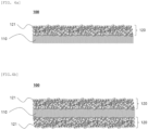
- FIGS. 1 and 4 are schematic views illustrating cross sections of a separator according to embodiments of the present disclosure.
- the separator 100 according to one embodiment of the present disclosure includes a separator substrate 110 and organic-inorganic composite porous coating layer 120 formed on one surface of the separator substrate 110.
- the separator substrate electrically isolates an anode and a cathode from each other.
- the separator provides a lithium pathway while preventing short-circuiting between the anode and the cathode.
- Any substrate can be used without limitation if it does not interfere with the function of the separator of an electrochemical device.
- a porous polymer film or nonwoven fabric including one or more selected from among polyolefins, polyethyleneterephthalates, polybutyleneterephthalates, polyacetals, polyamides, polycarbonates, polyimides, polyetheretherketones, polyethersulfones, polyphenylene oxides, polyphenylenesulfides, and polyethylenaphthalenesulfides may be used as the separator substrate.
- the thickness of the separator substrate may fall in the range of 3 um to 50 ⁇ m, preferably 10 um to 40 ⁇ m, more preferably 20 ⁇ m to 30 um.
- the thickness of the separator substrate is not limited to the range described above, when the thickness of the separator substrate is thinner than the lower limit of the above range, the mechanical properties of the separator substrate may deteriorate such that a separator including the separator substrate may be easily damaged during the use of the battery cell.
- the pore size and porosity of the separator substrate are also not particularly limited.
- the pore size and porosity of the separator substrate may fall within the range of 0.01 um to 50 ⁇ m, preferably 10 ⁇ m to 40 ⁇ m, more preferably 20 um to 30 um, and the range of 10 vol% to 95 vol%, preferably 25 vol% to 75 vol%, more preferably 40 vol% to 50 vol% respectively.
- the organic-inorganic composite porous coating layer may include a mixture of a plurality of inorganic particles and a binder. Since the separator substrate is covered by a coating layer including inorganic particles, the thermal resistance and mechanical properties of the separator can be improved. According to one preferred embodiment of the present disclosure as shown in FIG. 4b , each of the principal surfaces of the separator substrate is provided with the organic-inorganic composite porous coating layer. Since each of the principal surfaces of the separator is provided with the organic-inorganic composite porous coating layer, wet and dry adhesion can be improved between the anode and the separator and between the cathode and the separator.
- the amount of the polymer resin particles relative to 100 wt% of the porous coating layer may fall within the range of 1 wt% to 30 wt%.
- the amount of the polymer resin within the above range, reducing the heat resistance of the coating film and lowering the adhesive strength of the porous coating layer may be prevented.
- the organic-inorganic composite porous coating layer has a porous structure due to an interstitial volume between inorganic particles and binder including polymer resin particles.
- the interstitial volume also serves as a spacer to enable the physical shape of the coating layer to be maintained.
- the interstitial volume refers to a space in which the inorganic particles and the binder polymer resin particles are substantially confined while being in surface contact with each other.
- the separator since the inorganic particles generally are not likely to change in physical properties even at temperatures above 200°C, the separator has good thermal resistance due to the presence of the organic-inorganic composite porous coating layer.
- the organic-inorganic composite porous coating layer on an either-side surface of the separator may have a thickness in the range of 1 ⁇ m to 50 ⁇ m, preferably the range of 2 ⁇ m to 30 ⁇ m, or more preferably the range of 2 ⁇ m to 20 ⁇ m.
- the binder includes polymer resin particles.
- the polymer resin particles are present in a percentage in the range of 90 wt% to 99 wt%, more preferably 92 wt% to 96 wt%.
- the polymer resin particles may also be referred to as polymer particles or binder particles.
- the binder particles interconnect and coalesce the inorganic particles to form a porous coating layer having a layered structure. Referring to FIG. 1 , it is shown that the organic-inorganic composite porous coating layer is on a surface of the separator substrate, and the coating layer includes the inorganic particles and binder particles.
- each binder particle may include a PVDF-containing polymer and an acrylic polymer.
- the PVDF-containing polymer is present in the binder particle in an amount the range of 50 wt% to 80 wt% relative to 100 wt% of the blend, preferably 60 wt% to 75 wt% relative to 100 wt% of the blend, more preferably 65 wt% to 70 wt% relative to 100 wt% of the blend.
- the acrylic polymer is present in an amount in the range of 20 wt% to 50 wt% relative to 100 wt% of the blend, preferably 30 wt% to 45 wt% relative to 100 wt% of the blend, more preferably 35 wt% to 40 wt% relative to 100 wt% of the blend.
- both the dry adhesion and the wet adhesion of the separator can be improved.
- the particle size range of the binder particles may be the same as the particle size range of the inorganic particles.
- the PVDF-containing polymer may have a melting point in the range of 80°C to 200°C, preferably 100°C to 150°C, and exhibit high oxidation resistance in the electrolyte.
- the PVDF-containing polymer preferably has a Hansen Solubility parameter (HSP) value at 25 °C of 13 or less.
- the PVDF-containing based polymer preferably has a Hansen Solubility parameter (HSP) value at 25 °C of 13 or less.
- the PVDF-containing based polymer has a Hansen Solubility parameter (HSP) value at 25 °C of 1 or more and 13 or less, 2 or more and 12 or less, 3 or more and 11 or less, 4 or more and 10 or less, 5 or more and 9 or less, and 6 or more and 8 or less.
- the acrylic binder used in general has high reactivity with the electrolyte and swells in the electrolyte even though it has a cross-linked structure, it is difficult to achieve good wet adhesion because the binder sinks under the inorganic material after the separator is impregnated with the electrolyte as shown in FIG. 3b when the acrylic binder is used alone.
- PVDF-containing polymers having an HSP value of 13 or less and 1 or more are advantageous in maintaining the particle phase even in the electrolyte because such polymers have a significant difference in HSP value.
- the organic-inorganic composite porous coating layer according to the present disclosure is configured such that the amount of the binder resin is 50 wt% or higher relative to 100 wt% of the organic-inorganic composition porous coating layer, in a surface portion ranging from the outermost surface of the coating layer to a depth corresponding to 10% or less, or 9% or less, or 8% or less, or 7% or less, or 6% or less, or 3% or less of the thickness of the coating layer.
- the amount of the binder resin in the surface region portion is 55 wt% or higher, 60 wt% or higher, 65 wt% or higher, 70 wt% or higher, 75 wt% or higher, 80 wt% or higher, 85 wt% or higher, 90 wt% or higher, or 95 wt% or higher relative to 100 wt% of the organic-inorganic composition porous coating layer.
- the above-described surface portion will be referred to as an adhesive surface portion of the organic-inorganic composite porous coating layer.
- FIG. 4 is a schematic view illustrating a cross section of the separator 100 with the adhesive surface portion 121.
- the adhesive surface portion is a portion of the porous coating layer 120 and is inseparably combined with the porous coating layer. That is, the adhesive surface portion, even if shown for purposes of illustration, is not physically distinct from the porous coating layer. Stated differently the adhesive surface portion is not a separate layer, but rather a contiguous portion of the porous coating layer.
- the adhesive surface portion is used to clearly show a constructive feature in which the binder does not sink and is present in a high amount to be blended with the inorganic particles.
- the term "outermost surface” refers to a surface that comes into contact with an electrode when the separator is assembled with electrodes, and the term “downward” refers to a direction toward the separator substrate.
- reference numeral 110 denotes the separator substrate.
- HSP Hansen solubility parameter
- HSP is a vector having magnitude and direction in a space defined by three parameters, and ⁇ Tot represents the magnitude of the HSP vector.
- the basic unit representing HSP is (J/cm 3 )1 ⁇ 2.
- HSP values can be calculated using a program called Hansen Solubility Parameters in Practice (HSPiP) developed by the Dr. Hansen and his group, which proposed the HSP.
- HSP value may refer to a value at 25°C that is calculated for a desired material selected in the HSPiP program (5.0.04 version) after determining the structural formula of the material to be measured.
- the structural formula of the above polymer may be derived by assuming that the content of the repeating unit A and the content of the repeating unit B are regularly repeated.
- the PVDF-containing polymer is a polymer including vinylidene fluoride as the polymerization units.
- the PVDF-containing polymer may include a homopolymer of vinylidene fluoride (i.e., polyvinylidene fluoride), a copolymer of vinylidene fluoride and a polymerizable monomer (co-monomer), or a mixture of two or more of the homopolymer and the copolymer.
- the PVDF containing polymer includes, as a polymerization unit, a copolymer of vinylidene fluoride and a co-monomer.
- the co-monomer is contained in an amount in the range of 1 wt% to 20 wt%, or in the range of 5 wt% to 15 wt% with respect to 100 wt% of the PVDF-containing polymer.
- the amount of the co-monomer may be a substitution degree of the PVDF containing polymer.
- the amount of the co-monomer in the PVDF-containing polymer can be measured by 1 H-NMR using a Varian 500 MHz instrument.
- a Varian 500 MHz instrument For the details of the measurement method, Journal of Materials Chemistry, 2012, 22, 341 or AMT-3412-0k may be referred.
- appropriate equipment such as Bruker Avance III HD 700Mhz NMR or Varian 500MHz NMR, may be used.
- the co-monomer may be one or more selected from the group consisting of tetrafluoroethylene, hexafluoropropylene, trifluoroethylene, chlorofluoroethylene, 1,2 difluoroethylene, perfluoro(methylvinyl)ether, perfluoro(ethylvinyl)ether, perfluoro(propylvinyl)ether, durfluoro(1,3 dioxole), perfluoro(2,2-dimethyl-1,3-dioxole), trichloroethylene, and vinylfluoride.
- Non-limiting examples of the PVDF-based polymer include polyvinylidene fluoride, polyvinylidene fluoride-cohexafluoropropylene, polyvinylidene fluoride-cotrichloroethylene, polyvinylidene fluoride-cotetrafluoroethylene, and polyvinylidene fluoride-cotrifluoroethylene. Any one substance selected from the example may be used alone. Alternatively, a mixture of two or more substances selected from the examples may be used.
- the PVDF-containing polymer exhibits good adhesion in a dry state and has excellent oxidation resistance, thereby contributing to the adhesion of inorganic particles or maintaining the adhesion between the separator and the electrodes.
- the acrylic polymer has a glass transition temperature of 40°C or lower.
- the acrylic polymer is a polymer in which a carboxylic acid ester is a repeating unit.
- the acrylic polymer is a (meth)acrylic acid ester.
- (meth)acrylic acid ester examples include (meth)acrylic acid methyl, (meth)acrylic acid ethyl, (meth)acrylic acid n-propyl, (meth)acrylic acid i-propyl, (meth)acrylic acid n-butyl, (meth)acrylic acid i-butyl, (meth)acrylic acid n-amyl, (meth)acrylic acid i-amyl, (meth)acrylic acid hexyl, (meth)acrylic acid cyclohexyl, (meth)acrylic acid 2-ethylhexyl, (meth)acrylic acid n-octyl, (meth)acrylic acid nonyl, (meth)acrylic acid decyl, (meth)acrylic acid hydroxymethyl, (meth)acrylic acid hydroxyethyl, (meth)acrylic acid ethylene glycol, di(meth)acrylic acid ethylene glycol, di(
- One or more compounds selected from the examples of the (meth) acrylic acid ester may be used. Of these, one or more compounds selected from (meth)acrylic acid methyl, (meth)acrylic acid ethyl, and (meth)acrylic acid2-ethylhexyl are preferably used. More specifically, (meth) acrylic acid methyl is preferably used.
- the acrylic polymer may have constituent units derived from copolymerizable unsaturated monomers as well as repeating units derived from unsaturated carboxylic acid esters.
- the acrylic polymer has good flexibility and adhesion. However, since the acrylic polymer is not resistant to oxidation, when the acrylic polymer is used alone, the acrylic polymer oxidizes and degrades by repeated charging and discharging operations. Therefore, it is difficult to obtain good charging and discharging characteristics.
- the polymer particles including the PVDF-containing polymer and the acrylic polymer are used as a binder, and it is possible to secure both dry adhesion and wet adhesion when a separator and electrodes are combined.
- the separator may have a dry adhesion with an electrode of 10 gf/25mm or more and a wet adhesion with an electrode of 3 gf/20mm or more.
- the electrode may be a cathode, an anode, or both.
- the electrodes are not particularly limited when they can be used as an anode or a cathode for a lithium ion secondary battery.
- the adhesion may be measured using UTM equipment.
- the dry adhesion refers to an adhesive strength when the electrode and the separator are pressed against each other at 60°C at a pressure of 6.5 MPa for one second and then separated from each other at an angle of 180° at a rate of 300 mm/min.
- the wet adhesion refers to an adhesive strength measured when the electrodes and the separator are stacked and packaged into a pouch, an electrolyte is introduced into the pouch, and the stack of the electrodes and the separator is pressed at 70°C at a pressure of 5 kgf for 5 minutes, and then the electrodes and the separator are separated at an angle of 90° at a rate of 300 mm/min.
- the inorganic particles are not particularly limited if they are electrochemically stable. That is, the inorganic particles are not particularly limited if they are not oxidized and/or reduced in the operating voltage range (for example, 0 V to 5 V based on Li/Li+) of the electrochemical device.
- the ionic conductivity of the electrochemical device can be increased, resulting in improvement in performance.
- the ionic conductivity of the electrolyte may be improved because the inorganic particles contribute to an increase in the degree of dissociation of an electrolyte salt, such as a lithium salt, in a liquid electrolyte.
- the inorganic particles may include inorganic particles having a high dielectric constant of 5 or more or 10 or more, inorganic particles having the ability to transfer lithium ions, or a mixture thereof.
- the inorganic particles having a dielectric constant of 5 or more include BaTiO 3 , Pb (Zr, Ti) O 3 (PZT), Pb 1-x La x Zr 1-y Ti y O 3 (PLZT, where 0 ⁇ x ⁇ 1 and 0 ⁇ y ⁇ 1), Pb (Mg 1/3 Nb 2/3 ) O 3 -PbTiO 3 (PMN-PT), Hafnia (HfO 2 ), SrTiO 3 , SnO 2 , CeO 2 , MgO, NiO, CaO, ZnO, ZrO 2 , Y 2 O 3 , Al 2 O 3 , SiC, TiO 2 , and the like.
- any one of these materials may be used alone, or two or more materials of these materials may be used in combination.
- the synergistic effect can be obtained when the highdielectric inorganic particles and the inorganic particles having the ability to transfer lithium ions are used in combination.
- Non-limiting examples of the inorganic particles having the ability to transfer lithium ions include: (LiAlTiP) x O y -containing glass (x ⁇ 4, 0 ⁇ y ⁇ 13) such as lithium phosphate (Li 3 PO 4 ), lithium titanium phosphate (Li x Ti y (PO 4 ) 3 , 0 ⁇ x ⁇ y ⁇ 3), lithium aluminum titanium phosphate (Li x Al y Ti z (PO 4 ) 3 , 0 ⁇ x ⁇ 2, 0 ⁇ y ⁇ z ⁇ 3), and 14Li 2 O-9Al 2 O 3 -38TiO 2 -39P 2 O 5 , etc.; lithium germanium thiophosphate (Li x Ge y P z S w , 0 ⁇ x ⁇ 4, 0 ⁇ y ⁇ 1, 0 ⁇ z ⁇ 1, 0 ⁇ w ⁇ 5) such as Li 3.35 Ge 0.35 P 0.75 S 4 , etc.; lithium nitride (Li x N y , 0 ⁇ x ⁇ y ⁇ 2)
- P 2 S 5 -containing glass Li x P y S z , 0 ⁇ x ⁇ 3, 0 ⁇ y ⁇ 3, 0 ⁇ z ⁇ 7) such as LiI-Li 2 S-P 2 S 5 , etc.; and mixtures thereof.
- the amount of the inorganic particles is determined depending on the thickness, pore size, and porosity of the formed organic-inorganic composite porous coating layer.
- the amount of the inorganic particles relative to 100 wt% of the porous coating layer may fall within the range of 70 wt% to 99 wt%.
- the heat resistance of the coating film may be reduced.
- the amount of the inorganic particles is excessively high, the adhesive strength of the porous coating layer may be weak because the amount of the binder is insufficient.
- the size of the inorganic particles in the organic-inorganic composite porous coating layer is not particularly limited.
- the size of the inorganic particles in the organic-inorganic composite porous coating layer may be in the range of 0.001 ⁇ m to 10 ⁇ m, preferably 0.1 ⁇ m to 10 ⁇ m, more preferably from 1 um to 10 ⁇ m, for the formation of a coating layer with uniform thickness and appropriate porosity.
- the size may be in the range of 200 nm to 3 ⁇ m, the range of 200 nm to 2 ⁇ m, or the range of 200 nm to 1 ⁇ m.
- the size of the inorganic particles satisfies the mentioned range, it is easy to adjust the physical properties of the separator because the dispersion is maintained. In addition, it is possible to prevent the thickness of the organic-inorganic composite porous coating layer from increasing, the mechanical properties of the coating layer may be improved. In addition, there is a low probability that an internal shortcircuit occurs due to an excessively large pore size when the battery is charged or discharged.
- the pore size and porosity of the organic-inorganic composite porous coating layer depend primarily on the size of the inorganic particles. For example, when the inorganic particles having a particle size of 1 ⁇ m or less are used, the pores formed have a size of 1 ⁇ m or less. The pores are filled with an electrolyte that is subsequently introduced, and the electrolyte in the pores function as an ion pathway. Therefore, the pore size and porosity are principal factors determining the ionic conductivity of the organic-inorganic composite porous coating layer.
- the pore size and porosity of the organic-inorganic composite porous coating layer according to the present disclosure are preferably in the range of 0.001 ⁇ m to 10 ⁇ m, preferably 0.1 ⁇ m to 10 ⁇ m, more preferably from 1 ⁇ m to 10 ⁇ m, and the range of 5 vol% to 95 vol%, preferably 10 vol% to 80 vol%, more preferably 20 vol% to 70 vol%, respectively.
- a separator including the organic-inorganic composite porous coating layer may be manufactured by mixing binder particles and inorganic particles with a water-based solvent to prepare a coating slurry and applying the coating slurry on at least one surface of a separator substrate.
- dip coating, die coating, roll coating, comma coating, or a combination thereof may be used as a coating method.
- the water-based solvent may include one or more selected from water and C 1 -C 5 alcohols.
- the water-based solvent may include a mixture of water and isopropyl alcohol. Since the water-based solvent is used, the binder particles do not dissolve but remain as particles in the water-based solvent. That is, the binder particles are dispersed in the water-based solvent. For this reason, the binder particles can be maintained as the particle phase in the prepared organic-inorganic composite porous coating layer. Thus, it is prevented that the binder particles enter the pores of the separator substrate or sink to the bottom of the porous coating layer.
- the coating slurry has a solid content (not including the solvent) of 20 wt% to 50 wt%.
- the porous coating layer of the separator according to the present disclosure is characterized in that the binder does not sink to the bottom but is present at a high content in a superficial region of the coating layer. This may be attributable to the inclusion of a PVDF-containing polymer having an HSP value of 13 or less and 1 or more in the binder particles as described above. This effect may be further enhanced when the concentration of solids in the slurry is controlled to be within the range described above.
- the separator may be applied to an electrochemical device.
- the electrochemical device may include a cathode and an anode, and the separator may be provided between the cathode and the anode.
- Examples of the electrochemical device include all devices that perform electrochemical reactions. Specifically, for example, all kinds of primary cells, secondary cells, fuel cells, solar cells, and capacitors fall within the category of the electrochemical device.
- the electrochemical devices may be lithium ion secondary batteries including lithium metal secondary cells, lithium ion secondary cells, lithium polymer secondary cells, and lithium ion polymer secondary cells among the secondary cells.
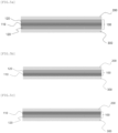
- FIG. 5a is a schematic diagram showing an electrochemical device including a separator 100 in which an organic/inorganic composite porous coating layer 120 is disposed on both sides of a separator substrate 110.
- the organic/inorganic composite porous coating layer 120 may be provided on each of the anode 200 and the cathode 300.
- FIG. 5b is a schematic diagram showing an electrochemical device including a separator 100 in which an organic/inorganic composite porous coating layer 120 is disposed on one surface of the separator substrate 110 adjacent to the anode 200.
- a separator in which an organic/inorganic composite porous coating layer 120 is disposed on one surface of the separator substrate 110 may be used, and the coating layer 120 may be disposed on the anode 200.
- FIG. 5c schematically shows an electrochemical device including a separator 100 in which an organic/inorganic composite porous coating layer 120 is disposed on one surface of the separator substrate 110 adjacent to the cathode 300.
- the separator 100 in which the organic/inorganic composite porous coating layer 120 is disposed on one surface of the separator substrate 110 is used, and the organic/inorganic composite porous coating layer 120 may be disposed on the cathode 300.
- the electrochemical device in the electrochemical device, includes an anode and a cathode, and an electrolyte solution may be included between the anode and the cathode, and the Hansen solubility factor of the electrolyte may be greater than by 8 or more than the Hansen solubility factor of the PVDF-based polymer.
- the Hansen solubility factor of the electrolyte solution can be greater than by 8 or more and 21 or less, by 9 or more and 20 or less, by 10 or more and 19 or less, by 11 or more and 18 or less, by 12 or more and 17 or less, by 13 or more and 16 or less, or by 14 or more and 15 or less, than the Hansen solubility factor of the PVDF-based polymer.
- the Hansen solubility factor of the electrolyte may mean a Hansen solubility factor of an organic solvent included in the electrolyte.
- the PVDF-based polymer is placed in one particle with the acrylic binder so that the acrylic binder does not sink under the inorganic material even under the electrolyte and thereby wet adhesion can be realized.
- the Hansen solubility factor of the electrolyte contained in the electrochemical device may be 14 or more and 35 or less.
- the Hansen solubility factor of the electrolyte contained in the electrochemical device is 15 or more and 34 or less, 16 or more and 33 or less, 17 or more and 32 or less, 18 or more and 31 or less, 19 or more and 30 or less , 20 or more and 29 or less, 21 or more and 28 or less, or 21 or more and 27 or less. More specifically, the Hansen solubility factor of the electrolyte included in the electrochemical device may be 21 or more and 22 or less.
- the acrylic binder contained in one particulate binder resin has a high affinity to the electrolyte and swells under the electrolyte even though it is crosslinked. After the electrolyte impregnation, the binder migrates to the bottom of the inorganic material, thereby preventing the deterioration of wet adhesion.
- the electrochemical devices may be manufactured according to conventional methods known in the art. According to one embodiment of the present disclosure, there is provided a method of forming the separator described above to be disposed between the anode and the cathode. In addition, an electrode assembly in which the anode, the separator, and the cathode are stacked is introduced into a battery case, and then an electrolyte liquid is charged into the battery case to produce the electrochemical device.
- the electrode is not particularly limited, and the electrode can be manufactured in the form in which an electrode active material is bonded to a current collector by a known method in the art.
- the cathodic active material of the electrode active materials are conventional cathodic active materials that can be used in cathodes of conventional electrochemical devices.
- lithium intercalation materials such as lithium manganese oxide, lithium cobalt oxide, lithium nickel oxide, lithium iron oxide, and combinations thereof may be used.
- Non-limiting examples of the anodic active material are conventional anodic active materials that can be used in anodes of conventional electrochemical devices.
- lithium intercalation materials such as lithium metal, lithium alloy, carbon, petroleum coke, activated carbon, graphite, and other carbides are preferably used.
- Non-limiting examples of the cathodic current collector include foils made of aluminum, nickel, or a combination thereof.
- Non-limiting examples of the anodic current collector include foils made of copper, gold, nickel, or a combination thereof.
- the electrolyte liquid that can be used in the present disclosure is a liquid in which a salt with a structure of A + B - is dissolved or dissociated in an organic solvent, in which: A + includes alkali metal cations such as Li + , Na + , K + or a combination thereof; B - includes anions such as PF 6 - , BF 4 - , Cl - , Br - , I - , ClO 4 - , AsF 6 - , CH 3 CO 2 - , CF 3 SO 3 - , NCF 3 (SO 2 ) 2 - , CCF 2 (SO 2 ) 3 - or a combination thereof; and the organic solvent includes propylene carbonate (PC), ethylene carbonate (EC), diethylcarbonate (DEC), dimethylcarbonate (DMC), dipropylcarbonate (DPC), dimethylsulfoxide, acetonitrile, dimethoxyethane, diethoxyethane, te
- the salt and the organic solvent are not limited thereto.
- the organic solvent may be a mixture of ethylene carbonate (EC) and dimethylcarbonate (DMC) with a weight ratio of 1:9 to 9:1.
- the electrolyte injection may be performed at an appropriate stage during the cell manufacturing process, depending on the manufacturing method and the required physical properties of the final product. That is, the electrolyte injection may be performed before cell assembling or at the final stage of cell assembling.
- the cell assembling using an electrode assembly involves winding, lamination or stack of a separator and electrodes, and folding.
- a dispersion (having a solid content of 30%) for forming a porous coating layer was prepared by dispersing polymer resin particles as a binder having a particle size of 500 nm and inorganic particles (Al 2 O 3 ) having a particle size of 500 nm into water. The amount ratio (on a weight basis) of the binder particles and the inorganic particles was 10:90.
- a separator substrate which is made of polyethylene and that has a porosity of 40% and a thickness of 9 um was prepared. The dispersion was applied to a surface of the separator substrate through a bar-coating method using a doctor blade. The applied dispersion was dried with a heat gun at a temperature of 50°C.
- the binder particles are blended particles in which a PVDF-containing polymer and an acrylic polymer are mixed in a weight ratio of 70:30.
- the PVDF-containing polymer was PVDF-HFP and had a HFP substitution degree (i.e., the amount of HFP including in the PVDF containing polymer) of 5 wt% and an HSP value of 12.
- the acrylic polymer was styrene-butyl acrylate.
- a separator was manufactured in the same manner as in Example 1, except that the PVDF-containing polymer used for the particle-phase binder in Example 1 was changed to a PVDF-containing polymer having an HFP substitution degree of 15 wt% and a HSP value of 13.
- a separator was manufactured in the same manner as in Example 1, except that the particle-phase binder particles are blended particles in which a PVDF containing polymer and an acrylic polymer are mixed in a weight ratio of 50:50.
- a dispersion (having a solid content of 30%) for forming a porous coating layer was prepared by dispersing a particle-phase binder (styrene-butylacrylate) having a particle size of 500 nm and inorganic particles (Al 2 O 3 ) having a particle size of 500 nm into water. The amount ratio (on a weight basis) of the binder and the inorganic particles was 15:85.
- a separator substrate which is made of polyethylene and that has a porosity of 40% and a thickness of 9 um was prepared. The dispersion was applied to a surface of the separator substrate through a bar-coating method using a doctor blade. The applied dispersion was dried with a heat gun at a temperature of 50°C.
- the HSP of the particle-phase binder was 17.
- a separator was manufactured in the same manner as in Example 1, except that the PVDF-containing polymer used for the particle-phase binder in Example 1 was changed to a PVDF-containing polymer having a HFP substitution degree of 22 wt% and a HSP value of 14.
- a separator was manufactured in the same manner as in Comparative Example 1, except that the particle-phase binder particles are blended particles in which a PVDF containing polymer and an acrylic polymer are mixed in a weight ratio of 30:70.
- a separator was manufactured in the same manner as in Comparative Example 1, except that the particle-phase binder particles are blended particles in which a PVDF containing polymer and an acrylic polymer are mixed in a weight ratio of 85:15.
- a dispersion (having a solid content of 30 wt%) for forming a porous coating layer was prepared by dispersing polymer resin particles as a binder having a particle size of 500 nm and inorganic particles (Al 2 O 3 ) having a particle size of 500 nm into water. The amount ratio (on a weight basis) of the binder particles and the inorganic particles was 10:90.
- a separator substrate which is made of polyethylene and that has a porosity of 40% and a thickness of 9 um was prepared.
- the dispersion was applied to a surface of the separator substrate through a bar-coating method using a doctor blade.
- the applied dispersion was dried with a heat gun at a temperature of 50°C.
- the binder particles were a PVDF containing polymer which was PVDF-HFP and had a HFP substitution degree (the amount of HFP included in the PVDF containing polymer) of 5 wt% and an HSP value of 12.
- the resulting structure was left at room temperature for 24 hours.
- Lamination was performed with a hot press to prepare specimens. In this case, the pressing was carried out at 70°C and 5 kgf for 5 minutes.
- the specimens had a size of 2 cm x 6 cm.
- the cathode was prepared according to a method described below. LiNi 0.8 Co 0.1 Mn 0.1 O 2 , PVDF, and carbon black were mixed at a weight ratio of 97.0:1.5:1.5 and dispersed in 2-methyl-2-pyrrolidone to prepare a cathode slurry, and the cathode slurry was applied onto an aluminum current collector, dried, and rolled to produce the cathode.
- each of the separators prepared in the examples and comparative examples and an anode were stacked, and the stack was laminated with a hot press to produce specimens.
- the pressing was carried out at 60°C and 6.5 MPa for 1 minute.
- the specimens had a size of 2.5 cm x 6 cm.
- the anode was prepared according to a method described below. Graphite, SBR, and CMC were mixed at a weight ratio of 89.2:10:0.8 and dispersed in distilled water to prepare an anode slurry. The anode slurry was applied onto a copper current collector, dried, and rolled to prepare the anode.
- the wet adhesion and dry adhesion of the separators prepared as above were evaluated using each of the specimens prepared above, and the results are summarized in Table 1.
- the specimens were left at room temperature for 1 hour after the preparation, and the adhesion was measured.
- the dry adhesion and wet adhesion were measured using a tensile tester (UTM equipment) while peeling the separator at an angle of 180° and an angle of 90°, respectively.
- Example 1 Example 2 Example 3 Wet adhesion (gf/20 mm) 20 25 12 Dry adhesion (gf/25 mm) 40 45 30 Comparative Example 1 Comparative Example 2 Comparative Example 3 Comparative Example 4 Comparative Example 5 Wet adhesion (gf/20 mm) 0 2 2 8 0 Dry adhesion (gf/25 mm) 60 50 40 10 0
- the separators according to the present disclosure have high wet and dry adhesion to the electrodes compared to the separators of the Comparative Examples.
- the separators of the Comparative Examples 1 to 3 exhibit high dry adhesion and low wet adhesion.
- the separators of the Comparative Examples 4 and 5 exhibit low dry adhesion and low wet adhesion. Therefore, when these separators are applied to batteries, the performance of the batteries may be deteriorated.
- the separators according to the examples exhibit good dry adhesion and good wet adhesion, an excellent electrochemical effect can be achieved when manufacturing electrode assemblies and during the operation of batteries.
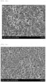
- FIGS. 2a and 2b are SEM images obtained before and after electrolyte impregnation, respectively, the SEM images showing the surface of a separator prepared according to Example 1.
- FIGS. 3a and 3b are SEM images obtained before and after electrolyte impregnation, respectively, the SEM images showing the surface of a separator prepared according to Comparative Example 1.
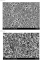
- FIGS. 6a and 6b are SEM images obtained before and after electrolyte impregnation, respectively, and the SEM images show the surface of a separator prepared according to Comparative Example 2.
- each of the separators i.e., surface of each of the organic-inorganic composite porous coating layers respectively prepared according to Example 1 and Comparative Examples land 2
- the inorganic particles and the binder maintain a particle phase, and the inter-particle interstitial volume is formed.
- the binder remained as the particle phase while maintaining the interstitial volume, similarly to the state in which the separator was not yet impregnated with the electrolyte.
- Comparative Examples 1 and 2 the particle phase of the binder collapsed. That is, it was difficult to identify the particles.
- the binder since the binder sank to the bottom of the porous coating layer, the amount of the binder on the surface of the separator was small, resulting in a problem of deterioration in wet adhesion.
Landscapes
- Chemical & Material Sciences (AREA)
- Chemical Kinetics & Catalysis (AREA)
- Electrochemistry (AREA)
- General Chemical & Material Sciences (AREA)
- Engineering & Computer Science (AREA)
- Power Engineering (AREA)
- Inorganic Chemistry (AREA)
- Composite Materials (AREA)
- Materials Engineering (AREA)
- Microelectronics & Electronic Packaging (AREA)
- Cell Separators (AREA)
- Electric Double-Layer Capacitors Or The Like (AREA)
- Secondary Cells (AREA)
Abstract
Description
- The present application claims priority to
Korean Patent Application No. 10-2021-0147362, filed October 29, 2021 - The present disclosure relates to an electrochemical device separator having improved dry adhesion and wet adhesion.
- A secondary battery includes a cathode, an anode, a separator, and an electrolyte which are key components. Such a secondary battery is a high-density energy storage device that is charged and discharged by reversible conversion between chemical energy and electrical energy and has various applications such as small electronic equipment including mobile phones, laptop computers, etc. Recently, applications have rapidly expanded to hybrid electric vehicles (HEVs), plug-in electric vehicles (Plug-in EVs), electric bicycles (e-bikes), and energy storage systems (ESS) to deal with environmental issues, high oil price, high energy efficiency, and energy storage with high energy density.
- In manufacturing and using secondary batteries, ensuring safety thereof is an important challenge. Particularly, separators commonly used in electrochemical devices exhibit extreme thermal shrinkage behavior in high-temperature conditions due to their material properties and process characteristics when manufactured, thereby having safety issues. To ensure the safety of secondary batteries, an organic-inorganic composite porous separator having an organic-inorganic composite porous coating layer has been proposed (refer to
Korean Patent Application No. 10-2004-0070096 - An objective of the present disclosure is to provide a separator having excellent adhesion with an electrode both in a dry state and a wet state. Another objective of the present disclosure is to provide a separator in which inorganic particles are not dislodged from an organic-inorganic composite porous coating layer and which maintains high durability and insulation. Other objectives and advantages of the present disclosure will be appreciated by a description given below. It will be readily apparent that the objectives and advantages of the present disclosure can be achieved by means or methods and combinations thereof recited in the claims.
- A first aspect of the present disclosure relates to a separator for an electrochemical device, the separator including a separator substrate and an organic-inorganic composite porous coating layer on at least one surface of the separator substrate. The separator substrate is a porous film including a polyolefin-containing polymer. The organic-inorganic composite porous coating layer includes polymer resin particles and inorganic particles. In the polymer resin particles, each particle includes a polyvinylidene fluoridecontaining polymer (PVDF-containing polymer) and an acrylic polymer. The PVDF-containing polymer has a Hansen solubility parameter (HSP) value of 13 or less.
- A second aspect of the present disclosure is that in the first aspect described above, the PVDF-containing polymer includes a homopolymer of vinylidene fluoride (for example, polyvinylidene fluoride), a copolymer of vinylidene fluoride and another polymerizable monomer (co-monomer), or a mixture of two or more of the homopolymers and copolymers. The co-monomer includes one or more substances selected from the group consisting of tetrafluoroethylene, hexafluoropropylene, trifluoroethylene, chlorofluoroethylene, 1,2 difluoroethylene, perfluoro(methylvinyl)ether, perfluoro(ethylvinyl)ether, perfluoro (propylvinyl)ether, durfluoro(1,3 dioxole), perfluoro(2,2-dimethyl-1,3-dioxole), trichloroethylene, and vinyl fluoride.
- A third aspect of the present disclosure is that in the second aspect described above, the PVDF-containing polymer includes a copolymer of vinylidene fluoride and the co-monomer as a polymerization unit, in which the content of the co-monomer falls within a range of 1 wt% to 20wt % with respect to 100 wt% of the PVDF-containing polymer.
- A fourth aspect of embodiment of the present disclosure is that, in any of the first to third aspects described above, PVDF-containing polymer has a melting point (Tm) in the range of 80°C to 200°C.
- A fifth aspect of the present disclosure is that in any of the first to fourth aspects described above, the acrylic polymer is a polymer having carboxylic acid esters as repeating units.
- A sixth aspect of the present disclosure is that in the fifth aspect described above, acrylic polymer has a glass transition temperature (Tg) of 40°C or lower.
- A seventh aspect of the present disclosure is that in any of the first to fifth aspects described above, the inorganic particles have an particle size in the range of 200 nm to 3 um.
- An eighth of the present disclosure is that in any of the first to seventh aspects described above, the amount of the particle-phase binder resin in the organic-inorganic composite porous coating layer falls within the range of 1 wt% to 30 wt% with respect to 100 wt% of the organic-inorganic composite porous coating layer.
- A ninth of the present disclosure is that in any of the first to eight aspects described above, the organic-inorganic composite porous coating layer has a porous structure in which a mixture of inorganic particles and binder resin particles are connected and integrated into a layered structure which is porous due to the interstitial volume formed between the inorganic and the binder resin particles.
- A tenth aspect of the present disclosure is that in any of the first to ninth aspects described above, the inorganic particles do not undergo oxidation and/or reduction at a voltage level in a range of 0 V to 5 V (Li/Li+), which is an operating voltage range of an electrochemical device.
- An eleventh aspect of the present disclosure is that the organic-inorganic composite porous coating layer is present on the separator for an electrochemical device in the first aspect described above, and includes an adhesive surface portion present from an outermost surface of the organic-inorganic composite porous coating layer to a thickness of 10% below with respect to a 100% thickness of the organic-inorganic composite porous coating layer, and a concentration of the polymer resin particles present in the adhesive surface portion is greater than a concentration of the inorganic particles present in the adhesive surface portion.
- A twelfth aspect of the present disclosure is that the organic-inorganic composite porous coating layer of the first aspect described above is present on both surfaces of the separator substrate, and each of the organic-inorganic composite porous coating layers includes an adhesive surface portion present from an outermost surface of each organic-inorganic composite porous coating layer to a thickness of 10% below with respect to a 100% thickness of the organic-inorganic composite porous coating layer, and a concentration of the polymer resin particles present in each adhesive surface portion is greater than a concentration of the inorganic particles present in each adhesive surface portion.
- A thirteenth aspect of the present disclosure relates to an electrochemical device, including an anode, a cathode, an electrolyte, and the separator, where the separator is interposed between the anode and the cathode, and where the adhesive surface portion is in direct contact with the anode, and/or with the cathode. In one embodiment, a Hansen solubility parameter (HSP) value of the electrolyte is 8 and more greater than that of the PVDF containing polymer.
- A fourteenth aspect of the present disclosure includes an anode, a cathode, a separator according to the eleventh aspect and the separator is interposed between the anode and the cathode, and the adhesive surface portion is in direct contact with the anode, and/or with the cathode.
- A fifteenth aspect of the present disclosure relates to an electrochemical device including an anode, a cathode, and the separator, where the separator is interposed between the anode and the cathode, and where one adhesive surface portion is in direct contact with the cathode, and the opposite adhesive surface portion is in contact with the anode.
- The separator according to the present disclosure is configured such that a particle-phase binder resin including a mixture of an acrylic binder and a PVDF-containing binder is present in an organic-inorganic composite porous coating layer. Therefore, the separator has excellent adhesion to an electrode both in a dry state and a wet state. Therefore, the form stability and the processability of an electrode assembly can be improved in a roll-to-roll continuous process in which electrodes and the separator are stacked to form an electrode assembly. In addition, when a cell is manufactured using an electrode assembly including the separator, and the separator is impregnated with an electrolyte, a high adhesive strength between the separator and the electrodes can be maintained, and thus the interfacial resistance property of the cell does not deteriorate. In addition, since the binder resin particles maintain high dry adhesion and high wet adhesion, the inorganic particles included in the organic-inorganic composite porous coating layer are not dislodged but remain stably fixed. Therefore, the form stability of the separator can be improved. For this reason, the thermal safety and electrical insulation of the cell are improved. In addition, since the porous coating layer has a porous structure due to the inter-particle interstitial volume, the porous coating layer does not interfere with ion conduction between the electrode and the separator. Therefore, the porous coating layer exhibits a minor increase in resistance and has a good lifespan.
- The accompanying drawings illustrate preferred embodiments of the present disclosure and illustrate the principles of the present disclosure in conjunction with a detailed description given below, but the scope of the present disclosure is not limited thereto. The shape, size, scale, or ratio of the elements illustrated in the drawings and described herein may be exaggerated to emphasize the clarity of each element.
-
FIG. 1 is a schematic view illustrating a cross section of a separator according to one embodiment of the present disclosure; -
FIGS. 2a and2b are SEM images obtained before and after electrolyte impregnation, respectively, and the SEM images show the surface of a separator prepared according to Example 1; -
FIGS. 3a and3b are SEM images obtained before and after electrolyte impregnation, respectively, and the SEM images show the surface of a separator prepared according to Comparative Example 1; and -
FIG. 4 are schematic diagrams illustrating cross-sections of a separator according to embodiments of the present disclosure, in which a portion having a relatively high amount of binder resin is formed on the surface of the separator. Specifically,FIG. 4a is a schematic diagram illustrating a separator comprising an organic-inorganic composite porous coating layer on one surface of a separator substrate, andFIG. 4b is a schematic diagram illustrating a separator comprising organic-inorganic composite porous coating layers on both surfaces of a separator substrate. -
FIG. 5 are schematic diagrams illustrating electrochemical devices according to embodiments of the present disclosure. Specifically,FIG. 5a is a schematic diagram illustrating an electrochemical device which comprises a separator with organic-inorganic composite porous coating layers on both surfaces of a separator substrate, andFIG. 5b is a schematic diagram illustrating an electrochemical device which comprises a separator with an organic-inorganic composite porous coating layer on a surface of the separator substrate which is adjacent to an anode, andFIG. 5c is a schematic diagram illustrating an electrochemical device which comprises a separator with an organic-inorganic composite porous coating layer on a surface of the separator substrate which is adjacent to a cathode. -
FIGS. 6a and 6b are SEM images obtained before and after electrolyte impregnation, respectively, and the SEM images show the surface of a separator prepared according to Comparative Example 2. - Prior to giving the following detailed description of the present disclosure, it should be noted that the terms and words used in the specification and the claims should not be construed as being limited to ordinary meanings or dictionary definitions but should be construed in a sense and concept consistent with the technical idea of the present disclosure, on the basis that the inventor can properly define the concept of a term to describe its invention in the best way possible. The exemplary embodiments described herein and the configurations illustrated in the drawings are presented for illustrative purposes and do not exhaustively represent the technical spirit of the present disclosure. Accordingly, it should be appreciated that there will be various equivalents and modifications that can replace the exemplary embodiments and the configurations at the time at which the present application is filed.
- The present disclosure relates to a separator for an electrochemical device. According to the present disclosure, the separator includes a porous separator substrate and an organic-inorganic composite porous coating layer on at least one surface of the separator substrate. The porous coating layer contains polymer resin particles as a binder, and the particles contain an acrylic polymer and a PVDF- containing polymer.
-
FIGS. 1 and4 are schematic views illustrating cross sections of a separator according to embodiments of the present disclosure. Referring toFIG. 4 , theseparator 100 according to one embodiment of the present disclosure includes aseparator substrate 110 and organic-inorganic compositeporous coating layer 120 formed on one surface of theseparator substrate 110. Hereinafter, exemplary embodiments of the present disclosure will be described in detail with reference to the accompanying drawings. - According to one embodiment of the present disclosure, the separator substrate electrically isolates an anode and a cathode from each other. The separator provides a lithium pathway while preventing short-circuiting between the anode and the cathode. Any substrate can be used without limitation if it does not interfere with the function of the separator of an electrochemical device. As such as a separator substrate, a porous polymer film or nonwoven fabric including one or more selected from among polyolefins, polyethyleneterephthalates, polybutyleneterephthalates, polyacetals, polyamides, polycarbonates, polyimides, polyetheretherketones, polyethersulfones, polyphenylene oxides, polyphenylenesulfides, and polyethylenaphthalenesulfides may be used as the separator substrate.
- In the present disclosure, the thickness of the separator substrate may fall in the range of 3 um to 50 µm, preferably 10 um to 40 µm, more preferably 20 µm to 30 um. Although the thickness of the separator substrate is not limited to the range described above, when the thickness of the separator substrate is thinner than the lower limit of the above range, the mechanical properties of the separator substrate may deteriorate such that a separator including the separator substrate may be easily damaged during the use of the battery cell. The pore size and porosity of the separator substrate are also not particularly limited. However, the pore size and porosity of the separator substrate may fall within the range of 0.01 um to 50 µm, preferably 10 µm to 40 µm, more preferably 20 um to 30 um, and the range of 10 vol% to 95 vol%, preferably 25 vol% to 75 vol%, more preferably 40 vol% to 50 vol% respectively.
- The organic-inorganic composite porous coating layer may include a mixture of a plurality of inorganic particles and a binder. Since the separator substrate is covered by a coating layer including inorganic particles, the thermal resistance and mechanical properties of the separator can be improved. According to one preferred embodiment of the present disclosure as shown in
FIG. 4b , each of the principal surfaces of the separator substrate is provided with the organic-inorganic composite porous coating layer. Since each of the principal surfaces of the separator is provided with the organic-inorganic composite porous coating layer, wet and dry adhesion can be improved between the anode and the separator and between the cathode and the separator. - According to an embodiment of the present disclosure, in the organic-inorganic composite porous coating layer, the amount of the polymer resin particles relative to 100 wt% of the porous coating layer may fall within the range of 1 wt% to 30 wt%. By adjusting the amount of the polymer resin within the above range, reducing the heat resistance of the coating film and lowering the adhesive strength of the porous coating layer may be prevented.
- The organic-inorganic composite porous coating layer has a porous structure due to an interstitial volume between inorganic particles and binder including polymer resin particles. In addition, the interstitial volume also serves as a spacer to enable the physical shape of the coating layer to be maintained. The interstitial volume refers to a space in which the inorganic particles and the binder polymer resin particles are substantially confined while being in surface contact with each other. In addition, since the inorganic particles generally are not likely to change in physical properties even at temperatures above 200°C, the separator has good thermal resistance due to the presence of the organic-inorganic composite porous coating layer. In the present disclosure, the organic-inorganic composite porous coating layer on an either-side surface of the separator may have a thickness in the range of 1 µm to 50 µm, preferably the range of 2 µm to 30 µm, or more preferably the range of 2 µm to 20 µm.
- In the present disclosure, the binder includes polymer resin particles. In one embodiment of the present disclosure, of 100 wt% of the binder, the polymer resin particles are present in a percentage in the range of 90 wt% to 99 wt%, more preferably 92 wt% to 96 wt%. The polymer resin particles may also be referred to as polymer particles or binder particles. The binder particles interconnect and coalesce the inorganic particles to form a porous coating layer having a layered structure. Referring to
FIG. 1 , it is shown that the organic-inorganic composite porous coating layer is on a surface of the separator substrate, and the coating layer includes the inorganic particles and binder particles. - According to one specific embodiment of the present disclosure, each binder particle may include a PVDF-containing polymer and an acrylic polymer. In one specific embodiment of the present disclosure, the PVDF-containing polymer is present in the binder particle in an amount the range of 50 wt% to 80 wt% relative to 100 wt% of the blend, preferably 60 wt% to 75 wt% relative to 100 wt% of the blend, more preferably 65 wt% to 70 wt% relative to 100 wt% of the blend.
- In addition, the acrylic polymer is present in an amount in the range of 20 wt% to 50 wt% relative to 100 wt% of the blend, preferably 30 wt% to 45 wt% relative to 100 wt% of the blend, more preferably 35 wt% to 40 wt% relative to 100 wt% of the blend.
- When the PVDF-containing polymer and the acrylic polymer satisfy the amount ranges described above, both the dry adhesion and the wet adhesion of the separator can be improved.
- In the present disclosure, the particle size range of the binder particles may be the same as the particle size range of the inorganic particles.
- In one specific embodiment of the present disclosure, the PVDF-containing polymer may have a melting point in the range of 80°C to 200°C, preferably 100°C to 150°C, and exhibit high oxidation resistance in the electrolyte.
- In one embodiment of the present disclosure, the PVDF-containing polymer preferably has a Hansen Solubility parameter (HSP) value at 25 °C of 13 or less. Specifically, the PVDF-containing based polymer preferably has a Hansen Solubility parameter (HSP) value at 25 °C of 13 or less. Preferably, the PVDF-containing based polymer has a Hansen Solubility parameter (HSP) value at 25 °C of 1 or more and 13 or less, 2 or more and 12 or less, 3 or more and 11 or less, 4 or more and 10 or less, 5 or more and 9 or less, and 6 or more and 8 or less. Since the acrylic binder used in general has high reactivity with the electrolyte and swells in the electrolyte even though it has a cross-linked structure, it is difficult to achieve good wet adhesion because the binder sinks under the inorganic material after the separator is impregnated with the electrolyte as shown in
FIG. 3b when the acrylic binder is used alone. PVDF-containing polymers having an HSP value of 13 or less and 1 or more are advantageous in maintaining the particle phase even in the electrolyte because such polymers have a significant difference in HSP value. Therefore, in the case where a PVDF-containing polymer having an HSP value of 13 or less and 1 or more and an acrylic polymer are included in one particle, wet adhesion is improved because the PVDF-containing polymer prevents the acrylic binder from sinking below the inorganic particles in the electrolyte. - In this aspect, the organic-inorganic composite porous coating layer according to the present disclosure is configured such that the amount of the binder resin is 50 wt% or higher relative to 100 wt% of the organic-inorganic composition porous coating layer, in a surface portion ranging from the outermost surface of the coating layer to a depth corresponding to 10% or less, or 9% or less, or 8% or less, or 7% or less, or 6% or less, or 3% or less of the thickness of the coating layer. Alternatively, the amount of the binder resin in the surface region portion is 55 wt% or higher, 60 wt% or higher, 65 wt% or higher, 70 wt% or higher, 75 wt% or higher, 80 wt% or higher, 85 wt% or higher, 90 wt% or higher, or 95 wt% or higher relative to 100 wt% of the organic-inorganic composition porous coating layer. For convenience of description, the above-described surface portion will be referred to as an adhesive surface portion of the organic-inorganic composite porous coating layer.
FIG. 4 is a schematic view illustrating a cross section of theseparator 100 with theadhesive surface portion 121. The adhesive surface portion is a portion of theporous coating layer 120 and is inseparably combined with the porous coating layer. That is, the adhesive surface portion, even if shown for purposes of illustration, is not physically distinct from the porous coating layer. Stated differently the adhesive surface portion is not a separate layer, but rather a contiguous portion of the porous coating layer. The adhesive surface portion is used to clearly show a constructive feature in which the binder does not sink and is present in a high amount to be blended with the inorganic particles. The term "outermost surface" refers to a surface that comes into contact with an electrode when the separator is assembled with electrodes, and the term "downward" refers to a direction toward the separator substrate. InFIG. 4 ,reference numeral 110 denotes the separator substrate. - The Hansen solubility parameter (HSP) was developed by Dr. Charles M. Hansen, and there are three parameters depending on the degree of binding in a substance:
- (1) Solubility parameter δD attributable to non-polar dispersion forces;
- (2) Solubility parameter δP attributable to dipolar intermolecular force; and
- (3) Solubility parameter δH attributable to hydrogen bonds.
- As such, with the HSP, it is possible to accurately and systematically assess the solubility or mixability of a substance by the following expressions:


- HSP is a vector having magnitude and direction in a space defined by three parameters, and δTot represents the magnitude of the HSP vector. The basic unit representing HSP is (J/cm3)½. These HSP values can be calculated using a program called Hansen Solubility Parameters in Practice (HSPiP) developed by the Dr. Hansen and his group, which proposed the HSP. Specifically, the HSP value may refer to a value at 25°C that is calculated for a desired material selected in the HSPiP program (5.0.04 version) after determining the structural formula of the material to be measured. The structural formula of the above polymer may be derived by assuming that the content of the repeating unit A and the content of the repeating unit B are regularly repeated.
- In one embodiment of the present disclosure, the PVDF-containing polymer is a polymer including vinylidene fluoride as the polymerization units. The PVDF-containing polymer may include a homopolymer of vinylidene fluoride (i.e., polyvinylidene fluoride), a copolymer of vinylidene fluoride and a polymerizable monomer (co-monomer), or a mixture of two or more of the homopolymer and the copolymer.
- Preferably, the PVDF containing polymer includes, as a polymerization unit, a copolymer of vinylidene fluoride and a co-monomer. Preferably, the co-monomer is contained in an amount in the range of 1 wt% to 20 wt%, or in the range of 5 wt% to 15 wt% with respect to 100 wt% of the PVDF-containing polymer. The amount of the co-monomer may be a substitution degree of the PVDF containing polymer.
- In the present disclosure, the amount of the co-monomer in the PVDF-containing polymer can be measured by 1H-NMR using a Varian 500 MHz instrument. For the details of the measurement method, Journal of Materials Chemistry, 2012, 22, 341 or AMT-3412-0k may be referred. For the identification of the NMR spectra, appropriate equipment, such as Bruker Avance III HD 700Mhz NMR or Varian 500MHz NMR, may be used.
- The co-monomer may be one or more selected from the group consisting of tetrafluoroethylene, hexafluoropropylene, trifluoroethylene, chlorofluoroethylene, 1,2 difluoroethylene, perfluoro(methylvinyl)ether, perfluoro(ethylvinyl)ether, perfluoro(propylvinyl)ether, durfluoro(1,3 dioxole), perfluoro(2,2-dimethyl-1,3-dioxole), trichloroethylene, and vinylfluoride. Non-limiting examples of the PVDF-based polymer include polyvinylidene fluoride, polyvinylidene fluoride-cohexafluoropropylene, polyvinylidene fluoride-cotrichloroethylene, polyvinylidene fluoride-cotetrafluoroethylene, and polyvinylidene fluoride-cotrifluoroethylene. Any one substance selected from the example may be used alone. Alternatively, a mixture of two or more substances selected from the examples may be used.
- The PVDF-containing polymer exhibits good adhesion in a dry state and has excellent oxidation resistance, thereby contributing to the adhesion of inorganic particles or maintaining the adhesion between the separator and the electrodes.
- The acrylic polymer has a glass transition temperature of 40°C or lower. The acrylic polymer is a polymer in which a carboxylic acid ester is a repeating unit. Preferably, the acrylic polymer is a (meth)acrylic acid ester. Specific examples of such a (meth)acrylic acid ester include (meth)acrylic acid methyl, (meth)acrylic acid ethyl, (meth)acrylic acid n-propyl, (meth)acrylic acid i-propyl, (meth)acrylic acid n-butyl, (meth)acrylic acid i-butyl, (meth)acrylic acid n-amyl, (meth)acrylic acid i-amyl, (meth)acrylic acid hexyl, (meth)acrylic acid cyclohexyl, (meth)acrylic acid 2-ethylhexyl, (meth)acrylic acid n-octyl, (meth)acrylic acid nonyl, (meth)acrylic acid decyl, (meth)acrylic acid hydroxymethyl, (meth)acrylic acid hydroxyethyl, (meth)acrylic acid ethylene glycol, di(meth)acrylic acid ethylene glycol, di(meth)acrylic acid propylene glycol, tri(meth)acrylic acid trimethylolpropane, tetra(meth)acrylic acid pentaerythritol, hexa(meth)acrylic acid dipentaerythritol, (meth)allyl acrylate, and di(meth)ethylene acrylate. One or more compounds selected from the examples of the (meth) acrylic acid ester may be used. Of these, one or more compounds selected from (meth)acrylic acid methyl, (meth)acrylic acid ethyl, and (meth)acrylic acid2-ethylhexyl are preferably used. More specifically, (meth) acrylic acid methyl is preferably used.
- In addition, the acrylic polymer may have constituent units derived from copolymerizable unsaturated monomers as well as repeating units derived from unsaturated carboxylic acid esters.
- The acrylic polymer has good flexibility and adhesion. However, since the acrylic polymer is not resistant to oxidation, when the acrylic polymer is used alone, the acrylic polymer oxidizes and degrades by repeated charging and discharging operations. Therefore, it is difficult to obtain good charging and discharging characteristics.
- According to the present disclosure, since the polymer particles including the PVDF-containing polymer and the acrylic polymer are used as a binder, and it is possible to secure both dry adhesion and wet adhesion when a separator and electrodes are combined.
- In one embodiment of the present disclosure, the separator may have a dry adhesion with an electrode of 10 gf/25mm or more and a wet adhesion with an electrode of 3 gf/20mm or more. The electrode may be a cathode, an anode, or both. The electrodes are not particularly limited when they can be used as an anode or a cathode for a lithium ion secondary battery. The adhesion may be measured using UTM equipment. Specifically, the dry adhesion refers to an adhesive strength when the electrode and the separator are pressed against each other at 60°C at a pressure of 6.5 MPa for one second and then separated from each other at an angle of 180° at a rate of 300 mm/min. In addition, the wet adhesion refers to an adhesive strength measured when the electrodes and the separator are stacked and packaged into a pouch, an electrolyte is introduced into the pouch, and the stack of the electrodes and the separator is pressed at 70°C at a pressure of 5 kgf for 5 minutes, and then the electrodes and the separator are separated at an angle of 90° at a rate of 300 mm/min.
- The inorganic particles are not particularly limited if they are electrochemically stable. That is, the inorganic particles are not particularly limited if they are not oxidized and/or reduced in the operating voltage range (for example, 0 V to 5 V based on Li/Li+) of the electrochemical device. In particular, when inorganic particles having the ability to transfer ions are used, the ionic conductivity of the electrochemical device can be increased, resulting in improvement in performance. In addition, when inorganic particles having a high dielectric constant are used as the inorganic particles, the ionic conductivity of the electrolyte may be improved because the inorganic particles contribute to an increase in the degree of dissociation of an electrolyte salt, such as a lithium salt, in a liquid electrolyte.
- For the above reasons, the inorganic particles may include inorganic particles having a high dielectric constant of 5 or more or 10 or more, inorganic particles having the ability to transfer lithium ions, or a mixture thereof. Non-limiting examples of the inorganic particles having a dielectric constant of 5 or more include BaTiO3, Pb (Zr, Ti) O3 (PZT), Pb1-xLaxZr1-yTiyO3 (PLZT, where 0 < x < 1 and 0 < y < 1), Pb (Mg1/3Nb2/3) O3-PbTiO3 (PMN-PT), Hafnia (HfO2), SrTiO3, SnO2, CeO2, MgO, NiO, CaO, ZnO, ZrO2, Y2O3, Al2O3, SiC, TiO2, and the like. Any one of these materials may be used alone, or two or more materials of these materials may be used in combination. In addition, the synergistic effect can be obtained when the highdielectric inorganic particles and the inorganic particles having the ability to transfer lithium ions are used in combination.
- Non-limiting examples of the inorganic particles having the ability to transfer lithium ions include: (LiAlTiP)xOy-containing glass (x<4, 0<y<13) such as lithium phosphate (Li3PO4), lithium titanium phosphate (LixTiy(PO4)3, 0<x<y<3), lithium aluminum titanium phosphate (LixAlyTiz(PO4)3, 0<x<2, 0<y<z<3), and 14Li2O-9Al2O3-38TiO2-39P2O5, etc.; lithium germanium thiophosphate (LixGeyPzSw, 0<x<4, 0<y<1, 0<z<1, 0<w<5) such as Li3.35Ge0.35P0.75S4, etc.; lithium nitride (LixNy, 0<x<y<2) such as Li3N, etc.; SiS2-containing glass (LixSiySz, 0<x<3, 0<2, 0<z<4) such as Li3PO4-Li2S-SiS2, etc. ; P2S5-containing glass (LixPySz, 0<x<3, 0<y<3, 0<z<7) such as LiI-Li2S-P2S5, etc.; and mixtures thereof.
- In the organic-inorganic composite porous coating layer, the amount of the inorganic particles is determined depending on the thickness, pore size, and porosity of the formed organic-inorganic composite porous coating layer. In the organic-inorganic composite porous coating layer, the amount of the inorganic particles relative to 100 wt% of the porous coating layer may fall within the range of 70 wt% to 99 wt%. When the content of the inorganic particles is lower than 70 wt%, the heat resistance of the coating film may be reduced. When the amount of the inorganic particles is excessively high, the adhesive strength of the porous coating layer may be weak because the amount of the binder is insufficient.
- According to one specific embodiment of the present disclosure, the size of the inorganic particles in the organic-inorganic composite porous coating layer is not particularly limited. However, the size of the inorganic particles in the organic-inorganic composite porous coating layer may be in the range of 0.001 µm to 10 µm, preferably 0.1 µm to 10 µm, more preferably from 1 um to 10 µm, for the formation of a coating layer with uniform thickness and appropriate porosity. For example, the size may be in the range of 200 nm to 3 µm, the range of 200 nm to 2 µm, or the range of 200 nm to 1 µm. When the size of the inorganic particles satisfies the mentioned range, it is easy to adjust the physical properties of the separator because the dispersion is maintained. In addition, it is possible to prevent the thickness of the organic-inorganic composite porous coating layer from increasing, the mechanical properties of the coating layer may be improved. In addition, there is a low probability that an internal shortcircuit occurs due to an excessively large pore size when the battery is charged or discharged.
- The pore size and porosity of the organic-inorganic composite porous coating layer depend primarily on the size of the inorganic particles. For example, when the inorganic particles having a particle size of 1 µm or less are used, the pores formed have a size of 1 µm or less. The pores are filled with an electrolyte that is subsequently introduced, and the electrolyte in the pores function as an ion pathway. Therefore, the pore size and porosity are principal factors determining the ionic conductivity of the organic-inorganic composite porous coating layer. Preferably, the pore size and porosity of the organic-inorganic composite porous coating layer according to the present disclosure are preferably in the range of 0.001 µm to 10 µm, preferably 0.1 µm to 10 µm, more preferably from 1 µm to 10 µm, and the range of 5 vol% to 95 vol%, preferably 10 vol% to 80 vol%, more preferably 20 vol% to 70 vol%, respectively.
- According to one embodiment of the present disclosure, a separator including the organic-inorganic composite porous coating layer may be manufactured by mixing binder particles and inorganic particles with a water-based solvent to prepare a coating slurry and applying the coating slurry on at least one surface of a separator substrate.
- As a coating method, dip coating, die coating, roll coating, comma coating, or a combination thereof may be used.
- In one embodiment of the present disclosure, the water-based solvent may include one or more selected from water and C1-C5 alcohols. For example, the water-based solvent may include a mixture of water and isopropyl alcohol. Since the water-based solvent is used, the binder particles do not dissolve but remain as particles in the water-based solvent. That is, the binder particles are dispersed in the water-based solvent. For this reason, the binder particles can be maintained as the particle phase in the prepared organic-inorganic composite porous coating layer. Thus, it is prevented that the binder particles enter the pores of the separator substrate or sink to the bottom of the porous coating layer.
- In one embodiment of the present disclosure, it is preferable that the coating slurry has a solid content (not including the solvent) of 20 wt% to 50 wt%. As described above, the porous coating layer of the separator according to the present disclosure is characterized in that the binder does not sink to the bottom but is present at a high content in a superficial region of the coating layer. This may be attributable to the inclusion of a PVDF-containing polymer having an HSP value of 13 or less and 1 or more in the binder particles as described above. This effect may be further enhanced when the concentration of solids in the slurry is controlled to be within the range described above.
- The separator may be applied to an electrochemical device. The electrochemical device may include a cathode and an anode, and the separator may be provided between the cathode and the anode. Examples of the electrochemical device include all devices that perform electrochemical reactions. Specifically, for example, all kinds of primary cells, secondary cells, fuel cells, solar cells, and capacitors fall within the category of the electrochemical device. Preferably, the electrochemical devices may be lithium ion secondary batteries including lithium metal secondary cells, lithium ion secondary cells, lithium polymer secondary cells, and lithium ion polymer secondary cells among the secondary cells.
-
FIG. 5a is a schematic diagram showing an electrochemical device including aseparator 100 in which an organic/inorganic compositeporous coating layer 120 is disposed on both sides of aseparator substrate 110. When using a separator in which an organic/inorganic compositeporous coating layer 120 is disposed on both sides of theseparator substrate 110 as shown inFIG. 5a , the organic/inorganic compositeporous coating layer 120 may be provided on each of theanode 200 and thecathode 300. -
FIG. 5b is a schematic diagram showing an electrochemical device including aseparator 100 in which an organic/inorganic compositeporous coating layer 120 is disposed on one surface of theseparator substrate 110 adjacent to theanode 200. As shown inFIG. 5b , a separator in which an organic/inorganic compositeporous coating layer 120 is disposed on one surface of theseparator substrate 110 may be used, and thecoating layer 120 may be disposed on theanode 200. -
FIG. 5c schematically shows an electrochemical device including aseparator 100 in which an organic/inorganic compositeporous coating layer 120 is disposed on one surface of theseparator substrate 110 adjacent to thecathode 300. As shown inFIG. 5c , theseparator 100 in which the organic/inorganic compositeporous coating layer 120 is disposed on one surface of theseparator substrate 110 is used, and the organic/inorganic compositeporous coating layer 120 may be disposed on thecathode 300. - In a specific embodiment according to the present invention, in the electrochemical device, the electrochemical device includes an anode and a cathode, and an electrolyte solution may be included between the anode and the cathode, and the Hansen solubility factor of the electrolyte may be greater than by 8 or more than the Hansen solubility factor of the PVDF-based polymer. Specifically, the Hansen solubility factor of the electrolyte solution can be greater than by 8 or more and 21 or less, by 9 or more and 20 or less, by 10 or more and 19 or less, by 11 or more and 18 or less, by 12 or more and 17 or less, by 13 or more and 16 or less, or by 14 or more and 15 or less, than the Hansen solubility factor of the PVDF-based polymer. In the present specification, the Hansen solubility factor of the electrolyte may mean a Hansen solubility factor of an organic solvent included in the electrolyte. By controlling the difference between the Hansen solubility factor of the electrolyte and the Hansen solubility factor of the PVDF-based polymer in the above range, the PVDF-based polymer is placed in one particle with the acrylic binder so that the acrylic binder does not sink under the inorganic material even under the electrolyte and thereby wet adhesion can be realized.
- In a specific embodiment according to the present invention, the Hansen solubility factor of the electrolyte contained in the electrochemical device may be 14 or more and 35 or less. Specifically, the Hansen solubility factor of the electrolyte contained in the electrochemical device is 15 or more and 34 or less, 16 or more and 33 or less, 17 or more and 32 or less, 18 or more and 31 or less, 19 or more and 30 or less , 20 or more and 29 or less, 21 or more and 28 or less, or 21 or more and 27 or less. More specifically, the Hansen solubility factor of the electrolyte included in the electrochemical device may be 21 or more and 22 or less. By adjusting the Hansen solubility factor of the electrolyte in the above range, the acrylic binder contained in one particulate binder resin has a high affinity to the electrolyte and swells under the electrolyte even though it is crosslinked. After the electrolyte impregnation, the binder migrates to the bottom of the inorganic material, thereby preventing the deterioration of wet adhesion.
- In one specific embodiment of the present disclosure, the electrochemical devices may be manufactured according to conventional methods known in the art. According to one embodiment of the present disclosure, there is provided a method of forming the separator described above to be disposed between the anode and the cathode. In addition, an electrode assembly in which the anode, the separator, and the cathode are stacked is introduced into a battery case, and then an electrolyte liquid is charged into the battery case to produce the electrochemical device.
- According to one embodiment of the present disclosure, the electrode is not particularly limited, and the electrode can be manufactured in the form in which an electrode active material is bonded to a current collector by a known method in the art. Non-limiting examples of the cathodic active material of the electrode active materials are conventional cathodic active materials that can be used in cathodes of conventional electrochemical devices. Particularly, lithium intercalation materials such as lithium manganese oxide, lithium cobalt oxide, lithium nickel oxide, lithium iron oxide, and combinations thereof may be used. Non-limiting examples of the anodic active material are conventional anodic active materials that can be used in anodes of conventional electrochemical devices. Particularly, lithium intercalation materials such as lithium metal, lithium alloy, carbon, petroleum coke, activated carbon, graphite, and other carbides are preferably used. Non-limiting examples of the cathodic current collector include foils made of aluminum, nickel, or a combination thereof. Non-limiting examples of the anodic current collector include foils made of copper, gold, nickel, or a combination thereof.
- The electrolyte liquid that can be used in the present disclosure is a liquid in which a salt with a structure of A+B-is dissolved or dissociated in an organic solvent, in which: A+ includes alkali metal cations such as Li+, Na+, K+ or a combination thereof; B- includes anions such as PF6 -, BF4 -, Cl-, Br-, I-, ClO4 -, AsF6 -, CH3CO2 -, CF3SO3 -, NCF3(SO2)2 -, CCF2(SO2)3 - or a combination thereof; and the organic solvent includes propylene carbonate (PC), ethylene carbonate (EC), diethylcarbonate (DEC), dimethylcarbonate (DMC), dipropylcarbonate (DPC), dimethylsulfoxide, acetonitrile, dimethoxyethane, diethoxyethane, tetrahydrofuran, N-methyl-2-pyrrolidone (NMP), ethylmethylcarbonate (EMC), γ-butyrolactone, or a mixture thereof. However, the salt and the organic solvent are not limited thereto. Specifically, the organic solvent may be a mixture of ethylene carbonate (EC) and dimethylcarbonate (DMC) with a weight ratio of 1:9 to 9:1. The electrolyte injection may be performed at an appropriate stage during the cell manufacturing process, depending on the manufacturing method and the required physical properties of the final product. That is, the electrolyte injection may be performed before cell assembling or at the final stage of cell assembling. In the present disclosure, the cell assembling using an electrode assembly involves winding, lamination or stack of a separator and electrodes, and folding.
- Hereinafter, examples will be given to describe the present disclosure in detail. The examples according to the present disclosure described below may be modified into various forms, so that the scope of the present disclosure should not be construed as being limited to the examples described in detail below. The examples are provided to aid those skilled in the art to more easily understand the present disclosure.
- A dispersion (having a solid content of 30%) for forming a porous coating layer was prepared by dispersing polymer resin particles as a binder having a particle size of 500 nm and inorganic particles (Al2O3) having a particle size of 500 nm into water. The amount ratio (on a weight basis) of the binder particles and the inorganic particles was 10:90. Next, a separator substrate which is made of polyethylene and that has a porosity of 40% and a thickness of 9 um was prepared. The dispersion was applied to a surface of the separator substrate through a bar-coating method using a doctor blade. The applied dispersion was dried with a heat gun at a temperature of 50°C. The binder particles are blended particles in which a PVDF-containing polymer and an acrylic polymer are mixed in a weight ratio of 70:30. The PVDF-containing polymer was PVDF-HFP and had a HFP substitution degree (i.e., the amount of HFP including in the PVDF containing polymer) of 5 wt% and an HSP value of 12. The acrylic polymer was styrene-butyl acrylate.
- A separator was manufactured in the same manner as in Example 1, except that the PVDF-containing polymer used for the particle-phase binder in Example 1 was changed to a PVDF-containing polymer having an HFP substitution degree of 15 wt% and a HSP value of 13.
- A separator was manufactured in the same manner as in Example 1, except that the particle-phase binder particles are blended particles in which a PVDF containing polymer and an acrylic polymer are mixed in a weight ratio of 50:50.
- A dispersion (having a solid content of 30%) for forming a porous coating layer was prepared by dispersing a particle-phase binder (styrene-butylacrylate) having a particle size of 500 nm and inorganic particles (Al2O3) having a particle size of 500 nm into water. The amount ratio (on a weight basis) of the binder and the inorganic particles was 15:85. Next, a separator substrate which is made of polyethylene and that has a porosity of 40% and a thickness of 9 um was prepared. The dispersion was applied to a surface of the separator substrate through a bar-coating method using a doctor blade. The applied dispersion was dried with a heat gun at a temperature of 50°C. The HSP of the particle-phase binder was 17.
- A separator was manufactured in the same manner as in Example 1, except that the PVDF-containing polymer used for the particle-phase binder in Example 1 was changed to a PVDF-containing polymer having a HFP substitution degree of 22 wt% and a HSP value of 14.
- A separator was manufactured in the same manner as in Comparative Example 1, except that the particle-phase binder particles are blended particles in which a PVDF containing polymer and an acrylic polymer are mixed in a weight ratio of 30:70.
- A separator was manufactured in the same manner as in Comparative Example 1, except that the particle-phase binder particles are blended particles in which a PVDF containing polymer and an acrylic polymer are mixed in a weight ratio of 85:15.
- A dispersion (having a solid content of 30 wt%) for forming a porous coating layer was prepared by dispersing polymer resin particles as a binder having a particle size of 500 nm and inorganic particles (Al2O3) having a particle size of 500 nm into water. The amount ratio (on a weight basis) of the binder particles and the inorganic particles was 10:90. Next, a separator substrate which is made of polyethylene and that has a porosity of 40% and a thickness of 9 um was prepared. The dispersion was applied to a surface of the separator substrate through a bar-coating method using a doctor blade. The applied dispersion was dried with a heat gun at a temperature of 50°C. The binder particles were a PVDF containing polymer which was PVDF-HFP and had a HFP substitution degree (the amount of HFP included in the PVDF containing polymer) of 5 wt% and an HSP value of 12.
- Each of the separator prepared in the examples and comparative examples and a cathode were stacked, and the separator was impregnated with 1.0 g of the electrolyte (ethylene carbonate:ethylmethylcarbonate = 7:3 (on a volume basis), LiPF6 1M). The resulting structure was left at room temperature for 24 hours. Lamination was performed with a hot press to prepare specimens. In this case, the pressing was carried out at 70°C and 5 kgf for 5 minutes. The specimens had a size of 2 cm x 6 cm.
- The cathode was prepared according to a method described below. LiNi0.8Co0.1Mn0.1O2, PVDF, and carbon black were mixed at a weight ratio of 97.0:1.5:1.5 and dispersed in 2-methyl-2-pyrrolidone to prepare a cathode slurry, and the cathode slurry was applied onto an aluminum current collector, dried, and rolled to produce the cathode.
- Each of the separators prepared in the examples and comparative examples and an anode were stacked, and the stack was laminated with a hot press to produce specimens. In this case, the pressing was carried out at 60°C and 6.5 MPa for 1 minute. The specimens had a size of 2.5 cm x 6 cm.
- The anode was prepared according to a method described below. Graphite, SBR, and CMC were mixed at a weight ratio of 89.2:10:0.8 and dispersed in distilled water to prepare an anode slurry. The anode slurry was applied onto a copper current collector, dried, and rolled to prepare the anode.
- The wet adhesion and dry adhesion of the separators prepared as above were evaluated using each of the specimens prepared above, and the results are summarized in Table 1. The specimens were left at room temperature for 1 hour after the preparation, and the adhesion was measured. The dry adhesion and wet adhesion were measured using a tensile tester (UTM equipment) while peeling the separator at an angle of 180° and an angle of 90°, respectively.
[Table 1] Example 1 Example 2 Example 3 Wet adhesion (gf/20 mm) 20 25 12 Dry adhesion (gf/25 mm) 40 45 30 Comparative Example 1 Comparative Example 2 Comparative Example 3 Comparative Example 4 Comparative Example 5 Wet adhesion (gf/20 mm) 0 2 2 8 0 Dry adhesion (gf/25 mm) 60 50 40 10 0 - Referring to Table 1, the separators according to the present disclosure have high wet and dry adhesion to the electrodes compared to the separators of the Comparative Examples. The separators of the Comparative Examples 1 to 3 exhibit high dry adhesion and low wet adhesion. Furthermore, the separators of the Comparative Examples 4 and 5 exhibit low dry adhesion and low wet adhesion. Therefore, when these separators are applied to batteries, the performance of the batteries may be deteriorated. However, since the separators according to the examples exhibit good dry adhesion and good wet adhesion, an excellent electrochemical effect can be achieved when manufacturing electrode assemblies and during the operation of batteries.
- The separators obtained in Example 1 and Comparative Examples 1 and 2 were cut into 2 cm x 6 cm pieces to prepare a specimen, and the specimen was prepared with an electrolyte solution of 1.0 g (ethylene carbonate: ethyl methyl carbonate = 7:3, volume ratio, HSP = 21.6, LiPF6 1M) and left at room temperature for 24 hours, and thereafter the coating layer, which is the surface of the specimen, was photographed by SEM to check whether the particle shape was maintained.
-
FIGS. 2a and2b are SEM images obtained before and after electrolyte impregnation, respectively, the SEM images showing the surface of a separator prepared according to Example 1.FIGS. 3a and3b are SEM images obtained before and after electrolyte impregnation, respectively, the SEM images showing the surface of a separator prepared according to Comparative Example 1.FIGS. 6a and 6b are SEM images obtained before and after electrolyte impregnation, respectively, and the SEM images show the surface of a separator prepared according to Comparative Example 2. - Referring to respective features, on the surface of each of the separators (i.e., surface of each of the organic-inorganic composite porous coating layers) respectively prepared according to Example 1 and Comparative Examples land 2, the inorganic particles and the binder maintain a particle phase, and the inter-particle interstitial volume is formed. However, in the case of Example 1, after the separator was impregnated with the electrolyte, it was found that the binder remained as the particle phase while maintaining the interstitial volume, similarly to the state in which the separator was not yet impregnated with the electrolyte. In the case of Comparative Examples 1 and 2, the particle phase of the binder collapsed. That is, it was difficult to identify the particles. In addition, in the case of the comparative examples, since the binder sank to the bottom of the porous coating layer, the amount of the binder on the surface of the separator was small, resulting in a problem of deterioration in wet adhesion.
-
- 100:
- separator for an electrochemical device
- 110:
- separator substrate
- 120:
- organic/inorganic composite porous coating layer
- 121:
- adhesive surface
- 200:
- anode
- 300:
- cathode
Claims (15)
- A separator for an electrochemical device, comprising:a separator substrate; andan organic-inorganic composite porous coating layer on at least one surface of the separator substrate,wherein the separator substrate is a porous film comprising a polyolefin-containing polymer,wherein the organic-inorganic composite porous coating layer comprises a polymer resin particles and inorganic particles, andwherein each particle of the polymer resin particles comprises a polyvinylidene fluoride (PVDF)-containing polymer and an acrylic polymer, and the PVDF-containing polymer has a Hansen solubility parameter (HSP) value of 13 or less.
- The separator for an electrochemical device of claim 1, wherein the PVDF-containing polymer comprises at least one of a homopolymer of vinylidene fluoride (i.e., polyvinylidene fluoride resin), a copolymer of vinylidene fluoride and another polymerizable monomer (co-monomer), or a mixture of two or more of the homopolymers and copolymers, and
wherein the co-monomer is at least one selected from the group consisting of tetrafluoroethylene, hexafluoropropylene, trifluoroethylene, chlorofluoroethylene, 1,2 difluoroethylene, perfluoro(methylvinyl)ether, perfluoro(ethylvinyl)ether, perfluoro(propylvinyl)ether, durfluoro(1,3 dioxole), perfluoro(2,2-dimethyl-1,3-dioxole), trichloroethylene, and vinylfluoride. - The separator for an electrochemical device of claim 2, wherein the PVDF-containing polymer comprises a copolymer of vinylidene fluoride and the co-monomer as a polymerization unit,
wherein the co-monomer is present in an amount ranging from 1 wt% to 20 wt% with respect to 100 wt% of the PVDF-containing polymer. - The separator for an electrochemical device of claim 1, wherein the PVDF-containing polymer has a melting point (Tm) in a range of 80°C to 200°C.
- The separator for an electrochemical device of claim 1, wherein the acrylic polymer comprises a polymer having a carboxylic acid ester as a repeating unit.
- The separator for an electrochemical device of claim 5, wherein the acrylic polymer has a glass transition temperature of 40°C or lower.
- The separator for an electrochemical device of claim 1, wherein the inorganic particles have an particle size in a range of 200 nm to 3 µm.
- The separator for an electrochemical device of claim 1, wherein the organic-inorganic composite porous coating layer comprises the polymer resin particles in an amount ranging from 1 wt% to 30 wt% with respect to 100 wt% of the organic-inorganic composite porous coating layer.
- The separator for an electrochemical device of claim 1, wherein the organic-inorganic composite porous coating layer comprises a layered structure, and the organic-inorganic composite porous coating layer has a porous structure formed from interstitial volume between the inorganic particles and the polymer resin particles.
- The separator for an electrochemical device of claim 1, wherein the inorganic particles are not oxidized and/or reduced in a voltage range of 0 V to 5 V (Li/Li+), wherein 0 V to 5 V (Li/Li+) is an operating voltage range of an electrochemical device.
- The separator for an electrochemical device of claim 1, wherein the organic-inorganic composite porous coating layer comprises an adhesive surface portion present from an outermost surface to a thickness of 10% below with respect to a 100% thickness of the organic-inorganic composite porous coating layer, and
wherein a concentration of the binder resin particles present in the adhesive surface portion is greater than a concentration of the inorganic particles present in the adhesive surface portion. - The separator for an electrochemical device of claim 1, wherein the organic-inorganic composite porous coating layer is present on both surfaces of the separator substrate,wherein each of the organic-inorganic composite porous coating layers comprises an adhesive surface present from an outermost surface to a thickness of 10% below with respect to a 100% thickness of the organic-inorganic composite porous coating layer,wherein a concentration of the binder resin particles present in each adhesive surface portion is greater than a concentration of the inorganic particles present in each adhesive surface portion.
- An electrochemical device, comprising:an anode,a cathode,an electrolyte, andthe separator of any of claims 1 to 10,wherein the separator is interposed between the anode and the cathode,wherein a Hansen solubility parameter (HSP) value of the electrolyte is 8 or more greater than that of the PVDF containing polymer.
- An electrochemical device, comprising:an anode,a cathode, andthe separator of claim 11,wherein the separator is interposed between the anode and the cathode, andwherein the adhesive surface portion is in direct contact with the anode, and/or with the cathode.
- An electrochemical device, comprising:an anode,a cathode,an electrolyte, andthe separator of claim 12,wherein the separator is interposed between the anode and the cathode, andwherein one adhesive surface portion is in direct contact with the cathode, and the opposite adhesive surface portion is in contact with the anode.
Applications Claiming Priority (2)
| Application Number | Priority Date | Filing Date | Title |
|---|---|---|---|
| KR20210147362 | 2021-10-29 | ||
| PCT/KR2022/015890 WO2023075271A1 (en) | 2021-10-29 | 2022-10-18 | Separator comprising organic/inorganic composite porous coating layer for electrochemical device and electrochemical device including same |
Publications (3)
| Publication Number | Publication Date |
|---|---|
| EP4340115A1 true EP4340115A1 (en) | 2024-03-20 |
| EP4340115A4 EP4340115A4 (en) | 2024-10-23 |
| EP4340115B1 EP4340115B1 (en) | 2026-04-22 |
Family
ID=89669505
Family Applications (1)
| Application Number | Title | Priority Date | Filing Date |
|---|---|---|---|
| EP22887467.3A Active EP4340115B1 (en) | 2021-10-29 | 2022-10-18 | Separator comprising organic/inorganic composite porous coating layer for electrochemical device and electrochemical device including same |
Country Status (3)
| Country | Link |
|---|---|
| EP (1) | EP4340115B1 (en) |
| JP (1) | JP7744080B2 (en) |
| CN (1) | CN117501529A (en) |
Family Cites Families (12)
| Publication number | Priority date | Publication date | Assignee | Title |
|---|---|---|---|---|
| CN100588004C (en) | 2006-04-26 | 2010-02-03 | 北京大学 | A kind of polymer composite diaphragm and preparation method thereof |
| JP2012182012A (en) | 2011-03-01 | 2012-09-20 | Panasonic Corp | Electrode for lithium secondary battery and lithium secondary battery using the same |
| WO2014083988A1 (en) | 2012-11-30 | 2014-06-05 | 帝人株式会社 | Separator for nonaqueous secondary batteries, and nonaqueous secondary battery |
| WO2014147888A1 (en) | 2013-03-19 | 2014-09-25 | 帝人株式会社 | Separator for nonaqueous secondary batteries, and nonaqueous secondary battery |
| JP2016115593A (en) | 2014-12-16 | 2016-06-23 | トヨタ自動車株式会社 | Nonaqueous electrolyte secondary battery |
| WO2017026485A1 (en) | 2015-08-11 | 2017-02-16 | 東レバッテリーセパレータフィルム株式会社 | Battery separator |
| KR102361542B1 (en) | 2016-05-10 | 2022-02-09 | 니폰 제온 가부시키가이샤 | Composition for non-aqueous secondary battery functional layer, functional layer for non-aqueous secondary battery, and non-aqueous secondary battery |
| CN107785521B (en) * | 2016-08-29 | 2021-03-26 | 比亚迪股份有限公司 | Battery diaphragm, lithium ion battery and preparation method thereof |
| JP2018163872A (en) | 2017-03-03 | 2018-10-18 | 帝人株式会社 | Non-aqueous secondary battery separator and non-aqueous secondary battery |
| JP7054997B2 (en) | 2017-08-03 | 2022-04-15 | 帝人株式会社 | A method for manufacturing a separator for a non-aqueous secondary battery, a non-aqueous secondary battery, a separator for a non-aqueous secondary battery, and a coating composition for a non-aqueous secondary battery. |
| JP2022539129A (en) * | 2019-06-25 | 2022-09-07 | アーケマ・インコーポレイテッド | Hybrid functional fluoropolymers for lithium-ion batteries |
| FR3121147B1 (en) | 2021-03-23 | 2024-06-28 | Arkema France | SEPARATOR COATING FOR LI-ION BATTERIES BASED ON PVDF LATEX ACRYLATE |
-
2022
- 2022-10-18 CN CN202280043151.8A patent/CN117501529A/en active Pending
- 2022-10-18 EP EP22887467.3A patent/EP4340115B1/en active Active
- 2022-10-18 JP JP2023575467A patent/JP7744080B2/en active Active
Also Published As
| Publication number | Publication date |
|---|---|
| CN117501529A (en) | 2024-02-02 |
| EP4340115A4 (en) | 2024-10-23 |
| JP7744080B2 (en) | 2025-09-25 |
| JP2024524024A (en) | 2024-07-05 |
| EP4340115B1 (en) | 2026-04-22 |
Similar Documents
| Publication | Publication Date | Title |
|---|---|---|
| KR102155635B1 (en) | A separator comprising a adhesion layer for an electrochemical device and an electrode assembly comprising the same | |
| EP3832788B1 (en) | Organic/inorganic composite separator and electrochemical device containing the same | |
| EP4510354A1 (en) | Organic/inorganic composite porous coating layer-containing separator for electrochemical device, and electrochemical device including same | |
| EP4366067A1 (en) | Separator for electrochemical device comprising organic/inorganic composite porous coating layer, and electrochemical device comprising same | |
| KR102812151B1 (en) | Separator for an electrochemical device and electrochemical device containing the same | |
| US20250391999A1 (en) | Separator with organic/inorganic porous coating layer for electrochemical device, and electrochemical device including same | |
| KR102617244B1 (en) | A Separator having an organic/inorganic composite coating layer and an electrochemical device comprising the same | |
| KR20170103208A (en) | An electrode assembly with enhanced interlayer binding force between a separator and an anode | |
| KR102955220B1 (en) | A Separator having an organic/inorganic composite coating layer and an electrochemical device comprising the same | |
| EP4340115B1 (en) | Separator comprising organic/inorganic composite porous coating layer for electrochemical device and electrochemical device including same | |
| EP4451450A1 (en) | Organic/inorganic composite porous coating layer-containing separator for electrochemical device, and electrochemical device comprising same | |
| KR102595817B1 (en) | A Separator having an organic/inorganic composite coating layer and an electrochemical device comprising the same |
Legal Events
| Date | Code | Title | Description |
|---|---|---|---|
| STAA | Information on the status of an ep patent application or granted ep patent |
Free format text: STATUS: THE INTERNATIONAL PUBLICATION HAS BEEN MADE |
|
| PUAI | Public reference made under article 153(3) epc to a published international application that has entered the european phase |
Free format text: ORIGINAL CODE: 0009012 |
|
| STAA | Information on the status of an ep patent application or granted ep patent |
Free format text: STATUS: REQUEST FOR EXAMINATION WAS MADE |
|
| 17P | Request for examination filed |
Effective date: 20231213 |
|
| AK | Designated contracting states |
Kind code of ref document: A1 Designated state(s): AL AT BE BG CH CY CZ DE DK EE ES FI FR GB GR HR HU IE IS IT LI LT LU LV MC ME MK MT NL NO PL PT RO RS SE SI SK SM TR |
|
| A4 | Supplementary search report drawn up and despatched |
Effective date: 20240920 |
|
| RIC1 | Information provided on ipc code assigned before grant |
Ipc: H01G 11/52 20130101ALI20240916BHEP Ipc: H01M 50/417 20210101ALI20240916BHEP Ipc: H01M 50/446 20210101ALI20240916BHEP Ipc: H01M 50/451 20210101AFI20240916BHEP |
|
| DAV | Request for validation of the european patent (deleted) | ||
| DAX | Request for extension of the european patent (deleted) | ||
| STAA | Information on the status of an ep patent application or granted ep patent |
Free format text: STATUS: EXAMINATION IS IN PROGRESS |
|
| 17Q | First examination report despatched |
Effective date: 20250625 |
|
| REG | Reference to a national code |
Ref country code: DE Ref legal event code: R079 Free format text: PREVIOUS MAIN CLASS: H01M0050451000 Ipc: H01G0011520000 Ref country code: DE Ref legal event code: R079 Ref document number: 602022035280 Country of ref document: DE Free format text: PREVIOUS MAIN CLASS: H01M0050451000 Ipc: H01G0011520000 |
|
| GRAP | Despatch of communication of intention to grant a patent |
Free format text: ORIGINAL CODE: EPIDOSNIGR1 |
|
| STAA | Information on the status of an ep patent application or granted ep patent |
Free format text: STATUS: GRANT OF PATENT IS INTENDED |
|
| RIC1 | Information provided on ipc code assigned before grant |
Ipc: H01G 11/52 20130101AFI20260113BHEP Ipc: H01M 50/489 20210101ALI20260113BHEP Ipc: H01M 50/443 20210101ALI20260113BHEP Ipc: H01M 50/457 20210101ALI20260113BHEP Ipc: H01M 50/426 20210101ALI20260113BHEP Ipc: H01M 10/0525 20100101ALI20260113BHEP Ipc: H01M 50/417 20210101ALI20260113BHEP Ipc: H01M 50/446 20210101ALI20260113BHEP Ipc: H01M 50/451 20210101ALI20260113BHEP |
|
| INTG | Intention to grant announced |
Effective date: 20260128 |
|
| GRAS | Grant fee paid |
Free format text: ORIGINAL CODE: EPIDOSNIGR3 |
|
| GRAA | (expected) grant |
Free format text: ORIGINAL CODE: 0009210 |
|
| STAA | Information on the status of an ep patent application or granted ep patent |
Free format text: STATUS: THE PATENT HAS BEEN GRANTED |
|
| P01 | Opt-out of the competence of the unified patent court (upc) registered |
Free format text: CASE NUMBER: UPC_APP_0005395_4340115/2026 Effective date: 20260213 |
|
| AK | Designated contracting states |
Kind code of ref document: B1 Designated state(s): AL AT BE BG CH CY CZ DE DK EE ES FI FR GB GR HR HU IE IS IT LI LT LU LV MC ME MK MT NL NO PL PT RO RS SE SI SK SM TR |
|
| REG | Reference to a national code |
Ref country code: CH Ref legal event code: F10 Free format text: ST27 STATUS EVENT CODE: U-0-0-F10-F00 (AS PROVIDED BY THE NATIONAL OFFICE) Effective date: 20260422 Ref country code: GB Ref legal event code: FG4D |
|
| REG | Reference to a national code |
Ref country code: DE Ref legal event code: R096 Ref document number: 602022035280 Country of ref document: DE |