EP4339910A1 - A parcel locker for distribution of packages with third party activated light emitter - Google Patents
A parcel locker for distribution of packages with third party activated light emitter Download PDFInfo
- Publication number
- EP4339910A1 EP4339910A1 EP22195969.5A EP22195969A EP4339910A1 EP 4339910 A1 EP4339910 A1 EP 4339910A1 EP 22195969 A EP22195969 A EP 22195969A EP 4339910 A1 EP4339910 A1 EP 4339910A1
- Authority
- EP
- European Patent Office
- Prior art keywords
- illumination
- parcel locker
- light emitter
- illumination unit
- parcel
- Prior art date
- Legal status (The legal status is an assumption and is not a legal conclusion. Google has not performed a legal analysis and makes no representation as to the accuracy of the status listed.)
- Pending
Links
- 238000005286 illumination Methods 0.000 claims abstract description 206
- 238000004891 communication Methods 0.000 claims abstract description 45
- 230000006870 function Effects 0.000 claims abstract description 25
- 238000004146 energy storage Methods 0.000 claims description 36
- 238000000034 method Methods 0.000 claims description 31
- 230000006266 hibernation Effects 0.000 claims description 11
- 230000003213 activating effect Effects 0.000 claims description 5
- DGAQECJNVWCQMB-PUAWFVPOSA-M Ilexoside XXIX Chemical compound C[C@@H]1CC[C@@]2(CC[C@@]3(C(=CC[C@H]4[C@]3(CC[C@@H]5[C@@]4(CC[C@@H](C5(C)C)OS(=O)(=O)[O-])C)C)[C@@H]2[C@]1(C)O)C)C(=O)O[C@H]6[C@@H]([C@H]([C@@H]([C@H](O6)CO)O)O)O.[Na+] DGAQECJNVWCQMB-PUAWFVPOSA-M 0.000 claims description 2
- 229910052736 halogen Inorganic materials 0.000 claims description 2
- 150000002367 halogens Chemical class 0.000 claims description 2
- 229910052708 sodium Inorganic materials 0.000 claims description 2
- 239000011734 sodium Substances 0.000 claims description 2
- 230000000694 effects Effects 0.000 description 4
- 239000000446 fuel Substances 0.000 description 4
- VNWKTOKETHGBQD-UHFFFAOYSA-N methane Chemical compound C VNWKTOKETHGBQD-UHFFFAOYSA-N 0.000 description 4
- 238000012423 maintenance Methods 0.000 description 3
- 238000009420 retrofitting Methods 0.000 description 3
- UFHFLCQGNIYNRP-UHFFFAOYSA-N Hydrogen Chemical compound [H][H] UFHFLCQGNIYNRP-UHFFFAOYSA-N 0.000 description 2
- 230000000295 complement effect Effects 0.000 description 2
- 229910052739 hydrogen Inorganic materials 0.000 description 2
- 239000001257 hydrogen Substances 0.000 description 2
- 238000009434 installation Methods 0.000 description 2
- 230000003993 interaction Effects 0.000 description 2
- 230000003247 decreasing effect Effects 0.000 description 1
- 230000005611 electricity Effects 0.000 description 1
- 238000005265 energy consumption Methods 0.000 description 1
- 239000007789 gas Substances 0.000 description 1
- 230000008092 positive effect Effects 0.000 description 1
Images


Classifications
-
- G—PHYSICS
- G07—CHECKING-DEVICES
- G07F—COIN-FREED OR LIKE APPARATUS
- G07F17/00—Coin-freed apparatus for hiring articles; Coin-freed facilities or services
- G07F17/10—Coin-freed apparatus for hiring articles; Coin-freed facilities or services for means for safe-keeping of property, left temporarily, e.g. by fastening the property
- G07F17/12—Coin-freed apparatus for hiring articles; Coin-freed facilities or services for means for safe-keeping of property, left temporarily, e.g. by fastening the property comprising lockable containers, e.g. for accepting clothes to be cleaned
- G07F17/13—Coin-freed apparatus for hiring articles; Coin-freed facilities or services for means for safe-keeping of property, left temporarily, e.g. by fastening the property comprising lockable containers, e.g. for accepting clothes to be cleaned the containers being a postal pick-up locker
-
- H—ELECTRICITY
- H05—ELECTRIC TECHNIQUES NOT OTHERWISE PROVIDED FOR
- H05B—ELECTRIC HEATING; ELECTRIC LIGHT SOURCES NOT OTHERWISE PROVIDED FOR; CIRCUIT ARRANGEMENTS FOR ELECTRIC LIGHT SOURCES, IN GENERAL
- H05B47/00—Circuit arrangements for operating light sources in general, i.e. where the type of light source is not relevant
- H05B47/10—Controlling the light source
- H05B47/175—Controlling the light source by remote control
- H05B47/19—Controlling the light source by remote control via wireless transmission
Definitions
- the present invention relates to a parcel locker configured for illuminating at least part of a surrounding of the parcel locker when a party uses the parcel locker such as collecting a package from the parcel locker or placing a package in the parcel locker.
- the present invention relates to a method for controlling illumination from an illumination unit when a party communicates with a parcel locker such that at least part of an area surrounding the parcel locker is illuminated.
- Parcel lockers are well known systems for reducing last mile costs for distribution of packages.
- the parcel lockers are placed at various locations such as at gas stations or inside stores and parking lots of stores and so on. In many cases, it is preferred that the parcel lockers are positioned outside because it allows for collection and delivery of packages all day and night irrespective of a store's opening hours.
- the parcel locker is off grid and is only powered by a local energy storage.
- the local energy storage would be drained by the illumination unit in days or weeks.
- the requirement of many off-grid parcel lockers is that the parcel locker must have sufficient energy for one, two or more years such as ten years.
- a company named iBoxen has tried to solve this problem by including a PIR sensor which activates a light emitter.
- PIR sensor which activates a light emitter.
- parcel lockers are positioned at places frequented by people and the PIR sensor will activate the light emitter by movement. As a result, the power is drained from the battery to quickly.
- An object of the invention is achieved by a parcel locker for distribution of packages.
- the parcel locker comprises
- a parcel locker powered by a first energy storage which is capable of illuminating at least part of an area surrounding the parcel locker is provided, which only uses power for illuminating when instructed by a third-party device.
- the third-party device will only interact with the parcel locker when delivering packages or collecting packages or performing maintenance of the parcel locker.
- the power for illuminating is reduced significantly especially when compared to parcel lockers using PIR sensors.
- the illumination unit being configured to only active the light emitter when receiving instructions from a third-party device. In these cases, the light emitter is turned on i.e. the state of the light emitter is changed from a hibernation state to an activated state or illumination output is increased i.e. the state of the light emitter is changed from a dim state to an activated state.
- the memory and the program code may further be configured to turn off the light emitter i.e. change the state of the light emitter to a hibernation state as a function of a pre-set period and/or the memory and the program code may further be configured to turn off the light emitter i.e. change the state of the light emitter to a hibernation state as a function of instruction by the third party device. Thereby, it is prevented that the illumination unit uses to much power.
- the parcel locker may be similar to the parcel locker described in EP3755187 with an addition of the described illumination unit. Furthermore, the communication using a third-party device with the parcel locker may be as described in EP3755187 or WO2019161870 . This is not as such part of the present invention, however in most cases the parcel locker will be configured for communicating with a distribution server through the third-party device. Thus, the parcel locker controller may function as described in these patent applications.
- the parcel locker controller and the illumination controller are separate devices where the parcel locker controller controls the parcel locker while the illumination controller controls the illumination unit.
- the third-part device will be a smart phone, mobile device or tablet.
- the first energy storage may be one or more batteries such as Li-based batteries.
- the first energy storage includes a hydrogen storage and a fuel cell or methane storage and a fuel cell.
- the first short-range communication unit and the illumination short-range communication unit may include Bluetooth, NFC, RFID, ZigBee or similar low-power communication protocols.
- the illumination short-range communication unit uses Bluetooth or ZigBee as it would otherwise require that the third-party device is very close to the illumination short-range communication unit in order to establish a communication.
- the third-party device may send instructions to the illumination unit as a function of the local time at the smart device and the latitude position of the parcel locker.
- the illumination unit may be integrated into the parcel locker, or the illumination unit may be an addon retrofitted to one or more outer surfaces of the parcel locker. However, even if the illumination unit is integrated into the parcel locker, then the illumination unit and the parcel locker are still two separate units which are only linked mechanically. This ensures that the illumination unit does not siphon any local energy from the parcel locker.
- the light emitter may comprise a LED strip and/or a plurality of LEDs and/or halogen bulb and/or a sodium vapor lamp or another energy efficient light emitter.
- the LED strip and/or the plurality of LEDs are at the moment the most energy efficient light emitters, however other light emitters can be used.
- the light emitter may be a LED strip and/or a plurality of LEDs extending downwards between two columns of compartments.
- the invention is not limited to any specific position of the light emitter.
- the parcel locker may comprise a front side with at least one compartment and the light emitter is arranged for illuminating at least part of the front side.
- the light emitter is arranged to illuminate the two or more sides with compartments.
- the memory and the program code may be configured to cause the processor to only turn on the light emitter on the side from where a package is to be delivered or collected.
- the memory and the program code may further be configured to changing the state of light emitter on the other sides to a dim state.
- the parcel locker comprises a flange extending from the parcel locker, wherein the flange is positioned above one of the gates or positioned above the gates, and the light emitter is arranged on the flange for illuminating an area below the flange.
- the flange may be on the front side.
- the flange is a simple mechanical solution for illuminating a front or side of the parcel locker.
- the first short-range communication unit and the illumination short-range communication unit may communicate on two different channels. This will simplify communications as cross communication is limited.
- the illumination unit comprises an illumination energy storage for powering the illumination unit.
- the illumination energy storage is separate to the first energy storage.
- the illumination energy storage may be one or more batteries such as Li-based batteries.
- the first energy storage includes a hydrogen storage and a fuel cell or methane storage and a fuel cell.
- the first energy storage is dimensioned to fit a life cycle of a parcel locker such that the first energy storage is depleted at the end of the life cycle of the parcel locker.
- the illumination energy storage may be dimensioned to fit the life cycle of a parcel locker such that the illumination energy storage does not need to be replaced.
- the memory and the program code may further be configured to cause the processor to set the light emitter at a dim state, when the illumination short-range communication unit intercept instruction for another illumination unit.
- the parcel locker which a person handling the third-party device wishes to interact with is set in an activated state, wherein the light emitter of this parcel locker is emitting light at a first power level.
- the short-range communication units of the other parcel lockers may intercept this instruction, and this will cause the light emitters of these other parcel lockers to set to a dim state.
- the light emitters in the dim state will emit light at a second power level being lower than the first power level.
- An object of the invention is achieved by a parcel locker station for distribution of packages.
- the parcel locker station comprises two or more of the parcel lockers, wherein the two or more of the parcel lockers include at least one parcel locker as described in this application.
- the parcel lockers may be positioned along a line as shown in figure 3 and 4 .
- At least two, three or all of the parcel lockers are according to one of the earlier described embodiments of parcel lockers and/or according to the anyone of claims 1-6.
- the memory and the program code of the parcel lockers are configured to cause the processor to set the light emitter at a dim state, when the illumination short-range communication unit intercept instruction for another illumination unit. Then the power required for illuminating the parcel locker for which the instruction is intended can be reduced - i.e. the light emitter of this parcel locker may emit light at the first power level which can be reduced compared to a light emitter emitting light without neighboring parcel lockers emitting at a dim state.
- the total power consumption used for illuminating the parcel locker station may still be greater than for a single parcel locker illuminating at a higher first power level however many light emitters are more efficient at lower currents, thus the lux per watt may still be greater for the parcel locker station.
- An object of the invention is achieved by an illumination unit configured to be installed on a parcel locker.
- the illumination unit comprising
- an illumination unit that can be installed or retrofitted to any parcel locker even on-grid parcel lockers.
- the illumination unit will be configured to illuminating at least part of an area surrounding the parcel locker on which the illumination unit is installed.
- the retrofitted parcel locker will have all the positive effects previously described. The effect is even possible for a parcel locker being on-grid, since illumination an entire night or when activated by a PIR sensor is expensive as electric energy is expensive.
- the illumination unit can even make an on-grid parcel locker more energy efficient.
- the means for attachment to a parcel locker may be magnets or complementary apertures and screws or complementary apertures and bolts or the means may be plate adapted, glued or welded to a surface of a parcel locker.
- the invention is not limited to how the illumination unit is attached to a parcel locker as there is many solutions known to the skilled person.
- the illumination unit is connected to the power supply of the parcel locker or a first energy storage of the parcel locker.
- the illumination unit may comprise an illumination energy storage for powering the illumination unit.
- the illumination energy storage may be as described earlier in the present application.
- the light emitter may comprise the following states
- the dim state will in most cases only be a possible state when the parcel locker has one or more neighboring parcel lockers, however the state may be enabled even if there is no other neighboring parcel locker.
- the illumination unit may be associated with a unique illumination ID number and if the illumination short-range communication unit intercepts instruction to set the light emitter in the activated state and wherein these instructions are associated with an illumination ID number being different than the unique illumination ID, then the memory and the program code are configured to cause the processor to change the state of the light emitter to a dim state from the hibernation state. In the rare cases where the light emitter is already in the activated state, then the memory and the program code are configured to not change the state of the light emitter.
- the third-party device will send instruction to the illumination unit to change the state of the light emitter to the hibernating state after a package has been delivered or collected or after maintenance.
- the memory and the program code are also configured to change the state of the light emitter to the hibernating state after a pre-set time period. There may be different pre-set time periods for the dim state and the activated state.
- the light emitter may go from an activated state to dim state to the hibernating state such that the illumination does not go dark directly after collecting a package at night.
- An object of the invention is achieved by a method for controlling an illumination unit when a party interacts with a parcel locker.
- the method comprises a step of sending from a third-party device a first set of instructions to the parcel locker for interacting with the parcel locker and a second set of instructions to the illumination unit, wherein the second set of instructions causes the illumination unit to perform a step of activating a light emitter for illuminating at least part of an area surrounding the parcel locker; and optionally the method includes a further step of sending from a third-party device a third set of instructions to the illumination unit, wherein the third set of instructions causes the illumination unit to perform a step of deactivating the light emitter.
- the method involves the third-party device sending two sets of instructions.
- the first set of instructions are directed for operation of the parcel locker.
- the second set of instructions are directed for controlling the illumination unit such that the illumination unit only increases light illumination when instructed to, and this enables an off-grid parcel locker to have an illumination unit without a need for continuously changing or recharging a local energy storage.
- the effect is greatest for an off-grid parcel locker, such as a battery-powered parcel locker, however there is still an effect even if the parcel locker is connected to an electricity grid, as the method is energy efficient.
- the light emitter may turn off after a pre-set period or optionally the third-party device sends a third set of instructions causing the illumination unit to perform a step of deactivating the light emitter.
- the light emitter comprises the following states
- the dim state will in most cases only be a possible state when the parcel locker has one or more neighboring parcel lockers, however the state may be enabled even if there is no other neighboring parcel locker.
- the third-party device will send instruction to the illumination unit to change the state of the light emitter to the hibernating state after a package has been delivered or collected or after maintenance.
- the memory and the program code are also configured to change the state of the light emitter to the hibernating state after a pre-set time period. There may be different pre-set time periods for the dim state and the activated state.
- the light emitter may go from an activated state to dim state to the hibernating state such that the illumination does not go dark directly after collecting a package at night.
- the illumination unit is associated with a unique illumination ID number and when the second set of instructions has an illumination ID number being different than the unique illumination ID number, then the illumination unit is configured to perform a step of changing the state of the light emitter to a dim state.
- the illumination unit may be associated with a unique illumination ID number and if the illumination short-range communication unit intercepts instruction to set the light emitter in the activated state and wherein these instructions are associated with an illumination ID number being different than the unique illumination ID, then the memory and the program code are configured to cause the processor to change the state of the light emitter to a dim state from the hibernation state.
- the memory and the program code are configured to not change the state of the light emitter.
- the parcel locker is according to one or more of the previously described embodiments and/or the illumination unit is according to one or more of the previously described embodiments.
- the parcel locker is according to anyone of claims 1-6 and/or the illumination unit is according to anyone of claims 8 to 10.
- An object of the invention is achieved by a method for globally parring an illumination unit and a parcel locker, the method comprises steps of
- the parring at the server side will ensure that a third-party device will know which illumination unit to send instruction to change a state to activated state or to turn on the light emitter.
- the parring is in effect a global parring as the third-party device will always communicate with a distribution server on the server side.
- the method enables retrofitting of an illumination unit to an already existing parcel locker.
- the parcel locker may be a parcel locker described in one or more of the earlier embodiments or in the embodiments disclosed in the figures.
- the parcel locker may be according to anyone of claim 1-6 without an illumination unit before installation.
- the parcel locker may be a lean parcel locker i.e. a battery-powered parcel locker such as the lean locker sold by SwipBox.
- the step of parring at a server side the unique illumination ID number and the unique parcel locker ID number may be performed by storing the paired unique illumination ID number and the unique parcel locker ID on computer readable medium on the server side.
- a distribution server would be configured to be able read and share the stored paired unique illumination ID number and the unique parcel locker ID to a third-party device which is to collect a parcel or is to deliver a parcel to the parcel locker with the paired illumination unit.
- An object of the invention is achieved by a program code comprising instructions to cause the battery-powered parcel locker as previously described and/or the illumination unit as previously described to execute the steps of the method for controlling an illumination unit when a party interacts with a parcel locker as previously described.
- An object of the invention is achieved by a computer readable medium having stored thereon the program code as previously described.
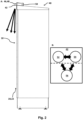
- Fig. 1 illustrates a parcel locker 10 equipped with an illumination unit 40.
- the parcel locker 10 has a plurality of compartments 20 including gates 22 with lock units for controlling access to the compartments.
- the cut-out only shows three compartments 20 and gates 22, however the parcel locker 10 can have any number of compartments such as 10, 13, 16, 20 or more compartments 20.
- the parcel locker 10 comprises a first short-range communication unit 30 with a first antenna 32 for short-range communication with a third-party device 90.
- the first short-range communication unit 30 may be configured to communicate using Bluetooth or ZigBee.
- the parcel locker 10 comprises a parcel locker controller configured for instructing the lock units to open as a function of instruction received by a third-party device 90.
- the parcel locker 10 comprises a first energy storage for powering the parcel locker 10.
- the first energy storage may be a battery and it will typically be installed on the inside of the parcel locker 10.
- the parcel locker 10 further comprises an illumination unit 40 arranged on the parcel locker 10 for illumination at least part of an area surrounding the parcel locker 10.
- the illumination unit 40 has a light emitter 42 for emitting light, in the shown embodiment the light emitter 42 is a strip of LEDs but other light emitting units can be used.
- the illumination unit 40 has an illumination short-range communication unit 46 (not shown in this figure) having a second antenna 48 (not shown in this figure) for short-range communication with a third-party device 90.
- the illumination unit 40 further has an illumination controller 50 (not shown in this figure) comprising at least one processor and at least one memory that includes program code, wherein the memory and the program code is configured to cause the processor to turn on the light emitter 42 or increase illumination output of the light emitter 42 as a function of instructions received directly from a third-party device 90.
- an illumination controller 50 comprising at least one processor and at least one memory that includes program code, wherein the memory and the program code is configured to cause the processor to turn on the light emitter 42 or increase illumination output of the light emitter 42 as a function of instructions received directly from a third-party device 90.
- the illumination unit 40 will comprise an illumination energy storage for powering the illumination unit 40.
- This illumination energy storage is a separate unit to the first energy storage.
- the illumination energy storage may be a battery.
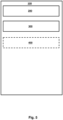
- Fig. 2 illustrates another parcel locker 10 equipped with an illumination unit 40 and states 52, 54, 56 of a light emitter 42.
- the parcel locker 10 has a plurality of compartments 20 including gates 22 with lock units for controlling access to the compartments.
- the view of Fig. 2A is a sideview, thus the plurality of compartments 20 including gates 22 are not visible.
- the parcel locker 10 comprises a first short-range communication unit 30 with a first antenna 32 for short-range communication with a third-party device 90.
- the first short-range communication unit 30 may be configured to communicate using Bluetooth or ZigBee.
- the parcel locker 10 has a first energy storage for powering the parcel locker 10.
- the first energy storage may be a battery and it will typically be installed on the inside of the parcel locker 10.
- the parcel locker 10 comprises a parcel locker controller configured for instructing the lock units to open as a function of instruction received by a third-party device 90.
- the parcel locker 10 further comprises an illumination unit 40 arranged on the parcel locker 10 for illumination at least part of an area surrounding the parcel locker 10.
- the illumination unit 40 has a light emitter 42 for emitting light, in the shown embodiment the light emitter 42 is a strip of LEDs but other light emitting units can be used.
- the illumination unit 40 has an illumination short-range communication unit 46 having a second antenna 48 for short-range communication with a third-party device 90.
- the illumination unit 40 further has an illumination controller 50 comprising at least one processor and at least one memory that includes program code, wherein the memory and the program code is configured to cause the processor to turn on the light emitter 42 or increase illumination output of the light emitter 42 as a function of instructions received directly from a third-party device 90.
- an illumination controller 50 comprising at least one processor and at least one memory that includes program code, wherein the memory and the program code is configured to cause the processor to turn on the light emitter 42 or increase illumination output of the light emitter 42 as a function of instructions received directly from a third-party device 90.
- the illumination unit 40 will comprise an illumination energy storage for powering the illumination unit 40.
- This illumination energy storage is a separate unit to the first energy storage.
- the illumination energy storage may be a battery.
- the illumination energy storage is stored within the box containing the illumination controller 50
- Fig. 2B shows states of the light emitter 42.
- the light emitter 42 comprises the following states;
- the memory and the program code are configured to cause the processor to change the state of the light emitter 42 as a function of received instructions or as a function of a pre-set time period.
- the memory and the program code are also configured to change the state of the light emitter from an activated state 52 or dim state 56 to the hibernating state 54 after a pre-set time period. There may be different pre-set time periods for the dim state 54 and the activated state 52.
- Fig. 3 illustrates a parcel locker station 80 comprising at least four parcel lockers 10.
- the four parcel lockers 10 may be the parcel lockers 10 shown in the figures 1 and 2 and having the same features.
- Fig. 4 illustrates a parcel locker station 80 wherein a person interacts using a third-party device 90.
- the parcel locker station 80 may be similar to the parcel locker station 80 shown in figure 3 .
- the party uses the third-party device 90.
- the third-party device 90 sends a first set of instructions to a specific parcel locker 10 of the parcel lockers 10 for interacting with said specific parcel locker 10.
- the third-party device 90 sends a second set of instructions to said illumination unit 40 paired with said specific parcel locker 10, wherein the second set of instructions causes said illumination unit 40 to perform a step of activating 300 a light emitter 42 for illuminating at least part of an area surrounding the parcel locker 10.
- the second set of instructions may also be intercepted by the other or neighboring illumination units 40 and these illumination units 40 perform a step of changing a state of their light emitters to a dim state 56 i.e. at a lower power compared to the light emitter 42 of said illumination unit 40 paired with said specific parcel locker 10.
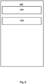
- Fig. 5 illustrates a method 100 for controlling an illumination unit 40 when a party interacts with a parcel locker 10.
- the method 100 comprises a step of sending 200 from a third-party device 90 a first set of instructions to a parcel locker 10 for interacting with the parcel locker 10 and a second set of instructions to the illumination unit 40, wherein the second set of instructions causes the illumination unit 40 to perform a step of activating 300 a light emitter 42 for illuminating at least part of an area surrounding the parcel locker 10.
- the method 100 may optionally include a further step of sending 200 from a third-party device 90 a third set of instructions to the illumination unit 40, wherein the third set of instructions causes the illumination unit 40 to perform a step of deactivating 400 the light emitter 42.
- Fig. 6 illustrates a method 1000 for globally parring an illumination unit 40 and a parcel locker 10.
- the method 1000 comprises steps of
- the illumination unit 40 may be similar to the embodiments shown in figures 1-4 .
Abstract
An illumination unit (40) configured to be installed on a parcel locker (10), wherein the illumination unit (40) comprising- means for attachment to a parcel locker (10);- a light emitter (42) for emitting light;- an illumination short-range communication unit (46) comprising a second antenna (48) for short-range communication with a third-party device (90),- an illumination controller (50) comprising at least one processor and at least one memory that includes program code, wherein the memory and the program code is configured to cause the processor toturn on the light emitter (42) or increase illumination output of the light emitter (42) as a function of instructions received directly from a third-party device (90).
Description
- The present invention relates to a parcel locker configured for illuminating at least part of a surrounding of the parcel locker when a party uses the parcel locker such as collecting a package from the parcel locker or placing a package in the parcel locker.
- The present invention relates to a method for controlling illumination from an illumination unit when a party communicates with a parcel locker such that at least part of an area surrounding the parcel locker is illuminated.
- Parcel lockers are well known systems for reducing last mile costs for distribution of packages. The parcel lockers are placed at various locations such as at gas stations or inside stores and parking lots of stores and so on. In many cases, it is preferred that the parcel lockers are positioned outside because it allows for collection and delivery of packages all day and night irrespective of a store's opening hours.
- At night, the visibility is poor at many parcel lockers, which makes the collection or delivery of package feel less safe. Many parcels which are directly connected to a power line solves this by having a lighting unit such that the visibility is improved, and the light may be turned on the entire night. However, for lean parcel lockers i.e. parcel lockers which are solely powered by a local energy storage such as a battery, this is not an option.
- However, in some cases the parcel locker is off grid and is only powered by a local energy storage. Thus, if the same solution is used as the on-grid parcel lockers then the local energy storage would be drained by the illumination unit in days or weeks. The requirement of many off-grid parcel lockers is that the parcel locker must have sufficient energy for one, two or more years such as ten years.
- A company named iBoxen has tried to solve this problem by including a PIR sensor which activates a light emitter. However, parcel lockers are positioned at places frequented by people and the PIR sensor will activate the light emitter by movement. As a result, the power is drained from the battery to quickly. Thus, there is a need for an improved lean parcel locker and method for illuminating at least part of an area surrounding the parcel locker.
- It is an object to provide a parcel locker and a method controlling illumination from an illumination unit when a party communicates with a parcel locker such that energy consumption is decreased as much as possible.
- It is an obj ect to provide an illumination unit for retrofitting on any parcel locker without an illumination unit. It is furthermore an object to provide a method for parring an illumination unit and a parcel locker.
- An object of the invention is achieved by a parcel locker for distribution of packages. The parcel locker comprises
- a plurality of compartments including gates with lock units for controlling access to the compartments,
- a first short-range communication unit comprising a first antenna for short-range communication with a third-party device,
- a parcel locker controller configured for instructing the lock units to open as a function of instruction received by a third-party device;
- a first energy storage for powering the parcel locker, and
- an illumination unit arranged on the parcel locker for illuminating at least part of an area surrounding the parcel locker, the illumination unit comprises
- a light emitter for emitting light;
- an illumination short-range communication unit comprising a second antenna for short-range communication with a third-party device, and
- an illumination controller comprising at least one processor and at least one memory that includes program code, wherein the memory and the program code is configured to cause the processor to
turn on the light emitter or increase illumination output of the light emitter as a function of instructions received directly from a third-party device.
- Thereby, a parcel locker powered by a first energy storage which is capable of illuminating at least part of an area surrounding the parcel locker is provided, which only uses power for illuminating when instructed by a third-party device. The third-party device will only interact with the parcel locker when delivering packages or collecting packages or performing maintenance of the parcel locker. Thereby, the power for illuminating is reduced significantly especially when compared to parcel lockers using PIR sensors. This is achieved by the illumination unit being configured to only active the light emitter when receiving instructions from a third-party device. In these cases, the light emitter is turned on i.e. the state of the light emitter is changed from a hibernation state to an activated state or illumination output is increased i.e. the state of the light emitter is changed from a dim state to an activated state.
- The memory and the program code may further be configured to turn off the light emitter i.e. change the state of the light emitter to a hibernation state as a function of a pre-set period and/or the memory and the program code may further be configured to turn off the light emitter i.e. change the state of the light emitter to a hibernation state as a function of instruction by the third party device. Thereby, it is prevented that the illumination unit uses to much power.
- The parcel locker may be similar to the parcel locker described in
EP3755187 with an addition of the described illumination unit. Furthermore, the communication using a third-party device with the parcel locker may be as described inEP3755187 orWO2019161870 . This is not as such part of the present invention, however in most cases the parcel locker will be configured for communicating with a distribution server through the third-party device. Thus, the parcel locker controller may function as described in these patent applications. - The parcel locker controller and the illumination controller are separate devices where the parcel locker controller controls the parcel locker while the illumination controller controls the illumination unit.
- In most embodiments, the third-part device will be a smart phone, mobile device or tablet.
- The first energy storage may be one or more batteries such as Li-based batteries. In some embodiments the first energy storage includes a hydrogen storage and a fuel cell or methane storage and a fuel cell.
- The first short-range communication unit and the illumination short-range communication unit may include Bluetooth, NFC, RFID, ZigBee or similar low-power communication protocols. However, it is preferred that the illumination short-range communication unit uses Bluetooth or ZigBee as it would otherwise require that the third-party device is very close to the illumination short-range communication unit in order to establish a communication.
- The third-party device may send instructions to the illumination unit as a function of the local time at the smart device and the latitude position of the parcel locker.
- The illumination unit may be integrated into the parcel locker, or the illumination unit may be an addon retrofitted to one or more outer surfaces of the parcel locker. However, even if the illumination unit is integrated into the parcel locker, then the illumination unit and the parcel locker are still two separate units which are only linked mechanically. This ensures that the illumination unit does not siphon any local energy from the parcel locker.
- In an aspect of the invention, the light emitter may comprise a LED strip and/or a plurality of LEDs and/or halogen bulb and/or a sodium vapor lamp or another energy efficient light emitter. The LED strip and/or the plurality of LEDs are at the moment the most energy efficient light emitters, however other light emitters can be used.
- In an embodiment, the light emitter may be a LED strip and/or a plurality of LEDs extending downwards between two columns of compartments. However, the invention is not limited to any specific position of the light emitter.
- In an aspect of the invention, the parcel locker may comprise a front side with at least one compartment and the light emitter is arranged for illuminating at least part of the front side. Thereby, energy is saved as only the front side is illuminated i.e. there is no need to illuminate a back side which is not used for collecting a package.
- In the case, where the parcel locker has two or more sides with compartments, then the light emitter is arranged to illuminate the two or more sides with compartments. In this case the memory and the program code may be configured to cause the processor to only turn on the light emitter on the side from where a package is to be delivered or collected. The memory and the program code may further be configured to changing the state of light emitter on the other sides to a dim state.
- In an embodiment, the parcel locker comprises a flange extending from the parcel locker, wherein the flange is positioned above one of the gates or positioned above the gates, and the light emitter is arranged on the flange for illuminating an area below the flange. The flange may be on the front side. The flange is a simple mechanical solution for illuminating a front or side of the parcel locker.
- In an aspect of the invention, wherein the first short-range communication unit and the illumination short-range communication unit may communicate on two different channels. This will simplify communications as cross communication is limited.
- In an aspect of the invention, wherein the illumination unit comprises an illumination energy storage for powering the illumination unit.
- The illumination energy storage is separate to the first energy storage. However, the illumination energy storage may be one or more batteries such as Li-based batteries. In some embodiments the first energy storage includes a hydrogen storage and a fuel cell or methane storage and a fuel cell.
- For many parcel lockers the first energy storage is dimensioned to fit a life cycle of a parcel locker such that the first energy storage is depleted at the end of the life cycle of the parcel locker. Similar, the illumination energy storage may be dimensioned to fit the life cycle of a parcel locker such that the illumination energy storage does not need to be replaced.
- In an aspect of the invention, wherein the memory and the program code may further be configured to cause the processor to set the light emitter at a dim state, when the illumination short-range communication unit intercept instruction for another illumination unit.
- Thereby, if two or more parcel lockers are positioned near one another or along a line, then the parcel locker which a person handling the third-party device wishes to interact with is set in an activated state, wherein the light emitter of this parcel locker is emitting light at a first power level. The short-range communication units of the other parcel lockers may intercept this instruction, and this will cause the light emitters of these other parcel lockers to set to a dim state. The light emitters in the dim state will emit light at a second power level being lower than the first power level.
- An object of the invention is achieved by a parcel locker station for distribution of packages. The parcel locker station comprises two or more of the parcel lockers, wherein the two or more of the parcel lockers include at least one parcel locker as described in this application.
- The parcel lockers may be positioned along a line as shown in
figure 3 and4 . - In an embodiment, at least two, three or all of the parcel lockers are according to one of the earlier described embodiments of parcel lockers and/or according to the anyone of claims 1-6.
- If the memory and the program code of the parcel lockers are configured to cause the processor to set the light emitter at a dim state, when the illumination short-range communication unit intercept instruction for another illumination unit. Then the power required for illuminating the parcel locker for which the instruction is intended can be reduced - i.e. the light emitter of this parcel locker may emit light at the first power level which can be reduced compared to a light emitter emitting light without neighboring parcel lockers emitting at a dim state. The total power consumption used for illuminating the parcel locker station may still be greater than for a single parcel locker illuminating at a higher first power level however many light emitters are more efficient at lower currents, thus the lux per watt may still be greater for the parcel locker station.
- An object of the invention is achieved by an illumination unit configured to be installed on a parcel locker. The illumination unit comprising
- means for attachment to a parcel locker,
- a light emitter for emitting light,
- an illumination short-range communication unit comprising a second antenna for short-range communication with a third-party device,
- an illumination controller comprising at least one processor and at least one memory that includes program code, wherein the memory and the program code is configured to cause the processor to
turn on the light emitter or increase illumination output of the light emitter as a function of instructions received directly from a third-party device. - Thereby, an illumination unit is provided that can be installed or retrofitted to any parcel locker even on-grid parcel lockers. The illumination unit will be configured to illuminating at least part of an area surrounding the parcel locker on which the illumination unit is installed. Thereby, the retrofitted parcel locker will have all the positive effects previously described. The effect is even possible for a parcel locker being on-grid, since illumination an entire night or when activated by a PIR sensor is expensive as electric energy is expensive. Thus, the illumination unit can even make an on-grid parcel locker more energy efficient.
- The means for attachment to a parcel locker may be magnets or complementary apertures and screws or complementary apertures and bolts or the means may be plate adapted, glued or welded to a surface of a parcel locker. The invention is not limited to how the illumination unit is attached to a parcel locker as there is many solutions known to the skilled person.
- In this embodiment the illumination unit is connected to the power supply of the parcel locker or a first energy storage of the parcel locker.
- In an aspect of the invention, wherein the illumination unit may comprise an illumination energy storage for powering the illumination unit. Thereby, the installation of the illumination unit is greatly simplified as the illumination unit only needs to be retrofitted on the parcel locker with very few invasive actions.
- A country the size of Denmark may presently have more than 1000 parcel lockers without any light emitters, thus the simpler it is to retrofit a parcel locker the better, as this will decrease retrofitting time and thus total costs.
- The illumination energy storage may be as described earlier in the present application.
- In an aspect of the invention, wherein the light emitter may comprise the following states;
- an activated state, wherein the light emitter is emitting light at a first power level;
- a hibernation state, where the light emitter is turned off, and
- optionally a dim state, where the light emitter is emitting light at a second power level being lower than the first power level; and
- This simple programming will decrease energy needed for each interaction with the illumination unit. The dim state will in most cases only be a possible state when the parcel locker has one or more neighboring parcel lockers, however the state may be enabled even if there is no other neighboring parcel locker.
- The illumination unit may be associated with a unique illumination ID number and if the illumination short-range communication unit intercepts instruction to set the light emitter in the activated state and wherein these instructions are associated with an illumination ID number being different than the unique illumination ID, then the memory and the program code are configured to cause the processor to change the state of the light emitter to a dim state from the hibernation state. In the rare cases where the light emitter is already in the activated state, then the memory and the program code are configured to not change the state of the light emitter.
- In some cases, the third-party device will send instruction to the illumination unit to change the state of the light emitter to the hibernating state after a package has been delivered or collected or after maintenance. However, this is unreliable thus in most cases, the memory and the program code are also configured to change the state of the light emitter to the hibernating state after a pre-set time period. There may be different pre-set time periods for the dim state and the activated state.
- The light emitter may go from an activated state to dim state to the hibernating state such that the illumination does not go dark directly after collecting a package at night.
- An object of the invention is achieved by a method for controlling an illumination unit when a party interacts with a parcel locker. The method comprises a step of sending from a third-party device a first set of instructions to the parcel locker for interacting with the parcel locker and a second set of instructions to the illumination unit, wherein the second set of instructions causes the illumination unit to perform a step of activating a light emitter for illuminating at least part of an area surrounding the parcel locker; and optionally the method includes a further step of sending from a third-party device a third set of instructions to the illumination unit, wherein the third set of instructions causes the illumination unit to perform a step of deactivating the light emitter.
- Thus, the method involves the third-party device sending two sets of instructions. The first set of instructions are directed for operation of the parcel locker. The second set of instructions are directed for controlling the illumination unit such that the illumination unit only increases light illumination when instructed to, and this enables an off-grid parcel locker to have an illumination unit without a need for continuously changing or recharging a local energy storage. The effect is greatest for an off-grid parcel locker, such as a battery-powered parcel locker, however there is still an effect even if the parcel locker is connected to an electricity grid, as the method is energy efficient.
- The light emitter may turn off after a pre-set period or optionally the third-party device sends a third set of instructions causing the illumination unit to perform a step of deactivating the light emitter.
- In an aspect of the invention, wherein the light emitter comprises the following states;
- an activated state, wherein the light emitter is emitting light at a first power level;
- a hibernation state, where the light emitter is turned off, and
- optionally a dim state, where the light emitter is emitting light at a second power level being lower than the first power level;
- This simple programming will decrease energy needed for each interaction with the illumination unit. The dim state will in most cases only be a possible state when the parcel locker has one or more neighboring parcel lockers, however the state may be enabled even if there is no other neighboring parcel locker.
- In some cases, the third-party device will send instruction to the illumination unit to change the state of the light emitter to the hibernating state after a package has been delivered or collected or after maintenance. However, this is unreliable thus in most cases, the memory and the program code are also configured to change the state of the light emitter to the hibernating state after a pre-set time period. There may be different pre-set time periods for the dim state and the activated state.
- The light emitter may go from an activated state to dim state to the hibernating state such that the illumination does not go dark directly after collecting a package at night.
- In an aspect of the invention, wherein the illumination unit is associated with a unique illumination ID number and when the second set of instructions has an illumination ID number being different than the unique illumination ID number, then the illumination unit is configured to perform a step of changing the state of the light emitter to a dim state.
- The illumination unit may be associated with a unique illumination ID number and if the illumination short-range communication unit intercepts instruction to set the light emitter in the activated state and wherein these instructions are associated with an illumination ID number being different than the unique illumination ID, then the memory and the program code are configured to cause the processor to change the state of the light emitter to a dim state from the hibernation state.
- In the rare cases where the light emitter is already in the activated state, then the memory and the program code are configured to not change the state of the light emitter.
- In an aspect of the invention, wherein the parcel locker is according to one or more of the previously described embodiments and/or the illumination unit is according to one or more of the previously described embodiments.
- In some embodiments, the parcel locker is according to anyone of claims 1-6 and/or the illumination unit is according to anyone of claims 8 to 10.
- An object of the invention is achieved by a method for globally parring an illumination unit and a parcel locker, the method comprises steps of
- installing an illumination unit according to anyone of previously described embodiments, such as according to anyone of claims 8-10, on a parcel locker, wherein the illumination unit being associated with a unique illumination ID number and the parcel locker being associated with a unique parcel locker ID number; and
- parring at a server side the unique illumination ID number and the unique parcel locker ID number.
- The parring at the server side will ensure that a third-party device will know which illumination unit to send instruction to change a state to activated state or to turn on the light emitter. Thus, the parring is in effect a global parring as the third-party device will always communicate with a distribution server on the server side. Furthermore, the method enables retrofitting of an illumination unit to an already existing parcel locker.
- The parcel locker may be a parcel locker described in one or more of the earlier embodiments or in the embodiments disclosed in the figures. The parcel locker may be according to anyone of claim 1-6 without an illumination unit before installation. The parcel locker may be a lean parcel locker i.e. a battery-powered parcel locker such as the lean locker sold by SwipBox.
- The step of parring at a server side the unique illumination ID number and the unique parcel locker ID number may be performed by storing the paired unique illumination ID number and the unique parcel locker ID on computer readable medium on the server side. A distribution server would be configured to be able read and share the stored paired unique illumination ID number and the unique parcel locker ID to a third-party device which is to collect a parcel or is to deliver a parcel to the parcel locker with the paired illumination unit.
- An object of the invention is achieved by a program code comprising instructions to cause the battery-powered parcel locker as previously described and/or the illumination unit as previously described to execute the steps of the method for controlling an illumination unit when a party interacts with a parcel locker as previously described.
- An object of the invention is achieved by a computer readable medium having stored thereon the program code as previously described.
- Embodiments of the invention will be described in the figures, whereon:
-
Fig. 1 illustrates a parcel locker equipped with an illumination unit; -
Fig. 2 illustrates a parcel locker equipped with an illumination unit and states of a light emitter; -
Fig. 3 illustrates a parcel locker station comprising at least four parcel lockers; -
Fig. 4 illustrates a parcel locker station wherein a person interacts using a third-party device; -
Fig. 5 illustrates a method for controlling an illumination unit when a party interacts with a parcel locker; and -
Fig. 6 illustrates a method for globally parring an illumination unit and a parcel locker. -
Item No Parcel locker 10 Compartment 20 Gate 22 Short-range communication unit 30 First antenna 32 Illumination unit 40 Light emitter 42 Illumination short-range communication unit 46 second antenna 48 Illumination controller 50 Activated state 52 Hibernation state 54 Dim state 56 Battery 70 Parcel locker station 80 Third- party device 90 Method for controlling an illumination unit 100 Sending 200 Activating 300 Deactivating 400 Changing 500 Method for globally parring an illumination unit and a parcel locker 1000 Installing 1100 Parring 1200 -
Fig. 1 illustrates aparcel locker 10 equipped with anillumination unit 40. - The
parcel locker 10 has a plurality ofcompartments 20 includinggates 22 with lock units for controlling access to the compartments. The cut-out only shows threecompartments 20 andgates 22, however theparcel locker 10 can have any number of compartments such as 10, 13, 16, 20 or more compartments 20. - The
parcel locker 10 comprises a first short-range communication unit 30 with a first antenna 32 for short-range communication with a third-party device 90. The first short-range communication unit 30 may be configured to communicate using Bluetooth or ZigBee. - The
parcel locker 10 comprises a parcel locker controller configured for instructing the lock units to open as a function of instruction received by a third-party device 90. - The
parcel locker 10 comprises a first energy storage for powering theparcel locker 10. The first energy storage may be a battery and it will typically be installed on the inside of theparcel locker 10. - The
parcel locker 10 further comprises anillumination unit 40 arranged on theparcel locker 10 for illumination at least part of an area surrounding theparcel locker 10. Theillumination unit 40 has alight emitter 42 for emitting light, in the shown embodiment thelight emitter 42 is a strip of LEDs but other light emitting units can be used. - The
illumination unit 40 has an illumination short-range communication unit 46 (not shown in this figure) having a second antenna 48 (not shown in this figure) for short-range communication with a third-party device 90. - The
illumination unit 40 further has an illumination controller 50 (not shown in this figure) comprising at least one processor and at least one memory that includes program code, wherein the memory and the program code is configured to cause the processor to turn on thelight emitter 42 or increase illumination output of thelight emitter 42 as a function of instructions received directly from a third-party device 90. - In most cases the
illumination unit 40 will comprise an illumination energy storage for powering theillumination unit 40. This illumination energy storage is a separate unit to the first energy storage. The illumination energy storage may be a battery. -
Fig. 2 illustrates anotherparcel locker 10 equipped with anillumination unit 40 and states 52, 54, 56 of alight emitter 42. - The
parcel locker 10 has a plurality ofcompartments 20 includinggates 22 with lock units for controlling access to the compartments. The view of Fig. 2A is a sideview, thus the plurality ofcompartments 20 includinggates 22 are not visible. - The
parcel locker 10 comprises a first short-range communication unit 30 with a first antenna 32 for short-range communication with a third-party device 90. The first short-range communication unit 30 may be configured to communicate using Bluetooth or ZigBee. Theparcel locker 10 has a first energy storage for powering theparcel locker 10. The first energy storage may be a battery and it will typically be installed on the inside of theparcel locker 10. - The
parcel locker 10 comprises a parcel locker controller configured for instructing the lock units to open as a function of instruction received by a third-party device 90. - The
parcel locker 10 further comprises anillumination unit 40 arranged on theparcel locker 10 for illumination at least part of an area surrounding theparcel locker 10. Theillumination unit 40 has alight emitter 42 for emitting light, in the shown embodiment thelight emitter 42 is a strip of LEDs but other light emitting units can be used. - The
illumination unit 40 has an illumination short-range communication unit 46 having a second antenna 48 for short-range communication with a third-party device 90. - The
illumination unit 40 further has anillumination controller 50 comprising at least one processor and at least one memory that includes program code, wherein the memory and the program code is configured to cause the processor to turn on thelight emitter 42 or increase illumination output of thelight emitter 42 as a function of instructions received directly from a third-party device 90. - In most cases the
illumination unit 40 will comprise an illumination energy storage for powering theillumination unit 40. This illumination energy storage is a separate unit to the first energy storage. The illumination energy storage may be a battery. In the present embodiment the illumination energy storage is stored within the box containing theillumination controller 50 - Fig. 2B shows states of the
light emitter 42. Thelight emitter 42 comprises the following states; - an activated
state 52, wherein thelight emitter 42 is emitting light a first power level; and - a
hibernation state 54, where thelight emitter 42 is turned off; and - optionally a dim state (56), where the light emitter (42) is emitting light at a second power level being lower than the first power level.
- The memory and the program code are configured to cause the processor to change the state of the
light emitter 42 as a function of received instructions or as a function of a pre-set time period. - In most cases, the memory and the program code are also configured to change the state of the light emitter from an activated
state 52 ordim state 56 to the hibernatingstate 54 after a pre-set time period. There may be different pre-set time periods for thedim state 54 and the activatedstate 52. -
Fig. 3 illustrates aparcel locker station 80 comprising at least fourparcel lockers 10. The fourparcel lockers 10 may be theparcel lockers 10 shown in thefigures 1 and2 and having the same features. -
Fig. 4 illustrates aparcel locker station 80 wherein a person interacts using a third-party device 90. Theparcel locker station 80 may be similar to theparcel locker station 80 shown infigure 3 . - The party (person) uses the third-
party device 90. The third-party device 90 sends a first set of instructions to aspecific parcel locker 10 of theparcel lockers 10 for interacting with saidspecific parcel locker 10. At the same time, the third-party device 90 sends a second set of instructions to saidillumination unit 40 paired with saidspecific parcel locker 10, wherein the second set of instructions causes saidillumination unit 40 to perform a step of activating 300 alight emitter 42 for illuminating at least part of an area surrounding theparcel locker 10. The second set of instructions may also be intercepted by the other or neighboringillumination units 40 and theseillumination units 40 perform a step of changing a state of their light emitters to adim state 56 i.e. at a lower power compared to thelight emitter 42 of saidillumination unit 40 paired with saidspecific parcel locker 10. -
Fig. 5 illustrates amethod 100 for controlling anillumination unit 40 when a party interacts with aparcel locker 10. Themethod 100 comprises a step of sending 200 from a third-party device 90 a first set of instructions to aparcel locker 10 for interacting with theparcel locker 10 and a second set of instructions to theillumination unit 40, wherein the second set of instructions causes theillumination unit 40 to perform a step of activating 300 alight emitter 42 for illuminating at least part of an area surrounding theparcel locker 10. Themethod 100 may optionally include a further step of sending 200 from a third-party device 90 a third set of instructions to theillumination unit 40, wherein the third set of instructions causes theillumination unit 40 to perform a step of deactivating 400 thelight emitter 42. -
Fig. 6 illustrates amethod 1000 for globally parring anillumination unit 40 and aparcel locker 10. Themethod 1000 comprises steps of - installing 1100 an
illumination unit 40 on aparcel locker 10, wherein theillumination unit 40 comprises a unique illumination ID number and theparcel locker 10 comprises a unique parcel locker ID number; and - parring 1200 at a server side the unique illumination ID number and the unique parcel locker ID number.
- The
illumination unit 40 may be similar to the embodiments shown infigures 1-4 .
Claims (17)
- A parcel locker (10) for distribution of packages, wherein the parcel locker (10) comprises- a plurality of compartments (20) including gates (22) with lock units for controlling access to the compartments,- a first short-range communication unit (30) comprising a first antenna (32) for short-range communication with a third-party device (90),- a parcel locker controller configured for instructing the lock units to open as a function of instruction received by a third-party device (90);- a first energy storage for powering the parcel locker (10), and- an illumination unit (40) arranged on the parcel locker (10) for illuminating at least part of an area surrounding the parcel locker (10), the illumination unit (40) comprises- a light emitter (42) for emitting light;- an illumination short-range communication unit (46) comprising a second antenna (48) for short-range communication with a third-party device (90), and- an illumination controller (50) comprising at least one processor and at least one memory that includes program code, wherein the memory and the program code is configured to cause the processor to
turn on the light emitter (42) or increase illumination output of the light emitter (42) as a function of instructions received directly from a third-party device (90). - A parcel locker according to claim 1, wherein the light emitter (42) comprises a LED strip and/or a plurality of LEDs and/or halogen bulb and/or a sodium vapor lamp.
- A parcel locker (10) according to claim 1 or 2, wherein the parcel locker (10) comprises a front side with at least one compartment (20) and the light emitter (42) is arranged for illuminating at least part of the front side.
- A parcel locker (10) according to anyone of claims 1 to 3, wherein first short-range communication unit (30) and the illumination short-range communication unit (46) communicates on two different channels.
- A parcel locker (10) according to anyone of claims 1 to 4, wherein the illumination unit (40) comprises an illumination energy storage for powering the illumination unit (40).
- A parcel locker (10) according to anyone of claims 1 to 5, wherein the memory and the program code is further configured to cause the processor to set the light emitter (42) at a dim state, when the illumination short-range communication unit (46) intercept instruction for another illumination unit (40).
- A parcel locker station (80) for distribution of packages, wherein the parcel locker station (10) comprises two or more of the parcel lockers (10), wherein the two or more of the parcel lockers (10) include at least one parcel locker (10) according to anyone of claims 1-6.
- An illumination unit (40) configured to be installed on a parcel locker (10), wherein the illumination unit (40) comprising- means for attachment to a parcel locker (10);- a light emitter (42) for emitting light;- an illumination short-range communication unit (46) comprising a second antenna (48) for short-range communication with a third-party device (90),- an illumination controller (50) comprising at least one processor and at least one memory that includes program code, wherein the memory and the program code is configured to cause the processor to
turn on the light emitter (42) or increase illumination output of the light emitter (42) as a function of instructions received directly from a third-party device (90). - An illumination unit (40) according to claim 8, wherein the illumination unit (40) comprises an illumination energy storage for powering the illumination unit (40).
- An illumination unit (40) according to claim 8 or 9, wherein the light emitter (42) comprises the following states;- an activated state (52), wherein the light emitter (42) is emitting light at a first power level;- a hibernation state (54), where the light emitter (42) is turned off, and- optionally a dim state (56), where the light emitter (42) is emitting light at a second power level being lower than the first power level;wherein the memory and the program code are configured to cause the processor to change the state of the light emitter (42) as a function of received instructions or as a function of a pre-set time period.
- A method (100) for controlling an illumination unit (40) when a party interacts with a parcel locker (10); wherein the method (100) comprises a step of sending (200) from a third-party device (90) a first set of instructions to the parcel locker (10) for interacting with the parcel locker (10) and a second set of instructions to the illumination unit (40), wherein the second set of instructions causes the illumination unit (40) to perform a step of activating (300) a light emitter (42) for illuminating at least part of an area surrounding the parcel locker (10); and optionally the method (100) includes a further step of sending (200) from a third-party device (90) a third set of instructions to the illumination unit (40), wherein the third set of instructions causes the illumination unit (40) to perform a step of deactivating (400) the light emitter (42).
- A method (100) according to claim 10 or 11, wherein the light emitter (42) comprises the following states;- an activated state (52), wherein the light emitter (42) is emitting light at a first power level;- a hibernation state (54), where the light emitter (42) is turned off, and- optionally a dim state (56), where the light emitter (42) is emitting light at a second power level being lower than the first power level;wherein the illumination unit (40) is configured to perform a step of changing (500) state of the light emitter (42) as a function of received instructions or as a function of a pre-set period.
- A method (100) according to claim 12, wherein the illumination unit (40) is associated with a unique illumination ID number and when the second set of instructions has an illumination ID number being different than the unique illumination ID number, then the illumination unit (40) is configured to perform a step of changing the state of the light emitter (42) to a dim state (56).
- A method (100) according to anyone of claims 11 to 13, wherein the battery-powered parcel locker (10) is according to anyone of claims 1-6 and/or the illumination unit (40) is according to anyone of claims 8 to 10.
- A method (1000) for globally parring an illumination unit (40) and a parcel locker (10), the method (1000) comprises steps of- installing (1100) an illumination unit (40) according to anyone of claims 8 to 10 on a parcel locker (10), wherein the illumination unit (40) comprises a unique illumination ID number and the parcel locker (10) comprises a unique parcel locker ID number; and- parring (1200) at a server side the unique illumination ID number and the unique parcel locker ID number.
- A program code comprising instructions to cause the parcel locker (10) according to anyone of claims 1-6 and/or the illumination unit (40) according to anyone of claims 8 to 10 to execute the steps of the method according to anyone of claims 11 to 13.
- A computer readable medium having stored thereon the program code according to claim 16.
Priority Applications (2)
| Application Number | Priority Date | Filing Date | Title |
|---|---|---|---|
| EP22195969.5A EP4339910A1 (en) | 2022-09-15 | 2022-09-15 | A parcel locker for distribution of packages with third party activated light emitter |
| PCT/EP2023/075279 WO2024056796A1 (en) | 2022-09-15 | 2023-09-14 | A parcel locker for distribution of packages with third party activated light emitter |
Applications Claiming Priority (1)
| Application Number | Priority Date | Filing Date | Title |
|---|---|---|---|
| EP22195969.5A EP4339910A1 (en) | 2022-09-15 | 2022-09-15 | A parcel locker for distribution of packages with third party activated light emitter |
Publications (1)
| Publication Number | Publication Date |
|---|---|
| EP4339910A1 true EP4339910A1 (en) | 2024-03-20 |
Family
ID=83355434
Family Applications (1)
| Application Number | Title | Priority Date | Filing Date |
|---|---|---|---|
| EP22195969.5A Pending EP4339910A1 (en) | 2022-09-15 | 2022-09-15 | A parcel locker for distribution of packages with third party activated light emitter |
Country Status (2)
| Country | Link |
|---|---|
| EP (1) | EP4339910A1 (en) |
| WO (1) | WO2024056796A1 (en) |
Citations (11)
| Publication number | Priority date | Publication date | Assignee | Title |
|---|---|---|---|---|
| US20110121654A1 (en) * | 2006-03-28 | 2011-05-26 | Recker Michael V | Remote switch sensing in lighting devices |
| US20140285113A1 (en) * | 2013-03-22 | 2014-09-25 | International Mobile Iot Corp. | Illumination control system |
| US20140297227A1 (en) * | 2013-03-26 | 2014-10-02 | Sensity Systems, Inc. | System and method for planning and monitoring a light sensory network |
| US20150120601A1 (en) * | 2013-10-25 | 2015-04-30 | Florence Manufacturing Company | Electronically controlled parcel delivery system |
| US20150356801A1 (en) * | 2014-06-02 | 2015-12-10 | Best Lockers, Llc | Mobile kiosk for intelligent securable devices system |
| WO2019161870A1 (en) | 2018-02-23 | 2019-08-29 | Swipbox A/S | Method for allocating parcels and a system therefore |
| US20200021454A1 (en) * | 2017-03-03 | 2020-01-16 | Signify Holding B.V. | Detecting recommissioning |
| EP3671666A1 (en) * | 2018-12-18 | 2020-06-24 | Neopost Technologies | Parcel locker system with autonomous clusters of compartments |
| EP3755187A1 (en) | 2018-02-23 | 2020-12-30 | aCon A/S | Parcel locker and a method for operating the parcel locker |
| US20210076474A1 (en) * | 2019-09-11 | 2021-03-11 | Process4, Inc. | Wirelessly Activated Light |
| EP3806049A1 (en) * | 2019-10-08 | 2021-04-14 | Illinois Tool Works INC. | Secure access locker banks |
-
2022
- 2022-09-15 EP EP22195969.5A patent/EP4339910A1/en active Pending
-
2023
- 2023-09-14 WO PCT/EP2023/075279 patent/WO2024056796A1/en unknown
Patent Citations (11)
| Publication number | Priority date | Publication date | Assignee | Title |
|---|---|---|---|---|
| US20110121654A1 (en) * | 2006-03-28 | 2011-05-26 | Recker Michael V | Remote switch sensing in lighting devices |
| US20140285113A1 (en) * | 2013-03-22 | 2014-09-25 | International Mobile Iot Corp. | Illumination control system |
| US20140297227A1 (en) * | 2013-03-26 | 2014-10-02 | Sensity Systems, Inc. | System and method for planning and monitoring a light sensory network |
| US20150120601A1 (en) * | 2013-10-25 | 2015-04-30 | Florence Manufacturing Company | Electronically controlled parcel delivery system |
| US20150356801A1 (en) * | 2014-06-02 | 2015-12-10 | Best Lockers, Llc | Mobile kiosk for intelligent securable devices system |
| US20200021454A1 (en) * | 2017-03-03 | 2020-01-16 | Signify Holding B.V. | Detecting recommissioning |
| WO2019161870A1 (en) | 2018-02-23 | 2019-08-29 | Swipbox A/S | Method for allocating parcels and a system therefore |
| EP3755187A1 (en) | 2018-02-23 | 2020-12-30 | aCon A/S | Parcel locker and a method for operating the parcel locker |
| EP3671666A1 (en) * | 2018-12-18 | 2020-06-24 | Neopost Technologies | Parcel locker system with autonomous clusters of compartments |
| US20210076474A1 (en) * | 2019-09-11 | 2021-03-11 | Process4, Inc. | Wirelessly Activated Light |
| EP3806049A1 (en) * | 2019-10-08 | 2021-04-14 | Illinois Tool Works INC. | Secure access locker banks |
Also Published As
| Publication number | Publication date |
|---|---|
| WO2024056796A1 (en) | 2024-03-21 |
Similar Documents
| Publication | Publication Date | Title |
|---|---|---|
| ES2909249T3 (en) | Waste storage container | |
| US9210759B2 (en) | Luminaire with ambient sensing and autonomous control capabilities | |
| US7851737B2 (en) | System and method for charging a control device from a lighting system | |
| US7696895B2 (en) | Pathway indicating luminaire | |
| JP6505609B2 (en) | Street light | |
| MY123997A (en) | Light emitting block | |
| ES2673112T3 (en) | Lighting control system | |
| KR200449936Y1 (en) | A stop using solar light | |
| EP4339910A1 (en) | A parcel locker for distribution of packages with third party activated light emitter | |
| US20110304273A1 (en) | Security lighting system | |
| GB2471743A (en) | Street litter bin with solar powered advertising displays | |
| MY127757A (en) | Light emitting tile | |
| US20060279415A1 (en) | Wait Staff Signaling Apparatus | |
| KR100868485B1 (en) | Street lamp of power saving type and the control method to use solar cell | |
| KR101519871B1 (en) | Outdoor automated external defibrillator storage box | |
| KR102239580B1 (en) | Intelligent and natural disaster adaptive control system for wireless street lights powered by solarpanel | |
| GB2347994A (en) | Buoyant illuminating body | |
| US20060042679A1 (en) | Self-contained portable solar power supply system | |
| CN109302782B (en) | Information processing method and device based on intelligent street lamp | |
| JP4976438B2 (en) | Evacuation guidance system | |
| KR200422774Y1 (en) | A lighting system which uses the light of the sun energy. | |
| KR102381357B1 (en) | Emotion lighting using indoor lighting power | |
| CN213237340U (en) | Wisdom garden lighting system | |
| KR102524734B1 (en) | Management system for smart security light | |
| RU215775U1 (en) | MULTIFUNCTIONAL LANTERN |
Legal Events
| Date | Code | Title | Description |
|---|---|---|---|
| PUAI | Public reference made under article 153(3) epc to a published international application that has entered the european phase |
Free format text: ORIGINAL CODE: 0009012 |
|
| STAA | Information on the status of an ep patent application or granted ep patent |
Free format text: STATUS: THE APPLICATION HAS BEEN PUBLISHED |
|
| AK | Designated contracting states |
Kind code of ref document: A1 Designated state(s): AL AT BE BG CH CY CZ DE DK EE ES FI FR GB GR HR HU IE IS IT LI LT LU LV MC MK MT NL NO PL PT RO RS SE SI SK SM TR |