EP4339700A1 - Ouvertures remplaçables, chauffées et pouvant être séchées pour systèmes optiques - Google Patents
Ouvertures remplaçables, chauffées et pouvant être séchées pour systèmes optiques Download PDFInfo
- Publication number
- EP4339700A1 EP4339700A1 EP23195911.5A EP23195911A EP4339700A1 EP 4339700 A1 EP4339700 A1 EP 4339700A1 EP 23195911 A EP23195911 A EP 23195911A EP 4339700 A1 EP4339700 A1 EP 4339700A1
- Authority
- EP
- European Patent Office
- Prior art keywords
- window
- vehicle
- housing
- retainer ring
- threaded portion
- Prior art date
- Legal status (The legal status is an assumption and is not a legal conclusion. Google has not performed a legal analysis and makes no representation as to the accuracy of the status listed.)
- Pending
Links
- 230000003287 optical effect Effects 0.000 title claims abstract description 25
- 238000007789 sealing Methods 0.000 claims abstract description 40
- 230000001681 protective effect Effects 0.000 claims abstract description 8
- 238000000034 method Methods 0.000 claims description 41
- 238000010438 heat treatment Methods 0.000 claims description 13
- 230000008878 coupling Effects 0.000 claims description 6
- 238000010168 coupling process Methods 0.000 claims description 6
- 238000005859 coupling reaction Methods 0.000 claims description 6
- 239000011248 coating agent Substances 0.000 claims description 3
- 238000000576 coating method Methods 0.000 claims description 3
- 230000002209 hydrophobic effect Effects 0.000 claims description 3
- 238000004891 communication Methods 0.000 description 31
- 238000012545 processing Methods 0.000 description 21
- 238000001514 detection method Methods 0.000 description 11
- 230000006870 function Effects 0.000 description 10
- 230000004044 response Effects 0.000 description 9
- 230000005540 biological transmission Effects 0.000 description 8
- 238000013500 data storage Methods 0.000 description 8
- 230000000670 limiting effect Effects 0.000 description 7
- 230000033001 locomotion Effects 0.000 description 7
- 238000011217 control strategy Methods 0.000 description 6
- 230000004438 eyesight Effects 0.000 description 6
- 230000002093 peripheral effect Effects 0.000 description 6
- 230000001133 acceleration Effects 0.000 description 5
- 238000010586 diagram Methods 0.000 description 5
- 239000000463 material Substances 0.000 description 5
- 230000009471 action Effects 0.000 description 4
- 238000010276 construction Methods 0.000 description 4
- 230000007613 environmental effect Effects 0.000 description 4
- 239000000446 fuel Substances 0.000 description 4
- 230000004927 fusion Effects 0.000 description 4
- 238000005259 measurement Methods 0.000 description 4
- 230000003044 adaptive effect Effects 0.000 description 3
- 230000005670 electromagnetic radiation Effects 0.000 description 3
- 238000011156 evaluation Methods 0.000 description 3
- 230000007246 mechanism Effects 0.000 description 3
- 239000011435 rock Substances 0.000 description 3
- 238000001931 thermography Methods 0.000 description 3
- LFQSCWFLJHTTHZ-UHFFFAOYSA-N Ethanol Chemical compound CCO LFQSCWFLJHTTHZ-UHFFFAOYSA-N 0.000 description 2
- 241001465754 Metazoa Species 0.000 description 2
- ATUOYWHBWRKTHZ-UHFFFAOYSA-N Propane Chemical compound CCC ATUOYWHBWRKTHZ-UHFFFAOYSA-N 0.000 description 2
- 241000269400 Sirenidae Species 0.000 description 2
- 230000006399 behavior Effects 0.000 description 2
- 230000010267 cellular communication Effects 0.000 description 2
- 230000008859 change Effects 0.000 description 2
- 238000009833 condensation Methods 0.000 description 2
- 230000005494 condensation Effects 0.000 description 2
- 239000003502 gasoline Substances 0.000 description 2
- 238000013507 mapping Methods 0.000 description 2
- 238000012986 modification Methods 0.000 description 2
- 230000004048 modification Effects 0.000 description 2
- 230000004297 night vision Effects 0.000 description 2
- 230000008447 perception Effects 0.000 description 2
- 230000008569 process Effects 0.000 description 2
- 230000011664 signaling Effects 0.000 description 2
- 230000005236 sound signal Effects 0.000 description 2
- HBBGRARXTFLTSG-UHFFFAOYSA-N Lithium ion Chemical compound [Li+] HBBGRARXTFLTSG-UHFFFAOYSA-N 0.000 description 1
- 239000004642 Polyimide Substances 0.000 description 1
- XUIMIQQOPSSXEZ-UHFFFAOYSA-N Silicon Chemical compound [Si] XUIMIQQOPSSXEZ-UHFFFAOYSA-N 0.000 description 1
- 239000002253 acid Substances 0.000 description 1
- -1 batteries Substances 0.000 description 1
- 230000008901 benefit Effects 0.000 description 1
- 239000003990 capacitor Substances 0.000 description 1
- 230000001427 coherent effect Effects 0.000 description 1
- 238000002485 combustion reaction Methods 0.000 description 1
- 230000007547 defect Effects 0.000 description 1
- 239000000428 dust Substances 0.000 description 1
- 229920001971 elastomer Polymers 0.000 description 1
- 238000005516 engineering process Methods 0.000 description 1
- 239000012530 fluid Substances 0.000 description 1
- 239000002828 fuel tank Substances 0.000 description 1
- 239000011521 glass Substances 0.000 description 1
- 230000003993 interaction Effects 0.000 description 1
- 230000002452 interceptive effect Effects 0.000 description 1
- 239000007788 liquid Substances 0.000 description 1
- 229910001416 lithium ion Inorganic materials 0.000 description 1
- 230000007774 longterm Effects 0.000 description 1
- 239000002184 metal Substances 0.000 description 1
- 238000010295 mobile communication Methods 0.000 description 1
- 239000010705 motor oil Substances 0.000 description 1
- 230000036961 partial effect Effects 0.000 description 1
- 239000003208 petroleum Substances 0.000 description 1
- 239000004033 plastic Substances 0.000 description 1
- 230000010287 polarization Effects 0.000 description 1
- 229920001721 polyimide Polymers 0.000 description 1
- 239000001294 propane Substances 0.000 description 1
- 230000005855 radiation Effects 0.000 description 1
- 230000002441 reversible effect Effects 0.000 description 1
- 239000010980 sapphire Substances 0.000 description 1
- 229910052594 sapphire Inorganic materials 0.000 description 1
- 230000035945 sensitivity Effects 0.000 description 1
- 229910052710 silicon Inorganic materials 0.000 description 1
- 239000010703 silicon Substances 0.000 description 1
- 229920002379 silicone rubber Polymers 0.000 description 1
- 239000004945 silicone rubber Substances 0.000 description 1
- 239000007787 solid Substances 0.000 description 1
- 238000001228 spectrum Methods 0.000 description 1
- 239000000126 substance Substances 0.000 description 1
- 239000000758 substrate Substances 0.000 description 1
- 230000000153 supplemental effect Effects 0.000 description 1
- 238000002834 transmittance Methods 0.000 description 1
- 238000011179 visual inspection Methods 0.000 description 1
- XLYOFNOQVPJJNP-UHFFFAOYSA-N water Substances O XLYOFNOQVPJJNP-UHFFFAOYSA-N 0.000 description 1
Images


Classifications
-
- G—PHYSICS
- G02—OPTICS
- G02B—OPTICAL ELEMENTS, SYSTEMS OR APPARATUS
- G02B27/00—Optical systems or apparatus not provided for by any of the groups G02B1/00 - G02B26/00, G02B30/00
- G02B27/0006—Optical systems or apparatus not provided for by any of the groups G02B1/00 - G02B26/00, G02B30/00 with means to keep optical surfaces clean, e.g. by preventing or removing dirt, stains, contamination, condensation
-
- G—PHYSICS
- G03—PHOTOGRAPHY; CINEMATOGRAPHY; ANALOGOUS TECHNIQUES USING WAVES OTHER THAN OPTICAL WAVES; ELECTROGRAPHY; HOLOGRAPHY
- G03B—APPARATUS OR ARRANGEMENTS FOR TAKING PHOTOGRAPHS OR FOR PROJECTING OR VIEWING THEM; APPARATUS OR ARRANGEMENTS EMPLOYING ANALOGOUS TECHNIQUES USING WAVES OTHER THAN OPTICAL WAVES; ACCESSORIES THEREFOR
- G03B17/00—Details of cameras or camera bodies; Accessories therefor
- G03B17/02—Bodies
- G03B17/08—Waterproof bodies or housings
-
- B—PERFORMING OPERATIONS; TRANSPORTING
- B60—VEHICLES IN GENERAL
- B60S—SERVICING, CLEANING, REPAIRING, SUPPORTING, LIFTING, OR MANOEUVRING OF VEHICLES, NOT OTHERWISE PROVIDED FOR
- B60S1/00—Cleaning of vehicles
- B60S1/02—Cleaning windscreens, windows or optical devices
- B60S1/023—Cleaning windscreens, windows or optical devices including defroster or demisting means
-
- B—PERFORMING OPERATIONS; TRANSPORTING
- B60—VEHICLES IN GENERAL
- B60S—SERVICING, CLEANING, REPAIRING, SUPPORTING, LIFTING, OR MANOEUVRING OF VEHICLES, NOT OTHERWISE PROVIDED FOR
- B60S1/00—Cleaning of vehicles
- B60S1/02—Cleaning windscreens, windows or optical devices
- B60S1/04—Wipers or the like, e.g. scrapers
-
- G—PHYSICS
- G02—OPTICS
- G02B—OPTICAL ELEMENTS, SYSTEMS OR APPARATUS
- G02B7/00—Mountings, adjusting means, or light-tight connections, for optical elements
- G02B7/02—Mountings, adjusting means, or light-tight connections, for optical elements for lenses
- G02B7/026—Mountings, adjusting means, or light-tight connections, for optical elements for lenses using retaining rings or springs
-
- G—PHYSICS
- G03—PHOTOGRAPHY; CINEMATOGRAPHY; ANALOGOUS TECHNIQUES USING WAVES OTHER THAN OPTICAL WAVES; ELECTROGRAPHY; HOLOGRAPHY
- G03B—APPARATUS OR ARRANGEMENTS FOR TAKING PHOTOGRAPHS OR FOR PROJECTING OR VIEWING THEM; APPARATUS OR ARRANGEMENTS EMPLOYING ANALOGOUS TECHNIQUES USING WAVES OTHER THAN OPTICAL WAVES; ACCESSORIES THEREFOR
- G03B30/00—Camera modules comprising integrated lens units and imaging units, specially adapted for being embedded in other devices, e.g. mobile phones or vehicles
-
- G—PHYSICS
- G08—SIGNALLING
- G08G—TRAFFIC CONTROL SYSTEMS
- G08G1/00—Traffic control systems for road vehicles
- G08G1/01—Detecting movement of traffic to be counted or controlled
- G08G1/04—Detecting movement of traffic to be counted or controlled using optical or ultrasonic detectors
-
- H—ELECTRICITY
- H04—ELECTRIC COMMUNICATION TECHNIQUE
- H04N—PICTORIAL COMMUNICATION, e.g. TELEVISION
- H04N23/00—Cameras or camera modules comprising electronic image sensors; Control thereof
- H04N23/50—Constructional details
- H04N23/51—Housings
Definitions
- Optical systems (e.g., cameras) mounted on vehicles may include outer windows that can be subject to impacts from various objects (e.g., rocks) that can chip, scratch, crack, or otherwise damage the windows.
- Conventional solutions include using thicker and/or stronger materials for the optical windows.
- such materials may reduce the image quality of the optical system (e.g., increased optical defects), reduce the optical transmittance of the optical window itself, and/or be expensive to produce and/or replace. Accordingly, a need exists to protect outer windows from various object impacts at a low cost.
- the present disclosure relates to replaceable, heated, and wipeable apertures for optical systems (e.g., cameras) that may provide improved structural properties (e.g., impact resistance) compared to conventional solutions.
- optical systems e.g., cameras
- structural properties e.g., impact resistance
- such optical systems could be mounted on autonomous vehicles.
- an apparatus in a first aspect, includes an optical system with a lens.
- the apparatus also includes a housing in which the lens is disposed.
- the housing has a sealing surface and a threated portion.
- the apparatus further includes a chamfered window that provides a protective aperture for the lens.
- the apparatus also includes a retainer ring that has a retaining portion and a threaded portion. The retaining portion contacts the chamfer of the window while the threaded portion of the retainer ring threads onto the threaded portion of the housing to hold the window against the sealing surface of the housing and form a watertight seal.
- a method in a second aspect, includes attaching a chamfered window to a housing by means of a retainer ring.
- the housing houses a lens of an optical system and further includes a sealing surface.
- the chamfered window is configured to provide a protective aperture for the lens when a retaining portion of the retainer ring contacts the chamfer of the window and the retainer ring further couples to the housing to hold the window against the sealing surface of the housing to form a watertight seal.
- Example methods and systems are contemplated herein. Any example embodiment or feature described herein is not necessarily to be construed as preferred or advantageous over other embodiments or features. Further, the example embodiments described herein are not meant to be limiting. It will be readily understood that certain aspects of the disclosed systems and methods can be arranged and combined in a wide variety of different configurations, all of which are contemplated herein. In addition, the particular arrangements shown in the figures should not be viewed as limiting. It should be understood that other embodiments might include more or less of each element shown in a given figure. Additionally, some of the illustrated elements may be combined or omitted. Yet further, an example embodiment may include elements that are not illustrated in the figures.
- Autonomous vehicles can utilize multiple sensors to obtain information about the external environment for route planning, perception, and navigation.
- sensors can include visible cameras, infrared cameras, and lidar sensors.
- vehicle-mounted sensors can be subject to rock and debris strikes and other types of impacts. Accordingly, it may be desirable to protect the vehicle-mounted sensors by way of an impact-resistant housing and/or optical window, such as a replaceable, heated, and wipeable aperture, to provide improved structural properties (e.g., impact resistance) to cover the sensors.
- an aperture could protect the sensors from dirt, dust, rain, snow, rocks, etc.
- the aperture could be replaceable in case of impact damage.
- the aperture could be heated to maintain acceptable performance of the sensors to be able to collect information about the environment, such as to remove ice and/or condensation or to prevent fogging.
- the aperture could be wipeable to clear condensation, liquids, and/or other obstructions from the field of view of the sensors.
- the aperture can be attachable to a housing for the sensor to hold a window securely in front of the sensor, form a watertight seal, and provide thermal contact with a heater.
- the aperture can include a retainer ring in some embodiments in order to accomplish this. A portion of the retainer ring can have a chamfered edge to align with a chamfered edge on the window to securely couple the two. If damaged, the aperture including the retainer ring and window, can be replaced without having to damage or replace the sensor itself.
- An example system may be implemented in or may take the form of an automobile. Additionally, an example system may also be implemented in or take the form of various vehicles, such as cars, trucks (e.g., pickup trucks, vans, tractors, and tractor trailers), motorcycles, buses, airplanes, helicopters, drones, lawn mowers, earth movers, boats, submarines, all-terrain vehicles, snowmobiles, aircraft, recreational vehicles, amusement park vehicles, farm equipment or vehicles, construction equipment or vehicles, warehouse equipment or vehicles, factory equipment or vehicles, trams, golf carts, trains, trolleys, sidewalk delivery vehicles, robot devices, etc. Other vehicles are possible as well. Further, in some embodiments, example systems might not include a vehicle.
- trucks e.g., pickup trucks, vans, tractors, and tractor trailers
- motorcycles buses, airplanes, helicopters, drones, lawn mowers, earth movers, boats, submarines, all-terrain vehicles, snowmobiles, aircraft, recreational vehicles, amusement park vehicles, farm equipment or vehicles, construction equipment or vehicles, warehouse equipment or vehicles
- FIG. 1 is a functional block diagram illustrating example vehicle 100, which may be configured to operate fully or partially in an autonomous mode. More specifically, vehicle 100 may operate in an autonomous mode without human interaction through receiving control instructions from a computing system. As part of operating in the autonomous mode, vehicle 100 may use sensors to detect and possibly identify objects of the surrounding environment to enable safe navigation. Additionally, example vehicle 100 may operate in a partially autonomous (i.e., semi-autonomous) mode in which some functions of the vehicle 100 are controlled by a human driver of the vehicle 100 and some functions of the vehicle 100 are controlled by the computing system.
- a partially autonomous i.e., semi-autonomous
- vehicle 100 may also include subsystems that enable the driver to control operations of vehicle 100 such as steering, acceleration, and braking, while the computing system performs assistive functions such as lanedeparture warnings / lane-keeping assist or adaptive cruise control based on other objects (e.g., vehicles) in the surrounding environment.
- assistive functions such as lanedeparture warnings / lane-keeping assist or adaptive cruise control based on other objects (e.g., vehicles) in the surrounding environment.
- the human driver in a partially autonomous driving mode, even though the vehicle assists with one or more driving operations (e.g., steering, braking and/or accelerating to perform lane centering, adaptive cruise control, advanced driver assistance systems (ADAS), and emergency braking), the human driver is expected to be situationally aware of the vehicle's surroundings and supervise the assisted driving operations.
- driving operations e.g., steering, braking and/or accelerating to perform lane centering, adaptive cruise control, advanced driver assistance systems (ADAS), and emergency braking
- ADAS advanced driver assistance systems
- emergency braking the human driver is expected to be situationally aware of the vehicle's surroundings and supervise the assisted driving operations.
- the human driver is expected to be responsible for taking control as needed.
- the disclosed systems and methods can be used in SAE Level 3 driving assistance systems capable of autonomous driving under limited (e.g., highway) conditions.
- the disclosed systems and methods can be used in vehicles that use SAE Level 4 self-driving systems that operate autonomously under most regular driving situations and require only occasional attention of the human operator.
- accurate lane estimation can be performed automatically without a driver input or control (e.g., while the vehicle is in motion) and result in improved reliability of vehicle positioning and navigation and the overall safety of autonomous, semi-autonomous, and other driver assistance systems.
- other organizations in the United States or in other countries, may categorize levels of automated driving operations differently.
- the disclosed systems and methods herein can be used in driving assistance systems defined by these other organizations' levels of automated driving operations.
- vehicle 100 may include various subsystems, such as propulsion system 102, sensor system 104, control system 106, one or more peripherals 108, power supply 110, computer system 112 (which could also be referred to as a computing system) with data storage 114, and user interface 116.
- vehicle 100 may include more or fewer subsystems, which can each include multiple elements.
- the subsystems and components of vehicle 100 may be interconnected in various ways.
- functions of vehicle 100 described herein can be divided into additional functional or physical components, or combined into fewer functional or physical components within embodiments.
- the control system 106 and the computer system 112 may be combined into a single system that operates the vehicle 100 in accordance with various operations.
- Propulsion system 102 may include one or more components operable to provide powered motion for vehicle 100 and can include an engine/motor 118, an energy source 119, a transmission 120, and wheels/tires 121, among other possible components.
- engine/motor 118 may be configured to convert energy source 119 into mechanical energy and can correspond to one or a combination of an internal combustion engine, an electric motor, steam engine, or Stirling engine, among other possible options.
- propulsion system 102 may include multiple types of engines and/or motors, such as a gasoline engine and an electric motor.
- Energy source 119 represents a source of energy that may, in full or in part, power one or more systems of vehicle 100 (e.g., engine/motor 118).
- energy source 119 can correspond to gasoline, diesel, other petroleum-based fuels, propane, other compressed gasbased fuels, ethanol, solar panels, batteries, and/or other sources of electrical power.
- energy source 119 may include a combination of fuel tanks, batteries, capacitors, and/or flywheels.
- Transmission 120 may transmit mechanical power from engine/motor 118 to wheels/tires 121 and/or other possible systems of vehicle 100.
- transmission 120 may include a gearbox, a clutch, a differential, and a drive shaft, among other possible components.
- a drive shaft may include axles that connect to one or more wheels/tires 121.
- Wheels/tires 121 of vehicle 100 may have various configurations within example embodiments.
- vehicle 100 may exist in a unicycle, bicycle/motorcycle, tricycle, or car/truck four-wheel format, among other possible configurations.
- wheels/tires 121 may connect to vehicle 100 in various ways and can exist in different materials, such as metal and rubber.
- Sensor system 104 can include various types of sensors, such as Global Positioning System (GPS) 122, inertial measurement unit (IMU) 124, radar 126, lidar 128, camera 130, steering sensor 123, and throttle/brake sensor 125, among other possible sensors.
- GPS Global Positioning System
- IMU inertial measurement unit
- radar 126 radar 126
- lidar 1208 camera 130
- steering sensor 123 lidar 128, camera 130
- steering sensor 123 e.g., a Bosch Sensor system 104
- throttle/brake sensor 125 e.g., a Bosch Sensor system 104
- sensor system 104 may also include sensors configured to monitor internal systems of the vehicle 100 (e.g., O 2 monitor, fuel gauge, engine oil temperature, and brake wear).
- GPS 122 may include a transceiver operable to provide information regarding the position of vehicle 100 with respect to the Earth.
- IMU 124 may have a configuration that uses one or more accelerometers and/or gyroscopes and may sense position and orientation changes of vehicle 100 based on inertial acceleration. For example, IMU 124 may detect a pitch and yaw of the vehicle 100 while vehicle 100 is stationary or in motion.
- Radar 126 may represent one or more systems configured to use radio signals to sense objects, including the speed and heading of the objects, within the surrounding environment of vehicle 100.
- radar 126 may include antennas configured to transmit and receive radio signals.
- radar 126 may correspond to a mountable radar configured to obtain measurements of the surrounding environment of vehicle 100.
- Lidar 128 may include one or more laser sources, a laser scanner, and one or more detectors, among other system components, and may operate in a coherent mode (e.g., using heterodyne detection) or in an incoherent detection mode (i.e., time-of-flight mode).
- the one or more detectors of the lidar 128 may include one or more photodetectors, which may be especially sensitive detectors (e.g., avalanche photodiodes).
- such photodetectors may be capable of detecting single photons (e.g., singlephoton avalanche diodes (SPADs)).
- SPADs singlephoton avalanche diodes
- photodetectors can be arranged (e.g., through an electrical connection in series, etc.) into an array (e.g., as in a silicon photomultiplier (SiPM)).
- the one or more photodetectors are Geiger-mode operated devices and the lidar includes subcomponents designed for such Geiger-mode operation.
- Camera 130 may include one or more devices (e.g., still camera, video camera, a thermal imaging camera, a stereo camera, and a night vision camera) configured to capture images of the surrounding environment of vehicle 100.
- devices e.g., still camera, video camera, a thermal imaging camera, a stereo camera, and a night vision camera
- Steering sensor 123 may sense a steering angle of vehicle 100, which may involve measuring an angle of the steering wheel or measuring an electrical signal representative of the angle of the steering wheel. In some embodiments, steering sensor 123 may measure an angle of the wheels of the vehicle 100, such as detecting an angle of the wheels with respect to a forward axis of the vehicle 100. Steering sensor 123 may also be configured to measure a combination (or a subset) of the angle of the steering wheel, electrical signal representing the angle of the steering wheel, and the angle of the wheels of vehicle 100.
- Throttle/brake sensor 125 may detect the position of either the throttle position or brake position of vehicle 100. For instance, throttle/brake sensor 125 may measure the angle of both the gas pedal (throttle) and brake pedal or may measure an electrical signal that could represent, for instance, an angle of a gas pedal (throttle) and/or an angle of a brake pedal. Throttle/brake sensor 125 may also measure an angle of a throttle body of vehicle 100, which may include part of the physical mechanism that provides modulation of energy source 119 to engine/motor 118 (e.g., a butterfly valve, and a carburetor).
- engine/motor 118 e.g., a butterfly valve, and a carburetor
- throttle/brake sensor 125 may measure a pressure of one or more brake pads on a rotor of vehicle 100 or a combination (or a subset) of the angle of the gas pedal (throttle) and brake pedal, electrical signal representing the angle of the gas pedal (throttle) and brake pedal, the angle of the throttle body, and the pressure that at least one brake pad is applying to a rotor of vehicle 100.
- throttle/brake sensor 125 may be configured to measure a pressure applied to a pedal of the vehicle, such as a throttle or brake pedal.
- Control system 106 may include components configured to assist in navigating vehicle 100, such as steering unit 132, throttle 134, brake unit 136, sensor fusion algorithm 138, computer vision system 140, navigation/pathing system 142, and obstacle avoidance system 144. More specifically, steering unit 132 may be operable to adjust the heading of vehicle 100, and throttle 134 may control the operating speed of engine/motor 118 to control the acceleration of vehicle 100. Brake unit 136 may decelerate vehicle 100, which may involve using friction to decelerate wheels/tires 121. In some embodiments, brake unit 136 may convert kinetic energy of wheels/tires 121 to electric current for subsequent use by a system or systems of vehicle 100.
- Sensor fusion algorithm 138 may include a Kalman filter, Bayesian network, or other algorithms that can process data from sensor system 104.
- sensor fusion algorithm 138 may provide assessments based on incoming sensor data, such as evaluations of individual objects and/or features, evaluations of a particular situation, and/or evaluations of potential impacts within a given situation.
- Computer vision system 140 may include hardware and software (e.g., a general purpose processor such as a central processing unit (CPU), a specialized processor such as a graphical processing unit (GPU) or a tensor processing unit (TPU), an application-specific integrated circuit (ASIC), a field programmable gate array (FPGA), a volatile memory, a nonvolatile memory, one or more machine-learned models) operable to process and analyze images in an effort to determine objects that are in motion (e.g., other vehicles, pedestrians, bicyclists, animals) and objects that are not in motion (e.g., traffic lights, roadway boundaries, speedbumps, and potholes).
- computer vision system 140 may use object recognition, Structure From Motion (SFM), video tracking, and other algorithms used in computer vision, for instance, to recognize objects, map an environment, track objects, estimate the speed of objects, etc.
- SFM Structure From Motion
- Navigation/pathing system 142 may determine a driving path for vehicle 100, which may involve dynamically adjusting navigation during operation. As such, navigation/pathing system 142 may use data from sensor fusion algorithm 138, GPS 122, and maps, among other sources to navigate vehicle 100. Obstacle avoidance system 144 may evaluate potential obstacles based on sensor data and cause systems of vehicle 100 to avoid or otherwise negotiate the potential obstacles.
- vehicle 100 may also include peripherals 108, such as wireless communication system 146, touchscreen 148, interior microphone 150, and/or speaker 152.
- Peripherals 108 may provide controls or other elements for a user to interact with user interface 116.
- touchscreen 148 may provide information to users of vehicle 100.
- User interface 116 may also accept input from the user via touchscreen 148.
- Peripherals 108 may also enable vehicle 100 to communicate with devices, such as other vehicle devices.
- Wireless communication system 146 may wirelessly communicate with one or more devices directly or via a communication network.
- wireless communication system 146 could use 3G cellular communication, such as code-division multiple access (CDMA), evolution-data optimized (EVDO), global system for mobile communications (GSM) / general packet radio service (GPRS), or cellular communication, such as 4G worldwide interoperability for microwave access (WiMAX) or long-term evolution (LTE), or 5G.
- wireless communication system 146 may communicate with a wireless local area network (WLAN) using WIFIR or other possible connections.
- Wireless communication system 146 may also communicate directly with a device using an infrared link, Bluetooth, or ZigBee, for example.
- Other wireless protocols such as various vehicular communication systems, are possible within the context of the disclosure.
- wireless communication system 146 may include one or more dedicated short-range communications (DSRC) devices that could include public and/or private data communications between vehicles and/or roadside stations.
- DSRC dedicated short-range communications
- Vehicle 100 may include power supply 110 for powering components.
- Power supply 110 may include a rechargeable lithium-ion or lead-acid battery in some embodiments.
- power supply 110 may include one or more batteries configured to provide electrical power.
- Vehicle 100 may also use other types of power supplies.
- power supply 110 and energy source 119 may be integrated into a single energy source.
- Vehicle 100 may also include computer system 112 to perform operations, such as operations described therein.
- computer system 112 may include at least one processor 113 (which could include at least one microprocessor) operable to execute instructions 115 stored in a non-transitory, computer-readable medium, such as data storage 114.
- processor 113 which could include at least one microprocessor
- computer system 112 may represent a plurality of computing devices that may serve to control individual components or subsystems of vehicle 100 in a distributed fashion.
- data storage 114 may contain instructions 115 (e.g., program logic) executable by processor 113 to execute various functions of vehicle 100, including those described above in connection with Figure 1 .
- Data storage 114 may contain additional instructions as well, including instructions to transmit data to, receive data from, interact with, and/or control one or more of propulsion system 102, sensor system 104, control system 106, and peripherals 108.
- data storage 114 may store data such as roadway maps, path information, among other information. Such information may be used by vehicle 100 and computer system 112 during the operation of vehicle 100 in the autonomous, semi-autonomous, and/or manual modes.
- Vehicle 100 may include user interface 116 for providing information to or receiving input from a user of vehicle 100.
- User interface 116 may control or enable control of content and/or the layout of interactive images that could be displayed on touchscreen 148. Further, user interface 116 could include one or more input/output devices within the set of peripherals 108, such as wireless communication system 146, touchscreen 148, microphone 150, and speaker 152.
- Computer system 112 may control the function of vehicle 100 based on inputs received from various subsystems (e.g., propulsion system 102, sensor system 104, and control system 106), as well as from user interface 116. For example, computer system 112 may utilize input from sensor system 104 in order to estimate the output produced by propulsion system 102 and control system 106. Depending upon the embodiment, computer system 112 could be operable to monitor many aspects of vehicle 100 and its subsystems. In some embodiments, computer system 112 may disable some or all functions of the vehicle 100 based on signals received from sensor system 104.
- subsystems e.g., propulsion system 102, sensor system 104, and control system 106
- the components of vehicle 100 could be configured to work in an interconnected fashion with other components within or outside their respective systems.
- camera 130 could capture a plurality of images that could represent information about a state of a surrounding environment of vehicle 100 operating in an autonomous or semi-autonomous mode.
- the state of the surrounding environment could include parameters of the road on which the vehicle is operating.
- computer vision system 140 may be able to recognize the slope (grade) or other features based on the plurality of images of a roadway.
- the combination of GPS 122 and the features recognized by computer vision system 140 may be used with map data stored in data storage 114 to determine specific road parameters.
- radar 126 and/or lidar 128, and/or some other environmental mapping, ranging, and/or positioning sensor system may also provide information about the surroundings of the vehicle.
- a combination of various sensors (which could be termed inputindication and output-indication sensors) and computer system 112 could interact to provide an indication of an input provided to control a vehicle or an indication of the surroundings of a vehicle.
- computer system 112 may make a determination about various objects based on data that is provided by systems other than the radio system.
- vehicle 100 may have lasers or other optical sensors configured to sense objects in a field of view of the vehicle.
- Computer system 112 may use the outputs from the various sensors to determine information about objects in a field of view of the vehicle, and may determine distance and direction information to the various objects.
- Computer system 112 may also determine whether objects are desirable or undesirable based on the outputs from the various sensors.
- Figure 1 shows various components of vehicle 100 (i.e., wireless communication system 146, computer system 112, data storage 114, and user interface 116) as being integrated into the vehicle 100, one or more of these components could be mounted or associated separately from vehicle 100.
- data storage 114 could, in part or in full, exist separate from vehicle 100.
- vehicle 100 could be provided in the form of device elements that may be located separately or together.
- the device elements that make up vehicle 100 could be communicatively coupled together in a wired and/or wireless fashion.
- FIGS 2A-2E show an example vehicle 200 (e.g., a fully autonomous vehicle, and a semi-autonomous vehicle) that can include some or all of the functions described in connection with vehicle 100 in reference to Figure 1 .
- vehicle 200 is illustrated in Figures 2A-2E as a van with side view mirrors for illustrative purposes, the present disclosure is not so limited.
- the vehicle 200 can represent a truck, a car, a semi-trailer truck, a motorcycle, a golf cart, an off-road vehicle, a farm vehicle, or any other vehicle that is described elsewhere herein (e.g., buses, boats, airplanes, helicopters, drones, lawn mowers, earth movers, submarines, all-terrain vehicles, snowmobiles, aircraft, recreational vehicles, amusement park vehicles, farm equipment, construction equipment or vehicles, warehouse equipment or vehicles, factory equipment or vehicles, trams, trains, trolleys, sidewalk delivery vehicles, and robot devices).
- a truck a car, a semi-trailer truck, a motorcycle, a golf cart, an off-road vehicle, a farm vehicle, or any other vehicle that is described elsewhere herein (e.g., buses, boats, airplanes, helicopters, drones, lawn mowers, earth movers, submarines, all-terrain vehicles, snowmobiles, aircraft, recreational vehicles, amusement park vehicles, farm equipment, construction equipment or vehicles, warehouse equipment or vehicles, factory equipment or vehicles, trams
- the example vehicle 200 may include one or more sensor systems 202, 204, 206, 208, 210, 212, 214, and 218.
- sensor systems 202, 204, 206, 208, 210, 212, 214, and/or 218 could represent one or more optical systems (e.g. cameras), one or more lidars, one or more radars, one or more inertial sensors, one or more humidity sensors, one or more acoustic sensors (e.g., microphones, and sonar devices), or one or more other sensors configured to sense information about an environment surrounding the vehicle 200.
- any sensor system now known or later created could be coupled to the vehicle 200 and/or could be utilized in conjunction with various operations of the vehicle 200.
- a lidar could be utilized in self-driving or other types of navigation, planning, perception, and/or mapping operations of the vehicle 200.
- sensor systems 202, 204, 206, 208, 210, 212, 214, and/or 218 could represent a combination of sensors described herein (e.g., one or more lidars and radars; one or more lidars and cameras; one or more cameras and radars; and one or more lidars, cameras, and radars).
- the number, location, and type of sensor systems depicted in Figures 2A-E are intended as a non-limiting example of the location, number, and type of such sensor systems of an autonomous or semi-autonomous vehicle.
- Alternative numbers, locations, types, and configurations of such sensors are possible (e.g., to comport with vehicle size, shape, aerodynamics, fuel economy, aesthetics, or other conditions, and to reduce cost, to adapt to specialized environmental or application circumstances).
- the sensor systems e.g., 202, and 204 could be disposed in various other locations on the vehicle (e.g., at location 216) and could have fields of view that correspond to internal and/or surrounding environments of the vehicle 200.
- the sensor system 202 may be mounted atop the vehicle 200 and may include one or more sensors configured to detect information about an environment surrounding the vehicle 200, and output indications of the information.
- sensor system 202 can include any combination of cameras, radars, lidars, inertial sensors, humidity sensors, and acoustic sensors (e.g., microphones, and sonar devices).
- the sensor system 202 can include one or more movable mounts that could be operable to adjust the orientation of one or more sensors in the sensor system 202.
- the movable mount could include a rotating platform that could scan sensors so as to obtain information from each direction around the vehicle 200.
- the movable mount of the sensor system 202 could be movable in a scanning fashion within a particular range of angles and/or azimuths and/or elevations.
- the sensor system 202 could be mounted atop the roof of a car, although other mounting locations are possible.
- each sensor of sensor system 202 could be distributed in different locations and need not be collocated in a single location.
- each sensor of sensor system 202 can be configured to be moved or scanned independently of other sensors of sensor system 202.
- multiple sensors may be mounted at one or more of the sensor locations 202, 204, 206, 208, 210, 212, 214, and/or 218.
- the one or more sensor systems 202, 204, 206, 208, 210, 212, 214, and/or 218 could include one or more lidar sensors.
- the lidar sensors could include a plurality of light-emitter devices arranged over a range of angles with respect to a given plane (e.g., the x-y plane).
- one or more of the sensor systems 202, 204, 206, 208, 210, 212, 214, and/or 218 may be configured to rotate or pivot about an axis (e.g., the z-axis) perpendicular to the given plane so as to illuminate an environment surrounding the vehicle 200 with light pulses. Based on detecting various aspects of reflected light pulses (e.g., the elapsed time of flight, polarization, and intensity), information about the surrounding environment may be determined.
- sensor systems 202, 204, 206, 208, 210, 212, 214, and/or 218 may be configured to provide respective point cloud information that may relate to physical objects within the surrounding environment of the vehicle 200. While vehicle 200 and sensor systems 202, 204, 206, 208, 210, 212, 214, and 218 are illustrated as including certain features, it will be understood that other types of sensor systems are contemplated within the scope of the present disclosure. Further, the example vehicle 200 can include any of the components described in connection with vehicle 100 of Figure 1 .
- one or more radars can be located on vehicle 200. Similar to radar 126 described above, the one or more radars may include antennas configured to transmit and receive radio waves (e.g., electromagnetic waves having frequencies between 30 Hz and 300 GHz). Such radio waves may be used to determine the distance to and/or velocity of one or more objects in the surrounding environment of the vehicle 200.
- radio waves e.g., electromagnetic waves having frequencies between 30 Hz and 300 GHz.
- one or more sensor systems 202, 204, 206, 208, 210, 212, 214, and/or 218 could include one or more radars.
- one or more radars can be located near the rear of the vehicle 200 (e.g., sensor systems 208, and 210), to actively scan the environment near the back of the vehicle 200 for the presence of radio-reflective objects.
- one or more radars can be located near the front of the vehicle 200 (e.g., sensor systems 212, and 214) to actively scan the environment near the front of the vehicle 200.
- a radar can be situated, for example, in a location suitable to illuminate a region including a forward-moving path of the vehicle 200 without occlusion by other features of the vehicle 200.
- a radar can be embedded in and/or mounted in or near the front bumper, front headlights, cowl, and/or hood, etc.
- one or more additional radars can be located to actively scan the side and/or rear of the vehicle 200 for the presence of radio-reflective objects, such as by including such devices in or near the rear bumper, side panels, rocker panels, and/or undercarriage, etc.
- the vehicle 200 can include one or more cameras.
- the one or more sensor systems 202, 204, 206, 208, 210, 212, 214, and/or 218 could include one or more cameras.
- the camera can be a photosensitive instrument, such as a still camera, a video camera, a thermal imaging camera, a stereo camera, a night vision camera, etc., that is configured to capture a plurality of images of the surrounding environment of the vehicle 200.
- the camera can be configured to detect visible light, and can additionally or alternatively be configured to detect light from other portions of the spectrum, such as infrared or ultraviolet light.
- the camera can be a two-dimensional detector, and can optionally have a three-dimensional spatial range of sensitivity.
- the camera can include, for example, a range detector configured to generate a two-dimensional image indicating distance from the camera to a number of points in the surrounding environment.
- the camera may use one or more range detecting techniques.
- the camera can provide range information by using a structured light technique in which the vehicle 200 illuminates an object in the surrounding environment with a predetermined light pattern, such as a grid or checkerboard pattern and uses the camera to detect a reflection of the predetermined light pattern from environmental surroundings. Based on distortions in the reflected light pattern, the vehicle 200 can determine the distance to the points on the object.
- the predetermined light pattern may comprise infrared light, or radiation at other suitable wavelengths for such measurements.
- the camera can be mounted inside a front windshield of the vehicle 200. Specifically, the camera can be situated to capture images from a forward-looking view with respect to the orientation of the vehicle 200. Other mounting locations and viewing angles of the camera can also be used, either inside or outside the vehicle 200. Further, the camera can have associated optics operable to provide an adjustable field of view. Still further, the camera can be mounted to vehicle 200 with a movable mount to vary a pointing angle of the camera, such as via a pan/tilt mechanism.
- the vehicle 200 may also include one or more acoustic sensors (e.g., one or more of the sensor systems 202, 204, 206, 208, 210, 212, 214, 216, 218 may include one or more acoustic sensors) used to sense a surrounding environment of vehicle 200.
- Acoustic sensors may include microphones (e.g., piezoelectric microphones, condenser microphones, ribbon microphones, and microelectromechanical systems (MEMS) microphones) used to sense acoustic waves (i.e., pressure differentials) in a fluid (e.g., air) of the environment surrounding the vehicle 200.
- MEMS microelectromechanical systems
- Such acoustic sensors may be used to identify sounds in the surrounding environment (e.g., sirens, human speech, animal sounds, and alarms) upon which control strategy for vehicle 200 may be based. For example, if the acoustic sensor detects a siren (e.g., an ambulatory siren, and a fire engine siren), vehicle 200 may slow down and/or navigate to the edge of a roadway.
- a siren e.g., an ambulatory siren, and a fire engine siren
- the vehicle 200 can include a wireless communication system (e.g., similar to the wireless communication system 146 of Figure 1 and/or in addition to the wireless communication system 146 of Figure 1 ).
- the wireless communication system may include wireless transmitters and receivers that could be configured to communicate with devices external or internal to the vehicle 200.
- the wireless communication system could include transceivers configured to communicate with other vehicles and/or computing devices, for instance, in a vehicular communication system or a roadway station. Examples of such vehicular communication systems include DSRC, radio frequency identification (RFID), and other proposed communication standards directed towards intelligent transport systems.
- the vehicle 200 may include one or more other components in addition to or instead of those shown.
- the additional components may include electrical or mechanical functionality.
- a control system of the vehicle 200 may be configured to control the vehicle 200 in accordance with a control strategy from among multiple possible control strategies.
- the control system may be configured to receive information from sensors coupled to the vehicle 200 (on or off the vehicle 200), modify the control strategy (and an associated driving behavior) based on the information, and control the vehicle 200 in accordance with the modified control strategy.
- the control system further may be configured to monitor the information received from the sensors, and continuously evaluate driving conditions; and also may be configured to modify the control strategy and driving behavior based on changes in the driving conditions. For example, a route taken by a vehicle from one destination to another may be modified based on driving conditions. Additionally or alternatively, the velocity, acceleration, turn angle, follow distance (i.e., distance to a vehicle ahead of the present vehicle), lane selection, etc. could all be modified in response to changes in the driving conditions.
- FIG. 3 is a conceptual illustration of wireless communication between various computing systems related to an autonomous or semi-autonomous vehicle, according to example embodiments.
- wireless communication may occur between remote computing system 302 and vehicle 200 via network 304.
- Wireless communication may also occur between server computing system 306 and remote computing system 302, and between server computing system 306 and vehicle 200.
- Vehicle 200 can correspond to various types of vehicles capable of transporting passengers or objects between locations, and may take the form of any one or more of the vehicles discussed above.
- vehicle 200 may operate in an autonomous or semi-autonomous mode that enables a control system to safely navigate vehicle 200 between destinations using sensor measurements.
- vehicle 200 may navigate with or without passengers. As a result, vehicle 200 may pick up and drop off passengers between desired destinations.
- Remote computing system 302 may represent any type of device related to remote assistance techniques, including but not limited to those described herein.
- remote computing system 302 may represent any type of device configured to (i) receive information related to vehicle 200, (ii) provide an interface through which a human operator can in turn perceive the information and input a response related to the information, and (iii) transmit the response to vehicle 200 or to other devices.
- Remote computing system 302 may take various forms, such as a workstation, a desktop computer, a laptop, a tablet, a mobile phone (e.g., a smart phone), and/or a server.
- remote computing system 302 may include multiple computing devices operating together in a network configuration.
- Remote computing system 302 may include one or more subsystems and components similar or identical to the subsystems and components of vehicle 200. At a minimum, remote computing system 302 may include a processor configured for performing various operations described herein. In some embodiments, remote computing system 302 may also include a user interface that includes input/output devices, such as a touchscreen and a speaker. Other examples are possible as well.
- Network 304 represents infrastructure that enables wireless communication between remote computing system 302 and vehicle 200.
- Network 304 also enables wireless communication between server computing system 306 and remote computing system 302, and between server computing system 306 and vehicle 200.
- remote computing system 302 may have a remote position from vehicle 200 that has a wireless communication via network 304.
- remote computing system 302 may correspond to a computing device within vehicle 200 that is separate from vehicle 200, but with which a human operator can interact while a passenger or driver of vehicle 200.
- remote computing system 302 may be a computing device with a touchscreen operable by the passenger of vehicle 200.
- operations described herein that are performed by remote computing system 302 may be additionally or alternatively performed by vehicle 200 (i.e., by any system(s) or subsystem(s) of vehicle 200).
- vehicle 200 may be configured to provide a remote assistance mechanism with which a driver or passenger of the vehicle can interact.
- Server computing system 306 may be configured to wirelessly communicate with remote computing system 302 and vehicle 200 via network 304 (or perhaps directly with remote computing system 302 and/or vehicle 200).
- Server computing system 306 may represent any computing device configured to receive, store, determine, and/or send information relating to vehicle 200 and the remote assistance thereof.
- server computing system 306 may be configured to perform any operation(s), or portions of such operation(s), that is/are described herein as performed by remote computing system 302 and/or vehicle 200.
- Some embodiments of wireless communication related to remote assistance may utilize server computing system 306, while others may not.
- Server computing system 306 may include one or more subsystems and components similar or identical to the subsystems and components of remote computing system 302 and/or vehicle 200, such as a processor configured for performing various operations described herein, and a wireless communication interface for receiving information from, and providing information to, remote computing system 302 and vehicle 200.
- a computing system may operate to use a camera to capture images of the surrounding environment of an autonomous or semi-autonomous vehicle.
- a computing system may operate to use a camera to capture images of the surrounding environment of an autonomous or semi-autonomous vehicle.
- at least one computing system will be able to analyze the images and possibly control the autonomous or semi-autonomous vehicle.
- a vehicle may receive data representing objects in an environment surrounding the vehicle (also referred to herein as "environment data") in a variety of ways.
- a sensor system on the vehicle may provide the environment data representing objects of the surrounding environment.
- the vehicle may have various sensors, including a camera, a radar, a lidar, a microphone, a radio unit, and other sensors. Each of these sensors may communicate environment data to a processor in the vehicle about information each respective sensor receives.
- a camera may be configured to capture still images and/or video.
- the vehicle may have more than one camera positioned in different orientations.
- the camera may be able to move to capture images and/or video in different directions.
- the camera may be configured to store captured images and video to a memory for later processing by a processing system of the vehicle.
- the captured images and/or video may be the environment data.
- the camera may include an image sensor as described herein.
- a radar may be configured to transmit an electromagnetic signal that will be reflected by various objects near the vehicle, and then capture electromagnetic signals that reflect off the objects.
- the captured reflected electromagnetic signals may enable the radar (or processing system) to make various determinations about objects that reflected the electromagnetic signal. For example, the distances to and positions of various reflecting objects may be determined.
- the vehicle may have more than one radar in different orientations.
- the radar may be configured to store captured information to a memory for later processing by a processing system of the vehicle.
- the information captured by the radar may be environment data.
- a lidar may be configured to transmit an electromagnetic signal (e.g., infrared light, such as that from a gas or diode laser, or other possible light source) that will be reflected by target objects near the vehicle.
- the lidar may be able to capture the reflected electromagnetic (e.g., infrared light) signals.
- the captured reflected electromagnetic signals may enable the range-finding system (or processing system) to determine a range to various objects.
- the lidar may also be able to determine a velocity or speed of target objects and store it as environment data.
- a microphone may be configured to capture audio of the environment surrounding the vehicle. Sounds captured by the microphone may include emergency vehicle sirens and the sounds of other vehicles. For example, the microphone may capture the sound of the siren of an ambulance, fire engine, or police vehicle. A processing system may be able to identify that the captured audio signal is indicative of an emergency vehicle. In another example, the microphone may capture the sound of an exhaust of another vehicle, such as that from a motorcycle. A processing system may be able to identify that the captured audio signal is indicative of a motorcycle. The data captured by the microphone may form a portion of the environment data.
- the radio unit may be configured to transmit an electromagnetic signal that may take the form of a Bluetooth signal, 802.11 signal, and/or other radio technology signal.
- the first electromagnetic radiation signal may be transmitted via one or more antennas located in a radio unit. Further, the first electromagnetic radiation signal may be transmitted with one of many different radio-signaling modes. However, in some embodiments it is desirable to transmit the first electromagnetic radiation signal with a signaling mode that requests a response from devices located near the autonomous or semi-autonomous vehicle.
- the processing system may be able to detect nearby devices based on the responses communicated back to the radio unit and use this communicated information as a portion of the environment data.
- the processing system may be able to combine information from the various sensors in order to make further determinations of the surrounding environment of the vehicle.
- the processing system may combine data from both radar information and a captured image to determine if another vehicle or pedestrian is in front of the autonomous or semi-autonomous vehicle.
- other combinations of sensor data may be used by the processing system to make determinations about the surrounding environment.
- the vehicle While operating in an autonomous mode (or semi-autonomous mode), the vehicle may control its operation with little-to-no human input. For example, a human-operator may enter an address into the vehicle and the vehicle may then be able to drive, without further input from the human (e.g., the human does not have to steer or touch the brake/gas pedals), to the specified destination.
- the sensor system may be receiving environment data.
- the processing system of the vehicle may alter the control of the vehicle based on environment data received from the various sensors.
- the vehicle may alter a velocity of the vehicle in response to environment data from the various sensors. The vehicle may change velocity in order to avoid obstacles, obey traffic laws, etc.
- the vehicle may be able to change velocity, or alter the movement in another way.
- the vehicle can request a human operator (or a more powerful computer) to perform one or more remote assistance tasks, such as (i) confirm whether the object is in fact present in the surrounding environment (e.g., if there is actually a stop sign or if there is actually no stop sign present), (ii) confirm whether the vehicle's identification of the object is correct, (iii) correct the identification if the identification was incorrect, and/or (iv) provide a supplemental instruction (or modify a present instruction) for the autonomous or semi-autonomous vehicle.
- a human operator or a more powerful computer
- Remote assistance tasks may also include the human operator providing an instruction to control operation of the vehicle (e.g., instruct the vehicle to stop at a stop sign if the human operator determines that the object is a stop sign), although in some scenarios, the vehicle itself may control its own operation based on the human operator's feedback related to the identification of the object.
- the human operator providing an instruction to control operation of the vehicle (e.g., instruct the vehicle to stop at a stop sign if the human operator determines that the object is a stop sign), although in some scenarios, the vehicle itself may control its own operation based on the human operator's feedback related to the identification of the object.
- the vehicle may analyze the environment data representing objects of the surrounding environment to determine at least one object having a detection confidence below a threshold.
- a processor in the vehicle may be configured to detect various objects of the surrounding environment based on environment data from various sensors.
- the processor may be configured to detect objects that may be important for the vehicle to recognize.
- objects may include pedestrians, bicyclists, street signs, other vehicles, indicator signals on other vehicles, and other various objects detected in the captured environment data.
- the detection confidence may be indicative of a likelihood that the determined object is correctly identified in the surrounding environment, or is present in the surrounding environment.
- the processor may perform object detection of objects within image data in the received environment data, and determine that at least one object has the detection confidence below the threshold based on being unable to identify the object with a detection confidence above the threshold. If a result of an object detection or object recognition of the object is inconclusive, then the detection confidence may be low or below the set threshold.
- the vehicle may detect objects of the surrounding environment in various ways depending on the source of the environment data.
- the environment data may come from a camera and be image or video data.
- the environment data may come from a lidar.
- the vehicle may analyze the captured image or video data to identify objects in the image or video data.
- the methods and apparatuses may be configured to monitor image and/or video data for the presence of objects of the surrounding environment.
- the environment data may be radar, audio, or other data.
- the vehicle may be configured to identify objects of the surrounding environment based on the radar, audio, or other data.
- the techniques the vehicle uses to detect objects may be based on a set of known data. For example, data related to environmental objects may be stored to a memory located in the vehicle. The vehicle may compare received data to the stored data to determine objects. In other embodiments, the vehicle may be configured to determine objects based on the context of the data. For example, street signs related to construction may generally have an orange color. Accordingly, the vehicle may be configured to detect objects that are orange, and located near the side of roadways as construction-related street signs. Additionally, when the processing system of the vehicle detects objects in the captured data, it also may calculate a confidence for each object.
- the vehicle may also have a confidence threshold.
- the confidence threshold may vary depending on the type of object being detected. For example, the confidence threshold may be lower for an object that may require a quick responsive action from the vehicle, such as brake lights on another vehicle. However, in other embodiments, the confidence threshold may be the same for all detected objects. When the confidence associated with a detected object is greater than the confidence threshold, the vehicle may assume the object was correctly recognized and responsively adjust the control of the vehicle based on that assumption.
- the actions that the vehicle takes may vary. In some embodiments, the vehicle may react as if the detected object is present despite the low confidence level. In other embodiments, the vehicle may react as if the detected object is not present.
- the vehicle When the vehicle detects an object of the surrounding environment, it may also calculate a confidence associated with the specific detected object.
- the confidence may be calculated in various ways depending on the embodiment. In one example, when detecting objects of the surrounding environment, the vehicle may compare environment data to predetermined data relating to known objects. The closer the match between the environment data and the predetermined data, the higher the confidence. In other embodiments, the vehicle may use mathematical analysis of the environment data to determine the confidence associated with the objects.
- the vehicle may transmit, to the remote computing system, a request for remote assistance with the identification of the object.
- the remote computing system may take various forms.
- the remote computing system may be a computing device within the vehicle that is separate from the vehicle, but with which a human operator can interact while a passenger or driver of the vehicle, such as a touchscreen interface for displaying remote assistance information.
- the remote computing system may be a remote computer terminal or other device that is located at a location that is not near the vehicle.
- the request for remote assistance may include the environment data that includes the object, such as image data, audio data, etc.
- the vehicle may transmit the environment data to the remote computing system over a network (e.g., network 304), and in some embodiments, via a server (e.g., server computing system 306).
- the human operator of the remote computing system may in turn use the environment data as a basis for responding to the request.
- the object when the object is detected as having a confidence below the confidence threshold, the object may be given a preliminary identification, and the vehicle may be configured to adjust the operation of the vehicle in response to the preliminary identification.
- Such an adjustment of operation may take the form of stopping the vehicle, switching the vehicle to a human-controlled mode, changing a velocity of the vehicle (e.g., a speed and/or direction), among other possible adjustments.
- the vehicle may operate in accordance with the detected object (e.g., come to a stop if the object is identified with high confidence as a stop sign), but may be configured to request remote assistance at the same time as (or at a later time from) when the vehicle operates in accordance with the detected object.
- FIG. 4 schematically illustrates an apparatus 400, according to an example embodiment.
- apparatus 400 is configured to be coupled with a vehicle.
- apparatus 400 includes a camera 402 with a lens 404 that are disposed within a housing 406.
- housing 406 Also included in housing 406 is a sealing surface 408 and a threaded portion 410.
- camera 402 could be configured to capture images of a field of view of an environment inside or outside a vehicle.
- Camera 402 can be any type of camera, including a compact digital camera, a DSLR, an action camera, a film camera, or a mirrorless camera.
- camera 402 could be a thermal infrared camera (e.g., a thermographic imager).
- the thermal infrared camera could form images of a field of view of an environment of the camera using infrared light.
- the camera could be sensitive to wavelengths from approximately 1 micron to 14 microns.
- housing 406 is the housing that is already incorporated on camera 402 to protect lens 404.
- housing 406 is independent from camera 402 and can surround all or some of camera 402, including lens 404.
- window 420 Coupled to housing 406 is window 420 with chamfer 422.
- window 420 comprises a front surface, a back surface opposite the front surface, and a side surface extending between the front surface and the back surface such that the chamfer 422 is in the side surface of window 420.
- chamfer 422 of window 420 is between 30 and 60 degrees relative to the front surface.
- window 420 could comprise glass, plastic, sapphire, or another suitable material.
- window 420 further includes a hydrophobic coating on at least the front surface.
- a first portion of window 420 is transparent and a second portion of window 420 is opaque such that the first portion of window 420 covers the camera lens 404 and the second portion of window 420 is radially outward of the first portion.
- the first portion of window 420 can be configured to align with a field of view of camera 402.
- Coupling housing 406 to window 420 is a retainer ring 430.
- Retainer ring 430 further includes retaining portion 432 and threaded portion 434.
- Threaded portion 434 of retainer ring 430 is configured to be coupled with threaded portion 410 of housing 406.
- the threaded portion 410 of the housing 406 comprises an externally threaded portion
- the threaded portion 434 of the retainer ring 430 comprises an internally threaded portion, and such that the internally threaded portion of the retainer ring 430 is configured to couple with the externally threaded portion of the housing 406.
- the threaded portion 410 of the housing 406 comprises an internally threaded portion and the threaded portion 434 of the retainer ring 430 comprises an externally threaded portion, and such that the externally threaded portion of the retainer ring 430 is configured to couple with the internally threaded portion of the housing 406.
- retaining portion 432 of retainer ring 430 is chamfered such that chamfer 422 of window 420 and the chamfer of retaining portion 432 align and secure window 420 to the sealing surface 408 of housing 406 to form a watertight seal.
- the watertight seal is formed between the back surface of the window 420 and the sealing surface 408 of housing 406.
- retainer ring 420 does not extend in front of the front surface of the window 420 when the retaining portion 432 holds the window 420 against the sealing surface 408 of the housing 406 to form the watertight seal.
- apparatus 400 includes a heating module 440.
- the heating module 440 is spring-loaded such that a portion of the heating module 440 is configured to contact a back surface of the window 420.
- a portion of the heating module 440 could have a ring-like shape and could be disposed proximate to a bottom surface of window 420.
- the heating module 440 could be flexible, and could include a heater element disposed on or in a flexible substrate material, such as silicone rubber or polyimide.
- apparatus 400 includes a wiper blade 450.
- wiper blade 450 is configured to contact a front surface of the window 420.
- Wiper blade 450 is operable to clear away water, dirt, debris, or other potentially occluding substances on the front of window 420.
- chamfer 422 of window 420 is designed to have less severe edges on window 420 to reduce the wear on wiper blade 450 as it wipes over the edges of window 420.
- the corners of window 420 leading from the front to the side chamfer 422 can include a radiused edge. The radiused edge is designed to reduce the severity and sharpness of the corner of the front of window 420 to also reduce the wear on wiper blade 450.
- wiper blade 450 is configured to only contact the front surface of window 420 and not to contact a front surface of the retaining portion 432.
- window 420 might be oversized to help prevent wiper blade 450 from contacting the retaining portion 432 of retainer ring 430.
- apparatus 400 includes an O-ring 460.
- O-ring 460 can be disposed within sealing surface 508 of housing 406 to aid in forming a watertight seal between housing 406 and window 420.
- apparatus 400 includes a single camera 402 protected by window 420.
- an apparatus 400 may include a plurality of cameras 402. The plurality of cameras 402 could be protected by one window 420, or the plurality of cameras 402 could be protected by a series of windows 420, with each window 420 being coupled to a respective housing 406 by a respective retainer ring 430.
- apparatus 400 has been described above as including a camera 402, it is to be understood that apparatus 400 could alternatively include a lidar sensor or other type of optical sensor.
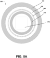
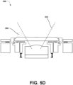
- FIGS 5A-5E illustrates an apparatus 500, according to example embodiments.
- Apparatus 500 can include any components described in Figure 4 .
- camera 502 with lens 504 is disposed within housing 506.
- housing 506 Also included in housing 506 is a sealing surface 508 and a threaded portion 510.
- Retainer ring 530 further includes retaining portion 532 and threaded portion 534. Threaded portion 534 of retainer ring 530 is configured to be coupled with threaded portion 510 of housing 506. Retaining portion 532 of retainer ring 530 is configured to be chamfered such that chamfer 522 of window 520 and the chamfer of retaining portion 532 align and secure window 520 to the sealing surface 508 of housing 506 to form a watertight seal.
- window 520 with chamfer 522 can further include a radiused window edge 524 to further reduce any sharp edges on window 520 along with chamfer 522.
- a front of the window 520 can be higher than a front of the retainer ring 530 by distance 526, as shown in Figure 5E , such that the retainer ring 520 does not extend in front of the front surface of the window 520 when the retaining portion 532 holds the window 520 against the sealing surface 508 of the housing 506.
- apparatus 500 includes a heating module 540.
- Heating module 540 can include window heater ring 542 and springs 544 such that springs 544 bias heater 542 against a back portion of window 520.
- apparatus 500 includes a wiper blade 550.
- Wiper blade 550 can be designed to contact a front portion of window 520.
- apparatus 500 includes an O-ring 560.
- O-ring 560 can be disposed within sealing surface 508 of housing 506 to aid in forming a watertight seal between housing 506 and window 520.
- apparatus 500 includes a window 520 that is partially opaque and partially transparent.
- window 520 could include a transparent portion within region 570 and an opaque portion extending radially outward from region 570.
- the transparent portion within region 570 can correspond to field of view 572 of camera 502 such that camera 502 is able to sense the environment in front of window 520 through the transparent portion within region 570 of window 520.
- Figure 6 illustrates a method 600, according to an example embodiment. While method 600 illustrates block 602, it will be understood that more blocks or steps could be included. Furthermore, blocks or steps may be added and/or repeated. Any components in Figures 4-5E can be included in the embodiment described by method 600.
- Block 602 could include attaching a window to a housing by means of a retainer ring.
- the window can be the chamfered window described in Figures 4-5E .
- the housing further can house a camera with a lens and further includes a sealing surface.
- the chamfered window is configured to provide a protective aperture for the camera lens when a retaining portion of the retainer ring contacts the chamfer of the window and the retainer ring further couples to the housing to hold the window against the sealing surface of the housing to form a watertight seal.
- method 600 further includes a housing that comprises an internally threaded portion, wherein the retainer ring comprises an externally threaded portion, such that the coupling comprises engaging the externally threaded portion of the retainer ring with the internally threaded portion of the housing.
- method 600 further includes a window that comprises a front surface, a back surface opposite the front surface, and a side surface extending between the front surface and the back surface.
- the chamfer is in the side surface and the watertight seal is formed between the back surface of the window and the sealing surface of the housing.
- method 600 further includes a retainer ring that does not extend in front of the front surface of the window when the retaining portion holds the window against the sealing surface of the housing to form the watertight seal.
- method 600 further includes, prior to attaching the window by means of the retainer ring, removing, from the housing, a previous window, wherein the previous window is damaged. This can be done by visual inspection or by a sensor connected to the aperture detecting percentage of damage on the window of the aperture in real-time.
- each step, block, operation, and/or communication can represent a processing of information and/or a transmission of information in accordance with example embodiments.
- Alternative embodiments are included within the scope of these example embodiments.
- operations described as steps, blocks, transmissions, communications, requests, responses, and/or messages can be executed out of order from that shown or discussed, including substantially concurrently or in reverse order, depending on the functionality involved.
- blocks and/or operations can be used with any of the message flow diagrams, scenarios, and flow charts discussed herein, and these message flow diagrams, scenarios, and flow charts can be combined with one another, in part or in whole.
- a step, block, or operation that represents a processing of information can correspond to circuitry that can be configured to perform the specific logical functions of a herein-described method or technique.
- a step or block that represents a processing of information can correspond to a module, a segment, or a portion of program code (including related data).
- the program code can include one or more instructions executable by a processor for implementing specific logical operations or actions in the method or technique.
- the program code and/or related data can be stored on any type of computer-readable medium such as a storage device including RAM, a disk drive, a solid state drive, or another storage medium.
- a step, block, or operation that represents one or more information transmissions can correspond to information transmissions between software and/or hardware modules in the same physical device.
- other information transmissions can be between software modules and/or hardware modules in different physical devices.
Applications Claiming Priority (1)
| Application Number | Priority Date | Filing Date | Title |
|---|---|---|---|
| US17/943,387 US20240085693A1 (en) | 2022-09-13 | 2022-09-13 | Replaceable, Heated, and Wipeable Apertures for Optical Systems |
Publications (1)
| Publication Number | Publication Date |
|---|---|
| EP4339700A1 true EP4339700A1 (fr) | 2024-03-20 |
Family
ID=87972004
Family Applications (1)
| Application Number | Title | Priority Date | Filing Date |
|---|---|---|---|
| EP23195911.5A Pending EP4339700A1 (fr) | 2022-09-13 | 2023-09-07 | Ouvertures remplaçables, chauffées et pouvant être séchées pour systèmes optiques |
Country Status (3)
| Country | Link |
|---|---|
| US (1) | US20240085693A1 (fr) |
| EP (1) | EP4339700A1 (fr) |
| JP (1) | JP2024041048A (fr) |
Citations (6)
| Publication number | Priority date | Publication date | Assignee | Title |
|---|---|---|---|---|
| US4994829A (en) * | 1989-07-10 | 1991-02-19 | Nikon Corporation | Waterproof camera and lens mount therefore |
| US5077567A (en) * | 1990-08-20 | 1991-12-31 | Asahi Kogaku Kogyo Kabushiki Kaisha | Water-sealed camera |
| JP2005017951A (ja) * | 2003-06-27 | 2005-01-20 | Kyocera Corp | 撮像装置 |
| US20060177206A1 (en) * | 2004-11-30 | 2006-08-10 | Olympus Corporation | Waterproof housing |
| US20090244734A1 (en) * | 2008-03-28 | 2009-10-01 | Naoki Sasaki | Lens assembly and imaging apparatus |
| US20190293898A1 (en) * | 2016-03-18 | 2019-09-26 | Sumitomo Electric Industries, Ltd. | Infrared lens unit |
-
2022
- 2022-09-13 US US17/943,387 patent/US20240085693A1/en active Pending
-
2023
- 2023-08-17 JP JP2023132758A patent/JP2024041048A/ja active Pending
- 2023-09-07 EP EP23195911.5A patent/EP4339700A1/fr active Pending
Patent Citations (6)
| Publication number | Priority date | Publication date | Assignee | Title |
|---|---|---|---|---|
| US4994829A (en) * | 1989-07-10 | 1991-02-19 | Nikon Corporation | Waterproof camera and lens mount therefore |
| US5077567A (en) * | 1990-08-20 | 1991-12-31 | Asahi Kogaku Kogyo Kabushiki Kaisha | Water-sealed camera |
| JP2005017951A (ja) * | 2003-06-27 | 2005-01-20 | Kyocera Corp | 撮像装置 |
| US20060177206A1 (en) * | 2004-11-30 | 2006-08-10 | Olympus Corporation | Waterproof housing |
| US20090244734A1 (en) * | 2008-03-28 | 2009-10-01 | Naoki Sasaki | Lens assembly and imaging apparatus |
| US20190293898A1 (en) * | 2016-03-18 | 2019-09-26 | Sumitomo Electric Industries, Ltd. | Infrared lens unit |
Also Published As
| Publication number | Publication date |
|---|---|
| JP2024041048A (ja) | 2024-03-26 |
| US20240085693A1 (en) | 2024-03-14 |
Similar Documents
| Publication | Publication Date | Title |
|---|---|---|
| US11561108B2 (en) | Methods and systems for sun-aware vehicle routing | |
| US20200151468A1 (en) | Methods and Systems for Controlling Extent of Light Encountered by an Image Capture Device of a Self-Driving Vehicle | |
| US11945467B2 (en) | Identification of proxy calibration targets for a fleet of vehicles | |
| US11653108B2 (en) | Adjustable vertical field of view | |
| US20230266440A1 (en) | Sensor Unit with Rotating Housing and Spoiler for Enhanced Airflow | |
| US20220244395A1 (en) | Calibration and Localization of a Light Detection and Ranging (Lidar) Device Using a Previously Calibrated and Localized Lidar Device | |
| EP4339700A1 (fr) | Ouvertures remplaçables, chauffées et pouvant être séchées pour systèmes optiques | |
| US20240106987A1 (en) | Multi-Sensor Assembly with Improved Backward View of a Vehicle | |
| US20240109519A1 (en) | Wiper Devices for Sensor Housings | |
| US20220163675A1 (en) | Methods of Using Background Images from a Light Detection and Ranging (LIDAR) Device | |
| US11781549B1 (en) | Air cooling system for electronic spinning assembly | |
| US20230041448A1 (en) | Pedestrian Countdown Signal Classification to Increase Pedestrian Behavior Legibility | |
| EP4187284A1 (fr) | Utilisation d'une caméra dans un dispositif lidar pour détecter les salissures sur la fenêtre lidar | |
| US20230408651A1 (en) | Spinning Lidar With One or More Secondary Mirrors | |
| US20240085343A1 (en) | Temporally Modulated Light Emission for Defect Detection in Light Detection and Ranging (Lidar) Devices and Cameras |
Legal Events
| Date | Code | Title | Description |
|---|---|---|---|
| PUAI | Public reference made under article 153(3) epc to a published international application that has entered the european phase |
Free format text: ORIGINAL CODE: 0009012 |
|
| STAA | Information on the status of an ep patent application or granted ep patent |
Free format text: STATUS: THE APPLICATION HAS BEEN PUBLISHED |
|
| AK | Designated contracting states |
Kind code of ref document: A1 Designated state(s): AL AT BE BG CH CY CZ DE DK EE ES FI FR GB GR HR HU IE IS IT LI LT LU LV MC ME MK MT NL NO PL PT RO RS SE SI SK SM TR |