EP4339678A1 - Optical system, image projection device, and imaging device - Google Patents
Optical system, image projection device, and imaging device Download PDFInfo
- Publication number
- EP4339678A1 EP4339678A1 EP21942002.3A EP21942002A EP4339678A1 EP 4339678 A1 EP4339678 A1 EP 4339678A1 EP 21942002 A EP21942002 A EP 21942002A EP 4339678 A1 EP4339678 A1 EP 4339678A1
- Authority
- EP
- European Patent Office
- Prior art keywords
- lens group
- optical system
- magnification
- lens
- lens element
- Prior art date
- Legal status (The legal status is an assumption and is not a legal conclusion. Google has not performed a legal analysis and makes no representation as to the accuracy of the status listed.)
- Granted
Links
Images









Classifications
-
- G—PHYSICS
- G02—OPTICS
- G02B—OPTICAL ELEMENTS, SYSTEMS OR APPARATUS
- G02B15/00—Optical objectives with means for varying the magnification
- G02B15/14—Optical objectives with means for varying the magnification by axial movement of one or more lenses or groups of lenses relative to the image plane for continuously varying the equivalent focal length of the objective
- G02B15/143—Optical objectives with means for varying the magnification by axial movement of one or more lenses or groups of lenses relative to the image plane for continuously varying the equivalent focal length of the objective having three groups only
- G02B15/1431—Optical objectives with means for varying the magnification by axial movement of one or more lenses or groups of lenses relative to the image plane for continuously varying the equivalent focal length of the objective having three groups only the first group being positive
- G02B15/143103—Optical objectives with means for varying the magnification by axial movement of one or more lenses or groups of lenses relative to the image plane for continuously varying the equivalent focal length of the objective having three groups only the first group being positive arranged ++-
-
- G—PHYSICS
- G02—OPTICS
- G02B—OPTICAL ELEMENTS, SYSTEMS OR APPARATUS
- G02B13/00—Optical objectives specially designed for the purposes specified below
- G02B13/04—Reversed telephoto objectives
-
- G—PHYSICS
- G02—OPTICS
- G02B—OPTICAL ELEMENTS, SYSTEMS OR APPARATUS
- G02B13/00—Optical objectives specially designed for the purposes specified below
- G02B13/0095—Relay lenses or rod lenses
-
- G—PHYSICS
- G02—OPTICS
- G02B—OPTICAL ELEMENTS, SYSTEMS OR APPARATUS
- G02B13/00—Optical objectives specially designed for the purposes specified below
- G02B13/16—Optical objectives specially designed for the purposes specified below for use in conjunction with image converters or intensifiers, or for use with projectors, e.g. objectives for projection TV
-
- G—PHYSICS
- G02—OPTICS
- G02B—OPTICAL ELEMENTS, SYSTEMS OR APPARATUS
- G02B15/00—Optical objectives with means for varying the magnification
- G02B15/14—Optical objectives with means for varying the magnification by axial movement of one or more lenses or groups of lenses relative to the image plane for continuously varying the equivalent focal length of the objective
- G02B15/144—Optical objectives with means for varying the magnification by axial movement of one or more lenses or groups of lenses relative to the image plane for continuously varying the equivalent focal length of the objective having four groups only
- G02B15/1441—Optical objectives with means for varying the magnification by axial movement of one or more lenses or groups of lenses relative to the image plane for continuously varying the equivalent focal length of the objective having four groups only the first group being positive
- G02B15/144111—Optical objectives with means for varying the magnification by axial movement of one or more lenses or groups of lenses relative to the image plane for continuously varying the equivalent focal length of the objective having four groups only the first group being positive arranged ++-+
-
- G—PHYSICS
- G02—OPTICS
- G02B—OPTICAL ELEMENTS, SYSTEMS OR APPARATUS
- G02B15/00—Optical objectives with means for varying the magnification
- G02B15/14—Optical objectives with means for varying the magnification by axial movement of one or more lenses or groups of lenses relative to the image plane for continuously varying the equivalent focal length of the objective
- G02B15/16—Optical objectives with means for varying the magnification by axial movement of one or more lenses or groups of lenses relative to the image plane for continuously varying the equivalent focal length of the objective with interdependent non-linearly related movements between one lens or lens group, and another lens or lens group
- G02B15/20—Optical objectives with means for varying the magnification by axial movement of one or more lenses or groups of lenses relative to the image plane for continuously varying the equivalent focal length of the objective with interdependent non-linearly related movements between one lens or lens group, and another lens or lens group having an additional movable lens or lens group for varying the objective focal length
-
- G—PHYSICS
- G02—OPTICS
- G02B—OPTICAL ELEMENTS, SYSTEMS OR APPARATUS
- G02B13/00—Optical objectives specially designed for the purposes specified below
- G02B13/18—Optical objectives specially designed for the purposes specified below with lenses having one or more non-spherical faces, e.g. for reducing geometrical aberration
Definitions
- the present disclosure relates to an optical system that forms an intermediate image.
- the present disclosure also relates to an image projection apparatus and an imaging apparatus using such an optical system.
- Patent Document 1 discloses a wide-angle imaging optical system, wherein focus adjustment is preformed using two focus groups located on the magnification side with respect to the intermediate image. Therefore, in this imaging optical system, the center of gravity is positioned on the magnification side of the optical system due to the driving member including actuators that constitute the focus groups. Further, in this imaging optical system, fluctuation of the off-axis curvature of field during focusing reaches about 0.05 mm.
- Patent Document 2 discloses a wide-angle imaging optical system, wherein focus adjustment is preformed using two or three focus groups.
- two focus groups fluctuation of the off-axis-most meridional curvature of field on the closest side and the far side reaches 0.1 mm or more, indicating insufficient optical performances.
- three focus groups fluctuation of the off-axis-most meridional curvature of field on the closest side and the far side is small, indicating good optical performances.
- three focus groups must be moved, thereby increasing the weight of the actuators.
- the present disclosure provides an optical system in which focus adjustment is easy to perform and a focus mechanism can be reduced in size and weight.
- the present disclosure also provides an image projection apparatus and an imaging apparatus using such an optical system.
- An optical system internally having an intermediate imaging position that is conjugate with both of a magnification conjugate point on a magnification side and a reduction conjugate point on a reduction side, the optical system comprising:
- an image projection apparatus includes the above-described optical system and an image forming element that generates an image to be projected through the optical system onto a screen.
- an imaging apparatus includes the above-described optical system and an imaging element that receives an optical image formed by the optical system to convert the optical image into an electrical image signal.
- the present disclosure provides an optical system in which focus adjustment is easy to perform and a focus mechanism can be reduced in size and weight.
- optical system each example of an optical system according to the present disclosure is described below.
- the optical system is used in a projector (an example of an image projection apparatus) that projects onto a screen image light of an original image S obtained by spatially modulating incident light using an image forming element, such as liquid crystal or digital micromirror device (DMD), based on an image signal.
- an image forming element such as liquid crystal or digital micromirror device (DMD)
- the optical system according to the present disclosure can be used for magnifying the original image S on the image forming element arranged on the reduction side to project the image onto the screen (not shown), which is arranged on an extension line on the magnification side.
- optical system according to the present disclosure can also be used for collecting light emitted from an object located on the extension line on the magnification side to form an optical image of the object on an imaging surface of an imaging element arranged on the reduction side.
- a zoom lens system is described as an example of the optical system.
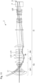
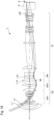
- Figs. 1 , 6 , 11 , 16 , and 21 are layout diagrams each showing an optical path at a wide-angle end in a zoom lens system according to any of examples 1 to 5 for an object distance of 1080 mm.
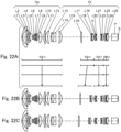
- Figs. 2 , 7 , 12 , 17 , and 22 are layout diagrams of the wide-angle end in the zoom lens systems according to examples 1 to 5 for an object distance of 1080 mm.
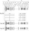
- Figs. 2A , 7A , 12A , 17A , and 22A show lens layout diagrams at the wide-angle end in the zoom lens system.
- Figs. 2B , 7B , 12B , 17B , and 22B show lens layout diagrams at an intermediate position in the zoom lens system.
- Figs. 2C , 7C , 12C , 17C , and 22C show lens layout diagrams at a telephoto end in the zoom lens system.
- the wide-angle end is defined as the shortest focal length state in which the entire optical system has the shortest focal length fw.
- the intermediate position is defined as an intermediate focal length state between the wide-angle end and the telephoto end.
- the telephoto end is defined as the longest focal length state in which the entire optical system has the longest focal length ft.
- the zoom lens systems according to examples 1 to 5 internally include an intermediate imaging position MI that is conjugate with both of a magnification conjugate point on the magnification side and a reduction conjugate point on the reduction side.
- a magnification optical system Op is arranged on the magnification side with respect to the intermediate imaging position MI
- a relay optical system Ol is arranged on the reduction side with respect to the intermediate imaging position MI.
- An optical element P is arranged on the reduction side with respect to the relay optical system Ol.
- the zoom lens systems according to examples 1 to 5 include a first lens group G1 to a fourth lens group G4 that are movable independently of one another.
- the first lens group G1 has a positive power, and is constituted of a first lens element L1 to a 15th lens element L15, including a surface 1 to a surface 30 (for surface numbers, see numerical examples described later).
- the second lens group G2 has a positive power, and is constituted of a 16th lens element L16 to an 18th lens element L18, including a surface 31 to a surface 36.
- the third lens group G3 has a negative power, and is constituted of a 19th lens element L19 to a 22nd lens element L22, including a surface 37 to a surface 45.
- the fourth lens group G4 has a positive power, and is constituted of a 23rd lens element L23 to a 25th lens element L25, including a surface 46 to a surface 51.
- the optical element P includes a surface 52 and a surface 53.
- the polygonal line arrows shown in lower part of each Figs. 2A , 7A , 12A , 17A , and 22A include straight lines obtained by connecting the positions of the first lens group G1 to the fourth lens group G4 corresponding to each of the states of the wide-angle end, the intermediate position, and the telephoto end ranked in order from the top in the drawings.
- the wide-angle end and the intermediate position, and the intermediate position and the telephoto end are simply connected by a straight line, which is different from the actual movement of each of the lens groups G1 to G4.
- the symbols (+) and (-) attached to the reference numerals of the respective lens groups G1 to G4 indicate the positive or negative power of each of the lens groups G1 to G4.
- the zoom lens systems according to examples 1 to 5 may include, as necessary, a focus lens group that performs focus adjustment when an object distance is changed, and a field curvature correction lens group that corrects field curvature aberration after the focus lens group performs focus adjustment.
- the zoom lens systems according to examples 1 to 5 include a first positive lens group GP1 having a positive power, a second positive lens group GP2 having a positive power, and a negative lens group GN having a negative power.
- the first positive lens group GP1 and the negative lens group GN move independently of each other in the optical axis direction, and the second positive lens group GP2 is stationary.
- the first positive lens group GP1 can function as the field curvature correction lens group described above
- the negative lens group GN can function as the focus lens group described above.
- an imaging position on the magnification side i.e., the magnification conjugate point
- an imaging position on the reduction side i.e., the reduction conjugate point
- a straight line drawn closest to the reduction side represents a position of the original image S
- the optical element P is positioned on the magnification side of the original image S.
- the optical element P represents different optical elements, such as a prism for color separation and color synthesis, an optical filter, a flat-parallel glass plate, a crystal low-pass filter, and an infrared cut filter.
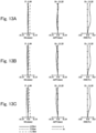
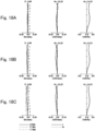
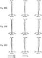
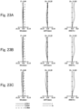
- Figs. 3A-3C , 8A-8C , 13A-13C , 18A-18C , and 23A-23C are longitudinal aberration diagrams of the zoom lens systems according to examples 1 to 5 for an object distance of 1080 mm.
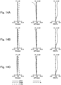
- Figs. 4A-4C , 9A-9C , 14A-14C , 19A-19C , and 24A-24C are longitudinal aberration diagrams of the zoom lens systems according to examples 1 to 5 for an object distance of 780 mm.
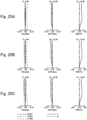
- Figs. 5A-5C , 10A-10C , 15A-15C , 20A-20C , and 25A-25C are longitudinal aberration diagrams of the zoom lens systems according to examples 1 to 5 for an object distance of 2900 mm. In each drawing, Figs.
- 3A to 5A , 8A to 10A , 13A to 15A , 18A to 20A , 23A to 25A show longitudinal aberration diagrams at the wide-angle end of the zoom lens system
- Figs. 3B to 5B , 8B to 10B , 13B to 15B , 18B to 20B , 23B to 25B show longitudinal aberration diagrams at the intermediate position
- Figs. 3C to 5C , 8C to 10C , 13C to 15C , 18C to 20C , 23C to 25C show longitudinal aberration diagrams at the telephoto end.
- Each of the longitudinal aberration diagrams shows spherical aberration (SA (mm)), astigmatism (AST (mm)), and distortion (DIS (%)) in order from the left side.
- the vertical axis represents a pupil height
- the solid line represents the characteristic of the d-line
- the short dashed line represents the characteristic of the F-line
- the long dashed line represents the characteristic of the C-line.
- the vertical axis represents an image height
- the solid line represents the characteristic of the sagittal plane (denoted by s in the drawing)
- the dashed line represents characteristic of the meridional plane (denoted by m in the drawing).
- the vertical axis represents the image height.
- the distortion aberration represents a distortion with respect to equidistant projection.
- the zoom lens system according to example 1 includes the magnification optical system Op and the relay optical system Ol.
- the magnification optical system Op is constituted of the first lens element L1 to the 12th lens element L12 in order from the magnification side to the reduction side.
- the first lens element L1 has a negative meniscus shape with the convex surface facing the magnification side.
- the second lens element L2 has a positive meniscus shape with the convex surface facing the magnification side.
- the third lens element L3 has a negative meniscus shape with the convex surface facing the magnification side.
- the fourth lens element L4 has a negative meniscus shape with the convex surface facing the magnification side.
- the fifth lens element L5 has a biconvex shape.
- the sixth lens element L6 has a positive meniscus shape with the convex surface facing the reduction side.
- the seventh lens element L7 has a biconvex shape.
- the eighth lens element L8 has a biconcave shape.
- the ninth lens element L9 has a positive meniscus shape with the convex surface facing the reduction side.
- the 10th lens element L10 has a biconvex shape.
- the 11th lens element L11 has a biconvex shape.
- the 12th lens element L12 has a positive meniscus shape with the convex surface facing the magnification side.
- the relay optical system Ol is constituted of the 13th lens element L13 to the 25th lens element L25 in order from the magnification side to the reduction side.
- the 13th lens element L13 has a biconcave shape.
- the 14th lens element L14 has a biconcave shape.
- the 15th lens element L15 has a positive meniscus shape with the convex surface facing the reduction side.
- the 16th lens element L16 has a biconvex shape.
- the 17th lens element L17 has a biconcave shape.
- the 18th lens element L18 has a biconvex shape.
- the 19th lens element L19 has a positive meniscus shape with the convex surface facing the magnification side.
- the 20th lens element L20 has a negative meniscus shape with the convex surface facing the magnification side.
- the 21st lens element L21 has a negative meniscus shape with the convex surface facing the reduction side.
- the 22nd lens element L22 has a biconvex shape.
- the 23rd lens element L23 has a biconvex shape.
- the 24th lens element L24 has a negative meniscus shape with the convex surface facing the magnification side.
- the 25th lens element L25 has a biconvex shape.
- the intermediate imaging position MI is positioned between the 12th lens element L12 and the 13th lens element L13.
- An aperture A is arranged between the 19th lens element L19 and the 20th lens element L20.
- the optical element P having zero optical power is arranged on the reduction side of the relay optical system Ol.
- the first positive lens group GP1 is constituted of the first lens element L1 to the ninth lens element L9.
- the second positive lens group GP2 is constituted of the 10th lens element L10 to the 12th lens element L12.
- the negative lens group GN is constituted of the 13th lens element L13 and the 14th lens element L14.
- the zoom lens system according to example 2 includes the magnification optical system Op and the relay optical system Ol.
- the magnification optical system Op is constituted of the first lens element L1 to the 12th lens element L12 in order from the magnification side to the reduction side. Shapes of the first lens element L1 to the ninth lens element L9 and the 12th lens element L12 are similar to those of example 1, and redundant description will be omitted.
- the 10th lens element L10 has a positive meniscus shape with the convex surface facing the reduction side.
- the 11th lens element L11 has a positive meniscus shape with the convex surface facing the magnification side.
- the relay optical system Ol is constituted of the 13th lens element L13 to the 25th lens element L25 in order from the magnification side to the reduction side. These lens shapes are similar to those of example 1, and redundant description will be omitted.
- the intermediate imaging position MI and the arrangement of the aperture A and the optical element P are also similar to those of example 1.
- the first positive lens group GP1 is constituted of the first lens element L1 to the ninth lens element L9.
- the second positive lens group GP2 is constituted of the 10th lens element L10 to the 12th lens element L12.
- the negative lens group GN is constituted of the 13th lens element L13 and the 14th lens element L14.
- the zoom lens system according to example 3 includes the magnification optical system Op and the relay optical system Ol.
- the magnification optical system Op is constituted of the first lens element L1 to the 12th lens element L12 in order from the magnification side to the reduction side.
- the relay optical system Ol is constituted of the 13th lens element L13 to the 25th lens element L25 in order from the magnification side to the reduction side.
- the first positive lens group GP1 is constituted of the first lens element L1 to the ninth lens element L9.
- the second positive lens group GP2 is constituted of the 10th lens element L10 to the 12th lens element L12.
- the negative lens group GN is constituted of the 13th lens element L13 and the 14th lens element L14.
- the zoom lens system according to example 4 includes the magnification optical system Op and the relay optical system Ol.
- the magnification optical system Op is constituted of the first lens element L1 to the 12th lens element L12 in order from the magnification side to the reduction side.
- the relay optical system Ol is constituted of the 13th lens element L13 to the 25th lens element L25 in order from the magnification side to the reduction side.
- the first positive lens group GP1 is constituted of the second lens element L2 to the ninth lens element L9.
- the second positive lens group GP2 is constituted of the 10th lens element L10 to the 12th lens element L12.
- the negative lens group GN is constituted of the 13th lens element L13 and the 14th lens element L14.
- the first lens element L1 is stationary during focusing.
- the zoom lens system according to example 5 includes the magnification optical system Op and the relay optical system Ol.
- the magnification optical system Op is constituted of the first lens element L1 to the 12th lens element L12 in order from the magnification side to the reduction side.
- the relay optical system Ol is constituted of the 13th lens element L13 to the 25th lens element L25 in order from the magnification side to the reduction side.
- the 13th lens element L13 has a negative meniscus shape with the convex surface facing the magnification side.
- Shapes of the 14th lens element L14 to the 25th lens element L25 are similar to those of example 1, and redundant description will be omitted.
- the intermediate imaging position MI and the arrangement of the aperture A and the optical element P are also similar to those of example 1.
- the first positive lens group GP1 is constituted of the first lens element L1 to the ninth lens element L9.
- the second positive lens group GP2 is constituted of the 10th lens element L10 to the 12th lens element L12.
- the negative lens group GN is constituted of the 14th lens element L14.
- the 13th lens element L13 is stationary during focusing.
- the zoom lens system according to each of examples 1 to 5 is an optical system internally having an intermediate imaging position MI that is conjugate with both of a magnification conjugate point on a magnification side and a reduction conjugate point on a reduction side.
- the optical system includes: a first positive lens group GP1 including a plurality of lens elements and positioned on the magnification side with respect to the intermediate imaging position; a second positive lens group GP2 including a plurality of lens elements and positioned between the first positive lens group GP1 and the intermediate imaging position M1; and a negative lens group GN including a plurality of lens elements and positioned on the reduction side with respect to the intermediate imaging position MI.
- the first positive lens group GP1 and the negative lens group GN move in an optical axis direction
- the second positive lens group GP2 is stationary.
- the first positive lens group indicates a smaller change in back focus and a larger change in field curvature due to movement.
- the negative lens group indicates a smaller change in field curvature and a larger change in back focus due to movement, and therefore focus adjustment becomes easier to perform.
- the negative lens group can have a small lens diameter, and therefore the focus configuration can be reduced in size and weight.
- the zoom lens system according to each of examples 1 to 5 may satisfy the following condition (1): 0.10 ⁇ ⁇ p 2 ⁇ 0.35 where ⁇ p2 is a lateral magnification of the second positive lens group GP2.
- condition (1) back focus fluctuation can be reduced when the first positive lens group moves, correction for field curvature generated by the first positive lens group becomes easier to perform, and focus adjustment becomes easier to perform. If exceeding the upper limit of the condition (1), back focus fluctuation of the first positive lens group increases. On the other hand, if falling below the lower limit of the condition (1), larger astigmatism is generated when focus adjustment is performed.
- condition (1) more advantageous effects can be obtained by further satisfying the following condition (1A): 0.21 ⁇ ⁇ p 2 ⁇ 0.25
- the zoom lens system according to each of examples 1 to 5 may satisfy the following condition (2): 0.2 ⁇ ⁇ n ⁇ 1.0 where ⁇ n is a lateral magnification of the negative lens group GN.
- condition (2) back focus fluctuation is increased when the negative lens group moves, and focus adjustment becomes easier to perform. If exceeding the upper limit of the condition (2), aberration due to eccentricity made during manufacturing is increased. On the other hand, if falling below the lower limit of the condition (2), sensitivity of back focus during focus adjustment is decreased, and field curvature becomes relatively likely to occur.
- the zoom lens system according to each of examples 1 to 5 may satisfy the following condition (3): ⁇ 0.2 ⁇ ⁇ p 1 ⁇ 0.0 where ⁇ p1 is a lateral magnification of the first positive lens group GP1.
- back focus fluctuation can be reduced when the first positive lens group moves, correction for field curvature generated by the first positive lens group becomes easier to perform, and focus adjustment becomes easier to perform. If exceeding the upper limit of the condition (3), back focus fluctuation of the first positive lens group increases. On the other hand, even if falling below the lower limit of the condition (3), back focus fluctuation of the first positive lens group also increases.
- the zoom lens system according to each of examples 1 to 5 may satisfy the following condition (4): 2.0 ⁇ fp 1 / fo ⁇ 10.0 where fp1 is a focal length of the first positive lens group GP1, and fo is a focal length of the entire magnification optical system Op positioned on a magnification side with respect to the intermediate imaging position MI.
- the condition (4) is a conditional expression for defining the relationship between the focal length of the first positive lens group and the focal length of the entire magnification optical system positioned on the magnification side with respect to the intermediate imaging position.
- condition (4) In addition to the condition (4), more advantageous effects can be obtained by further satisfying the following condition (4A): 3.5 ⁇ fp 1 / fo ⁇ 5.0
- the zoom lens system according to each of examples 1 to 5 may satisfy the following condition (5): ⁇ 5.0 ⁇ fn / fo ⁇ ⁇ 1.0 where fn is a focal length of the negative lens group GN, and fo is a focal length of the entire magnification optical system Op positioned on the magnification side with respect to the intermediate imaging position MI.
- the condition (5) is a conditional expression for defining the relationship between the focal length of the negative lens group and the focal length of the entire magnification optical system positioned on the magnification side with respect to the intermediate imaging position.
- condition (5) more advantageous effects can be obtained by further satisfying the following condition (5A): ⁇ 2.0 ⁇ fn / fo ⁇ ⁇ 1.4
- a magnification side-closest lens element positioned closest to the magnification side of the second positive lens group GP2 may have a positive power and satisfy the following condition (6): ⁇ 1.40 ⁇ R 2 + R 1 / R 2 ⁇ R 1 ⁇ ⁇ 0.70 where R1 is a radius of curvature of the surface on the magnification side of the magnification side-closest lens element, and R2 is a radius of curvature of the surface on the reduction side of the magnification side-closest lens element.
- the condition (6) is a conditional expression for defining the relationship between the radii of curvature of the surface on the magnification side and the radius of curvature of the surface on the reduction side of the magnification side-closest lens element.
- the magnification side-closest lens element positioned closest to the magnification side of the second positive lens group GP2 may be the 10th lens element L10 having a biconvex shape or a positive meniscus shape with the convex surface facing the reduction side.
- the zoom lens system according to each of examples 1 to 5 may further include an adjacent lens element adjacent to the reduction side of the negative lens group GN and having a positive power, and satisfing the following condition (7): npd > 1.85 where npd is a refractive index of the adjacent lens element.
- the adjacent lens element may be the 15th lens element L15 having a positive meniscus shape with the convex surface facing the reduction side.
- the zoom lens system according to each of examples 1 to 5 may further include an adjacent lens element adjacent to the reduction side of the negative lens group GN and having a positive power, and satisfing the following condition (8): 25 ⁇ vpd ⁇ 30 where vpd is an Abbe number of the adjacent lens element.
- the negative lens group GN may include the lens element positioned closest to the magnification side among the plurality of lens elements positioned on the reduction side with respect to the intermediate imaging position MI.
- the negative lens group GN may include the 13th lens element L13 positioned closest to the magnification side among the plurality of lens elements L13 to L25 positioned on the reduction side with respect to the intermediate imaging position MI.
- the negative lens group GN may be constituted of two lens elements each having a biconcave shape.
- back focus fluctuation can be increased when the negative lens group moves, and occurrence of the field curvature can be reduced.
- This enables division of roles of focus adjustment, and therefore focus adjustment becomes easier to perform.
- the negative lens group GN may be constituted of the 13th lens element L13 having a biconcave shape and the 14th lens element L14 having a biconcave shape.
- the first positive lens group GP1 may include the lens element positioned closest to the magnification side among the plurality of lens elements positioned on the magnification side with respect to the intermediate imaging position MI.
- the configuration of a focus mechanism member can be simplified.
- the first positive lens group GP1 may include the first lens element L1 positioned closest to the magnification side among the plurality of lens elements L1 to L12 positioned on the magnification side with respect to the intermediate imaging position MI.
- r is a radius of curvature
- d is a surface interval
- nd is a refractive index for d line
- vd is an Abbe number for d line.
- a surface marked with "*" is aspherical, and the aspherical shape is defined by the following formula.
- Z h 2 / r 1 + 1 ⁇ 1 ⁇ ⁇ h / r 2 + ⁇ A n h n
- Z is a distance from a point located on an aspherical surface at a height "h" from the optical axis, to the tangent plane of the aspherical vertex
- h is a height from the optical axis
- r is a radius of curvature of the vertex
- ⁇ is a cone constant
- An is a nth-order aspherical coefficient.
- Table 1 shows surface data
- Table 2 shows various data
- Table 3 shows focus data
- Table 4 shows single lens data
- Table 5 shows zoom lens group data
- Table 6 shows zoom lens group magnification ratios (unit: mm).
- Table 7 shows surface data
- Table 8 shows various data
- Table 9 shows focus data
- Table 10 shows single lens data
- Table 11 shows zoom lens group data
- Table 12 shows zoom lens group magnification ratios (unit: mm).
- Table 13 shows surface data
- Table 14 shows various data
- Table 15 shows focus data
- Table 16 shows single lens data
- Table 17 shows zoom lens group data
- Table 18 shows zoom lens group magnification ratios (unit: mm).
- Table 19 shows surface data
- Table 20 shows various data
- Table 21 shows focus data
- Table 22 shows single lens data
- Table 23 shows zoom lens group data
- Table 24 shows zoom lens group magnification ratios (unit: mm).
- Table 25 shows surface data
- Table 26 shows various data
- Table 27 shows focus data
- Table 28 shows single lens data
- Table 29 shows zoom lens group data
- Table 30 shows zoom lens group magnification ratios (unit: mm).
- Table 31 shows the corresponding values of the respective conditional expressions (1) to (8) in the respective numerical examples.
- Condition Ex. 1 Ex. 2 Ex. 3 Ex. 4 Ex. 5 (1) ⁇ p2 0.236 0.214 0.244 0.235 0.243 (2) ⁇ n 0.554 0.563 0.544 0.566 0.628 (3) ⁇ 1 -0.041 -0.045 -0.041 -0.119 -0.041 (4) fp1/fo 4.17 4.60 4.04 4.43 4.05 (5) fn/fo -1.67 -1.69 -1.63 -1.71 -3.20 (6) (R2+R1)/ -0.867 -1.013 -0.844 -0.900 -0.955 (R2-R1) (7) npd 1.85451 1.85451 1.85451 1.85451 1.85451 1.85451 (8) vpd 25.2 25.2 25.2 25.2 25.2 25.2 25.2 25.2 25.2 25.2 25.2 25.2 25.2 25.2 25.2 25.2 25.2 25.2
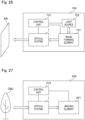
- Fig. 26 is a block diagram showing an example of the image projection apparatus according to the present disclosure.
- the image projection apparatus 100 includes such an optical system 1 as disclosed in the first embodiment, an image forming element 101, a light source 102, a control unit 110, and others.
- the image forming element 101 is constituted of, for example, liquid crystal or DMD, for generating an image to be projected through the optical system 1 onto a screen SR.
- the light source 102 is constituted of such as a light emitting diode (LED) or a laser, and supplies light to the image forming element 101.
- LED light emitting diode
- the control unit 110 is constituted of, for example, central processing unit (CPU) or micro-processing unit (MPU), for controlling the entire apparatus and respective components.
- the optical system 1 may be configured as an interchangeable lens that can be detachably attached to the image projection apparatus 100.
- an apparatus in which the optical system 1 is removed from the image projection apparatus 100 is an example of a main body apparatus.
- the image projection apparatus 100 described above can realize a wide-angle zoom function while achieving reduction in size and weight of the apparatus by employing the optical system 1 according to the first embodiment.
- Fig. 27 is a block diagram showing an example of the imaging apparatus according to the present disclosure.
- the imaging apparatus 200 includes such an optical system 1 as disclosed in the first embodiment, an imaging element 201, a control unit 210, and others.
- the imaging element 201 is constituted of, for example, charge coupled device (CCD) image sensor or complementary metal oxide semiconductor (CMOS) image sensor, for receiving an optical image of an object OBJ formed by the optical system 1 to convert the image into an electrical image signal.
- the control unit 110 is constituted of, for example, CPU or MPU, for controlling the entire apparatus and respective components.
- the optical system 1 may be configured as an interchangeable lens that can be detachably attached to the imaging apparatus 200. In this case, an apparatus in which the optical system 1 is removed from the imaging apparatus 200 is an example of a main body apparatus.
- the imaging apparatus 200 described above can realize a wide-angle zoom function while achieving reduction in size and weight of the apparatus by employing the optical system 1 according to the first embodiment.
- the present disclosure can be applied to image projection apparatuses such as projectors and head-up displays, and imaging apparatuses such as digital still cameras, digital video cameras, surveillance cameras in surveillance systems, web cameras, and onboard cameras.
- imaging apparatuses such as digital still cameras, digital video cameras, surveillance cameras in surveillance systems, web cameras, and onboard cameras.
- the present disclosure can be applied to optical systems that require a high image quality, such as projectors, digital still camera systems, and digital video camera systems.
Landscapes
- Physics & Mathematics (AREA)
- General Physics & Mathematics (AREA)
- Optics & Photonics (AREA)
- Nonlinear Science (AREA)
- Lenses (AREA)
Abstract
Description
- The present disclosure relates to an optical system that forms an intermediate image. The present disclosure also relates to an image projection apparatus and an imaging apparatus using such an optical system.
- Intermediate imaging-based optical systems have an advantage of achieving wide-angle projection with a short focal length and a wide screen. However, as the field of view is wider-angle, aberration fluctuation, such as field curvature aberration, astigmatism, etc., becomes larger during focus adjustment for an object distance, thereby possibly degrading the optical performance.
-
Patent Document 1 discloses a wide-angle imaging optical system, wherein focus adjustment is preformed using two focus groups located on the magnification side with respect to the intermediate image. Therefore, in this imaging optical system, the center of gravity is positioned on the magnification side of the optical system due to the driving member including actuators that constitute the focus groups. Further, in this imaging optical system, fluctuation of the off-axis curvature of field during focusing reaches about 0.05 mm. -
Patent Document 2 discloses a wide-angle imaging optical system, wherein focus adjustment is preformed using two or three focus groups. In case of using two focus groups, fluctuation of the off-axis-most meridional curvature of field on the closest side and the far side reaches 0.1 mm or more, indicating insufficient optical performances. In case of using three focus groups, fluctuation of the off-axis-most meridional curvature of field on the closest side and the far side is small, indicating good optical performances. But three focus groups must be moved, thereby increasing the weight of the actuators. -
- [Patent Document 1]
JP 2018-97046 A - [Patent Document 2]
JP 2019-132904 A - The present disclosure provides an optical system in which focus adjustment is easy to perform and a focus mechanism can be reduced in size and weight. The present disclosure also provides an image projection apparatus and an imaging apparatus using such an optical system.
- An optical system according to the present disclosure internally having an intermediate imaging position that is conjugate with both of a magnification conjugate point on a magnification side and a reduction conjugate point on a reduction side, the optical system comprising:
- a first positive lens group including a plurality of lens elements and positioned on the magnification side with respect to the intermediate imaging position;
- a second positive lens group including a plurality of lens elements and positioned between the first positive lens group and the intermediate imaging position; and
- a negative lens group including a plurality of lens elements and positioned on the reduction side with respect to the intermediate imaging position,
- wherein, during focusing, the first positive lens group and the negative lens group move in an optical axis direction, and the second positive lens group is stationary.
- Further, an image projection apparatus according to the present disclosure includes the above-described optical system and an image forming element that generates an image to be projected through the optical system onto a screen.
- Still further, an imaging apparatus according to the present disclosure includes the above-described optical system and an imaging element that receives an optical image formed by the optical system to convert the optical image into an electrical image signal.
- The present disclosure provides an optical system in which focus adjustment is easy to perform and a focus mechanism can be reduced in size and weight.
-
-
Fig. 1 is a layout diagram showing an optical path at a wide-angle end in a zoom lens system of example 1 for an object distance of 1080 mm. -
Figs. 2A-2C are layout diagrams of the zoom lens system according to example 1 for an object distance of 1080 mm. -
Figs. 3A-3C are longitudinal aberration diagrams of the zoom lens system according to example 1 for an object distance of 1080 mm. -
Figs. 4A-4C are longitudinal aberration diagrams of the zoom lens system according to example 1 for an object distance of 780 mm. -
Figs. 5A-5C are longitudinal aberration diagrams of the zoom lens system according to example 1 for an object distance of 2900 mm. -
Fig. 6 is a layout diagram showing an optical path at a wide-angle end in a zoom lens system of example 2 for an object distance of 1080 mm. -
Figs. 7A-7C are layout diagrams of the zoom lens system according to example 2 for an object distance of 1080 mm. -
Figs. 8A-8C are longitudinal aberration diagrams of the zoom lens system according to example 2 for an object distance of 1080 mm. -
Figs. 9A-9C are longitudinal aberration diagrams of the zoom lens system according to example 2 for an object distance of 780 mm. -
Figs. 10A-10C are longitudinal aberration diagrams of the zoom lens system according to example 2 for an object distance of 2900 mm. -
Fig. 11 is a layout diagram showing an optical path at a wide-angle end in a zoom lens system of example 3 for an object distance of 1080 mm. -
Figs. 12A-12C are layout diagrams of the zoom lens system according to example 3 for an object distance of 1080 mm. -
Figs. 13A-13C are longitudinal aberration diagrams of the zoom lens system according to example 3 for an object distance of 1080 mm. -
Figs. 14A-14C are longitudinal aberration diagrams of the zoom lens system according to example 3 for an object distance of 780 mm. -
Figs. 15A-15C are longitudinal aberration diagrams of the zoom lens system according to example 3 for an object distance of 2900 mm. -
Fig. 16 is a layout diagram showing an optical path at a wide-angle end in a zoom lens system of example 4 for an object distance of 1080 mm. -
Figs. 17A-17C are layout diagrams of the zoom lens system according to example 4 for an object distance of 1080 mm. -
Figs. 18A-18C are longitudinal aberration diagrams of the zoom lens system according to example 4 for an object distance of 1080 mm. -
Figs. 19A-19C are longitudinal aberration diagrams of the zoom lens system according to example 4 for an object distance of 780 mm. -
Figs. 20A-20C are longitudinal aberration diagrams of the zoom lens system according to example 4 for an object distance of 2900 mm. -
Fig. 21 is a layout diagram showing an optical path at a wide-angle end in a zoom lens system of example 5 for an object distance of 1080 mm. -
Figs. 22A-22C are layout diagrams of the zoom lens system according to example 5 for an object distance of 1080 mm. -
Figs. 23A-23C are longitudinal aberration diagrams of the zoom lens system according to example 5 for an object distance of 1080 mm. -
Figs. 24A-24C are longitudinal aberration diagrams of the zoom lens system according to example 5 for an object distance of 780 mm. -
Figs. 25A-25C are longitudinal aberration diagrams of the zoom lens system according to example 5 for an object distance of 2900 mm. -
FIG. 26 is a block diagram showing an example of an image projection apparatus according to the present disclosure. -
FIG. 27 is a block diagram showing an example of an imaging apparatus according to the present disclosure. - Hereinafter, embodiments are described in detail with reference to the drawings as appropriate. However, unnecessarily detailed descriptions may be omitted. For example, detailed descriptions of well-known items or redundant descriptions of substantially the same configurations may be omitted. This is to prevent the following description from being unnecessarily redundant and to facilitate understanding by those skilled in the art.
- It should be noted that the applicant provides the accompanying drawings and the following description for those skilled in the art to fully understand the present disclosure, and it is not intended to limit the subject matter described in the claims thereby.
- Each example of an optical system according to the present disclosure is described below. In each example, described is an example in which the optical system is used in a projector (an example of an image projection apparatus) that projects onto a screen image light of an original image S obtained by spatially modulating incident light using an image forming element, such as liquid crystal or digital micromirror device (DMD), based on an image signal. In other words, the optical system according to the present disclosure can be used for magnifying the original image S on the image forming element arranged on the reduction side to project the image onto the screen (not shown), which is arranged on an extension line on the magnification side.
- Further, the optical system according to the present disclosure can also be used for collecting light emitted from an object located on the extension line on the magnification side to form an optical image of the object on an imaging surface of an imaging element arranged on the reduction side.
- Hereinafter, a first embodiment of the present disclosure is described with reference to
Figs. 1 to 25 . Here, a zoom lens system is described as an example of the optical system. -
Figs. 1 ,6 ,11 ,16 , and21 are layout diagrams each showing an optical path at a wide-angle end in a zoom lens system according to any of examples 1 to 5 for an object distance of 1080 mm.Figs. 2 ,7 ,12 ,17 , and22 are layout diagrams of the wide-angle end in the zoom lens systems according to examples 1 to 5 for an object distance of 1080 mm.Figs. 2A ,7A ,12A ,17A , and22A show lens layout diagrams at the wide-angle end in the zoom lens system.Figs. 2B ,7B ,12B ,17B , and22B show lens layout diagrams at an intermediate position in the zoom lens system.Figs. 2C ,7C ,12C ,17C , and22C show lens layout diagrams at a telephoto end in the zoom lens system. - The wide-angle end is defined as the shortest focal length state in which the entire optical system has the shortest focal length fw. The intermediate position is defined as an intermediate focal length state between the wide-angle end and the telephoto end. The telephoto end is defined as the longest focal length state in which the entire optical system has the longest focal length ft. By using the focal length fw at the wide-angle end and the focal length ft at the telephoto end, the focal length fm at the intermediate position can be defined as fm = √(fw × ft) (√: square root).
- The zoom lens systems according to examples 1 to 5 internally include an intermediate imaging position MI that is conjugate with both of a magnification conjugate point on the magnification side and a reduction conjugate point on the reduction side. A magnification optical system Op is arranged on the magnification side with respect to the intermediate imaging position MI, and a relay optical system Ol is arranged on the reduction side with respect to the intermediate imaging position MI. An optical element P is arranged on the reduction side with respect to the relay optical system Ol.
- Regarding the zooming function, the zoom lens systems according to examples 1 to 5 include a first lens group G1 to a fourth lens group G4 that are movable independently of one another. By way of example, the first lens group G1 has a positive power, and is constituted of a first lens element L1 to a 15th lens element L15, including a
surface 1 to a surface 30 (for surface numbers, see numerical examples described later). The second lens group G2 has a positive power, and is constituted of a 16th lens element L16 to an 18th lens element L18, including a surface 31 to a surface 36. The third lens group G3 has a negative power, and is constituted of a 19th lens element L19 to a 22nd lens element L22, including a surface 37 to a surface 45. The fourth lens group G4 has a positive power, and is constituted of a 23rd lens element L23 to a 25th lens element L25, including a surface 46 to a surface 51. The optical element P includes a surface 52 and a surface 53. - The polygonal line arrows shown in lower part of each
Figs. 2A ,7A ,12A ,17A , and22A include straight lines obtained by connecting the positions of the first lens group G1 to the fourth lens group G4 corresponding to each of the states of the wide-angle end, the intermediate position, and the telephoto end ranked in order from the top in the drawings. The wide-angle end and the intermediate position, and the intermediate position and the telephoto end are simply connected by a straight line, which is different from the actual movement of each of the lens groups G1 to G4. The symbols (+) and (-) attached to the reference numerals of the respective lens groups G1 to G4 indicate the positive or negative power of each of the lens groups G1 to G4. - Regarding the focus function, the zoom lens systems according to examples 1 to 5 may include, as necessary, a focus lens group that performs focus adjustment when an object distance is changed, and a field curvature correction lens group that corrects field curvature aberration after the focus lens group performs focus adjustment.
- By way of example, the zoom lens systems according to examples 1 to 5 include a first positive lens group GP1 having a positive power, a second positive lens group GP2 having a positive power, and a negative lens group GN having a negative power. During focusing, the first positive lens group GP1 and the negative lens group GN move independently of each other in the optical axis direction, and the second positive lens group GP2 is stationary. At this time, the first positive lens group GP1 can function as the field curvature correction lens group described above, and the negative lens group GN can function as the focus lens group described above.
- In each of the drawing, an imaging position on the magnification side (i.e., the magnification conjugate point) is positioned on the left side, and an imaging position on the reduction side (i.e., the reduction conjugate point) is positioned on the right side. In each of the drawing, a straight line drawn closest to the reduction side represents a position of the original image S, and the optical element P is positioned on the magnification side of the original image S. The optical element P represents different optical elements, such as a prism for color separation and color synthesis, an optical filter, a flat-parallel glass plate, a crystal low-pass filter, and an infrared cut filter.
-
Figs. 3A-3C ,8A-8C ,13A-13C ,18A-18C , and23A-23C are longitudinal aberration diagrams of the zoom lens systems according to examples 1 to 5 for an object distance of 1080 mm.Figs. 4A-4C ,9A-9C ,14A-14C ,19A-19C , and24A-24C are longitudinal aberration diagrams of the zoom lens systems according to examples 1 to 5 for an object distance of 780 mm.Figs. 5A-5C ,10A-10C ,15A-15C ,20A-20C , and25A-25C are longitudinal aberration diagrams of the zoom lens systems according to examples 1 to 5 for an object distance of 2900 mm. In each drawing,Figs. 3A to 5A ,8A to 10A ,13A to 15A ,18A to 20A ,23A to 25A show longitudinal aberration diagrams at the wide-angle end of the zoom lens system,Figs. 3B to 5B ,8B to 10B ,13B to 15B ,18B to 20B ,23B to 25B show longitudinal aberration diagrams at the intermediate position, andFigs. 3C to 5C ,8C to 10C ,13C to 15C ,18C to 20C ,23C to 25C show longitudinal aberration diagrams at the telephoto end. - Each of the longitudinal aberration diagrams shows spherical aberration (SA (mm)), astigmatism (AST (mm)), and distortion (DIS (%)) in order from the left side. In the spherical aberration diagram, the vertical axis represents a pupil height, the solid line represents the characteristic of the d-line, the short dashed line represents the characteristic of the F-line, and the long dashed line represents the characteristic of the C-line. In the astigmatism diagram, the vertical axis represents an image height, and the solid line represents the characteristic of the sagittal plane (denoted by s in the drawing), and the dashed line represents characteristic of the meridional plane (denoted by m in the drawing). In the distortion diagram, the vertical axis represents the image height. The distortion aberration represents a distortion with respect to equidistant projection.
- As shown in
Figs. 1 and2A-2C , the zoom lens system according to example 1 includes the magnification optical system Op and the relay optical system Ol. The magnification optical system Op is constituted of the first lens element L1 to the 12th lens element L12 in order from the magnification side to the reduction side. The first lens element L1 has a negative meniscus shape with the convex surface facing the magnification side. The second lens element L2 has a positive meniscus shape with the convex surface facing the magnification side. The third lens element L3 has a negative meniscus shape with the convex surface facing the magnification side. The fourth lens element L4 has a negative meniscus shape with the convex surface facing the magnification side. The fifth lens element L5 has a biconvex shape. The sixth lens element L6 has a positive meniscus shape with the convex surface facing the reduction side. The seventh lens element L7 has a biconvex shape. The eighth lens element L8 has a biconcave shape. The ninth lens element L9 has a positive meniscus shape with the convex surface facing the reduction side. The 10th lens element L10 has a biconvex shape. The 11th lens element L11 has a biconvex shape. The 12th lens element L12 has a positive meniscus shape with the convex surface facing the magnification side. - The relay optical system Ol is constituted of the 13th lens element L13 to the 25th lens element L25 in order from the magnification side to the reduction side. The 13th lens element L13 has a biconcave shape. The 14th lens element L14 has a biconcave shape. The 15th lens element L15 has a positive meniscus shape with the convex surface facing the reduction side. The 16th lens element L16 has a biconvex shape. The 17th lens element L17 has a biconcave shape. The 18th lens element L18 has a biconvex shape. The 19th lens element L19 has a positive meniscus shape with the convex surface facing the magnification side. The 20th lens element L20 has a negative meniscus shape with the convex surface facing the magnification side. The 21st lens element L21 has a negative meniscus shape with the convex surface facing the reduction side. The 22nd lens element L22 has a biconvex shape. The 23rd lens element L23 has a biconvex shape. The 24th lens element L24 has a negative meniscus shape with the convex surface facing the magnification side. The 25th lens element L25 has a biconvex shape.
- The intermediate imaging position MI is positioned between the 12th lens element L12 and the 13th lens element L13. An aperture A is arranged between the 19th lens element L19 and the 20th lens element L20. The optical element P having zero optical power is arranged on the reduction side of the relay optical system Ol.
- Regarding the focus function, the first positive lens group GP1 is constituted of the first lens element L1 to the ninth lens element L9. The second positive lens group GP2 is constituted of the 10th lens element L10 to the 12th lens element L12. The negative lens group GN is constituted of the 13th lens element L13 and the 14th lens element L14.
- As shown in
Figs. 6 and7A-7C , the zoom lens system according to example 2 includes the magnification optical system Op and the relay optical system Ol. The magnification optical system Op is constituted of the first lens element L1 to the 12th lens element L12 in order from the magnification side to the reduction side. Shapes of the first lens element L1 to the ninth lens element L9 and the 12th lens element L12 are similar to those of example 1, and redundant description will be omitted. The 10th lens element L10 has a positive meniscus shape with the convex surface facing the reduction side. The 11th lens element L11 has a positive meniscus shape with the convex surface facing the magnification side. - The relay optical system Ol is constituted of the 13th lens element L13 to the 25th lens element L25 in order from the magnification side to the reduction side. These lens shapes are similar to those of example 1, and redundant description will be omitted. The intermediate imaging position MI and the arrangement of the aperture A and the optical element P are also similar to those of example 1.
- Regarding the focus function, the first positive lens group GP1 is constituted of the first lens element L1 to the ninth lens element L9. The second positive lens group GP2 is constituted of the 10th lens element L10 to the 12th lens element L12. The negative lens group GN is constituted of the 13th lens element L13 and the 14th lens element L14.
- As shown in
Figs. 11 and12A-12C , the zoom lens system according to example 3 includes the magnification optical system Op and the relay optical system Ol. The magnification optical system Op is constituted of the first lens element L1 to the 12th lens element L12 in order from the magnification side to the reduction side. The relay optical system Ol is constituted of the 13th lens element L13 to the 25th lens element L25 in order from the magnification side to the reduction side. These lens shapes are similar to those of example 1, and redundant description will be omitted. The intermediate imaging position MI and the arrangement of the aperture A and the optical element P are also similar to those of example 1. - Regarding the focus function, the first positive lens group GP1 is constituted of the first lens element L1 to the ninth lens element L9. The second positive lens group GP2 is constituted of the 10th lens element L10 to the 12th lens element L12. The negative lens group GN is constituted of the 13th lens element L13 and the 14th lens element L14.
- As shown in
Figs. 16 and17A-17C , the zoom lens system according to example 4 includes the magnification optical system Op and the relay optical system Ol. The magnification optical system Op is constituted of the first lens element L1 to the 12th lens element L12 in order from the magnification side to the reduction side. The relay optical system Ol is constituted of the 13th lens element L13 to the 25th lens element L25 in order from the magnification side to the reduction side. These lens shapes are similar to those of example 1, and redundant description will be omitted. The intermediate imaging position MI and the arrangement of the aperture A and the optical element P are also similar to those of example 1. - Regarding the focus function, the first positive lens group GP1 is constituted of the second lens element L2 to the ninth lens element L9. The second positive lens group GP2 is constituted of the 10th lens element L10 to the 12th lens element L12. The negative lens group GN is constituted of the 13th lens element L13 and the 14th lens element L14. The first lens element L1 is stationary during focusing.
- As shown in
Figs. 21 and22A-22C , the zoom lens system according to example 5 includes the magnification optical system Op and the relay optical system Ol. The magnification optical system Op is constituted of the first lens element L1 to the 12th lens element L12 in order from the magnification side to the reduction side. These lens shapes are similar to those of example 1, and redundant description will be omitted. - The relay optical system Ol is constituted of the 13th lens element L13 to the 25th lens element L25 in order from the magnification side to the reduction side. The 13th lens element L13 has a negative meniscus shape with the convex surface facing the magnification side. Shapes of the 14th lens element L14 to the 25th lens element L25 are similar to those of example 1, and redundant description will be omitted. The intermediate imaging position MI and the arrangement of the aperture A and the optical element P are also similar to those of example 1.
- Regarding the focus function, the first positive lens group GP1 is constituted of the first lens element L1 to the ninth lens element L9. The second positive lens group GP2 is constituted of the 10th lens element L10 to the 12th lens element L12. The negative lens group GN is constituted of the 14th lens element L14. The 13th lens element L13 is stationary during focusing.
- Next, conditions which the zoom lens system according to each of examples 1 to 5 can satisfy are described below. Although a plurality of the conditions are defined for the zoom lens system according to each of the examples, all of these plurality of conditions may be satisfied, or the individual conditions may be satisfied to obtain the corresponding effects.
- The zoom lens system according to each of examples 1 to 5 is an optical system internally having an intermediate imaging position MI that is conjugate with both of a magnification conjugate point on a magnification side and a reduction conjugate point on a reduction side. The optical system includes: a first positive lens group GP1 including a plurality of lens elements and positioned on the magnification side with respect to the intermediate imaging position; a second positive lens group GP2 including a plurality of lens elements and positioned between the first positive lens group GP1 and the intermediate imaging position M1; and a negative lens group GN including a plurality of lens elements and positioned on the reduction side with respect to the intermediate imaging position MI. During focusing, the first positive lens group GP1 and the negative lens group GN move in an optical axis direction, and the second positive lens group GP2 is stationary.
- According to such configuration, the first positive lens group indicates a smaller change in back focus and a larger change in field curvature due to movement. The negative lens group indicates a smaller change in field curvature and a larger change in back focus due to movement, and therefore focus adjustment becomes easier to perform. The negative lens group can have a small lens diameter, and therefore the focus configuration can be reduced in size and weight.
- Further, the zoom lens system according to each of examples 1 to 5 may satisfy the following condition (1):

- By satisfying the condition (1), back focus fluctuation can be reduced when the first positive lens group moves, correction for field curvature generated by the first positive lens group becomes easier to perform, and focus adjustment becomes easier to perform. If exceeding the upper limit of the condition (1), back focus fluctuation of the first positive lens group increases. On the other hand, if falling below the lower limit of the condition (1), larger astigmatism is generated when focus adjustment is performed.
- In addition to the condition (1), more advantageous effects can be obtained by further satisfying the following condition (1A):

- The zoom lens system according to each of examples 1 to 5 may satisfy the following condition (2):

- By satisfying the condition (2), back focus fluctuation is increased when the negative lens group moves, and focus adjustment becomes easier to perform. If exceeding the upper limit of the condition (2), aberration due to eccentricity made during manufacturing is increased. On the other hand, if falling below the lower limit of the condition (2), sensitivity of back focus during focus adjustment is decreased, and field curvature becomes relatively likely to occur.
- In addition to the condition (2), more advantageous effects can be obtained by further satisfying the following condition (2A):

- The zoom lens system according to each of examples 1 to 5 may satisfy the following condition (3):

- By satisfying the condition (3), back focus fluctuation can be reduced when the first positive lens group moves, correction for field curvature generated by the first positive lens group becomes easier to perform, and focus adjustment becomes easier to perform. If exceeding the upper limit of the condition (3), back focus fluctuation of the first positive lens group increases. On the other hand, even if falling below the lower limit of the condition (3), back focus fluctuation of the first positive lens group also increases.
- The zoom lens system according to each of examples 1 to 5 may satisfy the following condition (4):

- The condition (4) is a conditional expression for defining the relationship between the focal length of the first positive lens group and the focal length of the entire magnification optical system positioned on the magnification side with respect to the intermediate imaging position. By satisfying the condition (4), back focus fluctuation can be reduced when the first positive lens group moves, correction for field curvature generated by the first positive lens group becomes easier to perform, and focus adjustment becomes easier to perform. If exceeding the upper limit of the condition (4), back focus fluctuation of the first positive lens group increases. On the other hand, if falling below the lower limit of the condition (4), larger astigmatism is generated when focus adjustment is performed.
- In addition to the condition (4), more advantageous effects can be obtained by further satisfying the following condition (4A):

- The zoom lens system according to each of examples 1 to 5 may satisfy the following condition (5):

- The condition (5) is a conditional expression for defining the relationship between the focal length of the negative lens group and the focal length of the entire magnification optical system positioned on the magnification side with respect to the intermediate imaging position. By satisfying the condition (5), back focus fluctuation is increased when the negative lens group moves, and focus adjustment becomes easier to perform. If exceeding the upper limit of the condition (5), aberration due to eccentricity made during manufacturing is increased. On the other hand, if falling below the lower limit of the condition (5), sensitivity of back focus during focus adjustment is decreased, and field curvature becomes relatively likely to occur.
- In addition to the condition (5), more advantageous effects can be obtained by further satisfying the following condition (5A):

- In the zoom lens systems according to examples 1 to 5, a magnification side-closest lens element positioned closest to the magnification side of the second positive lens group GP2 may have a positive power and satisfy the following condition (6):

- The condition (6) is a conditional expression for defining the relationship between the radii of curvature of the surface on the magnification side and the radius of curvature of the surface on the reduction side of the magnification side-closest lens element. By satisfying the condition (6), back focus fluctuation can be reduced when the first positive lens group moves. If exceeding the upper limit of the condition (6), back focus fluctuation is increased when the first positive lens group moves, and inversely, if falling below the lower limit of the condition (6), larger astigmatism is generated when focus adjustment is performed.
- By way of example, in examples 1 to 5, the magnification side-closest lens element positioned closest to the magnification side of the second positive lens group GP2 may be the 10th lens element L10 having a biconvex shape or a positive meniscus shape with the convex surface facing the reduction side.
- In addition to the condition (6), more advantageous effects can be obtained by further satisfying the following condition (6A):

- The zoom lens system according to each of examples 1 to 5 may further include an adjacent lens element adjacent to the reduction side of the negative lens group GN and having a positive power, and satisfing the following condition (7):

- By satisfying the condition (7), fluctuation in field can be reduced curvature when the negative lens group moves.
- By way of example, in examples 1 to 5, the adjacent lens element may be the 15th lens element L15 having a positive meniscus shape with the convex surface facing the reduction side.
- The zoom lens system according to each of examples 1 to 5 may further include an adjacent lens element adjacent to the reduction side of the negative lens group GN and having a positive power, and satisfing the following condition (8):

- By satisfying the condition (8), fluctuation in chromatic aberration can be reduced when the negative lens group moves. If exceeding the upper limit of the condition (8), chromatic aberration fluctuation during focusing, in particular at the wide-angle end, is increased. On the other hand, if falling below the lower limit of the condition (8), chromatic aberration fluctuation during focusing, in particular at the telephoto end, is increased.
- In the zoom lens systems according to examples 1 to 4, the negative lens group GN may include the lens element positioned closest to the magnification side among the plurality of lens elements positioned on the reduction side with respect to the intermediate imaging position MI.
- According to such configuration, fluctuation in field can be reduced curvature when the negative lens group moves.
- By way of example, in example 1 to 4, the negative lens group GN may include the 13th lens element L13 positioned closest to the magnification side among the plurality of lens elements L13 to L25 positioned on the reduction side with respect to the intermediate imaging position MI.
- In the zoom lens systems according to examples 1 to 4, the negative lens group GN may be constituted of two lens elements each having a biconcave shape.
- According to such configuration, back focus fluctuation can be increased when the negative lens group moves, and occurrence of the field curvature can be reduced. This enables division of roles of focus adjustment, and therefore focus adjustment becomes easier to perform.
- By way of example, in example 1 to 4, the negative lens group GN may be constituted of the 13th lens element L13 having a biconcave shape and the 14th lens element L14 having a biconcave shape.
- In the zoom lens systems according to examples 1 to 3 and 5, the first positive lens group GP1 may include the lens element positioned closest to the magnification side among the plurality of lens elements positioned on the magnification side with respect to the intermediate imaging position MI.
- According to such configuration, the configuration of a focus mechanism member can be simplified.
- By way of example, in examples 1 to 3 and 5, the first positive lens group GP1 may include the first lens element L1 positioned closest to the magnification side among the plurality of lens elements L1 to L12 positioned on the magnification side with respect to the intermediate imaging position MI.
- As described above, some examples have been described to exemplify the technology disclosed in the present application. The technology of the present disclosure, however, is not limited only to these examples, but also can be applied to other embodiments appropriately devised through modification, substitution, addition, omission and so on.
- Hereinafter, numerical examples of the zoom lens system according to examples 1 to 5 are described. In each of the numerical examples, in the table, the unit of length is all "mm", and the unit of angle of view is all "°" (degree). Further, in each of the numerical examples, r is a radius of curvature, d is a surface interval, nd is a refractive index for d line, and vd is an Abbe number for d line. Further, in each of the numerical examples, a surface marked with "*" is aspherical, and the aspherical shape is defined by the following formula.

where Z is a distance from a point located on an aspherical surface at a height "h" from the optical axis, to the tangent plane of the aspherical vertex, h is a height from the optical axis, r is a radius of curvature of the vertex, κ is a cone constant, and An is a nth-order aspherical coefficient. - Regarding the zoom lens system of numerical example 1 (corresponding to example 1), Table 1 shows surface data, Table 2 shows various data, Table 3 shows focus data and Table 4 shows single lens data, Table 5 shows zoom lens group data, and Table 6 shows zoom lens group magnification ratios (unit: mm).
[Table 1] Surface data SURFACE NUMBER r d nd vd Object plane ∞(infinity) 1 82.55780 4.50000 1.84666 23.8 2 44.55160 11.06650 3 69.33030 8.52300 1.85883 30.0 4 133.67220 0.20010 5 50.85360 2.50000 1.87071 40.7 6 24.24730 6.50560 7* 24.00860 2.60000 1.58560 58.9 8* 12.32090 12.86710 9 80.89650 3.52100 1.51680 64.2 10 -222.82880 6.22010 11 -290.61360 2.96520 1.61997 63.9 12 -44.67100 0.87470 13 137.60190 7.95190 1.43700 95.1 14 -22.20850 1.94110 15 -26.19400 1.50000 1.86966 20.0 16 413.84650 3.99060 17* -44.70600 7.03060 1.80755 40.9 18* -21.48260 2.27070 19 601.51980 13.55710 1.49700 81.6 20 -42.87920 8.69250 21 100.40190 8.17950 1.92286 20.9 22 -2603.87270 0.20000 23 38.37610 14.18340 1.92286 20.9 24 84.65110 14.82680 25 -242.34250 5.00000 1.80809 22.8 26 38.72750 9.94890 27 -42.25540 10.00000 1.77047 29.7 28 144.66080 20.27510 29 -132.28900 12.06400 1.85451 25.2 30 -44.68970 variable 31 189.92110 6.10080 1.77250 49.6 32 -189.92110 45.81600 33 -58.71800 1.50000 1.59270 35.4 34 58.71800 2.86370 35 67.66000 8.00090 1.49700 81.6 36 -48.05880 variable 37 30.13800 6.14480 1.67300 38.3 38 75.30020 1.92430 39(Aperture) ∞ 0.20000 40 39.00960 1.50000 1.51680 64.2 41 19.53140 28.21900 42 -25.33820 1.50000 1.73800 32.3 43 -275.52850 1.10580 44 277.84170 8.01780 1.43700 95.1 45 -29.61870 variable 46 68.93650 7.82660 1.49700 81.6 47 -68.93650 1.30510 48 63.66180 1.80000 1.73800 32.3 49 31.89260 3.18230 50 37.30830 10.18660 1.43700 95.1 51 -78.81430 variable 52(P) ∞ 31.90000 1.51680 64.2 53 ∞ BF Image plane ∞ -
- 7th surface
K=0.00000E+00, A4=7.56283E-07, A6=-7.89853E-08, A8=1.03168E-10, A10=-2.03953E-13, A12=1.61052E-16 8th surface
K=-8.25316E-01, A4=-7.92622E-06, A6=-1.12300E-07, A8=-1.78382E-10, A10=5.29776E-13, A12=7.12021E-16 - 17th surface
K=0.00000E+00, A4=4.30120E-07, A6=1.36064E-08, A8=-2.16679E-10, A10=8.30030E-13, A12=-8.45350E-16 - 18th surface
K=0.00000E+00, A4=1.04919E-05, A6=1.31013E-08, A8=7.83133E-11, A10=-3.79608E-13, A12=1.00893E-15 - Regarding the zoom lens system of numerical example 2 (corresponding to example 2), Table 7 shows surface data, Table 8 shows various data, Table 9 shows focus data and Table 10 shows single lens data, Table 11 shows zoom lens group data, and Table 12 shows zoom lens group magnification ratios (unit: mm).
[Table 7] Surface data SURFACE NUMBER r d nd vd Object plane ∞(infinity) 1 78.65380 4.50000 1.84666 23.8 2 44.66850 10.81770 3 67.01600 8.57080 1.85883 30.0 4 120.35830 0.20000 5 52.79860 2.50000 1.87071 40.7 6 24.31400 7.37020 7* 24.00100 2.60000 1.58560 58.9 8* 12.32940 12.02600 9 76.12200 3.91680 1.51680 64.2 10 -227.26320 6.11480 11 -134.82570 2.72200 1.61997 63.9 12 -42.18980 1.32270 13 109.14310 8.17640 1.43700 95.1 14 -21.67850 1.83900 15 -25.22670 1.50000 1.86966 20.0 16 853.46760 3.91660 17* -43.38540 6.96170 1.80755 40.9 18* -21.45340 2.21800 19 -5983.66470 13.71330 1.49700 81.6 20 -39.94890 7.63600 21 86.82100 8.68950 1.92286 20.9 22 1596.62870 0.78700 23 38.22640 13.74180 1.92286 20.9 24 80.91150 14.83300 25 -256.54640 5.00000 1.80809 22.8 26 38.45700 9.98490 27 -41.58820 10.00000 1.77047 29.7 28 150.79090 20.37000 29 -134.90790 12.08240 1.85451 25.2 30 -44.84640 variable 31 190.03610 6.08060 1.77250 49.6 32 -190.03610 45.44500 33 -58.64730 1.50000 1.59270 35.4 34 58.64730 2.90070 35 67.70410 7.98640 1.49700 81.6 36 -48.06860 variable 37 30.14240 6.12920 1.67300 38.3 38 75.76270 1.90640 39(Aperture) ∞ 0.20000 40 38.91790 1.50000 1.51680 64.2 41 19.53610 28.19300 42 -25.09060 1.50000 1.73800 32.3 43 -278.39410 1.09150 44 302.00510 7.98570 1.43700 95.1 45 -29.14940 variable 46 68.50740 7.87850 1.49700 81.6 47 -68.50740 1.31350 48 63.76830 1.80000 1.73800 32.3 49 31.87940 3.16190 50 37.19870 10.08800 1.43700 95.1 51 -79.33860 variable 52(P) ∞ 31.90000 1.51680 64.2 53 ∞ BF Image plane ∞ -
- 7th surface
K=0.00000E+00, A4=1.11435E-06, A6=-7.88133E-08, A8=1.01302E-10, A10=-2.08070E-13, A12=1.70553E-16 - 8th surface
K=-8.23517E-01, A4=-6.99068E-06, A6=-1.16346E-07, A8=-1.77485E-10, A10=5.45776E-13, A12=6.78228E-16 - 17th surface
K=0.00000E+00, A4=4.33622E-07, A6=1.34730E-08, A8=-2.16335E-10, A10=8.32418E-13, A12=-8.36858E-16 - 18th surface
K=0.00000E+00, A4=1.01805E-05, A6=1.36460E-08, A8=7.78007E-11, A10=-3.76506E-13, A12=1.01333E-15 - Regarding the zoom lens system of numerical example 3 (corresponding to example 3), Table 13 shows surface data, Table 14 shows various data, Table 15 shows focus data and Table 16 shows single lens data, Table 17 shows zoom lens group data, and Table 18 shows zoom lens group magnification ratios (unit: mm).
[Table 13] Surface data SURFACE NUMBER r d nd vd Object plane ∞(infinity) 1 80.59500 4.50000 1.84666 23.8 2 44.27300 11.44660 3 72.04840 7.97400 1.85883 30.0 4 136.72170 0.20000 5 49.64910 2.50000 1.87071 40.7 6 24.00610 5.83290 7* 24.00050 2.60000 1.58560 58.9 8* 12.34800 12.67700 9 93.13040 3.46420 1.51680 64.2 10 -200.00220 6.27540 11 -374.28160 3.05930 1.61997 63.9 12 -43.97220 1.04070 13 136.68270 8.02210 1.43700 95.1 14 -22.41370 1.78690 15 -27.19460 1.50000 1.86966 20.0 16 293.67690 4.21420 17* -44.57890 7.03180 1.80755 40.9 18* -21.58120 2.23400 19 526.64910 13.31090 1.49700 81.6 20 -44.44340 10.07570 21 110.84850 8.44960 1.92286 20.9 22 -685.03570 0.20000 23 39.02490 13.44480 1.92286 20.9 24 88.90430 14.90100 25 -538.90160 5.00000 1.80809 22.8 26 38.76420 10.77330 27 -40.62530 9.96550 1.77047 29.7 28 129.93720 20.35100 29 -130.81870 12.05750 1.85451 25.2 30 -44.69800 variable 31 189.90170 6.09480 1.77250 49.6 32 -189.90170 45.49800 33 -58.78080 1.50000 1.59270 35.4 34 58.78080 3.08380 35 68.88570 8.30580 1.49700 81.6 36 -47.69680 variable 37 30.01130 6.07220 1.67300 38.3 38 75.03690 1.88690 39(Aperture) ∞ 0.20000 40 38.55390 1.50000 1.51680 64.2 41 19.44610 28.34700 42 -24.91450 1.50000 1.73800 32.3 43 -246.22550 1.22950 44 327.48140 8.21800 1.43700 95.1 45 -29.00790 variable 46 68.99840 7.90960 1.49700 81.6 47 -68.99840 0.78330 48 62.93750 1.80000 1.73800 32.3 49 31.80840 3.22380 50 37.35710 10.09380 1.43700 95.1 51 -80.60140 variable 52(P) ∞ 31.90000 1.51680 64.2 53 ∞ BF Image plane ∞ -
- 7th surface
K=0.00000E+00, A4=1.03066E-06, A6=-8.06153E-08, A8=1.02233E-10, A10=-2.00539E-13, A12=1.58927E-16 - 8th surface
K=-8.26364E-01, A4=-7.69220E-06, A6=-1.08964E-07, A8=-1.82713E-10, A10=4.91059E-13, A12=8.04265E-16 - 17th surface
K=0.00000E+00, A4=1.68440E-07, A6=1.39674E-08, A8=-2.18164E-10, A10=8.24370E-13, A12=-8.23451E-16 - 18th surface
K=0.00000E+00, A4=1.01581E-05, A6=1.23765E-08, A8=7.65915E-11, A10=-3.83513E-13, A12=1.00766E-15 - Regarding the zoom lens system of numerical example 4 (corresponding to example 4), Table 19 shows surface data, Table 20 shows various data, Table 21 shows focus data and Table 22 shows single lens data, Table 23 shows zoom lens group data, and Table 24 shows zoom lens group magnification ratios (unit: mm).
[Table 19] Surface data SURFACE NUMBER r d nd vd Object plane ∞(infinity) 1 87.81990 4.50000 1.84666 23.8 2 46.78620 11.95170 3 74.87290 8.74330 1.85883 30.0 4 149.55990 2.15040 5 48.37110 2.50000 1.87071 40.7 6 23.17200 4.53890 7* 24.00010 2.60000 1.58560 58.9 8* 12.38630 13.26250 9 77.81960 3.46180 1.51680 64.2 10 -262.70540 5.95150 11 -393.79520 3.10110 1.61997 63.9 12 -43.75500 0.90160 13 153.21580 7.82660 1.43700 95.1 14 -22.55550 1.91210 15 -26.48780 1.50000 1.86966 20.0 16 468.49900 4.11370 17* -44.19560 6.99980 1.80755 40.9 18* -21.56590 2.19890 19 812.28990 13.28880 1.49700 81.6 20 -42.83690 7.80040 21 101.63060 7.97330 1.92286 20.9 22 -3400.55770 0.20000 23 38.55210 14.36440 1.92286 20.9 24 87.25620 14.83060 25 -206.76260 5.00000 1.80809 22.8 26 40.23910 9.85260 27 -43.34970 10.00000 1.77047 29.7 28 145.50380 20.63530 29 -131.40230 12.26560 1.85451 25.2 30 -44.99820 variable 31 190.49780 6.17690 1.77250 49.6 32 -190.49780 46.41300 33 -58.51590 1.50000 1.59270 35.4 34 58.51590 2.91820 35 67.36960 8.02280 1.49700 81.6 36 -48.29860 variable 37 30.10300 6.09710 1.67300 38.3 38 74.84630 1.94440 39(Aperture) ∞ 0.20000 40 38.39860 1.50000 1.51680 64.2 41 19.46830 28.15090 42 -25.75810 1.50000 1.73800 32.3 43 -371.86770 1.08800 44 212.77180 7.86660 1.43700 95.1 45 -30.38530 variable 46 69.06990 7.72600 1.49700 81.6 47 -69.06990 1.01110 48 63.91460 1.80000 1.73800 32.3 49 32.04800 3.26340 50 38.12480 10.05400 1.43700 95.1 51 -73.76000 variable 52(P) ∞ 31.90000 1.51680 64.2 53 ∞ BF Image plane ∞ -
- 7th surface
K=0.00000E+00, A4=2.65545E-06, A6=-8.20476E-08, A8=1.02989E-10, A10=-2.05854E-13, A12=1.64815E-16 - 8th surface
K=-8.18557E-01, A4=-7.36148E-06, A6=-1.13323E-07, A8=-1.79012E-10, A10=5.00901E-13, A12=7.89965E-16 - 17th surface
K=0.00000E+00, A4=-9.22575E-07, A6=1.46881E-08, A8=-2.16849E-10, A10=8.13184E-13, A12=-8.00140E-16 - 18th surface
K=0.00000E+00, A4=9.92281E-06, A6=1.18818E-08, A8=7.61350E-11, A10=-3.73431E-13, A12=9.91327E-16 - Regarding the zoom lens system of numerical example 5 (corresponding to example 5), Table 25 shows surface data, Table 26 shows various data, Table 27 shows focus data and Table 28 shows single lens data, Table 29 shows zoom lens group data, and Table 30 shows zoom lens group magnification ratios (unit: mm).
[Table 25] Surface data SURFACE NUMBER r d nd vd Object plane ∞(infinity) 1 88.79440 4.50000 1.84666 23.8 2 45.96260 12.87710 3 77.07970 8.67150 1.85883 30.0 4 163.47200 0.20000 5 45.37300 2.50000 1.87071 40.7 6 23.65460 6.34460 7* 23.71380 2.60000 1.58560 58.9 8* 12.39230 14.53720 9 95.54600 3.78550 1.51680 64.2 10 -134.46120 5.12560 11 -325.87630 3.30500 1.61997 63.9 12 -43.49010 0.91830 13 248.47470 7.41550 1.43700 95.1 14 -22.58710 1.87100 15 -26.56680 1.50000 1.86966 20.0 16 337.88950 4.16810 17* -44.35840 6.96090 1.80755 40.9 18* -21.62680 2.63650 19 1780.17270 14.27240 1.49700 81.6 20 -40.98770 9.49680 21 108.83960 8.49450 1.92286 20.9 22 -858.81440 0.20000 23 39.20050 12.95810 1.92286 20.9 24 82.84840 14.91680 25 294.69460 3.37660 1.80809 22.8 26 36.74180 12.83020 27 -35.21470 10.00000 1.77047 29.7 28 139.02890 19.65150 29 -137.81370 11.37870 1.85451 25.2 30 -44.74660 variable 31 188.74600 6.37460 1.77250 49.6 32 -188.74600 48.03280 33 -59.54130 1.50000 1.59270 35.4 34 59.54130 3.27550 35 70.20590 7.75060 1.49700 81.6 36 -48.47990 variable 37 29.46700 5.83130 1.67300 38.3 38 67.72600 2.07690 39(Aperture) ∞ 0.20000 40 35.46470 1.50000 1.51680 64.2 41 19.25280 27.37380 42 -25.79650 1.50000 1.73800 32.3 43 -729.26630 1.42250 44 169.05880 8.31240 1.43700 95.1 45 -29.99300 variable 46 71.64500 7.52880 1.49700 81.6 47 -71.64500 1.07150 48 58.49540 1.80000 1.73800 32.3 49 31.34040 3.22660 50 36.80940 9.87230 1.43700 95.1 51 -86.04480 variable 52(P) ∞ 31.90000 1.51680 64.2 53 ∞ BF Image plane ∞ -
- 7th surface
K=0.00000E+00, A4=1.33381E-06, A6=-8.54803E-08, A8=1.08211E-10, A10=-2.00256E-13, A12=1.48509E-16 - 8th surface
K=-8.23923E-01, A4=-4.33923E-06, A6=-1.20321E-07, A8=-2.01564E-10, A10=5.88066E-13, A12=7.31048E-16 - 17th surface
K=0.00000E+00, A4=2.51830E-07, A6=1.55279E-08, A8=-2.19074E-10, A10=7.93288E-13, A12=-7.62050E-16 - 18th surface
K=0.00000E+00, A4=1.03252E-05, A6=1.42481E-08, A8=7.23515E-11, A10=-3.67521E-13, A12=9.64012E-16 - Table 31 below shows the corresponding values of the respective conditional expressions (1) to (8) in the respective numerical examples.
[Table 31] Condition Ex. 1 Ex. 2 Ex. 3 Ex. 4 Ex. 5 (1) βp2 0.236 0.214 0.244 0.235 0.243 (2) βn 0.554 0.563 0.544 0.566 0.628 (3) βρ1 -0.041 -0.045 -0.041 -0.119 -0.041 (4) fp1/fo 4.17 4.60 4.04 4.43 4.05 (5) fn/fo -1.67 -1.69 -1.63 -1.71 -3.20 (6) (R2+R1)/ -0.867 -1.013 -0.844 -0.900 -0.955 (R2-R1) (7) npd 1.85451 1.85451 1.85451 1.85451 1.85451 (8) vpd 25.2 25.2 25.2 25.2 25.2 - Table 32 below shows the corresponding values of the respective conditional expressions (1) to (8) in the respective numerical examples.
[Table 32] Ex. 1 Ex. 2 Ex. 3 Ex. 4 Ex. 5 fo 10.811 10.712 11.148 10.764 11.133 fp1 45.100 49.324 45.067 47.700 45.083 fn -18.081 -18.082 -18.187 -18.377 -35.580 R1 601.520 -5983.665 526.649 812.290 1780.173 R2 -42.879 -39.949 -44.443 -42.837 -40.988 Note: fo is a focal length of the entire magnification optical system positioned on a magnification side with respect to the intermediate imaging position,
fp1 is a focal length of the first positive lens group,
fn is a focal length of the negative lens group,
R1 is a radius of curvature of the surface on the magnification side of the magnification side-closest lens element, and
R2 is a radius of curvature of the surface on the reduction side of the magnification side-closest lens element. - Hereinafter, a second embodiment of the present disclosure is described with reference to
Fig. 26. Fig. 26 is a block diagram showing an example of the image projection apparatus according to the present disclosure. Theimage projection apparatus 100 includes such anoptical system 1 as disclosed in the first embodiment, animage forming element 101, alight source 102, acontrol unit 110, and others. Theimage forming element 101 is constituted of, for example, liquid crystal or DMD, for generating an image to be projected through theoptical system 1 onto a screen SR. Thelight source 102 is constituted of such as a light emitting diode (LED) or a laser, and supplies light to theimage forming element 101. Thecontrol unit 110 is constituted of, for example, central processing unit (CPU) or micro-processing unit (MPU), for controlling the entire apparatus and respective components. Theoptical system 1 may be configured as an interchangeable lens that can be detachably attached to theimage projection apparatus 100. In this case, an apparatus in which theoptical system 1 is removed from theimage projection apparatus 100 is an example of a main body apparatus. - The
image projection apparatus 100 described above can realize a wide-angle zoom function while achieving reduction in size and weight of the apparatus by employing theoptical system 1 according to the first embodiment. - Hereinafter, a third embodiment of the present disclosure is described with reference to
Fig. 27. Fig. 27 is a block diagram showing an example of the imaging apparatus according to the present disclosure. Theimaging apparatus 200 includes such anoptical system 1 as disclosed in the first embodiment, animaging element 201, acontrol unit 210, and others. Theimaging element 201 is constituted of, for example, charge coupled device (CCD) image sensor or complementary metal oxide semiconductor (CMOS) image sensor, for receiving an optical image of an object OBJ formed by theoptical system 1 to convert the image into an electrical image signal. Thecontrol unit 110 is constituted of, for example, CPU or MPU, for controlling the entire apparatus and respective components. Theoptical system 1 may be configured as an interchangeable lens that can be detachably attached to theimaging apparatus 200. In this case, an apparatus in which theoptical system 1 is removed from theimaging apparatus 200 is an example of a main body apparatus. - The
imaging apparatus 200 described above can realize a wide-angle zoom function while achieving reduction in size and weight of the apparatus by employing theoptical system 1 according to the first embodiment. - As described above, the embodiments have been described to disclose the technology in the present disclosure. To that end, the accompanying drawings and detailed description are provided.
- Therefore, among the components described in the accompanying drawings and the detailed description, not only the components that are essential for solving the problem, but also the components that are not essential for solving the problem may also be included in order to exemplify the above-described technology. Therefore, it should not be directly appreciated that the above non-essential components are essential based on the fact that the non-essential components are described in the accompanying drawings and the detailed description.
- Further, the above-described embodiments have been described to exemplify the technology in the present disclosure. Thus, various modification, substitution, addition, omission and so on can be made within the scope of the claims or equivalents thereof.
- The present disclosure can be applied to image projection apparatuses such as projectors and head-up displays, and imaging apparatuses such as digital still cameras, digital video cameras, surveillance cameras in surveillance systems, web cameras, and onboard cameras. In particular, the present disclosure can be applied to optical systems that require a high image quality, such as projectors, digital still camera systems, and digital video camera systems.
| Various data | |||
| Zoom ratio | 1.07260 | ||
| WIDE-ANGLE | INTERMEDIATE | TELEPHOTO | |
| Focal length | -5.4391 | -5.6167 | -5.8340 |
| F number | -1.99438 | -1.99438 | -1.99519 |
| Angle of view | -67.2435 | -66.6302 | -65.8817 |
| Image height | 13.2500 | 13.2500 | 13.2500 |
| Total length of lens | 495.0099 | 495.0181 | 495.0277 |
| BF | 1.71841 | 1.72656 | 1.73617 |
| d30 | 98.8440 | 93.2447 | 86.3781 |
| d36 | 2.0005 | 7.5998 | 14.4664 |
| d45 | 3.0311 | 2.6032 | 2.0000 |
| d51 | 16.3667 | 16.7946 | 17.3978 |
| Position of entrance pupil | 33.6261 | 33.6530 | 33.6907 |
| Position of exit pupil | -1230.1264 | -1034.2082 | -844.6386 |
| Position of front principal point | 28.1630 | 28.0059 | 27.8166 |
| Position of rear principal point | 500.4225 | 500.6064 | 500.8311 |
| Focus data | ||||
| WIDE-ANGLE | INTERMEDIATE | TELEPHOTO | ||
| Object distance | 1080 | |||
| d18 | 2.271 | 2.271 | 2.271 | |
| d24 | 14.827 | 14.827 | 14.827 | |
| d28 | 20.275 | 20.275 | 20.275 | |
| Object distance | 780 | |||
| d18 | 2.458 | 2.447 | 2.437 | |
| d24 | 14.793 | 14.798 | 14.810 | |
| d28 | 20.309 | 20.303 | 20.292 | |
| Object distance | 2900 | |||
| d18 | 2.024 | 2.018 | 2.013 | |
| d24 | 14.834 | 14.837 | 14.841 | |
| d28 | 20.268 | 20.264 | 20.261 | |
| Single lens data | ||
| Lens element | First surface | Focal length |
| 1 | 1 | -120.8636 |
| 2 | 3 | 158.0385 |
| 3 | 5 | -55.6610 |
| 4 | 7 | -47.0881 |
| 5 | 9 | 115.2969 |
| 6 | 11 | 84.7502 |
| 7 | 13 | 44.4302 |
| 8 | 15 | -28.2820 |
| 9 | 17 | 45.1092 |
| 10 | 19 | 81.1016 |
| 11 | 21 | 104.9074 |
| 12 | 23 | 66.3145 |
| 13 | 25 | -40.9955 |
| 14 | 27 | -41.4796 |
| 15 | 29 | 74.2670 |
| 16 | 31 | 123.7928 |
| 17 | 33 | -49.2997 |
| 18 | 35 | 57.8669 |
| 19 | 37 | 70.7909 |
| 20 | 40 | -77.7289 |
| 21 | 42 | -37.9073 |
| 22 | 44 | 61.7376 |
| 23 | 46 | 70.6848 |
| 24 | 48 | -88.7325 |
| 25 | 50 | 59.5325 |
| Zoom lens group data | |||||
| Gr. | 1st. surf. | Focal length | Length of lens group | Position of front principal point | Position of rear |
| 1 | 1 | 16.25114 | 203.95550 | 50.63261 | 62.90935 |
| 2 | 31 | 148.60132 | 64.28140 | 13.41062 | 8.57894 |
| 3 | 37 | -354.97558 | 48.61170 | 99.51621 | 83.49706 |
| 4 | 46 | 52.88173 | 24.30060 | 8.67722 | 13.88961 |
| Zoom lens group magnification ratio | |||||
| Gr. | 1st. surf. | WIDE- | INTERMEDIATE | TELEPHOTO | |
| 1 | 1 | -0.01458 | -0.01458 | -0.01458 | |
| 2 | 31 | -1.68461 | -1.79879 | -1.96185 | |
| 3 | 37 | 3.13420 | 3.48388 | 4.19963 | |
| 4 | 46 | 0.06343 | 0.05519 | 0.04360 | |
| Various data | |||
| Zoom ratio | 1.07253 | ||
| WIDE-ANGLE | INTERMEDIATE | TELEPHOTO | |
| Focal length | -5.4564 | -5.6344 | -5.8522 |
| F number | -1.99434 | -1.99442 | -1.99530 |
| Angle of view | -67.2323 | -66.6181 | -65.8688 |
| Image height | 13.2500 | 13.2500 | 13.2500 |
| Total length of lens | 495.0171 | 495.0251 | 495.0361 |
| BF | 1.71726 | 1.72599 | 1.73650 |
| d30 | 99.2310 | 93.6310 | 86.7700 |
| d36 | 2.0000 | 7.5993 | 14.4608 |
| d45 | 3.0203 | 2.5971 | 2.0015 |
| d51 | 16.3775 | 16.8007 | 17.3963 |
| Position of entrance pupil | 34.3194 | 34.3464 | 34.3841 |
| Position of exit pupil | -1220.8608 | -1028.5274 | -841.9309 |
| Position of front principal point | 28.8386 | 28.6811 | 28.4913 |
| Position of rear principal point | 500.4468 | 500.6310 | 500.8576 |
| Focus data | ||||
| WIDE-ANGLE | INTERMEDIATE | TELEPHOTO | ||
| Object distance | 1080 | |||
| d18 | 2.218 | 2.218 | 2.218 | |
| d24 | 14.833 | 14.833 | 14.833 | |
| d28 | 20.370 | 20.370 | 20.370 | |
| Object distance | 780 | |||
| d18 | 2.402 | 2.383 | 2.355 | |
| d24 | 14.804 | 14.806 | 14.809 | |
| d28 | 20.399 | 20.397 | 20.393 | |
| Object distance | 2900 | |||
| d18 | 2.000 | 1.975 | 1.957 | |
| d24 | 14.850 | 14.850 | 14.851 | |
| d28 | 20.353 | 20.353 | 20.351 | |
| Single lens data | ||
| Lens element | First surface | Focal length |
| 1 | 1 | -129.9925 |
| 2 | 3 | 163.8980 |
| 3 | 5 | -53.9649 |
| 4 | 7 | -47.1765 |
| 5 | 9 | 110.8252 |
| 6 | 11 | 97.9437 |
| 7 | 13 | 42.1888 |
| 8 | 15 | -28.1523 |
| 9 | 17 | 46.0253 |
| 10 | 19 | 80.8584 |
| 11 | 21 | 99.2141 |
| 12 | 23 | 68.0086 |
| 13 | 25 | -41.0750 |
| 14 | 27 | -41.3730 |
| 15 | 29 | 74.0392 |
| 16 | 31 | 123.8643 |
| 17 | 33 | -49.2401 |
| 18 | 35 | 57.8863 |
| 19 | 37 | 70.5668 |
| 20 | 40 | -77.9610 |
| 21 | 42 | -37.4599 |
| 22 | 44 | 61.2812 |
| 23 | 46 | 70.2622 |
| 24 | 48 | -88.5024 |
| 25 | 50 | 59.5183 |
| Zoom lens group data | |||||
| Gr. | 1st. surf. | Focal length | Length of lens group | Position of front principal point | Position of rear |
| 1 | 1 | 16.39300 | 204.11060 | 51.48340 | 62.73418 |
| 2 | 31 | 149.07117 | 63.91270 | 13.43489 | 8.63762 |
| 3 | 37 | -351.67597 | 48.50580 | 99.51936 | 83.37005 |
| 4 | 46 | 52.72608 | 24.24190 | 8.62734 | 13.83298 |
| Zoom lens group magnification ratio | |||||
| Gr. | 1st. surf. | WIDE- | INTERMEDIATE | TELEPHOTO | |
| 1 | 1 | -0.01470 | -0.01470 | -0.01470 | |
| 2 | 31 | -1.68753 | -1.80174 | -1.96466 | |
| 3 | 37 | 3.26115 | 3.64769 | 4.45243 | |
| 4 | 46 | 0.06053 | 0.05233 | 0.04084 | |
| Various data | |||
| Zoom ratio | 1.07248 | ||
| WIDE-ANGLE | INTERMEDIATE | TELEPHOTO | |
| Focal length | -5.4340 | -5.6115 | -5.8279 |
| F number | -1.99441 | -1.99405 | -1.99434 |
| Angle of view | -67.2530 | -66.6367 | -65.8875 |
| Image height | 13.2500 | 13.2500 | 13.2500 |
| Total length of lens | 495.0174 | 495.0257 | 495.0366 |
| BF | 1.71804 | 1.72661 | 1.73698 |
| d30 | 97.8910 | 92.2780 | 85.4170 |
| d36 | 2.0000 | 7.6127 | 14.4741 |
| d45 | 3.0055 | 2.5880 | 2.0014 |
| d51 | 16.3680 | 16.7855 | 17.3722 |
| Position of entrance pupil | 33.2775 | 33.3046 | 33.3425 |
| Position of exit pupil | -1755.2161 | -1389.6158 | -1074.9275 |
| Position of front | 27.8267 | 27.6705 | 27.4831 |
| principal point | |||
| Position of rear principal point | 500.4249 | 500.6089 | 500.8340 |
| Focus data | ||||
| WIDE-ANGLE | INTERMEDIATE | TELEPHOTO | ||
| Object distance | 1080 | |||
| d18 | 2.234 | 2.234 | 2.234 | |
| d24 | 14.901 | 14.901 | 14.901 | |
| d28 | 20.351 | 20.351 | 20.351 | |
| Object distance | 780 | |||
| d18 | 2.470 | 2.425 | 2.380 | |
| d24 | 14.918 | 14.900 | 14.882 | |
| d28 | 20.334 | 20.334 | 20.371 | |
| Object distance | 2900 | |||
| d18 | 1.980 | 1.990 | 2.000 | |
| d24 | 14.911 | 14.915 | 14.923 | |
| d28 | 20.342 | 20.342 | 20.330 | |
| Single lens data | ||
| Lens element | First surface | Focal length |
| 1 | 1 | -123.0165 |
| 2 | 3 | 167.7901 |
| 3 | 5 | -55.9192 |
| 4 | 7 | -47.3311 |
| 5 | 9 | 123.4506 |
| 6 | 11 | 80.0850 |
| 7 | 13 | 44.7502 |
| 8 | 15 | -28.5579 |
| 9 | 17 | 45.5766 |
| 10 | 19 | 83.1074 |
| 11 | 21 | 103.9144 |
| 12 | 23 | 66.7379 |
| 13 | 25 | -44.5787 |
| 14 | 27 | -39.1730 |
| 15 | 29 | 74.6424 |
| 16 | 31 | 123.7794 |
| 17 | 33 | -49.3527 |
| 18 | 35 | 58.0797 |
| 19 | 37 | 70.4922 |
| 20 | 40 | -78.0087 |
| 21 | 42 | -37.6684 |
| 22 | 44 | 61.4086 |
| 23 | 46 | 70.7614 |
| 24 | 48 | -89.3357 |
| 25 | 50 | 59.9729 |
| Zoom lens group data | |||||
| Gr. | 1st. surf. | Focal length | Length of lens group | Position of front principal point | Position of rear |
| 1 | 1 | 16.41406 | 204.88840 | 50.46582 | 63.76402 |
| 2 | 31 | 148.63025 | 64.48240 | 14.92193 | 9.37704 |
| 3 | 37 | -375.73417 | 48.95360 | 100.72553 | 84.58832 |
| 4 | 46 | 52.92501 | 23.81050 | 8.47281 | 13.78094 |
| Zoom lens group magnification ratio | |||||
| Gr. | 1st. surf. | WIDE- | INTERMEDIATE | TELEPHOTO | |
| 1 | 1 | -0.01473 | -0.01473 | -0.01473 | |
| 2 | 31 | -1.67657 | -1.78990 | -1.95111 | |
| 3 | 37 | 2.76794 | 3.01761 | 3.49798 | |
| 4 | 46 | 0.07139 | 0.06334 | 0.05206 | |
| Various data | |||
| Zoom ratio | 1.07267 | ||
| WIDE-ANGLE | INTERMEDIATE | TELEPHOTO | |
| Focal length | -5.4340 | -5.6116 | -5.8289 |
| F number | -1.99436 | -1.99443 | -1.99526 |
| Angle of view | -67.2198 | -66.6052 | -65.8554 |
| Image height | 13.2500 | 13.2500 | 13.2500 |
| Total length of lens | 500.0162 | 500.0249 | 500.0356 |
| BF | 1.71656 | 1.72523 | 1.73588 |
| d30 | 103.3546 | 97.7428 | 90.8705 |
| d36 | 2.0000 | 7.6118 | 14.4841 |
| d45 | 2.9795 | 2.5780 | 2.0106 |
| d51 | 16.4082 | 16.8098 | 17.3772 |
| Position of entrance pupil | 34.8481 | 34.8751 | 34.9128 |
| Position of exit pupil | -1089.0610 | -938.8302 | -785.7288 |
| Position of front principal point | 29.3870 | 29.2300 | 29.0407 |
| Position of rear principal point | 505.4237 | 505.6083 | 505.8340 |
| Focus data | ||||
| WIDE-ANGLE | INTERMEDIATE | TELEPHOTO | ||
| Object distance | 1080 | |||
| d4 | 2.150 | 2.150 | 2.150 | |
| d18 | 2.199 | 2.199 | 2.199 | |
| d24 | 14.831 | 14.831 | 14.831 | |
| d28 | 20.635 | 20.635 | 20.635 | |
| Object distance | 780 | |||
| d4 | 2.000 | 2.011 | 2.022 | |
| d18 | 2.349 | 2.338 | 2.328 | |
| d24 | 14.801 | 14.806 | 14.811 | |
| d28 | 20.665 | 20.660 | 20.655 | |
| Object distance | 2900 | |||
| d4 | 2.340 | 2.345 | 2.349 | |
| d18 | 2.009 | 2.004 | 2.000 | |
| d24 | 14.846 | 14.850 | 14.853 | |
| d28 | 20.620 | 20.616 | 20.613 | |
| Single lens data | ||
| Lens element | First surface | Focal length |
| 1 | 1 | -124.5269 |
| 2 | 3 | 165.6185 |
| 3 | 5 | -53.5581 |
| 4 | 7 | -47.6496 |
| 5 | 9 | 116.5722 |
| 6 | 11 | 79.1302 |
| 7 | 13 | 45.6086 |
| 8 | 15 | -28.7871 |
| 9 | 17 | 45.8229 |
| 10 | 19 | 82.2979 |
| 11 | 21 | 107.0469 |
| 12 | 23 | 65.5614 |
| 13 | 25 | -41.3095 |
| 14 | 27 | -42.3727 |
| 15 | 29 | 75.1679 |
| 16 | 31 | 124.1769 |
| 17 | 33 | -49.1293 |
| 18 | 35 | 57.9356 |
| 19 | 37 | 70.9349 |
| 20 | 40 | -78.5328 |
| 21 | 42 | -37.5692 |
| 22 | 44 | 61.4472 |
| 23 | 46 | 70.8015 |
| 24 | 48 | -89.2386 |
| 25 | 50 | 59.1300 |
| Zoom lens group data | |||||
| Gr. | 1st. surf. | Focal length | Length of lens group | Position of front principal point | Position of rear |
| 1 | 1 | 16.48522 | 204.42490 | 52.09399 | 62.21248 |
| 2 | 31 | 150.08891 | 65.03090 | 13.10085 | 8.23154 |
| 3 | 37 | -344.55362 | 48.34700 | 100.97337 | 84.37174 |
| 4 | 46 | 52.45503 | 23.85450 | 8.74509 | 13.90466 |
| Zoom lens group magnification ratio | |||||
| Gr. | 1st. surf. | WIDE- | INTERMEDIATE | TELEPHOTO | |
| 1 | 1 | -0.01478 | -0.01478 | -0.01478 | |
| 2 | 31 | -1.63406 | -1.74040 | -1.89110 | |
| 3 | 37 | 3.16154 | 3.49322 | 4.15682 | |
| 4 | 46 | 0.06385 | 0.05603 | 0.04501 | |
| Various data | |||
| Zoom ratio | 1.07260 | ||
| WIDE-ANGLE | INTERMEDIATE | TELEPHOTO | |
| Focal length | -5.4373 | -5.6148 | -5.8320 |
| F number | -1.99460 | -1.99448 | -1.99524 |
| Angle of view | -67.2101 | -66.5865 | -65.8280 |
| Image height | 13.2500 | 13.2500 | 13.2500 |
| Total length of lens | 500.0204 | 500.0299 | 500.0413 |
| BF | 1.72081 | 1.73026 | 1.74161 |
| d30 | 98.8970 | 93.1729 | 86.1126 |
| d36 | 2.0000 | 7.7241 | 14.7844 |
| d45 | 3.1395 | 2.6670 | 2.0000 |
| d51 | 16.2211 | 16.6936 | 17.3607 |
| Position of entrance pupil | 34.7348 | 34.7637 | 34.8042 |
| Position of exit pupil | -1108.7491 | -934.2393 | -764.4488 |
| Position of front principal point | 29.2708 | 29.1152 | 28.9278 |
| Position of rear principal point | 505.4312 | 505.6163 | 505.8428 |
| Focus data | ||||
| WIDE-ANGLE | INTERMEDIATE | TELEPHOTO | ||
| Object distance | 1080 | |||
| d18 | 2.637 | 2.637 | 2.637 | |
| d26 | 12.830 | 12.830 | 12.830 | |
| d28 | 19.652 | 19.652 | 19.652 | |
| Object distance | 780 | |||
| d18 | 2.804 | 2.792 | 2.780 | |
| d26 | 12.794 | 12.802 | 12.810 | |
| d28 | 19.688 | 19.680 | 19.671 | |
| Object distance | 2900 | |||
| d18 | 2.405 | 2.400 | 2.396 | |
| d26 | 12.846 | 12.847 | 12.848 | |
| d28 | 19.636 | 19.635 | 19.634 | |
| Single lens data | ||
| Lens element | First surface | Focal length |
| 1 | 1 | -118.2369 |
| 2 | 3 | 162.2974 |
| 3 | 5 | -59.9693 |
| 4 | 7 | -48.4328 |
| 5 | 9 | 108.6899 |
| 6 | 11 | 80.5918 |
| 7 | 13 | 47.7771 |
| 8 | 15 | -28.2675 |
| 9 | 17 | 45.9707 |
| 10 | 19 | 80.8244 |
| 11 | 21 | 105.1148 |
| 12 | 23 | 70.5710 |
| 13 | 25 | -52.2494 |
| 14 | 27 | -35.5798 |
| 15 | 29 | 73.4074 |
| 16 | 31 | 123.0714 |
| 17 | 33 | -49.9943 |
| 18 | 35 | 58.9793 |
| 19 | 37 | 73.0297 |
| 20 | 40 | -84.1486 |
| 21 | 42 | -36.2692 |
| 22 | 44 | 59.0418 |
| 23 | 46 | 73.3571 |
| 24 | 48 | -94.1281 |
| 25 | 50 | 60.4722 |
| Zoom lens group data | |||||
| Gr. | 1st. surf. | Focal length | Length of lens group | Position of front principal point | Position of rear |
| 1 | 1 | 15.95906 | 207.49240 | 51.40982 | 71.61421 |
| 2 | 31 | 148.03533 | 66.93350 | 13.73589 | 8.01846 |
| 3 | 37 | -401.76280 | 48.21690 | 106.21106 | 88.97848 |
| 4 | 46 | 53.17901 | 23.49920 | 8.26145 | 13.42641 |
| Zoom lens group magnification ratio | |||||
| Gr. | 1st. surf. | WIDE- | INTERMEDIATE | TELEPHOTO | |
| 1 | 1 | -0.01431 | -0.01431 | -0.01431 | |
| 2 | 31 | -1.75630 | -1.88426 | -2.07031 | |
| 3 | 37 | 2.49760 | 2.72122 | 3.15953 | |
| 4 | 46 | 0.07772 | 0.06866 | 0.05590 | |
Claims (14)
- An optical system internally having an intermediate imaging position that is conjugate with both of a magnification conjugate point on a magnification side and a reduction conjugate point on a reduction side, the optical system comprising:a first positive lens group including a plurality of lens elements and positioned on the magnification side with respect to the intermediate imaging position;a second positive lens group including a plurality of lens elements and positioned between the first positive lens group and the intermediate imaging position; anda negative lens group including a plurality of lens elements and positioned on the reduction side with respect to the intermediate imaging position,wherein, during focusing, the first positive lens group and the negative lens group move in an optical axis direction, and the second positive lens group is stationary.
- The optical system according to Claim 1, satisfying the following condition (1):

- The optical system according to Claim 1, satisfying the following condition (2):

- The optical system according to Claim 1, satisfying the following condition (3):

- The optical system according to Claim 1, satisfying the following condition (4):

- The optical system according to Claim 1, satisfying the following condition (5):

- The optical system according to Claim 1, wherein a magnification side-closest lens element positioned closest to the magnification side of the second positive lens group has a positive power and satisfies the following condition (6):

- The optical system according to Claim 1, further comprising an adjacent lens element adjacent to the reduction side of the negative lens group and having a positive power, and satisfing the following condition (7):

- The optical system according to Claim 1, further comprising an adjacent lens element adjacent to the reduction side of the negative lens group and having a positive power, and satisfying the following condition (8):

- The optical system according to Claim 1, wherein the negative lens group includes a lens element positioned closest to the magnification side among the plurality of lens elements positioned on the reduction side with respect to the intermediate imaging position.
- The optical system according to Claim 1, wherein the negative lens group is constituted of two lens elements each having a biconcave shape.
- The optical system according to Claim 1, wherein the first positive lens group includes a lens element positioned closest to the magnification side among the plurality of lens elements positioned on the magnification side with respect to the intermediate imaging position.
- An image projection apparatus comprising:the optical system according to any one of Claims 1 to 12; andan image forming element that generates an image to be projected through the optical system onto a screen.
- An imaging apparatus comprising:the optical system according to any one of Claims 1 to 12; andan imaging element that receives an optical image formed by the optical system to convert the optical image into an electrical image signal.
Applications Claiming Priority (2)
| Application Number | Priority Date | Filing Date | Title |
|---|---|---|---|
| JP2021079961 | 2021-05-10 | ||
| PCT/JP2021/043684 WO2022239274A1 (en) | 2021-05-10 | 2021-11-29 | Optical system, image projection device, and imaging device |
Publications (3)
| Publication Number | Publication Date |
|---|---|
| EP4339678A1 true EP4339678A1 (en) | 2024-03-20 |
| EP4339678A4 EP4339678A4 (en) | 2024-11-20 |
| EP4339678B1 EP4339678B1 (en) | 2025-11-26 |
Family
ID=84028137
Family Applications (1)
| Application Number | Title | Priority Date | Filing Date |
|---|---|---|---|
| EP21942002.3A Active EP4339678B1 (en) | 2021-05-10 | 2021-11-29 | Optical system, image projection apparatus, and imaging apparatus |
Country Status (5)
| Country | Link |
|---|---|
| US (1) | US12560786B2 (en) |
| EP (1) | EP4339678B1 (en) |
| JP (1) | JP7801689B2 (en) |
| CN (1) | CN117355783A (en) |
| WO (1) | WO2022239274A1 (en) |
Families Citing this family (1)
| Publication number | Priority date | Publication date | Assignee | Title |
|---|---|---|---|---|
| JP2024103370A (en) * | 2023-01-20 | 2024-08-01 | 富士フイルム株式会社 | Zoom lens, projection display device, and imaging device |
Family Cites Families (22)
| Publication number | Priority date | Publication date | Assignee | Title |
|---|---|---|---|---|
| US7224535B2 (en) * | 2005-07-29 | 2007-05-29 | Panavision International, L.P. | Zoom lens system |
| JP5179216B2 (en) * | 2008-02-14 | 2013-04-10 | 富士フイルム株式会社 | Zoom lens |
| JP5871743B2 (en) * | 2012-07-31 | 2016-03-01 | キヤノン株式会社 | Imaging optical system, and projection-type image display device and imaging device using the same |
| JP6253437B2 (en) * | 2014-02-14 | 2017-12-27 | キヤノン株式会社 | Imaging optical system and image projection apparatus having the same |
| US9910251B2 (en) * | 2014-03-19 | 2018-03-06 | Nittoh Inc. | Lens system and imaging apparatus having a lens at each side of an intermediate image which move in synchronization during focusing |
| JP6556106B2 (en) * | 2016-08-30 | 2019-08-07 | 富士フイルム株式会社 | Zoom lens, projection display device, and imaging device |
| JP6625028B2 (en) * | 2016-08-30 | 2019-12-25 | 富士フイルム株式会社 | Zoom lens, imaging device, and projection display device |
| JP6836141B2 (en) * | 2016-12-09 | 2021-02-24 | セイコーエプソン株式会社 | Projection optics and projection type image display device |
| JP6589243B2 (en) * | 2016-12-21 | 2019-10-16 | 株式会社nittoh | Projection optical system and projector |
| JP7154769B2 (en) | 2018-01-29 | 2022-10-18 | キヤノン株式会社 | Imaging optical system and image projection device |
| JP6858153B2 (en) * | 2018-03-28 | 2021-04-14 | 富士フイルム株式会社 | Imaging optics, projection display, and imaging equipment |
| JP2021167848A (en) * | 2018-07-03 | 2021-10-21 | 株式会社nittoh | Projection optical system and projector |
| JPWO2020045559A1 (en) * | 2018-08-30 | 2021-08-26 | 株式会社nittoh | An optical system in which an intermediate image is formed |
| JP2020106660A (en) * | 2018-12-27 | 2020-07-09 | 株式会社nittoh | Relay optical system and projection optical system |
| WO2020137884A1 (en) * | 2018-12-27 | 2020-07-02 | 株式会社nittoh | Projection optical system and projector |
| CN113348395B (en) * | 2019-01-25 | 2023-03-14 | 松下知识产权经营株式会社 | Optical system, image projection device and camera device |
| WO2020152942A1 (en) * | 2019-01-25 | 2020-07-30 | パナソニックIpマネジメント株式会社 | Optical system, image projection device, and imaging device |
| CN113424089B (en) | 2019-02-27 | 2024-04-02 | 松下知识产权经营株式会社 | Interchangeable lens, image projection apparatus, and image pickup apparatus |
| JP7252617B2 (en) * | 2019-06-25 | 2023-04-05 | 株式会社nittoh | Projection optical system and projector device |
| JP2021026087A (en) * | 2019-08-02 | 2021-02-22 | キヤノン株式会社 | Zoom lens, image projection device, and image capturing device |
| CN116868103A (en) * | 2021-02-16 | 2023-10-10 | 松下知识产权经营株式会社 | Optical systems, image projection devices and camera devices |
| JP7607486B2 (en) * | 2021-03-24 | 2024-12-27 | 富士フイルム株式会社 | Zoom lens, projection display device, and imaging device |
-
2021
- 2021-11-29 WO PCT/JP2021/043684 patent/WO2022239274A1/en not_active Ceased
- 2021-11-29 JP JP2023520748A patent/JP7801689B2/en active Active
- 2021-11-29 EP EP21942002.3A patent/EP4339678B1/en active Active
- 2021-11-29 CN CN202180097595.5A patent/CN117355783A/en active Pending
-
2023
- 2023-10-19 US US18/381,792 patent/US12560786B2/en active Active
Also Published As
| Publication number | Publication date |
|---|---|
| CN117355783A (en) | 2024-01-05 |
| EP4339678A4 (en) | 2024-11-20 |
| US12560786B2 (en) | 2026-02-24 |
| EP4339678B1 (en) | 2025-11-26 |
| US20240045185A1 (en) | 2024-02-08 |
| JPWO2022239274A1 (en) | 2022-11-17 |
| JP7801689B2 (en) | 2026-01-19 |
| WO2022239274A1 (en) | 2022-11-17 |
Similar Documents
| Publication | Publication Date | Title |
|---|---|---|
| US7688520B2 (en) | Zoom lens system and camera including the same | |
| US10247927B2 (en) | Zoom lens, projection display device, and imaging apparatus | |
| US8792181B2 (en) | Zoom lens and image pickup apparatus including the same | |
| JPH08248317A (en) | Zoom lens | |
| US11982800B2 (en) | Optical system, image projection apparatus, and imaging apparatus | |
| US10551600B2 (en) | Zoom lens and image pickup apparatus | |
| US20180059391A1 (en) | Zoom lens, projection display device, and imaging apparatus | |
| US12253659B2 (en) | Optical system, image projection apparatus, and imaging apparatus | |
| EP4339678B1 (en) | Optical system, image projection apparatus, and imaging apparatus | |
| EP3933478B1 (en) | Interchangeable lens, image projection device and imaging device | |
| US20130120853A1 (en) | Zoom lens and image pickup apparatus including the same | |
| US12481137B2 (en) | Optical system, image projection apparatus, and imaging apparatus | |
| US20220276475A1 (en) | Optical system, image projection apparatus, and imaging apparatus | |
| EP4542281A1 (en) | Optical system, image projection device, and imaging device | |
| US8018660B2 (en) | Zoom lens system and image pickup apparatus including the same | |
| US12422655B2 (en) | Optical system, image projection apparatus, and imaging apparatus | |
| US20220283412A1 (en) | Optical system, image projection apparatus, and imaging apparatus | |
| JP7398671B2 (en) | Optical system, image projection device and imaging device |
Legal Events
| Date | Code | Title | Description |
|---|---|---|---|
| STAA | Information on the status of an ep patent application or granted ep patent |
Free format text: STATUS: THE INTERNATIONAL PUBLICATION HAS BEEN MADE |
|
| PUAI | Public reference made under article 153(3) epc to a published international application that has entered the european phase |
Free format text: ORIGINAL CODE: 0009012 |
|
| STAA | Information on the status of an ep patent application or granted ep patent |
Free format text: STATUS: REQUEST FOR EXAMINATION WAS MADE |
|
| 17P | Request for examination filed |
Effective date: 20231106 |
|
| AK | Designated contracting states |
Kind code of ref document: A1 Designated state(s): AL AT BE BG CH CY CZ DE DK EE ES FI FR GB GR HR HU IE IS IT LI LT LU LV MC MK MT NL NO PL PT RO RS SE SI SK SM TR |
|
| DAV | Request for validation of the european patent (deleted) | ||
| DAX | Request for extension of the european patent (deleted) | ||
| A4 | Supplementary search report drawn up and despatched |
Effective date: 20241017 |
|
| RIC1 | Information provided on ipc code assigned before grant |
Ipc: G02B 15/14 20060101ALI20241011BHEP Ipc: G02B 13/04 20060101ALI20241011BHEP Ipc: G02B 13/00 20060101ALI20241011BHEP Ipc: G02B 13/18 20060101ALI20241011BHEP Ipc: G02B 13/16 20060101ALI20241011BHEP Ipc: G02B 15/20 20060101AFI20241011BHEP |
|
| GRAP | Despatch of communication of intention to grant a patent |
Free format text: ORIGINAL CODE: EPIDOSNIGR1 |
|
| STAA | Information on the status of an ep patent application or granted ep patent |
Free format text: STATUS: GRANT OF PATENT IS INTENDED |
|
| INTG | Intention to grant announced |
Effective date: 20250813 |
|
| GRAS | Grant fee paid |
Free format text: ORIGINAL CODE: EPIDOSNIGR3 |
|
| GRAA | (expected) grant |
Free format text: ORIGINAL CODE: 0009210 |
|
| STAA | Information on the status of an ep patent application or granted ep patent |
Free format text: STATUS: THE PATENT HAS BEEN GRANTED |
|
| AK | Designated contracting states |
Kind code of ref document: B1 Designated state(s): AL AT BE BG CH CY CZ DE DK EE ES FI FR GB GR HR HU IE IS IT LI LT LU LV MC MK MT NL NO PL PT RO RS SE SI SK SM TR |
|
| REG | Reference to a national code |
Ref country code: CH Ref legal event code: F10 Free format text: ST27 STATUS EVENT CODE: U-0-0-F10-F00 (AS PROVIDED BY THE NATIONAL OFFICE) Effective date: 20251126 Ref country code: GB Ref legal event code: FG4D |
|
| REG | Reference to a national code |
Ref country code: DE Ref legal event code: R096 Ref document number: 602021043397 Country of ref document: DE |
|
| REG | Reference to a national code |
Ref country code: IE Ref legal event code: FG4D |
|
| PGFP | Annual fee paid to national office [announced via postgrant information from national office to epo] |
Ref country code: DE Payment date: 20251211 Year of fee payment: 5 |
|
| PGFP | Annual fee paid to national office [announced via postgrant information from national office to epo] |
Ref country code: AT Payment date: 20260113 Year of fee payment: 5 |
|
| REG | Reference to a national code |
Ref country code: NL Ref legal event code: MP Effective date: 20251126 |
|
| PG25 | Lapsed in a contracting state [announced via postgrant information from national office to epo] |
Ref country code: ES Free format text: LAPSE BECAUSE OF FAILURE TO SUBMIT A TRANSLATION OF THE DESCRIPTION OR TO PAY THE FEE WITHIN THE PRESCRIBED TIME-LIMIT Effective date: 20251126 |
|
| REG | Reference to a national code |
Ref country code: LT Ref legal event code: MG9D |
|
| PG25 | Lapsed in a contracting state [announced via postgrant information from national office to epo] |
Ref country code: NO Free format text: LAPSE BECAUSE OF FAILURE TO SUBMIT A TRANSLATION OF THE DESCRIPTION OR TO PAY THE FEE WITHIN THE PRESCRIBED TIME-LIMIT Effective date: 20260226 |
|
| PG25 | Lapsed in a contracting state [announced via postgrant information from national office to epo] |
Ref country code: HR Free format text: LAPSE BECAUSE OF FAILURE TO SUBMIT A TRANSLATION OF THE DESCRIPTION OR TO PAY THE FEE WITHIN THE PRESCRIBED TIME-LIMIT Effective date: 20251126 Ref country code: FI Free format text: LAPSE BECAUSE OF FAILURE TO SUBMIT A TRANSLATION OF THE DESCRIPTION OR TO PAY THE FEE WITHIN THE PRESCRIBED TIME-LIMIT Effective date: 20251126 Ref country code: AT Free format text: LAPSE BECAUSE OF FAILURE TO SUBMIT A TRANSLATION OF THE DESCRIPTION OR TO PAY THE FEE WITHIN THE PRESCRIBED TIME-LIMIT Effective date: 20251126 |
|
| REG | Reference to a national code |
Ref country code: AT Ref legal event code: MK05 Ref document number: 1861608 Country of ref document: AT Kind code of ref document: T Effective date: 20251126 |
|
| PG25 | Lapsed in a contracting state [announced via postgrant information from national office to epo] |
Ref country code: NL Free format text: LAPSE BECAUSE OF FAILURE TO SUBMIT A TRANSLATION OF THE DESCRIPTION OR TO PAY THE FEE WITHIN THE PRESCRIBED TIME-LIMIT Effective date: 20251126 |
|
| PG25 | Lapsed in a contracting state [announced via postgrant information from national office to epo] |
Ref country code: RS Free format text: LAPSE BECAUSE OF FAILURE TO SUBMIT A TRANSLATION OF THE DESCRIPTION OR TO PAY THE FEE WITHIN THE PRESCRIBED TIME-LIMIT Effective date: 20260226 |
|
| PG25 | Lapsed in a contracting state [announced via postgrant information from national office to epo] |
Ref country code: IS Free format text: LAPSE BECAUSE OF FAILURE TO SUBMIT A TRANSLATION OF THE DESCRIPTION OR TO PAY THE FEE WITHIN THE PRESCRIBED TIME-LIMIT Effective date: 20260326 |
|
| PG25 | Lapsed in a contracting state [announced via postgrant information from national office to epo] |
Ref country code: PT Free format text: LAPSE BECAUSE OF FAILURE TO SUBMIT A TRANSLATION OF THE DESCRIPTION OR TO PAY THE FEE WITHIN THE PRESCRIBED TIME-LIMIT Effective date: 20260326 |
|
| PG25 | Lapsed in a contracting state [announced via postgrant information from national office to epo] |
Ref country code: PL Free format text: LAPSE BECAUSE OF FAILURE TO SUBMIT A TRANSLATION OF THE DESCRIPTION OR TO PAY THE FEE WITHIN THE PRESCRIBED TIME-LIMIT Effective date: 20251126 |
|
| PG25 | Lapsed in a contracting state [announced via postgrant information from national office to epo] |
Ref country code: LV Free format text: LAPSE BECAUSE OF FAILURE TO SUBMIT A TRANSLATION OF THE DESCRIPTION OR TO PAY THE FEE WITHIN THE PRESCRIBED TIME-LIMIT Effective date: 20251126 |