EP4339656A2 - Projector configuration with subdivided optical aperture for near-eye displays, and corresponding optical systems - Google Patents
Projector configuration with subdivided optical aperture for near-eye displays, and corresponding optical systems Download PDFInfo
- Publication number
- EP4339656A2 EP4339656A2 EP23193946.3A EP23193946A EP4339656A2 EP 4339656 A2 EP4339656 A2 EP 4339656A2 EP 23193946 A EP23193946 A EP 23193946A EP 4339656 A2 EP4339656 A2 EP 4339656A2
- Authority
- EP
- European Patent Office
- Prior art keywords
- optical
- image
- projector configuration
- optical arrangements
- arrangements
- Prior art date
- Legal status (The legal status is an assumption and is not a legal conclusion. Google has not performed a legal analysis and makes no representation as to the accuracy of the status listed.)
- Pending
Links
- 230000003287 optical effect Effects 0.000 title claims abstract description 174
- 238000005286 illumination Methods 0.000 claims abstract description 30
- 238000013461 design Methods 0.000 description 6
- 238000003491 array Methods 0.000 description 5
- 230000003190 augmentative effect Effects 0.000 description 4
- 230000008878 coupling Effects 0.000 description 4
- 238000010168 coupling process Methods 0.000 description 4
- 238000005859 coupling reaction Methods 0.000 description 4
- 238000000034 method Methods 0.000 description 4
- 238000013459 approach Methods 0.000 description 3
- 238000010276 construction Methods 0.000 description 3
- 230000002093 peripheral effect Effects 0.000 description 3
- 230000000712 assembly Effects 0.000 description 2
- 238000000429 assembly Methods 0.000 description 2
- 239000006185 dispersion Substances 0.000 description 2
- 230000000694 effects Effects 0.000 description 2
- 238000000465 moulding Methods 0.000 description 2
- 238000005192 partition Methods 0.000 description 2
- 230000008569 process Effects 0.000 description 2
- 238000012545 processing Methods 0.000 description 2
- 230000004075 alteration Effects 0.000 description 1
- 238000004458 analytical method Methods 0.000 description 1
- 238000004891 communication Methods 0.000 description 1
- 230000001447 compensatory effect Effects 0.000 description 1
- 238000012937 correction Methods 0.000 description 1
- 238000005516 engineering process Methods 0.000 description 1
- 239000011521 glass Substances 0.000 description 1
- 238000004519 manufacturing process Methods 0.000 description 1
- 239000000463 material Substances 0.000 description 1
- 230000001902 propagating effect Effects 0.000 description 1
- 230000009467 reduction Effects 0.000 description 1
- 238000009877 rendering Methods 0.000 description 1
- 238000000926 separation method Methods 0.000 description 1
- 238000000638 solvent extraction Methods 0.000 description 1
- 125000006850 spacer group Chemical group 0.000 description 1
Images


Classifications
-
- G—PHYSICS
- G02—OPTICS
- G02B—OPTICAL ELEMENTS, SYSTEMS OR APPARATUS
- G02B6/00—Light guides; Structural details of arrangements comprising light guides and other optical elements, e.g. couplings
- G02B6/0001—Light guides; Structural details of arrangements comprising light guides and other optical elements, e.g. couplings specially adapted for lighting devices or systems
- G02B6/0011—Light guides; Structural details of arrangements comprising light guides and other optical elements, e.g. couplings specially adapted for lighting devices or systems the light guides being planar or of plate-like form
- G02B6/0013—Means for improving the coupling-in of light from the light source into the light guide
- G02B6/0023—Means for improving the coupling-in of light from the light source into the light guide provided by one optical element, or plurality thereof, placed between the light guide and the light source, or around the light source
- G02B6/003—Lens or lenticular sheet or layer
-
- G—PHYSICS
- G02—OPTICS
- G02B—OPTICAL ELEMENTS, SYSTEMS OR APPARATUS
- G02B27/00—Optical systems or apparatus not provided for by any of the groups G02B1/00 - G02B26/00, G02B30/00
- G02B27/01—Head-up displays
- G02B27/017—Head mounted
- G02B27/0172—Head mounted characterised by optical features
-
- G—PHYSICS
- G02—OPTICS
- G02B—OPTICAL ELEMENTS, SYSTEMS OR APPARATUS
- G02B3/00—Simple or compound lenses
- G02B3/0006—Arrays
- G02B3/0037—Arrays characterized by the distribution or form of lenses
- G02B3/005—Arrays characterized by the distribution or form of lenses arranged along a single direction only, e.g. lenticular sheets
-
- G—PHYSICS
- G02—OPTICS
- G02B—OPTICAL ELEMENTS, SYSTEMS OR APPARATUS
- G02B6/00—Light guides; Structural details of arrangements comprising light guides and other optical elements, e.g. couplings
- G02B6/0001—Light guides; Structural details of arrangements comprising light guides and other optical elements, e.g. couplings specially adapted for lighting devices or systems
- G02B6/0011—Light guides; Structural details of arrangements comprising light guides and other optical elements, e.g. couplings specially adapted for lighting devices or systems the light guides being planar or of plate-like form
- G02B6/0033—Means for improving the coupling-out of light from the light guide
- G02B6/0035—Means for improving the coupling-out of light from the light guide provided on the surface of the light guide or in the bulk of it
-
- G—PHYSICS
- G02—OPTICS
- G02B—OPTICAL ELEMENTS, SYSTEMS OR APPARATUS
- G02B27/00—Optical systems or apparatus not provided for by any of the groups G02B1/00 - G02B26/00, G02B30/00
- G02B27/01—Head-up displays
- G02B27/0101—Head-up displays characterised by optical features
- G02B2027/0123—Head-up displays characterised by optical features comprising devices increasing the field of view
Definitions
- the present invention relates to virtual reality and augmented reality displays and, in particular, it concerns a projector configuration for such displays in which an overall optical aperture for projection of an image into a light-guide optical element is subdivided into a number of separate smaller apertures.
- LOE light-guide optical element
- Illumination corresponding to a collimated image is introduced into the LOE at a coupling-in region, typically at one side, and propagates within the LOE by internal reflection until reaching a coupling-out region where it is coupled out of the LOE towards the viewer's eye.
- Coupling out of the illumination toward the eye may be by use of a set of obliquely angled partially reflective internal surfaces, such as described in US patents 6,829,095 , 7,021,777 , 7,457,040 , 7,576,916 , or by use of one or more diffractive optical element, also as known in the art.
- the LOE guides the illumination by internal reflection in one dimension, the dimension parallel to the plane of the LOE is not guided.
- the in-plane dimension of the image projector introducing the image illumination into the coupling-in region needs to be relatively large. This results in a low f-number of the projector optics, often with f ⁇ 1, and imposes corresponding strict requirements on the optical design and quality of the optical components.
- the present invention provides a projector configuration and corresponding optical system for virtual reality and augmented reality head-up displays, particularly useful in near-eye displays, in which an optical aperture of an image projection system is partitioned (subdivided) into several zones, each with its own image generating and/or illumination subsystem.
- this may reduce the overall form factor of an optical engine, and/or may increase the optical performance while maintaining a relatively small number of optical components (lenses).
- an optical system for displaying a projected image to an observer comprising: (a) a light-guide optical element having two major parallel surfaces and configured for guiding illumination corresponding to a projected image collimated to infinity by internal reflection at the major parallel surfaces from a coupling-in region to a coupling-out region where at least part of the illumination is coupled out towards an eye of the observer; and (b) a projector configuration associated with the coupling-in region of the light-guide optical element, the projector configuration comprising a plurality of adjacent optical arrangements, each optical arrangement comprising collimating optics deployed for projecting a subset of the illumination, the adjacent optical arrangements cooperating to provide an entirety of the projected image to the coupling-out region.
- each of the optical arrangements further comprises a spatial light modulator component generating a partial image corresponding to a part of the image.
- the spatial light modulator components of the plurality of adjacent optical arrangements are provided by corresponding regions of a shared spatial light modulator device.
- the collimating optics of each of the plurality of optical arrangements comprises at least a first lens and at least a second lens, and wherein the first lenses for the plurality of optical arrangements are integrally formed into a first lens array and the second lenses for the plurality of optical arrangements are integrally formed into a second lens array.
- the projector configuration further comprises a baffle arrangement formed with a plurality of opaque baffles, the baffle arrangement being interposed between the first lens array and the second lens array so as to reduce cross-talk between the collimating optics of the plurality of optical arrangements.
- the plurality of optical arrangements include respective beam deflecting optical elements so that all of the optical arrangements are arranged with parallel optical axes.
- the beam deflecting optical elements comprise a plurality of beam deflecting prisms.
- the collimating optics of all of the plurality of optical arrangements are identical.
- each of the plurality of optical arrangements has an f-number of at least 2, and preferably at least 4.
- the optical system is incorporated into a head-mounted support structure configured to support the optical system in spaced relation to an eye of the observer such that the eye views the light-guide optical element from a range of positions defining an eye-motion box, and wherein the coupling-out region is configured to deliver a field of view to the eye of the observer at all locations within the eye-motion box, and wherein adjacent ones of the optical arrangement project overlapping but non-identical portions of the field of view.
- the subset of the illumination corresponds to an entirety of the image projected from a sub-region of the coupling-in region.
- the subset of the illumination for at least one of the optical arrangements corresponds to only part of the image.
- the coupling-out region comprises a plurality of partially-reflective surfaces deployed at an oblique angle to the major parallel surfaces.
- the coupling-out region comprises at least one diffractive optical element associated with one of the major parallel surfaces.
- a projector configuration for delivering illumination corresponding to an image from an effective aperture of length L and width W via a light-guide optical element to an eye of a user, the projector configuration comprising at least three adjacent optical arrangements, each optical arrangement comprising: (a) a spatial light modulator component generating an output image corresponding to at least a part of the image; and (b) collimating optics deployed for projecting the output image as a collimated image via the light-guide optical element to an eye of the user, the collimating optics having an exit aperture, wherein the exit apertures of the optical arrangements cooperate to span the length L of the effective aperture, and to deliver into the light-guide optical element an entirety of the illumination required for displaying the image to the observer.
- the output image for at least one of the optical arrangements corresponds to only part of the image to be displayed.
- the present invention provides a projector configuration and corresponding optical system for virtual reality and augmented reality head-up displays, particularly useful in near-eye displays, in which an optical aperture of an image projection system is partitioned (subdivided) into several zones, each with its own image generating and/or illumination subsystem.
- a display based on a light-guide optical element (LOE) 10 is typically designed to provide the full field of view from a right-most ray 18R to a left-most ray 18L to the eye of the viewer over the entirety of an "eye motion box" (EMB) 12 corresponding to the acceptable range of eye positions.
- FIG. 1A illustrates the field of view that is provided to the eye in a central position
- FIG. 1B shows the required dimension of the display in the plane of the LOE (the "active area" 14 of the LOE 10 ) in order to provide all parts of the image to the entire EMB 12.
- the conventional approach typically provides all ray angles of the image projected from all parts of the LOE display area, although it will be noted that much of the image (rays 20 ) from the peripheral margins of the display area actually falls outside the EMB 12, and is therefore not in fact required.
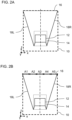
- the required aperture dimension at the coupling-in aperture of the LOE can be derived by tracing the light rays in the opposite direction, from the EMB via the coupling-out arrangement to the wave-guide entrance aperture. A trace of the most extreme angle rays from the eye box, expanding up towards the entrance aperture, is shown in FIG. 2A .
- the resulting required aperture dimension depends on the EMB size, the field of view, eye-to-entrance aperture distance and the refractive index.
- the present invention provides a projector, an optical system and a method for projecting an image in which the optical aperture 16 through which the image is coupled-in to the LOE is subdivided into a plurality of separate apertures, shown here as A1-A5, each having an independent projecting arrangement which projects the corresponding portion of the field of view. This is illustrated schematically in FIG. 2B .
- the optical system includes a light-guide optical element (LOE) 10 having two major parallel surfaces and configured for guiding illumination corresponding to a projected image collimated to infinity by internal reflection at the major parallel surfaces from a coupling-in region (effective aperture 16 ) to a coupling-out region (active area 14 ) where at least part of the illumination is coupled out towards an eye of the observer, located at an eye motion box (EMB) 12.
- a projector configuration is associated with the coupling-in region of the light-guide optical element.
- the projector configuration includes a plurality of adjacent optical arrangements or "subsystems", each having its own collimating optics deployed for projecting a subset of the illumination required from the overall effective aperture 16. The adjacent optical arrangements cooperate to provide an entirety of the projected image to the coupling-out region.
- each optical subsystem can project the entire FOV from each sub-aperture. However, as pointed out above with reference to FIG. 1B , this is wasteful, as much of the illumination from the lateral zones falls outside the EMB and is not needed. More preferably, when dividing the wave guide entrance aperture into several smaller zones, the field of view is also subdivided over the different zones so that each zone projects only the part of the field of view which is relevant for illuminating the EMB.
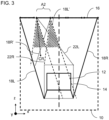
- FIG. 3 The determination of the field of view for each optical aperture is illustrated in FIG. 3 for an arbitrarily chosen aperture A2 as shown.
- a front view of LOE 10 generally similar to FIG. 2B and similarly labeled.
- the range of angles for which light from aperture A2 could reach the EMB 12 can be found by tracing a ray 22L from the left side of aperture A2 to the right extremity of the active area 14, corresponding to the furthest left part of the field which could reach the EMB, and a ray 22R from the right side of aperture A2 to the left extremity of the active area 14, corresponding to the furthest right part of the field which could reach the EMB from aperture A2.
- the relevant range of angles is of course also limited by the field of view (FOV) of the image, spanning angles from ray 18R' to ray 18L'.
- FOV field of view
- line 22L lies outside the FOV, so all rays up to the left edge of the FOV 18L' need to be displayed from aperture A2.
- line 22R defining the geometrical limit of rays that can reach the EMB, excludes part of the FOV, so that only pixels with angles from 22R inwards need to be displayed, and the remainder of the field between 22R and 18R' is unnecessary.
- CR chief ray
- the present invention provides a number of advantages compared to an equivalent display system employing a conventional projector to span the entire effective aperture 16. Specifically, by subdividing the aperture into multiple zones of smaller dimensions, the f-number of the optical arrangements is increased by a factor of (dtotal aperture / dzone) where dtotal aperture is the maximum dimension of the overall effective aperture, corresponding to a length L of the coupling-in region, and dzone is the maximum dimension of the separate optical arrangement exit aperture.
- the f-number of the individual optical arrangements is preferably at least 2, and more preferably at least 4, with certain particularly preferred implementations having an f-number of at least 5.
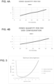
- the graphs of FIGS. 4A and 4B show an estimation of what number of subdivisions (or "partitions" or “zones") H is believed to be optimal in the case of a 16/9 ratio FoV with various angular sizes (with an EMB of 8x10 mm). These values are merely illustrative suggestions, and good results may also be achieved using either more or fewer subdivisions.
- advantages of subdividing the aperture in terms of increased f-number and reducing spherical aberration need to be balanced against the impact of the diffraction limit on spot size, as illustrated schematically in FIG. 5 .
- Acceptable and/or optimal ranges for aperture size can readily be selected by one ordinarily skilled in the art based on these considerations.
- the subdivision of the projector aperture into zones need not be performed with equal subdivisions. For example, considering that a small part of the FOV and a smaller proportion of image intensity is required per unit area in the peripheral apertures, it may be preferred to employ larger apertures towards the periphery of the overall aperture. On the other hand, certain particularly preferred implementations employ identical apertures and identical optical arrangements for all of the optical subsystems, thereby achieving simplification of the structure.
- Partitioning of the aperture can be implemented using a range of different optical architectures for the collimating optics module responsible for collimating the light beams exiting from a micro-display into the LOE entrance (coupling-in) aperture.
- the increased f-number and reduced optical requirements of the subdivided aperture approach facilitate implementation of a compact architecture based on refractive lenses.
- the use of refractive lenses allows the lens to be located on or right after the wave guide entrance aperture, thereby avoiding the further expansion of the field which occurs over the distance from the waveguide entrance to the collimating optics in a reflective optics PBS-based design.
- the proximity of the lens to the aperture allows the use of a lens which is roughly equal in size to the corresponding optical aperture of the assigned zone, resulting in a much more compact design than reflective optics implementation.
- each optical arrangement which includes 4 optical elements arranged as two doublets, such as for example a Petzval lens.
- An example of such an arrangement is shown in FIG. 6A as a single optical arrangement, with a first doublet 24 and a second doublet 26, the second doublet being aligned with a spatial light modulator component 28.
- FIGS. 6B and 6C illustrate schematically a full optical system including an array of, in this example, seven optical arrangements as in FIG.
- Each sub-aperture is preferably rectangular so that the juxtaposed sub-apertures form a substantially continuous effective aperture.
- Coupling-in is achieved here in this non-limiting example by use of a coupling prism 30 which presents a correctly inclined coupling in surface for introducing the image illumination into the LOE.
- the juxtaposed lenses or lens assemblies 24 are integrated into a first lens array which, for device assembly purposes, functions as a single element.
- the juxtaposed lenses or lens assemblies 26 are integrated into a second lens array which, for device assembly purposes, functions as a single element.
- the lens arrays may advantageously be produced by a molding process, rendering the structure particularly low cost and easy to assemble. Where each lens array provides a doublet lens of the corresponding lens assembly, the component lenses can be molded as two separate arrays which are subsequently assembled to form a doublet array. Alternatively, a two-component molding process may be used to directly produce the doublet lens array, using techniques known in the art of lens manufacture.
- a baffle arrangement formed with a plurality of opaque baffles 32 is interposed between first lens array 24 and second lens array 26 so as to reduce cross-talk between the collimating optics of the plurality of optical arrangements.
- the baffle arrangement may also serve as a spacer to define and maintain the required spacing between the lens arrays.
- the aforementioned refractive lens arrangement is only one non-limiting example, and that the present invention can be implemented with a wide range of other lens types and implementations, including but not limited to, spherical, aspherical or freeform refractive lenses formed from glass or plastic, diffractive lenses, Fresnel lenses, reflective lenses, and any combination of the above.
- the spatial light modulator components of a plurality of adjacent optical arrangements are provided by corresponding regions of a shared spatial light modulator device.
- the entire array of spatial light modulator components may be provided by a single elongated spatial light modulator extending the length of the array.
- a light emitting spatial light modulator such as an OLED display element, a backlit LCD panel, a micro LED display or a digital light processing (DLP) chip
- the display surface can be directly aligned with the optical arrangements for minimum weight and bulk.
- a reflective spatial light modulator such as an LCOS chip
- a beam splitter cube block is typically interposed between the collimating optics and the modulator to allow delivery of illumination to the modulator surface, as is known in the art.
- FIG. 7 represents schematically component modules of a first lens array 24, a second lens array 26 and an elongated spatial light modulator 28 ready for assembly together with a baffle arrangement (not shown) and an LOE (not shown) to form an optical system according to the present invention.
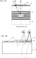
- FIG. 8A there is shown a variant implementation of the arrangement of FIG. 6C where one or more reflector 34 is provided to fold the optical path between the first and second lens arrays 24, 26, thereby facilitating a more compact implementation as shown.
- a pair of reflectors 34 fold the path twice through 90 degrees, allowing the optical components and spatial light modulator to be mounted on a common plane, for example, an extension of the coupling-in prism 30.
- FIG. 8B although the subdivision of the aperture 16 has thus far been illustrated only in the length dimension L, parallel to the plane of the LOE major surfaces, in certain cases, it may additionally be advantageous to subdivide the coupling-in aperture 16 in a perpendicular direction, corresponding to the two zones A1 and A2 illustrated in FIG. 8B .
- the FOV and chief rays for each subdivision across the aperture are typically identical, corresponding to the entire FOV in that dimension.
- FIG. 9 illustrates schematically a case where each of the optical arrangements projects the entirety of the FOV.
- each display generates an image corresponding to the full image to be displayed.
- This option may be preferred in a wide range of circumstances due to its structural simplicity and ease of alignment. It is however energetically inefficient, as explained above with reference to FIG. 1B , since much of the projected illumination is not directed towards the EMB and is therefore wasted. Additionally, it requires each collimating optics to handle a relatively wide angular FOV.
- FIGS. 10A and 10B illustrate an alternative approach, based on the analysis described above with reference to FIG. 3 according to which each optical arrangement projects only a partial image corresponding to a part of the overall image to be displayed for which the pixels are visible from the corresponding aperture at some location within the EMB.
- This reduces energy wastage, and reduces the FOV to be projected by at least some of the optical arrangements.
- each optical arrangement is preferably aligned so that the new chief ray CR corresponding to the center of the field projected by that arrangement lies on the optical axis of the collimating optics. This results in a construction as illustrated schematically in FIG. 10B , wherein each optical arrangement is oriented at a different angle. While this construction offers the aforementioned advantages over FIG. 9 of improved energy efficiency and reduced FOV requirements from the optical arrangements, the non-parallel deployment of the different projector subsystems may in some cases result in design complexity and engineering challenges.
- FIGS. 11A and 11B illustrate schematically a modified device conceptually similar to that of FIGS. 10A and 10B but modified by addition of respective beam deflecting optical elements 36 deployed to deflect the illumination path for each sub-projector so that all of the optical arrangements are arranged with parallel optical axes.
- the beam deflecting optical elements are a plurality of beam deflecting wedge prisms 36, each with a wedge angle chosen to correct the inclination of the corresponding chief beam of the aperture.
- the deflecting prism may be implemented as a doublet of two prisms to correct for chromatic dispersion.
- dispersion can be handled via digital correction of the projected image by displacing the color separations by a compensating offset.
- beam deflecting optical elements may also be used for implementing this aspect of the present invention, including but not limited to: direction turning film and diffractive optical elements.
- direction turning film and diffractive optical elements may also be used for implementing this aspect of the present invention, including but not limited to: direction turning film and diffractive optical elements.
- the central optical arrangement typically does not require a beam deflecting optical element.
- certain beam directions adjacent to the seams may be deflected sufficiently by the beam deflector 36 of one optical arrangement to enter the collimating optics 24 of an adjacent optical arrangement.
- the optical properties are analyzed by tracing beams in a reverse direction through the system, as if originating at the EMB and propagating into the projectors.
- stray beams could be eliminated by use of baffles or the like, that would still result in black lines in those regions of the display. This effect is illustrated schematically in FIG. 12 .
- a marginal region 28A of the spatial light modulator element outside the region 28 used for projecting the primary partial image of the sub-projector is actuated to generate a portion of the image, disjointed from the primary partial image, which supplies the correct image information to ray paths passing through the marginal region of the adjacent beam deflecting optical element.
- This strip of image, outside the direct FOV of the collimating optics, may be generated on both sides of the display.
- the optical system is incorporated into a head-mounted support structure, such as an eyeglasses frame configuration or a helmet visor, that supports the optical system in spaced relation to an eye of the observer such that the eye views the light-guide optical element from a position within a range of positions defining an eye-motion box.
- a head-mounted support structure such as an eyeglasses frame configuration or a helmet visor
- two such systems are provided to provide images to both eyes of the viewer.
- the coupling-out region is configured to deliver a field of view to the eye of the observer at all locations within the eye-motion box.
- the multiple optical arrangements cooperate to provide this full field of view, with each either projecting the entire FOV as per FIG. 9 or projecting partial images with overlapping but non-identical portions of the field of view as per FIGS. 10A-11B .
- the present invention is applicable to all display devices where the projector delivers illumination corresponding to an image, typically collimated to infinity, from an effective aperture of length L and width W via a light-guide optical element to an eye of a user, where the projector has at least three adjacent optical arrangements, each optical arrangement including a spatial light modulator component generating a projected image corresponding to at least part of the image, and collimating optics deployed for projecting the projected image as a collimated image via the light-guide optical element to an eye of the user. Exit apertures of all of the optical arrangements cooperate to span the length L of the effective aperture, and to deliver into the light-guide optical element an entirety of the illumination required for displaying the image to the observer.
- Embodiments of the present invention are applicable to a wide range of applications, particularly with asymmetric apertures such as a coupling-in region of an LOE, and for all types of LOE technology including, but not limited to, LOE's which include a coupling-out region with a plurality of partially-reflective surfaces deployed at an oblique angle to the major parallel surfaces, and LOE's which include a coupling-out region with at least one diffractive optical element deployed for coupling out image illumination towards the eye of the viewer.
- display devices employing the optical device of the present invention will include additional electronic components such as at least one processor or processing circuitry to drive the display device, all as is known in the art.
- additional electronic components such as at least one processor or processing circuitry to drive the display device, all as is known in the art.
- the necessary driver circuitry whether implemented as dedicated hardware, an ASIC, a general purpose processor operating under control of suitable software, or any hardware/software/firmware combination, will be readily understood by a person having ordinary skill in the art.
- Other hardware components such as power supplies, communication subsystems, illumination subsystems, sensors, input devices etc. are typically added, all in accordance with the device design and intended application, as will be clear to a person having ordinary skill in the art.
Abstract
A projector configuration for delivering illumination corresponding to an image from an effective aperture of length L and width W via a light-guide optical element to an eye of a user, the projector configuration comprising: at least three adjacent optical arrangements, each optical arrangement comprising: (a) a spatial light modulator component generating an output image corresponding to at least a part of the image; and (b) collimating optics deployed for projecting said output image as a collimated image having a central ray direction via the light-guide optical element to an eye of the user, said collimating optics having an exit aperture, wherein said exit apertures of said optical arrangements cooperate to span the length L of the effective aperture, and to deliver into the light-guide optical element an entirety of the illumination required for displaying the image to the observer, and wherein said collimating optics of said at least three adjacent optical arrangements have parallel central axes, the projector configuration further comprising a plurality of beam deflecting optical elements deployed to deflect said output image from a plurality of said adjacent optical arrangements to that said central ray directions converge.
Description
- The present invention relates to virtual reality and augmented reality displays and, in particular, it concerns a projector configuration for such displays in which an overall optical aperture for projection of an image into a light-guide optical element is subdivided into a number of separate smaller apertures.
- Many virtual reality and augmented reality displays employ a light-guide optical element (LOE) with two major parallel planar surfaces within which an image propagates by internal reflection. Illumination corresponding to a collimated image is introduced into the LOE at a coupling-in region, typically at one side, and propagates within the LOE by internal reflection until reaching a coupling-out region where it is coupled out of the LOE towards the viewer's eye. Coupling out of the illumination toward the eye may be by use of a set of obliquely angled partially reflective internal surfaces, such as described in
US patents 6,829,095 ,7,021,777 ,7,457,040 ,7,576,916 , or by use of one or more diffractive optical element, also as known in the art. - Although the LOE guides the illumination by internal reflection in one dimension, the dimension parallel to the plane of the LOE is not guided. As a result, in order to provide a full width of a desired field of view to the viewer, the in-plane dimension of the image projector introducing the image illumination into the coupling-in region needs to be relatively large. This results in a low f-number of the projector optics, often with f < 1, and imposes corresponding strict requirements on the optical design and quality of the optical components.
- The present invention provides a projector configuration and corresponding optical system for virtual reality and augmented reality head-up displays, particularly useful in near-eye displays, in which an optical aperture of an image projection system is partitioned (subdivided) into several zones, each with its own image generating and/or illumination subsystem.
- According to certain implementations of the present invention, this may reduce the overall form factor of an optical engine, and/or may increase the optical performance while maintaining a relatively small number of optical components (lenses).
- According to the teachings of the present invention there is provided, an optical system for displaying a projected image to an observer, the optical system comprising: (a) a light-guide optical element having two major parallel surfaces and configured for guiding illumination corresponding to a projected image collimated to infinity by internal reflection at the major parallel surfaces from a coupling-in region to a coupling-out region where at least part of the illumination is coupled out towards an eye of the observer; and (b) a projector configuration associated with the coupling-in region of the light-guide optical element, the projector configuration comprising a plurality of adjacent optical arrangements, each optical arrangement comprising collimating optics deployed for projecting a subset of the illumination, the adjacent optical arrangements cooperating to provide an entirety of the projected image to the coupling-out region.
- According to a further feature of an embodiment of the present invention, each of the optical arrangements further comprises a spatial light modulator component generating a partial image corresponding to a part of the image.
- According to a further feature of an embodiment of the present invention, the spatial light modulator components of the plurality of adjacent optical arrangements are provided by corresponding regions of a shared spatial light modulator device.
- According to a further feature of an embodiment of the present invention, the collimating optics of each of the plurality of optical arrangements comprises at least a first lens and at least a second lens, and wherein the first lenses for the plurality of optical arrangements are integrally formed into a first lens array and the second lenses for the plurality of optical arrangements are integrally formed into a second lens array.
- According to a further feature of an embodiment of the present invention, the projector configuration further comprises a baffle arrangement formed with a plurality of opaque baffles, the baffle arrangement being interposed between the first lens array and the second lens array so as to reduce cross-talk between the collimating optics of the plurality of optical arrangements.
- According to a further feature of an embodiment of the present invention, the plurality of optical arrangements include respective beam deflecting optical elements so that all of the optical arrangements are arranged with parallel optical axes.
- According to a further feature of an embodiment of the present invention, the beam deflecting optical elements comprise a plurality of beam deflecting prisms.
- According to a further feature of an embodiment of the present invention, the collimating optics of all of the plurality of optical arrangements are identical.
- According to a further feature of an embodiment of the present invention, each of the plurality of optical arrangements has an f-number of at least 2, and preferably at least 4.
- According to a further feature of an embodiment of the present invention, the optical system is incorporated into a head-mounted support structure configured to support the optical system in spaced relation to an eye of the observer such that the eye views the light-guide optical element from a range of positions defining an eye-motion box, and wherein the coupling-out region is configured to deliver a field of view to the eye of the observer at all locations within the eye-motion box, and wherein adjacent ones of the optical arrangement project overlapping but non-identical portions of the field of view.
- According to a further feature of an embodiment of the present invention, the subset of the illumination corresponds to an entirety of the image projected from a sub-region of the coupling-in region.
- According to an alternative feature of an embodiment of the present invention, the subset of the illumination for at least one of the optical arrangements corresponds to only part of the image.
- According to a further feature of an embodiment of the present invention, the coupling-out region comprises a plurality of partially-reflective surfaces deployed at an oblique angle to the major parallel surfaces.
- According to a further feature of an embodiment of the present invention, the coupling-out region comprises at least one diffractive optical element associated with one of the major parallel surfaces.
- There is also provided according to the teachings of an embodiment of the present invention, a projector configuration for delivering illumination corresponding to an image from an effective aperture of length L and width W via a light-guide optical element to an eye of a user, the projector configuration comprising at least three adjacent optical arrangements, each optical arrangement comprising: (a) a spatial light modulator component generating an output image corresponding to at least a part of the image; and (b) collimating optics deployed for projecting the output image as a collimated image via the light-guide optical element to an eye of the user, the collimating optics having an exit aperture, wherein the exit apertures of the optical arrangements cooperate to span the length L of the effective aperture, and to deliver into the light-guide optical element an entirety of the illumination required for displaying the image to the observer.
- According to a further feature of an embodiment of the present invention, the output image for at least one of the optical arrangements corresponds to only part of the image to be displayed.
- The invention is herein described, by way of example only, with reference to the accompanying drawings, wherein:
-
FIG. 1A is a schematic plan view of a field of view (FOV) projected from a light-guide optical element (LOE) towards an eye of an observer; -
FIG. 1B is schematic plan view similar toFIG. 1A illustrating a distribution of light from an active area of the LOE in order to provide the field of view over the entirety of an eye motion box (EMB); -
FIG. 2A is a schematic front view of an LOE illustrating the required length dimension of a coupling-in region of the LOE in order to provide the full FOV to the EMB; -
FIG. 2B is a view similar toFIG. 2A illustrating schematically the subdivision of the coupling-in region into sub-apertures according to an aspect of the present invention; -
FIG. 3 is a view similar toFIG. 2B illustrating the range of angles for which light from a given sub-aperture can reach the eye motion box; -
FIGS. 4A and 4B are graphs illustrating examples of a recommended number of sub-apertures as a function of image angular field of view for a top-down and a side-injected LOE configuration, respectively; -
FIG. 5 is a graph illustrating conflicting considerations for selecting a partition aperture size for certain implementations of the present invention; -
FIG. 6A is a schematic side view of a lens arrangement suitable for use in certain implementations of the present invention; -
FIG. 6B is a schematic front view of a display system employing a plurality of the lens arrangements ofFIG. 6A associated with an LOE; -
FIG. 6C is a schematic side view of the display system ofFIG. 6B ; -
FIG. 7 is a schematic isometric view of components of the display system ofFIG. 6B implemented as lens arrays for convenient assembly; -
FIG. 8A is a variant implementation of a display system similar toFIG. 6C illustrating the use of beam-folding reflectors to reduce the size of an optical arrangement; -
FIG. 8B is a further variant implementation of a display system similar toFIG. 6C in which the optical aperture is subdivided in two dimensions; -
FIG. 9 is a schematic representation of an optical architecture for implementing the present invention in which each sub-aperture is provided with the entire FOV of the projected image; -
FIG. 10A is a schematic front view of an LOE illustrating the orientation of the chief ray of two different sub-apertures, where each aperture projects only the parts of the image that fall within the EMB; -
FIG. 10B is a schematic representation of an optical architecture for implementing the present invention in which an optical arrangement associate with each sub-aperture projects a partial image aligned with the chief ray for that sub-aperture; -
FIGS. 11A and 11B are views similar toFIGS. 10A and 10B , respectively, illustrating the use of beam deflecting optical elements to redirect the chief rays of each sub-aperture; and -
FIG. 12 is a view similar toFIG. 11B illustrating use of peripheral regions of a spatial light modulator to provide compensatory image output. - The present invention provides a projector configuration and corresponding optical system for virtual reality and augmented reality head-up displays, particularly useful in near-eye displays, in which an optical aperture of an image projection system is partitioned (subdivided) into several zones, each with its own image generating and/or illumination subsystem.
- The principles and operation of projectors and optical systems according to the present invention may be better understood with reference to the drawings and the accompanying description.
- By way of introduction, referring to
FIGS. 1A, 1B and2A , a display based on a light-guide optical element (LOE) 10 is typically designed to provide the full field of view from aright-most ray 18R to aleft-most ray 18L to the eye of the viewer over the entirety of an "eye motion box" (EMB) 12 corresponding to the acceptable range of eye positions.FIG. 1A illustrates the field of view that is provided to the eye in a central position, whileFIG. 1B shows the required dimension of the display in the plane of the LOE (the "active area" 14 of the LOE 10) in order to provide all parts of the image to theentire EMB 12. The conventional approach typically provides all ray angles of the image projected from all parts of the LOE display area, although it will be noted that much of the image (rays 20) from the peripheral margins of the display area actually falls outside theEMB 12, and is therefore not in fact required. - The required aperture dimension at the coupling-in aperture of the LOE can be derived by tracing the light rays in the opposite direction, from the EMB via the coupling-out arrangement to the wave-guide entrance aperture. A trace of the most extreme angle rays from the eye box, expanding up towards the entrance aperture, is shown in
FIG. 2A . The resulting required aperture dimension depends on the EMB size, the field of view, eye-to-entrance aperture distance and the refractive index. - The result of this geometry is that the system has a large
effective optic aperture 16 in the plane of the LOE. This together with the desire to use short focal length in order to implement a compact projector arrangement results in a low f-number, with consequent demanding optical requirements and reduction in image quality compared to a higher f-number system. - To address this issue, the present invention provides a projector, an optical system and a method for projecting an image in which the
optical aperture 16 through which the image is coupled-in to the LOE is subdivided into a plurality of separate apertures, shown here as A1-A5, each having an independent projecting arrangement which projects the corresponding portion of the field of view. This is illustrated schematically inFIG. 2B . - Thus, regarding the optical system, in general terms, the optical system includes a light-guide optical element (LOE) 10 having two major parallel surfaces and configured for guiding illumination corresponding to a projected image collimated to infinity by internal reflection at the major parallel surfaces from a coupling-in region (effective aperture 16) to a coupling-out region (active area 14) where at least part of the illumination is coupled out towards an eye of the observer, located at an eye motion box (EMB) 12. A projector configuration is associated with the coupling-in region of the light-guide optical element. The projector configuration includes a plurality of adjacent optical arrangements or "subsystems", each having its own collimating optics deployed for projecting a subset of the illumination required from the overall
effective aperture 16. The adjacent optical arrangements cooperate to provide an entirety of the projected image to the coupling-out region. - In a basic implementation, each optical subsystem can project the entire FOV from each sub-aperture. However, as pointed out above with reference to
FIG. 1B , this is wasteful, as much of the illumination from the lateral zones falls outside the EMB and is not needed. More preferably, when dividing the wave guide entrance aperture into several smaller zones, the field of view is also subdivided over the different zones so that each zone projects only the part of the field of view which is relevant for illuminating the EMB. - The determination of the field of view for each optical aperture is illustrated in
FIG. 3 for an arbitrarily chosen aperture A2 as shown. Specifically, there is shown a front view ofLOE 10 generally similar toFIG. 2B and similarly labeled. The range of angles for which light from aperture A2 could reach theEMB 12 can be found by tracing aray 22L from the left side of aperture A2 to the right extremity of theactive area 14, corresponding to the furthest left part of the field which could reach the EMB, and aray 22R from the right side of aperture A2 to the left extremity of theactive area 14, corresponding to the furthest right part of the field which could reach the EMB from aperture A2. The relevant range of angles is of course also limited by the field of view (FOV) of the image, spanning angles fromray 18R' toray 18L'. In the case of the left side of the field,line 22L lies outside the FOV, so all rays up to the left edge of theFOV 18L' need to be displayed from aperture A2. On the right side of the field,line 22R, defining the geometrical limit of rays that can reach the EMB, excludes part of the FOV, so that only pixels with angles from 22R inwards need to be displayed, and the remainder of the field between 22R and 18R' is unnecessary. In order to optimize performance of the collimating optics, it is preferable to define the projector arrangement according to an adjusted chief ray (CR) corresponding to the middle of the projected field for that projector, which will be different for each projector. - It will be immediately apparent that the present invention provides a number of advantages compared to an equivalent display system employing a conventional projector to span the entire
effective aperture 16. Specifically, by subdividing the aperture into multiple zones of smaller dimensions, the f-number of the optical arrangements is increased by a factor of (dtotal aperture / dzone) where dtotal aperture is the maximum dimension of the overall effective aperture, corresponding to a length L of the coupling-in region, and dzone is the maximum dimension of the separate optical arrangement exit aperture. The f-number of the individual optical arrangements is preferably at least 2, and more preferably at least 4, with certain particularly preferred implementations having an f-number of at least 5. This compares to projectors for conventional LOE-based displays which typically have an f-number of less than 1, and often closer to ½. This increase in f-number leads to a corresponding relaxation of requirements on the properties of the optical arrangements, facilitating high quality image projection using relatively simple and low-cost optical components. - The graphs of
FIGS. 4A and 4B show an estimation of what number of subdivisions (or "partitions" or "zones") H is believed to be optimal in the case of a 16/9 ratio FoV with various angular sizes (with an EMB of 8x10 mm). These values are merely illustrative suggestions, and good results may also be achieved using either more or fewer subdivisions. When designing a system with small dimensions, such as for a near-eye display, advantages of subdividing the aperture in terms of increased f-number and reducing spherical aberration need to be balanced against the impact of the diffraction limit on spot size, as illustrated schematically inFIG. 5 . Acceptable and/or optimal ranges for aperture size can readily be selected by one ordinarily skilled in the art based on these considerations. - It should be noted that the subdivision of the projector aperture into zones need not be performed with equal subdivisions. For example, considering that a small part of the FOV and a smaller proportion of image intensity is required per unit area in the peripheral apertures, it may be preferred to employ larger apertures towards the periphery of the overall aperture. On the other hand, certain particularly preferred implementations employ identical apertures and identical optical arrangements for all of the optical subsystems, thereby achieving simplification of the structure.
- Partitioning of the aperture can be implemented using a range of different optical architectures for the collimating optics module responsible for collimating the light beams exiting from a micro-display into the LOE entrance (coupling-in) aperture. In addition to the Polarizing Beam Splitters collimating optics architecture described for example in
US patent 8,643,948 , the increased f-number and reduced optical requirements of the subdivided aperture approach facilitate implementation of a compact architecture based on refractive lenses. The use of refractive lenses allows the lens to be located on or right after the wave guide entrance aperture, thereby avoiding the further expansion of the field which occurs over the distance from the waveguide entrance to the collimating optics in a reflective optics PBS-based design. The proximity of the lens to the aperture allows the use of a lens which is roughly equal in size to the corresponding optical aperture of the assigned zone, resulting in a much more compact design than reflective optics implementation. - The less-stringent optical performance requirements resulting from the subdivision of the overall aperture and the consequent relatively high f-number for each optical arrangement allows the use of relatively simple collimating optics while preserving high quality image output. For example, certain implementations of the invention employ collimating optics for each optical arrangement which includes 4 optical elements arranged as two doublets, such as for example a Petzval lens. An example of such an arrangement is shown in
FIG. 6A as a single optical arrangement, with afirst doublet 24 and asecond doublet 26, the second doublet being aligned with a spatiallight modulator component 28.FIGS. 6B and 6C illustrate schematically a full optical system including an array of, in this example, seven optical arrangements as inFIG. 6A together spanning the coupling-in effective aperture of anLOE 10. Each sub-aperture is preferably rectangular so that the juxtaposed sub-apertures form a substantially continuous effective aperture. Coupling-in is achieved here in this non-limiting example by use of acoupling prism 30 which presents a correctly inclined coupling in surface for introducing the image illumination into the LOE. - According to one particularly preferred implementation, the juxtaposed lenses or
lens assemblies 24 are integrated into a first lens array which, for device assembly purposes, functions as a single element. Similarly, the juxtaposed lenses orlens assemblies 26 are integrated into a second lens array which, for device assembly purposes, functions as a single element. The lens arrays may advantageously be produced by a molding process, rendering the structure particularly low cost and easy to assemble. Where each lens array provides a doublet lens of the corresponding lens assembly, the component lenses can be molded as two separate arrays which are subsequently assembled to form a doublet array. Alternatively, a two-component molding process may be used to directly produce the doublet lens array, using techniques known in the art of lens manufacture. Preferably, a baffle arrangement formed with a plurality ofopaque baffles 32 is interposed betweenfirst lens array 24 andsecond lens array 26 so as to reduce cross-talk between the collimating optics of the plurality of optical arrangements. The baffle arrangement may also serve as a spacer to define and maintain the required spacing between the lens arrays. - It should be appreciated that the aforementioned refractive lens arrangement is only one non-limiting example, and that the present invention can be implemented with a wide range of other lens types and implementations, including but not limited to, spherical, aspherical or freeform refractive lenses formed from glass or plastic, diffractive lenses, Fresnel lenses, reflective lenses, and any combination of the above.
- According to a further preferred feature, which may be implemented as part of the above lens array construction or with separate optical arrangements, the spatial light modulator components of a plurality of adjacent optical arrangements are provided by corresponding regions of a shared spatial light modulator device. In some cases, the entire array of spatial light modulator components may be provided by a single elongated spatial light modulator extending the length of the array. In the case of a light emitting spatial light modulator, such as an OLED display element, a backlit LCD panel, a micro LED display or a digital light processing (DLP) chip, the display surface can be directly aligned with the optical arrangements for minimum weight and bulk. If it is desired to use a reflective spatial light modulator, such as an LCOS chip, a beam splitter cube block is typically interposed between the collimating optics and the modulator to allow delivery of illumination to the modulator surface, as is known in the art.
-
FIG. 7 represents schematically component modules of afirst lens array 24, asecond lens array 26 and an elongated spatiallight modulator 28 ready for assembly together with a baffle arrangement (not shown) and an LOE (not shown) to form an optical system according to the present invention. - Turning to
FIG. 8A , there is shown a variant implementation of the arrangement ofFIG. 6C where one ormore reflector 34 is provided to fold the optical path between the first andsecond lens arrays reflectors 34 fold the path twice through 90 degrees, allowing the optical components and spatial light modulator to be mounted on a common plane, for example, an extension of the coupling-inprism 30. - Turning to
FIG. 8B , although the subdivision of theaperture 16 has thus far been illustrated only in the length dimension L, parallel to the plane of the LOE major surfaces, in certain cases, it may additionally be advantageous to subdivide the coupling-inaperture 16 in a perpendicular direction, corresponding to the two zones A1 and A2 illustrated inFIG. 8B . In this case, the FOV and chief rays for each subdivision across the aperture are typically identical, corresponding to the entire FOV in that dimension. - Turning now to
FIGS. 9-12 , a number of options will be discussed regarding the FOV projected by each of the optical arrangements from each of the aperture zones, and the geometry of the projection arrangement.FIG. 9 illustrates schematically a case where each of the optical arrangements projects the entirety of the FOV. (In this drawing and each of the following drawings, only selected rays indicative of the optical performance for two sample aperture zones are shown for simplicity of presentation.) In this case, all of the optical arrangements are deployed with their optical axes parallel, and each display generates an image corresponding to the full image to be displayed. This option may be preferred in a wide range of circumstances due to its structural simplicity and ease of alignment. It is however energetically inefficient, as explained above with reference toFIG. 1B , since much of the projected illumination is not directed towards the EMB and is therefore wasted. Additionally, it requires each collimating optics to handle a relatively wide angular FOV. -
FIGS. 10A and 10B illustrate an alternative approach, based on the analysis described above with reference toFIG. 3 according to which each optical arrangement projects only a partial image corresponding to a part of the overall image to be displayed for which the pixels are visible from the corresponding aperture at some location within the EMB. This reduces energy wastage, and reduces the FOV to be projected by at least some of the optical arrangements. To optimize performance of the optical arrangement, each optical arrangement is preferably aligned so that the new chief ray CR corresponding to the center of the field projected by that arrangement lies on the optical axis of the collimating optics. This results in a construction as illustrated schematically inFIG. 10B , wherein each optical arrangement is oriented at a different angle. While this construction offers the aforementioned advantages overFIG. 9 of improved energy efficiency and reduced FOV requirements from the optical arrangements, the non-parallel deployment of the different projector subsystems may in some cases result in design complexity and engineering challenges. -
FIGS. 11A and 11B illustrate schematically a modified device conceptually similar to that ofFIGS. 10A and 10B but modified by addition of respective beam deflectingoptical elements 36 deployed to deflect the illumination path for each sub-projector so that all of the optical arrangements are arranged with parallel optical axes. In the particularly preferred implementation illustrated here, the beam deflecting optical elements are a plurality of beam deflectingwedge prisms 36, each with a wedge angle chosen to correct the inclination of the corresponding chief beam of the aperture. Optionally, the deflecting prism may be implemented as a doublet of two prisms to correct for chromatic dispersion. Alternatively, dispersion can be handled via digital correction of the projected image by displacing the color separations by a compensating offset. It should be noted that other types of beam deflecting optical elements may also be used for implementing this aspect of the present invention, including but not limited to: direction turning film and diffractive optical elements. Where one of the optical arrangements lies on the optical axis of symmetry of the LOE (typically when there are an odd number of apertures), the central optical arrangement typically does not require a beam deflecting optical element. - Throughout the above-described implementations of the present invention, care should be taken to minimize gaps or obscurations at the junctions between adjacent lenses defining the adjacent partial apertures so as to avoid or minimize dark lines and other edge-related distortions. Various design choices, such as the use of high refractive index materials or the use of Fresnel lenses allow implementations with relatively flat or large-radius curvature of the outer surfaces, facilitating extending the optical performance up to the seam between the apertures, and minimizing any "black line" effect.
- In certain situations, particularly where a beam deflecting
optical element 36 is used, and theexit apertures 24 of the optical arrangements are somewhat set back from the beam deflecting optical elements, certain beam directions adjacent to the seams may be deflected sufficiently by thebeam deflector 36 of one optical arrangement to enter thecollimating optics 24 of an adjacent optical arrangement. (Here, as elsewhere in the description, the optical properties are analyzed by tracing beams in a reverse direction through the system, as if originating at the EMB and propagating into the projectors.) Although such stray beams could be eliminated by use of baffles or the like, that would still result in black lines in those regions of the display. This effect is illustrated schematically inFIG. 12 . - To address this issue, it is noted that the location of the stray rays from the adjacent beam deflecting optical element arriving at the plane of the spatial
light modulator 28 lie outside the field of view of the projected image for that optical arrangement. As a result, according to a further aspect of the present invention, amarginal region 28A of the spatial light modulator element outside theregion 28 used for projecting the primary partial image of the sub-projector is actuated to generate a portion of the image, disjointed from the primary partial image, which supplies the correct image information to ray paths passing through the marginal region of the adjacent beam deflecting optical element. This strip of image, outside the direct FOV of the collimating optics, may be generated on both sides of the display. - The various embodiments of the present invention may be implemented in a wide range of contexts and applications. According to one particularly preferred but non-limiting set of implementations, the optical system is incorporated into a head-mounted support structure, such as an eyeglasses frame configuration or a helmet visor, that supports the optical system in spaced relation to an eye of the observer such that the eye views the light-guide optical element from a position within a range of positions defining an eye-motion box. In some cases, two such systems are provided to provide images to both eyes of the viewer. The coupling-out region is configured to deliver a field of view to the eye of the observer at all locations within the eye-motion box. The multiple optical arrangements cooperate to provide this full field of view, with each either projecting the entire FOV as per
FIG. 9 or projecting partial images with overlapping but non-identical portions of the field of view as perFIGS. 10A-11B . - The present invention is applicable to all display devices where the projector delivers illumination corresponding to an image, typically collimated to infinity, from an effective aperture of length L and width W via a light-guide optical element to an eye of a user, where the projector has at least three adjacent optical arrangements, each optical arrangement including a spatial light modulator component generating a projected image corresponding to at least part of the image, and collimating optics deployed for projecting the projected image as a collimated image via the light-guide optical element to an eye of the user. Exit apertures of all of the optical arrangements cooperate to span the length L of the effective aperture, and to deliver into the light-guide optical element an entirety of the illumination required for displaying the image to the observer.
- Embodiments of the present invention are applicable to a wide range of applications, particularly with asymmetric apertures such as a coupling-in region of an LOE, and for all types of LOE technology including, but not limited to, LOE's which include a coupling-out region with a plurality of partially-reflective surfaces deployed at an oblique angle to the major parallel surfaces, and LOE's which include a coupling-out region with at least one diffractive optical element deployed for coupling out image illumination towards the eye of the viewer.
- It will be appreciated that display devices employing the optical device of the present invention will include additional electronic components such as at least one processor or processing circuitry to drive the display device, all as is known in the art. Where different spatial light modulators, or different regions of a single spatial light modulator, are driven in parallel to generate similar images, or are driven to generate different partial images, each aligned with the corresponding collimating optics, the necessary driver circuitry, whether implemented as dedicated hardware, an ASIC, a general purpose processor operating under control of suitable software, or any hardware/software/firmware combination, will be readily understood by a person having ordinary skill in the art. Other hardware components, such as power supplies, communication subsystems, illumination subsystems, sensors, input devices etc. are typically added, all in accordance with the device design and intended application, as will be clear to a person having ordinary skill in the art.
- It will be appreciated that the above descriptions are intended only to serve as examples, and that many other embodiments are possible within the scope of the present invention as defined in the appended claims.
Claims (12)
- A projector configuration for delivering illumination corresponding to an image from an effective aperture of length L and width W via a light-guide optical element to an eye of a user, the projector configuration comprising:
at least three adjacent optical arrangements, each optical arrangement comprising:(a) a spatial light modulator component generating an output image corresponding to at least a part of the image; and(b) collimating optics deployed for projecting said output image as a collimated image having a central ray direction via the light-guide optical element to an eye of the user, said collimating optics having an exit aperture, wherein said exit apertures of said optical arrangements cooperate to span the length L of the effective aperture, and to deliver into the light-guide optical element an entirety of the illumination required for displaying the image to the observer, and wherein said collimating optics of said at least three adjacent optical arrangements have parallel central axes, the projector configuration further comprising a plurality of beam deflecting optical elements deployed to deflect said output image from a plurality of said adjacent optical arrangements to that said central ray directions converge. - The projector configuration of claim 1, wherein said output image for at least one of said optical arrangements corresponds to only part of the image to be displayed.
- The projector configuration of claim 1, wherein each of said beam deflecting optical elements is a prism.
- The projector configuration of claim 1, wherein said spatial light modulator components of said at least three adjacent optical arrangements are provided by regions of a single spatial light modulator.
- The projector configuration of claim 1, wherein said collimating optics of each of said at least three adjacent optical arrangements comprises at least a first lens and at least a second lens, and wherein said first lenses for said at least three adjacent optical arrangements are integrally formed into a first lens array and said second lenses for said at least three adjacent optical arrangements are integrally formed into a second lens array.
- The projector configuration of claim 1, wherein said collimating optics of all of said at least three adjacent optical arrangements are identical.
- The projector configuration of claim 1, wherein each of said at least three adjacent optical arrangements has an f-number of at least 2.
- The projector configuration of claim 1, wherein each of said at least three adjacent optical arrangements has an f-number of at least 4.
- The projector configuration according to claim 1, wherein said collimating optics of each of said at least three adjacent optical arrangements comprises at least a first lens and at least a second lens, and wherein said first lenses for said at least three adjacent optical arrangements are integrally formed into a first lens array and said second lenses for said at least three adjacent optical arrangements are integrally formed into a second lens array, and further comprising a baffle arrangement formed with a plurality of opaque baffles, said baffle arrangement being interposed between said first lens array and said second lens array so as to reduce cross-talk between said collimating optics of said at least three adjacent optical arrangements.
- The projector configuration according to claim 1, further comprising:
a light-guide optical element having two major parallel surfaces, wherein said at least three adjacent optical arrangements are optically couple to said light-guide optical element so as to introduce said output images into said light-guide optical element so as to propagate within said light-guide optical element by internal reflection at said major parallel surfaces to a coupling-out region where at least part of said illumination is coupled out towards the eye of the user, and wherein said length L of said effective optical aperture extends parallel to said major parallel surfaces. - The projector configuration of claim 10, wherein said coupling-out region comprises a plurality of partially-reflective surfaces deployed at an oblique angle to said major parallel surfaces.
- The projector configuration of claim 10, wherein said coupling-out region comprises at least one diffractive optical element associated with one of said major parallel surfaces.
Applications Claiming Priority (3)
| Application Number | Priority Date | Filing Date | Title |
|---|---|---|---|
| US201862670886P | 2018-05-14 | 2018-05-14 | |
| EP19802792.2A EP3625617B1 (en) | 2018-05-14 | 2019-05-14 | Projector configuration with subdivided optical aperture for near-eye displays, and corresponding optical systems |
| PCT/IB2019/053972 WO2019220330A1 (en) | 2018-05-14 | 2019-05-14 | Projector configuration with subdivided optical aperture for near-eye displays, and corresponding optical systems |
Related Parent Applications (2)
| Application Number | Title | Priority Date | Filing Date |
|---|---|---|---|
| EP19802792.2A Division EP3625617B1 (en) | 2018-05-14 | 2019-05-14 | Projector configuration with subdivided optical aperture for near-eye displays, and corresponding optical systems |
| PCT/IB2019/053972 Previously-Filed-Application WO2019220330A1 (en) | 2018-05-14 | 2019-05-14 | Projector configuration with subdivided optical aperture for near-eye displays, and corresponding optical systems |
Publications (1)
| Publication Number | Publication Date |
|---|---|
| EP4339656A2 true EP4339656A2 (en) | 2024-03-20 |
Family
ID=68464597
Family Applications (2)
| Application Number | Title | Priority Date | Filing Date |
|---|---|---|---|
| EP19802792.2A Active EP3625617B1 (en) | 2018-05-14 | 2019-05-14 | Projector configuration with subdivided optical aperture for near-eye displays, and corresponding optical systems |
| EP23193946.3A Pending EP4339656A2 (en) | 2018-05-14 | 2019-05-14 | Projector configuration with subdivided optical aperture for near-eye displays, and corresponding optical systems |
Family Applications Before (1)
| Application Number | Title | Priority Date | Filing Date |
|---|---|---|---|
| EP19802792.2A Active EP3625617B1 (en) | 2018-05-14 | 2019-05-14 | Projector configuration with subdivided optical aperture for near-eye displays, and corresponding optical systems |
Country Status (8)
| Country | Link |
|---|---|
| US (2) | US10830938B2 (en) |
| EP (2) | EP3625617B1 (en) |
| JP (2) | JP7416407B2 (en) |
| KR (1) | KR20210008294A (en) |
| CN (1) | CN112119346B (en) |
| IL (1) | IL278588B (en) |
| TW (1) | TW201947264A (en) |
| WO (1) | WO2019220330A1 (en) |
Families Citing this family (41)
| Publication number | Priority date | Publication date | Assignee | Title |
|---|---|---|---|---|
| US10261321B2 (en) | 2005-11-08 | 2019-04-16 | Lumus Ltd. | Polarizing optical system |
| IL232197B (en) | 2014-04-23 | 2018-04-30 | Lumus Ltd | Compact head-mounted display system |
| IL235642B (en) | 2014-11-11 | 2021-08-31 | Lumus Ltd | Compact head-mounted display system protected by a hyperfine structure |
| IL237337B (en) | 2015-02-19 | 2020-03-31 | Amitai Yaakov | Compact head-mounted display system having uniform image |
| KR20230066124A (en) | 2016-10-09 | 2023-05-12 | 루머스 리미티드 | Aperture multiplier using a rectangular waveguide |
| RU2763850C2 (en) | 2016-11-08 | 2022-01-11 | Люмус Лтд | Lightguide device with edge providing optical cutoff and corresponding manufacturing methods |
| CN110431467A (en) | 2017-01-28 | 2019-11-08 | 鲁姆斯有限公司 | Augmented reality imaging system |
| CN117572644A (en) | 2017-03-22 | 2024-02-20 | 鲁姆斯有限公司 | Method for producing a light-guiding optical element and optical system |
| CN110869839B (en) | 2017-07-19 | 2022-07-08 | 鲁姆斯有限公司 | Liquid crystal on silicon illuminator with light guide optical element |
| KR102561362B1 (en) | 2017-09-29 | 2023-07-28 | 루머스 리미티드 | augmented reality display |
| CN111133362B (en) | 2017-10-22 | 2021-12-28 | 鲁姆斯有限公司 | Head-mounted augmented reality device employing optical bench |
| KR20200096274A (en) | 2017-12-03 | 2020-08-11 | 루머스 리미티드 | Optical device alignment method |
| MX2020002402A (en) | 2018-01-02 | 2020-07-22 | Lumus Ltd | Augmented reality displays with active alignment and corresponding methods. |
| US10551544B2 (en) | 2018-01-21 | 2020-02-04 | Lumus Ltd. | Light-guide optical element with multiple-axis internal aperture expansion |
| US11221294B2 (en) | 2018-04-08 | 2022-01-11 | Lumus Ltd. | Optical sample characterization |
| US10830938B2 (en) | 2018-05-14 | 2020-11-10 | Lumus Ltd. | Projector configuration with subdivided optical aperture for near-eye displays, and corresponding optical systems |
| EP3794397A4 (en) | 2018-05-17 | 2021-07-07 | Lumus Ltd. | Near-eye display having overlapping projector assemblies |
| IL259518B2 (en) | 2018-05-22 | 2023-04-01 | Lumus Ltd | Optical system and method for improvement of light field uniformity |
| TWI813691B (en) | 2018-05-23 | 2023-09-01 | 以色列商魯姆斯有限公司 | Optical system including light-guide optical element with partially-reflective internal surfaces |
| WO2019244093A1 (en) | 2018-06-21 | 2019-12-26 | Lumus Ltd. | Measurement technique for refractive index inhomogeneity between plates of a lightguide optical element (loe) |
| US11415812B2 (en) | 2018-06-26 | 2022-08-16 | Lumus Ltd. | Compact collimating optical device and system |
| US11409103B2 (en) | 2018-07-16 | 2022-08-09 | Lumus Ltd. | Light-guide optical element employing polarized internal reflectors |
| JP7407458B2 (en) | 2018-09-09 | 2024-01-04 | ルムス エルティーディー. | Optical system including light-guiding optical element with two-dimensional extension |
| EP3867696B1 (en) | 2018-11-08 | 2022-08-03 | Lumus Ltd. | Optical devices and systems with dichroic beamsplitter color combiner |
| TW202026685A (en) | 2018-11-08 | 2020-07-16 | 以色列商魯姆斯有限公司 | Light-guide display with reflector |
| JP3226277U (en) | 2018-11-11 | 2020-05-14 | ルムス エルティーディー. | Near eye display with intermediate window |
| WO2020152688A1 (en) | 2019-01-24 | 2020-07-30 | Lumus Ltd. | Optical systems including loe with three stage expansion |
| US11849262B2 (en) | 2019-03-12 | 2023-12-19 | Lumus Ltd. | Image projector |
| BR112021022229A2 (en) | 2019-06-27 | 2022-02-22 | Lumus Ltd | Device |
| KR102622406B1 (en) | 2019-11-25 | 2024-01-05 | 루머스 리미티드 | How to polish the surface of a waveguide |
| IL270991B (en) | 2019-11-27 | 2020-07-30 | Lumus Ltd | Lightguide optical element for polarization scrambling |
| CA3162579C (en) | 2019-12-05 | 2024-01-30 | Lumus Ltd | Light-guide optical element employing complementary coated partial reflectors, and light-guide optical element having reduced light scattering |
| EP4042232A4 (en) | 2019-12-08 | 2022-12-28 | Lumus Ltd. | Optical systems with compact image projector |
| WO2021240513A1 (en) * | 2020-05-24 | 2021-12-02 | Lumus Ltd. | Compound light-guide optical elements |
| DE202021104723U1 (en) | 2020-09-11 | 2021-10-18 | Lumus Ltd. | Image projector coupled to an optical light guide element |
| US11947134B2 (en) | 2021-01-22 | 2024-04-02 | National Taiwan University | Device of generating 3D light-field image |
| EP4237903A4 (en) | 2021-03-01 | 2024-04-24 | Lumus Ltd | Optical system with compact coupling from a projector into a waveguide |
| US11789264B2 (en) | 2021-07-04 | 2023-10-17 | Lumus Ltd. | Display with stacked light-guide elements providing different parts of field of view |
| CN115616774A (en) * | 2021-07-15 | 2023-01-17 | 上海鲲游科技有限公司 | Aperture-divided micro-projection device and method thereof |
| US11741861B1 (en) * | 2022-02-08 | 2023-08-29 | Lumus Ltd. | Optical system including selectively activatable facets |
| CN115113402B (en) * | 2022-06-21 | 2023-07-14 | 湖北大学 | Large-view-field automobile head-up display device and implementation method thereof |
Citations (4)
| Publication number | Priority date | Publication date | Assignee | Title |
|---|---|---|---|---|
| US6829095B2 (en) | 2000-06-05 | 2004-12-07 | Lumus, Ltd. | Substrate-guided optical beam expander |
| US7021777B2 (en) | 2003-09-10 | 2006-04-04 | Lumus Ltd. | Optical devices particularly for remote viewing applications |
| US7457040B2 (en) | 2002-03-21 | 2008-11-25 | Lumus Ltd. | Light guide optical device |
| US8643948B2 (en) | 2007-04-22 | 2014-02-04 | Lumus Ltd. | Collimating optical device and system |
Family Cites Families (106)
| Publication number | Priority date | Publication date | Assignee | Title |
|---|---|---|---|---|
| US2329001A (en) | 1941-11-25 | 1943-09-07 | Randolph B Delmore | Pilot operated valve |
| FR1485692A (en) | 1966-05-11 | 1967-06-23 | Advanced valve | |
| US3544190A (en) * | 1968-11-29 | 1970-12-01 | Xerox Corp | Lens strip optical scanning system |
| FR2617562B1 (en) | 1987-07-01 | 1989-11-10 | Verdelet Alain | VALVE VALVE ASSEMBLY |
| US5770847A (en) * | 1994-12-23 | 1998-06-23 | Spectra-Physics Scanning Systems, Inc. | Bar code reader with multi-focus lens |
| US5999836A (en) * | 1995-06-06 | 1999-12-07 | Nelson; Robert S. | Enhanced high resolution breast imaging device and method utilizing non-ionizing radiation of narrow spectral bandwidth |
| GB0112871D0 (en) * | 2001-05-26 | 2001-07-18 | Thales Optics Ltd | Improved optical device |
| US6752169B2 (en) | 2002-10-31 | 2004-06-22 | Lindsay Manufacturing Co. | Pressure regulator and shut-off valve |
| US7298940B2 (en) * | 2003-06-10 | 2007-11-20 | Abu-Ageel Nayef M | Illumination system and display system employing same |
| US7475992B2 (en) * | 2003-06-10 | 2009-01-13 | Abu-Ageel Nayef M | Light recycler and color display system including same |
| US7400447B2 (en) * | 2003-09-03 | 2008-07-15 | Canon Kabushiki Kaisha | Stereoscopic image display device |
| IL157838A (en) | 2003-09-10 | 2013-05-30 | Yaakov Amitai | High brightness optical device |
| IL157837A (en) | 2003-09-10 | 2012-12-31 | Yaakov Amitai | Substrate-guided optical device particularly for three-dimensional displays |
| IL162573A (en) * | 2004-06-17 | 2013-05-30 | Lumus Ltd | Substrate-guided optical device with very wide aperture |
| US20070202285A1 (en) | 2004-12-15 | 2007-08-30 | Fina Technology, Inc. | Articles having improved clarity, prepared from propylene-ethylene copolymers |
| US7413328B2 (en) * | 2004-12-30 | 2008-08-19 | Honeywell International Inc. | Remotely coupled hybrid HUD backlight |
| EP1849033B1 (en) | 2005-02-10 | 2019-06-19 | Lumus Ltd | Substrate-guided optical device utilizing thin transparent layer |
| US10073264B2 (en) | 2007-08-03 | 2018-09-11 | Lumus Ltd. | Substrate-guide optical device |
| IL166799A (en) | 2005-02-10 | 2014-09-30 | Lumus Ltd | Substrate-guided optical device utilizing beam splitters |
| WO2006085310A1 (en) | 2005-02-10 | 2006-08-17 | Lumus Ltd. | Substrate-guided optical device particularly for vision enhanced optical systems |
| EP1848966A1 (en) | 2005-02-17 | 2007-10-31 | Lumus Ltd | Personal navigation system |
| JP2006350138A (en) * | 2005-06-17 | 2006-12-28 | Toshiba Corp | Image display apparatus |
| US7434940B2 (en) | 2005-09-06 | 2008-10-14 | Hewlett-Packard Development Company, L.P. | Light coupling system and method |
| US20080043334A1 (en) * | 2006-08-18 | 2008-02-21 | Mirage Innovations Ltd. | Diffractive optical relay and method for manufacturing the same |
| US10261321B2 (en) | 2005-11-08 | 2019-04-16 | Lumus Ltd. | Polarizing optical system |
| IL171820A (en) | 2005-11-08 | 2014-04-30 | Lumus Ltd | Polarizing optical device for light coupling |
| US7701388B2 (en) | 2005-11-15 | 2010-04-20 | O2Micro International Ltd. | Novas hybrid positioning technology using terrestrial digital broadcasting signal (DBS) and global positioning system (GPS) satellite signal |
| IL173715A0 (en) | 2006-02-14 | 2007-03-08 | Lumus Ltd | Substrate-guided imaging lens |
| IL174170A (en) | 2006-03-08 | 2015-02-26 | Abraham Aharoni | Device and method for binocular alignment |
| US7830608B2 (en) * | 2006-05-20 | 2010-11-09 | Oclaro Photonics, Inc. | Multiple emitter coupling devices and methods with beam transform system |
| IL177618A (en) | 2006-08-22 | 2015-02-26 | Lumus Ltd | Substrate- guided optical device |
| IL183637A (en) | 2007-06-04 | 2013-06-27 | Zvi Lapidot | Distributed head-mounted display |
| JP5031452B2 (en) | 2007-06-20 | 2012-09-19 | キヤノン株式会社 | Image observation apparatus and image observation system |
| US20090126792A1 (en) * | 2007-11-16 | 2009-05-21 | Qualcomm Incorporated | Thin film solar concentrator/collector |
| US7949252B1 (en) * | 2008-12-11 | 2011-05-24 | Adobe Systems Incorporated | Plenoptic camera with large depth of field |
| ES2721600T5 (en) * | 2008-12-12 | 2022-04-11 | Bae Systems Plc | Improvements in or related to waveguides |
| JP2010266787A (en) | 2009-05-18 | 2010-11-25 | Canon Inc | Image display apparatus |
| US8730183B2 (en) | 2009-09-03 | 2014-05-20 | Obscura Digital | Large scale multi-user, multi-touch system |
| US9341846B2 (en) * | 2012-04-25 | 2016-05-17 | Rockwell Collins Inc. | Holographic wide angle display |
| US9110495B2 (en) | 2010-02-03 | 2015-08-18 | Microsoft Technology Licensing, Llc | Combined surface user interface |
| CN102782562B (en) | 2010-04-30 | 2015-07-22 | 北京理工大学 | Wide angle and high resolution tiled head-mounted display device |
| KR101812299B1 (en) * | 2010-07-06 | 2017-12-27 | 시리얼 테크놀로지즈 에스.에이. | Beam divergence and various collimators for holographic or stereoscopic displays |
| US8649099B2 (en) * | 2010-09-13 | 2014-02-11 | Vuzix Corporation | Prismatic multiple waveguide for near-eye display |
| CN103384854B (en) * | 2010-12-22 | 2017-03-15 | 视瑞尔技术公司 | For tracking the combined optical modulation device of user |
| CN102402005B (en) * | 2011-12-06 | 2015-11-25 | 北京理工大学 | Bifocal-surface monocular stereo helmet-mounted display device with free-form surfaces |
| TWI452341B (en) * | 2011-12-09 | 2014-09-11 | Delta Electronics Inc | Stereoscopic display apparatus |
| IL219907A (en) | 2012-05-21 | 2017-08-31 | Lumus Ltd | Head-mounted display eyeball tracker integrated system |
| US9671566B2 (en) * | 2012-06-11 | 2017-06-06 | Magic Leap, Inc. | Planar waveguide apparatus with diffraction element(s) and system employing same |
| US9860443B2 (en) * | 2012-08-20 | 2018-01-02 | The Regents Of The University Of California | Monocentric lens designs and associated imaging systems having wide field of view and high resolution |
| US9933684B2 (en) | 2012-11-16 | 2018-04-03 | Rockwell Collins, Inc. | Transparent waveguide display providing upper and lower fields of view having a specific light output aperture configuration |
| US10533850B2 (en) * | 2013-07-12 | 2020-01-14 | Magic Leap, Inc. | Method and system for inserting recognized object data into a virtual world |
| KR102268462B1 (en) | 2013-11-27 | 2021-06-22 | 매직 립, 인코포레이티드 | Virtual and augmented reality systems and methods |
| DE102013226745A1 (en) | 2013-12-19 | 2015-06-25 | Sirona Dental Systems Gmbh | Magnetic resonance scanning device for medical diagnostics |
| EP2886834A1 (en) | 2013-12-20 | 2015-06-24 | IMI Hydronic Engineering International SA | A valve and a method of controlling a valve in a fluid conduit |
| US9494800B2 (en) * | 2014-01-21 | 2016-11-15 | Osterhout Group, Inc. | See-through computer display systems |
| IL232197B (en) | 2014-04-23 | 2018-04-30 | Lumus Ltd | Compact head-mounted display system |
| US9733475B1 (en) * | 2014-09-08 | 2017-08-15 | Rockwell Collins, Inc. | Curved waveguide combiner for head-mounted and helmet-mounted displays (HMDS), a collimated virtual window, or a head up display (HUD) |
| IL235642B (en) | 2014-11-11 | 2021-08-31 | Lumus Ltd | Compact head-mounted display system protected by a hyperfine structure |
| IL236491B (en) | 2014-12-25 | 2020-11-30 | Lumus Ltd | A method for fabricating substrate-guided optical device |
| IL236490B (en) | 2014-12-25 | 2021-10-31 | Lumus Ltd | Substrate-guided optical device |
| GB201500693D0 (en) * | 2015-01-16 | 2015-03-04 | Wave Optics Ltd | Display System |
| JP6782703B2 (en) | 2015-01-21 | 2020-11-11 | テッセランド・エルエルシーTesseland Llc | Time division multiplex visual display |
| US9535253B2 (en) * | 2015-02-09 | 2017-01-03 | Microsoft Technology Licensing, Llc | Display system |
| IL237337B (en) | 2015-02-19 | 2020-03-31 | Amitai Yaakov | Compact head-mounted display system having uniform image |
| EP3062142B1 (en) * | 2015-02-26 | 2018-10-03 | Nokia Technologies OY | Apparatus for a near-eye display |
| DE102015122055B4 (en) * | 2015-12-17 | 2018-08-30 | Carl Zeiss Ag | Optical system and method for transmitting a source image |
| TW201732373A (en) * | 2016-02-24 | 2017-09-16 | Omron Tateisi Electronics Co | Display device |
| US10025093B2 (en) * | 2016-04-13 | 2018-07-17 | Microsoft Technology Licensing, Llc | Waveguide-based displays with exit pupil expander |
| US10739598B2 (en) | 2016-05-18 | 2020-08-11 | Lumus Ltd. | Head-mounted imaging device |
| WO2018013307A1 (en) * | 2016-06-21 | 2018-01-18 | Ntt Docomo, Inc. | An illuminator for a wearable display |
| KR20230066124A (en) | 2016-10-09 | 2023-05-12 | 루머스 리미티드 | Aperture multiplier using a rectangular waveguide |
| RU2763850C2 (en) | 2016-11-08 | 2022-01-11 | Люмус Лтд | Lightguide device with edge providing optical cutoff and corresponding manufacturing methods |
| CN208953803U (en) | 2016-12-02 | 2019-06-07 | 鲁姆斯有限公司 | Has the optical system of compact collimated image projector |
| CN108882845B (en) | 2016-12-31 | 2022-05-03 | 鲁姆斯有限公司 | Eye tracker based on retinal imaging via light-guide optical elements |
| US20190377187A1 (en) | 2017-01-04 | 2019-12-12 | Lumus Ltd. | Optical system for near-eye displays |
| KR102338472B1 (en) | 2017-02-22 | 2021-12-14 | 루머스 리미티드 | light guide optical assembly |
| CN117572644A (en) | 2017-03-22 | 2024-02-20 | 鲁姆斯有限公司 | Method for producing a light-guiding optical element and optical system |
| IL251645B (en) | 2017-04-06 | 2018-08-30 | Lumus Ltd | Light-guide optical element and method of its manufacture |
| CN110869839B (en) | 2017-07-19 | 2022-07-08 | 鲁姆斯有限公司 | Liquid crystal on silicon illuminator with light guide optical element |
| KR102561362B1 (en) | 2017-09-29 | 2023-07-28 | 루머스 리미티드 | augmented reality display |
| CN111133362B (en) | 2017-10-22 | 2021-12-28 | 鲁姆斯有限公司 | Head-mounted augmented reality device employing optical bench |
| US20190121133A1 (en) * | 2017-10-23 | 2019-04-25 | North Inc. | Free space multiple laser diode modules |
| DE102017125731A1 (en) | 2017-11-03 | 2019-05-09 | Carl Zeiss Ag | Optical fiber, imaging device and HMD with separate imaging channels |
| DE102017126908A1 (en) | 2017-11-15 | 2019-05-16 | Carl Zeiss Ag | Optical fiber for an HMD, HMD and method for transmitting an image in an HMD |
| CA3082067C (en) | 2017-11-21 | 2023-08-01 | Lumus Ltd. | Optical aperture expansion arrangement for near-eye displays |
| US20190170327A1 (en) | 2017-12-03 | 2019-06-06 | Lumus Ltd. | Optical illuminator device |
| KR20200096274A (en) | 2017-12-03 | 2020-08-11 | 루머스 리미티드 | Optical device alignment method |
| WO2019106636A1 (en) | 2017-12-03 | 2019-06-06 | Lumus Ltd. | Optical device testing method and apparatus |
| TWI813605B (en) | 2017-12-10 | 2023-09-01 | 以色列商魯姆斯有限公司 | Image projector |
| MX2020002402A (en) | 2018-01-02 | 2020-07-22 | Lumus Ltd | Augmented reality displays with active alignment and corresponding methods. |
| US10506220B2 (en) | 2018-01-02 | 2019-12-10 | Lumus Ltd. | Augmented reality displays with active alignment and corresponding methods |
| US10551544B2 (en) | 2018-01-21 | 2020-02-04 | Lumus Ltd. | Light-guide optical element with multiple-axis internal aperture expansion |
| US11221294B2 (en) | 2018-04-08 | 2022-01-11 | Lumus Ltd. | Optical sample characterization |
| US10830938B2 (en) | 2018-05-14 | 2020-11-10 | Lumus Ltd. | Projector configuration with subdivided optical aperture for near-eye displays, and corresponding optical systems |
| EP3794397A4 (en) | 2018-05-17 | 2021-07-07 | Lumus Ltd. | Near-eye display having overlapping projector assemblies |
| IL259518B2 (en) | 2018-05-22 | 2023-04-01 | Lumus Ltd | Optical system and method for improvement of light field uniformity |
| TWI813691B (en) | 2018-05-23 | 2023-09-01 | 以色列商魯姆斯有限公司 | Optical system including light-guide optical element with partially-reflective internal surfaces |
| CN210323582U (en) | 2018-05-27 | 2020-04-14 | 鲁姆斯有限公司 | Substrate-guided optical system with field curvature effect mitigation |
| WO2019244093A1 (en) | 2018-06-21 | 2019-12-26 | Lumus Ltd. | Measurement technique for refractive index inhomogeneity between plates of a lightguide optical element (loe) |
| US11415812B2 (en) | 2018-06-26 | 2022-08-16 | Lumus Ltd. | Compact collimating optical device and system |
| US11409103B2 (en) | 2018-07-16 | 2022-08-09 | Lumus Ltd. | Light-guide optical element employing polarized internal reflectors |
| TWI827663B (en) | 2018-09-06 | 2024-01-01 | 以色列商魯姆斯有限公司 | Near-eye display with laser diode illumination |
| JP7407458B2 (en) | 2018-09-09 | 2024-01-04 | ルムス エルティーディー. | Optical system including light-guiding optical element with two-dimensional extension |
| JP3226277U (en) | 2018-11-11 | 2020-05-14 | ルムス エルティーディー. | Near eye display with intermediate window |
| WO2020152688A1 (en) | 2019-01-24 | 2020-07-30 | Lumus Ltd. | Optical systems including loe with three stage expansion |
| US20210165231A1 (en) | 2019-05-06 | 2021-06-03 | Lumus Ltd | Transparent lightguide for viewing a scene and a near-eye display |
-
2019
- 2019-05-14 US US16/411,197 patent/US10830938B2/en active Active
- 2019-05-14 EP EP19802792.2A patent/EP3625617B1/en active Active
- 2019-05-14 JP JP2019549383A patent/JP7416407B2/en active Active
- 2019-05-14 TW TW108116563A patent/TW201947264A/en unknown
- 2019-05-14 KR KR1020197030054A patent/KR20210008294A/en not_active Application Discontinuation
- 2019-05-14 WO PCT/IB2019/053972 patent/WO2019220330A1/en unknown
- 2019-05-14 EP EP23193946.3A patent/EP4339656A2/en active Pending
- 2019-05-14 CN CN201980032060.2A patent/CN112119346B/en active Active
-
2020
- 2020-11-09 IL IL278588A patent/IL278588B/en active IP Right Grant
- 2020-11-10 US US17/093,772 patent/US11448811B2/en active Active
-
2023
- 2023-12-22 JP JP2023217304A patent/JP7474004B2/en active Active
Patent Citations (5)
| Publication number | Priority date | Publication date | Assignee | Title |
|---|---|---|---|---|
| US6829095B2 (en) | 2000-06-05 | 2004-12-07 | Lumus, Ltd. | Substrate-guided optical beam expander |
| US7457040B2 (en) | 2002-03-21 | 2008-11-25 | Lumus Ltd. | Light guide optical device |
| US7576916B2 (en) | 2002-03-21 | 2009-08-18 | Lumus Ltd. | Light guide optical device |
| US7021777B2 (en) | 2003-09-10 | 2006-04-04 | Lumus Ltd. | Optical devices particularly for remote viewing applications |
| US8643948B2 (en) | 2007-04-22 | 2014-02-04 | Lumus Ltd. | Collimating optical device and system |
Also Published As
| Publication number | Publication date |
|---|---|
| CN112119346A (en) | 2020-12-22 |
| IL278588B (en) | 2021-05-31 |
| JP2021524046A (en) | 2021-09-09 |
| EP3625617B1 (en) | 2023-09-06 |
| CN112119346B (en) | 2022-08-19 |
| JP7416407B2 (en) | 2024-01-17 |
| US11448811B2 (en) | 2022-09-20 |
| US20210055466A1 (en) | 2021-02-25 |
| EP3625617A4 (en) | 2020-09-09 |
| JP7474004B2 (en) | 2024-04-24 |
| US10830938B2 (en) | 2020-11-10 |
| JP2024045114A (en) | 2024-04-02 |
| EP3625617A1 (en) | 2020-03-25 |
| WO2019220330A1 (en) | 2019-11-21 |
| TW201947264A (en) | 2019-12-16 |
| KR20210008294A (en) | 2021-01-21 |
| US20190346609A1 (en) | 2019-11-14 |
Similar Documents
| Publication | Publication Date | Title |
|---|---|---|
| US11448811B2 (en) | Projector configuration with subdivided optical aperture for near-eye displays, and corresponding optical systems | |
| US11714224B2 (en) | Optical systems including light-guide optical elements with two-dimensional expansion | |
| US10156778B2 (en) | Display device for projecting image in midair using light guide plate | |
| EP2056153B1 (en) | Image display apparatus | |
| EP3734351A1 (en) | Image display device | |
| FI128407B (en) | Projection objective and waveguide display device | |
| CN114846384A (en) | Optical system comprising a light-guiding optical element with a two-dimensional extension | |
| CN110579928A (en) | Projection device and head-mounted display device | |
| EP3712681A1 (en) | Display device | |
| US20080082232A1 (en) | Head-up display system for motor-vehicles | |
| EP4042229B1 (en) | Displays employing astigmatic optics and aberration compensation | |
| JP6694158B2 (en) | Virtual image display device and virtual image display method | |
| US11726319B2 (en) | Displays and methods of operating thereof | |
| US11789264B2 (en) | Display with stacked light-guide elements providing different parts of field of view | |
| CN219891431U (en) | Optical element and display system for compensating chromatic aberration | |
| US20210302752A1 (en) | Near-eye display devices | |
| US20210109348A1 (en) | Head-up display | |
| CN117178214A (en) | Display comprising a light-guiding optical element with two-dimensional expansion | |
| CN114942522A (en) | Optical system and near-to-eye display equipment |
Legal Events
| Date | Code | Title | Description |
|---|---|---|---|
| PUAI | Public reference made under article 153(3) epc to a published international application that has entered the european phase |
Free format text: ORIGINAL CODE: 0009012 |
|
| STAA | Information on the status of an ep patent application or granted ep patent |
Free format text: STATUS: THE APPLICATION HAS BEEN PUBLISHED |
|
| AC | Divisional application: reference to earlier application |
Ref document number: 3625617 Country of ref document: EP Kind code of ref document: P |
|
| AK | Designated contracting states |
Kind code of ref document: A2 Designated state(s): AL AT BE BG CH CY CZ DE DK EE ES FI FR GB GR HR HU IE IS IT LI LT LU LV MC MK MT NL NO PL PT RO RS SE SI SK SM TR |