EP4339353B1 - Automatisches öffnungsmodul für eine tür eines haushaltsgeräts - Google Patents
Automatisches öffnungsmodul für eine tür eines haushaltsgeräts Download PDFInfo
- Publication number
- EP4339353B1 EP4339353B1 EP23198038.4A EP23198038A EP4339353B1 EP 4339353 B1 EP4339353 B1 EP 4339353B1 EP 23198038 A EP23198038 A EP 23198038A EP 4339353 B1 EP4339353 B1 EP 4339353B1
- Authority
- EP
- European Patent Office
- Prior art keywords
- gear
- automatic opening
- door
- module
- locking
- Prior art date
- Legal status (The legal status is an assumption and is not a legal conclusion. Google has not performed a legal analysis and makes no representation as to the accuracy of the status listed.)
- Active
Links
Images


Classifications
-
- D—TEXTILES; PAPER
- D06—TREATMENT OF TEXTILES OR THE LIKE; LAUNDERING; FLEXIBLE MATERIALS NOT OTHERWISE PROVIDED FOR
- D06F—LAUNDERING, DRYING, IRONING, PRESSING OR FOLDING TEXTILE ARTICLES
- D06F39/00—Details of washing machines not specific to a single type of machines covered by groups D06F9/00 - D06F27/00
- D06F39/12—Casings; Tubs
- D06F39/14—Doors or covers; Securing means therefor
-
- E—FIXED CONSTRUCTIONS
- E05—LOCKS; KEYS; WINDOW OR DOOR FITTINGS; SAFES
- E05B—LOCKS; ACCESSORIES THEREFOR; HANDCUFFS
- E05B47/00—Operating or controlling locks or other fastening devices by electric or magnetic means
- E05B47/02—Movement of the bolt by electromagnetic means; Adaptation of locks, latches, or parts thereof, for movement of the bolt by electromagnetic means
- E05B47/026—Movement of the bolt by electromagnetic means; Adaptation of locks, latches, or parts thereof, for movement of the bolt by electromagnetic means the bolt moving rectilinearly
-
- E—FIXED CONSTRUCTIONS
- E05—LOCKS; KEYS; WINDOW OR DOOR FITTINGS; SAFES
- E05B—LOCKS; ACCESSORIES THEREFOR; HANDCUFFS
- E05B17/00—Accessories in connection with locks
- E05B17/0025—Devices for forcing the wing firmly against its seat or to initiate the opening of the wing
-
- E—FIXED CONSTRUCTIONS
- E05—LOCKS; KEYS; WINDOW OR DOOR FITTINGS; SAFES
- E05B—LOCKS; ACCESSORIES THEREFOR; HANDCUFFS
- E05B47/00—Operating or controlling locks or other fastening devices by electric or magnetic means
- E05B47/0001—Operating or controlling locks or other fastening devices by electric or magnetic means with electric actuators; Constructional features thereof
- E05B2047/0014—Constructional features of actuators or power transmissions therefor
- E05B2047/0018—Details of actuator transmissions
- E05B2047/002—Geared transmissions
-
- E—FIXED CONSTRUCTIONS
- E05—LOCKS; KEYS; WINDOW OR DOOR FITTINGS; SAFES
- E05B—LOCKS; ACCESSORIES THEREFOR; HANDCUFFS
- E05B47/00—Operating or controlling locks or other fastening devices by electric or magnetic means
- E05B47/0001—Operating or controlling locks or other fastening devices by electric or magnetic means with electric actuators; Constructional features thereof
- E05B2047/0014—Constructional features of actuators or power transmissions therefor
- E05B2047/0018—Details of actuator transmissions
- E05B2047/0024—Cams
- E05B2047/0025—Cams in the form of grooves
-
- E—FIXED CONSTRUCTIONS
- E05—LOCKS; KEYS; WINDOW OR DOOR FITTINGS; SAFES
- E05B—LOCKS; ACCESSORIES THEREFOR; HANDCUFFS
- E05B47/00—Operating or controlling locks or other fastening devices by electric or magnetic means
- E05B47/0001—Operating or controlling locks or other fastening devices by electric or magnetic means with electric actuators; Constructional features thereof
- E05B2047/0014—Constructional features of actuators or power transmissions therefor
- E05B2047/0018—Details of actuator transmissions
- E05B2047/0026—Clutches, couplings or braking arrangements
- E05B2047/003—Clutches, couplings or braking arrangements of the overload- slip- or friction type
-
- E—FIXED CONSTRUCTIONS
- E05—LOCKS; KEYS; WINDOW OR DOOR FITTINGS; SAFES
- E05B—LOCKS; ACCESSORIES THEREFOR; HANDCUFFS
- E05B47/00—Operating or controlling locks or other fastening devices by electric or magnetic means
- E05B2047/0048—Circuits, feeding, monitoring
- E05B2047/0067—Monitoring
- E05B2047/0069—Monitoring bolt position
-
- E—FIXED CONSTRUCTIONS
- E05—LOCKS; KEYS; WINDOW OR DOOR FITTINGS; SAFES
- E05B—LOCKS; ACCESSORIES THEREFOR; HANDCUFFS
- E05B47/00—Operating or controlling locks or other fastening devices by electric or magnetic means
- E05B2047/0084—Key or electric means; Emergency release
- E05B2047/0086—Emergency release, e.g. key or electromagnet
Definitions
- Door-locking modules are typically used in household appliances such as washing machines and dryers to lock the door of the appliance.
- washing machines and/or dryers typically use a door-locking module to securely lock the door of the appliance before starting a washing or drying cycle.
- door-locking modules are known to prevent the door from being opened during the washing or drying cycle, as well as, prevent the washing or drying cycle from being started when the door of the appliance is open.
- Existing door-locking modules contain a multitude of mechanical components which cooperate with one another to mechanically lock and unlock the door of the household appliance.
- an actuator is connected to a control unit of the appliance to command the movement of a locking pin between a disengaged position, in which the locking pin does not engage with the appliance door, i.e. the door is open or openable, and a locked door position, in which the locking pin engages with the appliance door, i.e. the door is locked.
- Other door-locking modules may have a lock switch that cooperates directly with the locking pin in order to signal to a control unit of the appliance whether the locking pin is in a locked position or an unlocked position.
- door-locking modules that can determine the position of the locking pin often have a large number of components, thus, resulting in an assembly that occupies a large space.
- such modules may only be compatible with a select range of appliances and modifications are often required to the door-locking modules in order to operably fit with different household appliances. For example, it is often necessary to rearrange the layout of conductive strips and parts within the casing of the module depending on the layout of a particular household appliance for it to work with that appliance. Accordingly, different models of the door-locking module have to be manufactured and assembled, requiring varying production equipment and production lines.
- an improved door-locking module configured to mitigate the problems associated with the prior art.
- the present invention provides at least an alternative embodiment to automatic unlocking or opening means and mechanisms of the prior art.
- an automatic opening module for a door of a household appliance.
- the automatic opening module comprises a housing, a transmission system and a lever engaging pin.
- Said transmission system is received within said housing.
- Said lever engaging pin is received within said housing.
- a first part of said transmission system may be operably coupled to said lever engaging pin.
- a second part of said transmission system is configured to operably engage with an actuator of a door locking module. Actuation of the actuator may cause the transmission system to move the lever engaging pin between a first, locked, position and a second, unlocked, position.
- an automatic opening module for a door of a household appliance comprising: a housing; a transmission system; and a lever engaging pin; wherein said transmission system and said lever engaging pin are received within said housing; wherein a first part of said transmission system is operably coupled to said lever engaging pin; and wherein a second part of said transmission system is configured to operably engage with an actuator of a door locking module such that actuation of the actuator causes the transmission system to move the lever engaging pin between a first, locked, position and a second, unlocked position.
- a door sensing pin 13b is provided between the second actuator or sensor 23b and the appliance door (e.g. via a linkage or other components engageable by the appliance door).
- the door sensing pin 13b is arranged, so as to allow sliding movement between an engaged position, engaging the second actuator or sensor 23b (i.e. the bottom-mounted tactile switch, or the top-mounted movable blade contact), and a disengaged position, disengaged from the second actuator or sensor 23b.
- the door sensing pin 13b is configured, so as to slidingly move the resilient metal contact (i.e. spring contact) from the close-circuit position into the open-circuit position and vice versa.
- a rotatable lever arm may be provided between the second actuator or sensor (e.g. a lever switch, or an optical switch) and the appliance door that is configured to move into and out of engagement with the second actuator or sensor in accordance with the position of the appliance door (i.e. closed or open).
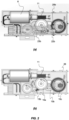
- a manual actuator 30 is provided to rotate the locking ring 12b back to its unlocked position (e.g. counter-clock wise) via a locking ring lever 28.
- a unidirectional clutch mechanism 34 is provided with the coupling between the gear 10c and the coaxially arranged locking ring 12b.
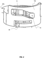
- the clutch mechanism 34 comprises a plurality of apertures or cavities 36 that are circumferentially equidistantly arranged on an inner surface of gear 10c (see Figure 6(b) ) and at least two resilient tooth members 38 provided within the cylindrical wall of the locking ring 12b.
- the resilient tooth members 38 are arranged so as to operably engage with the apertures or cavities 36, i.e. the resilient tooth members 38 can slidably move from one aperture or cavity 36 to another in one direction (e.g. counter-clockwise), while the gears remain stationary, but lockingly engage with any one of the apertures or cavities 36 in the opposite direction (e.g. clockwise), thus rotating with the locking ring 12b.
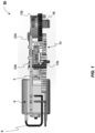
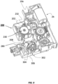
- the door locking module 2b is further provided with a housing 26 adapted to operably accommodate at least the component parts, such as, the PCB 4, motor 6 and wires 8, gear mechanism 10, locking ring 12b, door sensing pin 13b and locking pin 16.
- the electric motor 6 is actuated or energised so that the output shaft of the electric motor 6 and the attached worm gear shaft 11 rotate in a desired direction.
- the worm gear shaft 11 engages gear 10a, which in turn engages gear 10b to then engage gear 10c and rotating the locking ring 12b.
- the directions of rotation are indicated by arrows on respective gears 10a, 10b, 10c.
- the actuation of the electric motor 6 drives the locking ring 12b via gear mechanism 10 either clockwise or counter-clockwise.
- the rotational motion of the motor 6 is transferred onto the locking ring 12b via coupled gear 10c.
- Rotation of the locking ring 12b changes the position of the cam guide 14 relative to the engaged cam follower 18 of the locking pin 16, thus, axially moving the locking pin 16 between the locked and unlocked position.
- the cam follower 18 is positioned at a first end (left end or upper end) of the cam guide 14, causing the locking pin 16 to be moved up (unlocked from the appliance door).
- the cam follower 18 When the locking ring 12b is rotated clockwise, the cam follower 18 is positioned at the second end (right end or lower end) of the cam guide 14, causing the locking pin 16 to be moved down (locking the appliance door). Since the electric motor 6 is drivable bidirectionally (i.e. clockwise and counter-clockwise), it is possible to control the position of the locking pin 16 via motor control.
- integrating the actuator or sensor 22b with the PCB 4, so as to cooperate with the trigger member 20b allows the use of PCB's 4 with reduced dimensions (compared to present locking modules), because the position of the locking pin 16 is sensed directly from the position of the locking ring 12b.
- the clutch mechanism 34 is used to provide a manual unlock function of the appliance door that is decoupled from the gear mechanism 10.
- the actuator arm 32 of the manual actuator 30 is pushed into engagement with the locking ring lever 28, thus, rotating the locking ring 12b counter-clockwise relative to a stationary gear 10c, with the tooth member(s) 38 sliding through the apertures 36.
- This decoupled rotation of the locking ring 12b moves the locking pin 16 into the unlocked position.
- the automatic opening module 200 is particularly suitable for use with a door-locking module 2b, as described in section (a), so as to form a door-locking system of a household appliance.
- a door-locking module 2b as described in section (a)
- the automatic opening module 200 may also be used with any other suitable door-locking mechanisms or household appliances.
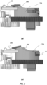
- the automatic opening module 200 includes a housing 202.
- the housing 202 is generally cuboid, having four outer walls, a lower face or base and an upper face within which a hollow is defined.
- the housing 202 includes a top or upper housing cover 204 and a bottom or lower housing portion 206.
- the upper housing cover 204 includes the upper face of the housing 202 and one or more walls which form part of one or more of the outer walls of the housing 202.
- the lower housing portion 206 includes the base of the housing 202 and one or more walls which form part of one of more of the outer walls of the housing 202.
- the housing 202 also includes a first opening 208 and a second opening 210. Each of the first opening 208 and the second opening 210 are defined between the one or more walls of the upper housing cover 204 and the one or more walls of the lower housing portion 206.
- a first catch portion 212 is provided on the upper housing cover 204 on the upper face of the housing 202.
- the lower housing portion 206 includes a flange 214, which extends from one of the walls which form part of one of the outer walls of the housing 202, and a respective protrusions or teeth 216 adapted to lockingly engage with the upper housing cover 204.
- a second catch portion 218 is provided on an outer surface the flange 214 (i.e. the second catch portion 218 is provided on a surface of the flange which faces away from the hollow within the housing 202).
- a first shaft 220 and a second shaft 222 extend upwardly from the lower housing portion 206 (i.e. the first shaft 220 and the second shaft 222 extend from the base of the housing 202 into the hollow within the housing 202).
- a rib 224 extends inwardly from one of the walls of the lower housing portion 206, as illustrated in Figure 12 .
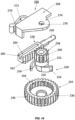
- the automatic opening module 200 also includes a transmission mechanism 226 and a lever engaging pin 228.
- the transmission mechanism 226 includes a first part, which is operably coupled to the lever engaging pin 228, and a second part, which is configured to operably engage with an actuator of a door locking module, for example, the gear member 10e (of gear assembly 10) and the electric motor 6 of the door locking module 2b.
- the transmission mechanism 226 is a gear assembly including a plurality of gears.
- the first part of the transmission mechanism 226 includes a first gear 230 and the second part of the transmission mechanism 226 includes a second gear 232.
- the first gear 230 includes a first gear member 234 having a plurality of outer teeth 236 and the second gear member 238 having a plurality of outer teeth 240.
- the second gear member 238 is operably coupled to and coaxially arranged with the first gear member 234 such that the second gear member 238 and the first gear member 234 rotate together.
- the diameter of the first gear member 234 is greater than the diameter of the second gear member 238.
- the second gear 232 includes a first gear member 242 having a plurality of outer teeth 244 and a second gear member 246 having a plurality of outer teeth 248.
- the second gear member 246 is coaxial with the first gear member 242, and the first and second gear members 242, 246 are integral parts.
- the diameter of the first gear member 242 is greater than the diameter of the second gear member 246.
- the gear ratios between the respective engaging gears 230, 232 are chosen so that a given motor rotation provides a suitable linear movement of the lever engaging pin 228 (described in more detail below).
- the first gear 230 incorporates a clutch mechanism 250 operably coupling the first and second gear member 234, 238 of the first gear 230.
- the clutch mechanism 250 includes a clutch ring 252, having two or more resilient tooth members 254 extending radially outward, and a plurality of apertures or cavities 256 that are circumferentially equidistantly arranged on an inner surface of the first gear member 234.
- the resilient tooth members 254 are arranged so as to operably engage with the apertures or cavities 256, i.e. the resilient tooth members 254 can slidably move from one aperture or cavity 256 to another in one direction (e.g. -clockwise) while the first and second gears 230, 232 remain stationary, but lockingly engage with any one of the apertures or cavities 256 in the opposite direction (e.g. counter-clockwise), thus rotating with the clutch ring 252.
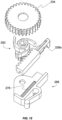
- the lever engaging pin 228 is an elongate body that has a pin portion 258 at a distal end and a rack gear portion 260 at a proximal end (inside the housing).
- the rack gear portion 260 includes a plurality of teeth 262, which extend along one edge of the rack gear portion 260, and a slot 264, which extends along one surface of the rack gear portion 260 (open towards the proximal end).
- the automatic opening module 200 also includes a reset lever 266 (see also Figures 14 and 15 ).
- the reset lever 266 has a body 268 and a resilient arm 270.
- An opening 272 is defined between the body 268 and the resilient arm 270 of the reset lever 266.
- the body 268 includes a flange 274 through which an aperture 276 extends, and an elongate slider 278 which extends along the length of the body 268.
Landscapes
- Engineering & Computer Science (AREA)
- Textile Engineering (AREA)
- Physics & Mathematics (AREA)
- Electromagnetism (AREA)
- Lock And Its Accessories (AREA)
Claims (12)
- Automatisches Öffnungsmodul (200) für eine Tür eines Haushaltsgeräts, das automatische Öffnungsmodul (200) aufweisend:ein Gehäuse (202);ein Übertragungssystem (226); undeinen Hebeleingriffsstift (228), der einen Zahnstangenabschnitt (260) aufweist;wobei das Übertragungssystem (226) eine Zahnradbaugruppe ist, die eine Vielzahl von Zahnrädern aufweist;wobei das Übertragungssystem (226) und der Hebeleingriffsstift (228) innerhalb des Gehäuses (202) aufgenommen sind;wobei ein erster Teil des Übertragungssystems (226) ein erstes Zahnrad (230) der Vielzahl von Zahnrädern aufweist und ein zweiter Teil des Übertragungssystems (226) ein zweites Zahnrad (232) der Vielzahl von Zahnrädern aufweist;wobei der erste Teil des Übertragungssystems (226) mit dem Zahnstangenabschnitt (260) des Hebeleingriffsstifts (228) betriebsfähig gekoppelt ist; undwobei der zweite Teil des Übertragungssystems (226) so ausgebildet ist, dass er mit einem Aktor eines Türverriegelungsmoduls betriebsfähig in Eingriff kommt, sodass im Betrieb die Betätigung des Aktors bewirkt, dass das Übertragungssystem (226) den Hebeleingriffsstift (228) zwischen einer ersten, verriegelten Position und einer zweiten, entriegelten Position bewegt.
- Automatisches Öffnungsmodul (200) nach Anspruch 1, wobei der Hebeleingriffsstift (228), wenn er sich in der ersten, verriegelten Position befindet, in das Gehäuse (202) des automatischen Öffnungsmoduls (200) bewegt wird, und, wenn er sich in der zweiten, entriegelten Position befindet, mindestens ein Teil des Hebeleingriffsstifts (228) aus dem Gehäuse (202) des automatischen Öffnungsmoduls (200) bewegt wird.
- Automatisches Öffnungsmodul (200) nach einem der vorhergehenden Ansprüche, wobei der erste Teil des Übertragungssystems (226) einen Kupplungsmechanismus (250) aufweist.
- Automatisches Öffnungsmodul (200) nach Anspruch 3, wobei der Kupplungsmechanismus (250) einen Kupplungsring (252) aufweist, der mindestens zwei elastische Zahnelemente (254) aufweist.
- Automatisches Öffnungsmodul (200) nach Anspruch 4, wobei der Kupplungsmechanismus (250) eine Vielzahl von Öffnungen (256) aufweist, die an einer Innenfläche des ersten Teils des Übertragungssystems (226) angeordnet sind.
- Automatisches Öffnungsmodul (200) nach einem der Ansprüche 3 bis 5, das einen Rückstellhebel (266) aufweist.
- Automatisches Öffnungsmodul (200) nach Anspruch 6, wobei der Rückstellhebel (266) gleitend mit dem Hebeleingriffsstift (228) in Eingriff steht.
- Automatisches Öffnungsmodul (200) nach Anspruch 6 oder Anspruch 7, wobei der Rückstellhebel (266) einen Körper (268) und einen elastischen Arm (270) aufweist; und wobei eine Öffnung (272) zwischen dem Körper (268) und dem elastischen Arm (270) definiert ist.
- Automatisches Öffnungsmodul (200) nach Anspruch 8, wobei das Gehäuse (202) einen Vorsprung (224) aufweist, der sich von einer Innenwand des Gehäuses (202) erstreckt.
- Automatisches Öffnungsmodul (200) nach Anspruch 9, wobei die Öffnung (272) des Rückstellhebels (266) so ausgebildet ist, dass sie den Vorsprung (224) des Gehäuses (202) aufnimmt.
- Automatisches Öffnungsmodul (200) nach einem der Ansprüche 1 bis 10, wobei das Gehäuse (202) eine erste Öffnung (208) aufweist, durch die sich zumindest ein Abschnitt des Hebeleingriffsstifts (228) erstreckt.
- Automatisches Öffnungsmodul (200) nach Anspruch 11, wobei das Gehäuse (202) eine zweite Öffnung (210) aufweist, durch die sich zumindest ein Abschnitt des zweiten Zahnrads (232) erstreckt, um betriebsfähig mit einem Aktor eines Türverriegelungsmoduls in Eingriff zu kommen.
Priority Applications (3)
| Application Number | Priority Date | Filing Date | Title |
|---|---|---|---|
| US19/110,653 US20260022588A1 (en) | 2022-09-19 | 2023-09-19 | Automated opening module for a door of a household appliance |
| PCT/US2023/033136 WO2024064132A1 (en) | 2022-09-19 | 2023-09-19 | Automatic opening module for a door of a household appliance |
| CN202380066655.6A CN119923502A (zh) | 2022-09-19 | 2023-09-19 | 用于家用电器的门的自动打开模块 |
Applications Claiming Priority (2)
| Application Number | Priority Date | Filing Date | Title |
|---|---|---|---|
| EP22196421 | 2022-09-19 | ||
| EP23172899 | 2023-05-11 |
Publications (2)
| Publication Number | Publication Date |
|---|---|
| EP4339353A1 EP4339353A1 (de) | 2024-03-20 |
| EP4339353B1 true EP4339353B1 (de) | 2025-07-02 |
Family
ID=88018158
Family Applications (1)
| Application Number | Title | Priority Date | Filing Date |
|---|---|---|---|
| EP23198038.4A Active EP4339353B1 (de) | 2022-09-19 | 2023-09-18 | Automatisches öffnungsmodul für eine tür eines haushaltsgeräts |
Country Status (2)
| Country | Link |
|---|---|
| EP (1) | EP4339353B1 (de) |
| PL (1) | PL4339353T3 (de) |
Families Citing this family (1)
| Publication number | Priority date | Publication date | Assignee | Title |
|---|---|---|---|---|
| DE102024107497B4 (de) * | 2024-03-15 | 2026-02-12 | Emz-Hanauer Gmbh & Co. Kgaa | Türöffner für ein elektrisches Haushaltsgerät |
Family Cites Families (3)
| Publication number | Priority date | Publication date | Assignee | Title |
|---|---|---|---|---|
| CN207960222U (zh) | 2016-07-06 | 2018-10-12 | 伊利诺斯工具制品有限公司 | 门锁 |
| IT201800002107A1 (it) * | 2018-01-29 | 2019-07-29 | Illinois Tool Works | Modulo interruttore di blocco motorizzato per un blocco-porta per elettrodomestici |
| US20210238888A1 (en) * | 2020-01-31 | 2021-08-05 | Bitron S.P.A. | Door-lock device and household appliance equipped with such door-lock device |
-
2023
- 2023-09-18 EP EP23198038.4A patent/EP4339353B1/de active Active
- 2023-09-18 PL PL23198038.4T patent/PL4339353T3/pl unknown
Also Published As
| Publication number | Publication date |
|---|---|
| EP4339353A1 (de) | 2024-03-20 |
| PL4339353T3 (pl) | 2025-11-12 |
Similar Documents
| Publication | Publication Date | Title |
|---|---|---|
| EP2450510B1 (de) | Türverriegelungsvorrichtung für Haushaltsgerät und bistabiler Mechanismus | |
| FI79589C (fi) | Laosanordning. | |
| CN108699858B (zh) | 机电式锁定闩 | |
| EP4339353B1 (de) | Automatisches öffnungsmodul für eine tür eines haushaltsgeräts | |
| WO2016036947A1 (en) | Lock drive assemblies | |
| EP3307132B1 (de) | System zur steuerung des schliessens einer tür eines haushaltsgeräts, insbesondere für eine waschmaschine, wie etwa ein geschirrspüler | |
| CN117661928A (zh) | 锁定装置 | |
| US20260022588A1 (en) | Automated opening module for a door of a household appliance | |
| EP1498796B1 (de) | Betätigungs- und/oder Verriegelungsvorrichtung für Haushaltsgeräte mit verbessertem System zur Steuerung der Betätigungsvorrichtung | |
| KR20180114861A (ko) | 레버형 도어락의 클러치 연결 구동 조립체 | |
| JP2008190193A (ja) | 錠装置 | |
| EP4339403B1 (de) | Türverriegelungsmodul für eine tür eines haushaltsgeräts | |
| US12366094B2 (en) | Electronic striker for releasing a compartment door and method of using the same | |
| CN112217054B (zh) | 一种直流充电枪电子锁与直流充电枪 | |
| EP4423329B1 (de) | Verbessertes türschloss für ein haushaltsgerät | |
| US12320155B2 (en) | Locking device for mechanical and non-mechanical activation of a locking bolt | |
| JP2008190187A (ja) | 錠装置 | |
| CN118435306A (zh) | 双电源转换开关 | |
| KR102318848B1 (ko) | 도어락의 클러치 모듈조립체 | |
| CN211448149U (zh) | 一种全自动锁体 | |
| CN110886543B (zh) | 用于门配件的联接装置、门配件系统和用于联接装置的联接或断开联接的方法 | |
| CN221373235U (zh) | 一种智能柜门锁 | |
| EP4204650B1 (de) | Anordnung für eine schlossvorrichtung und schlossvorrichtung mit anordnung | |
| CN110566050A (zh) | 一种全自动锁体 | |
| CN119802055A (zh) | 自动锁止装置 |
Legal Events
| Date | Code | Title | Description |
|---|---|---|---|
| PUAI | Public reference made under article 153(3) epc to a published international application that has entered the european phase |
Free format text: ORIGINAL CODE: 0009012 |
|
| STAA | Information on the status of an ep patent application or granted ep patent |
Free format text: STATUS: THE APPLICATION HAS BEEN PUBLISHED |
|
| AK | Designated contracting states |
Kind code of ref document: A1 Designated state(s): AL AT BE BG CH CY CZ DE DK EE ES FI FR GB GR HR HU IE IS IT LI LT LU LV MC ME MK MT NL NO PL PT RO RS SE SI SK SM TR |
|
| STAA | Information on the status of an ep patent application or granted ep patent |
Free format text: STATUS: REQUEST FOR EXAMINATION WAS MADE |
|
| 17P | Request for examination filed |
Effective date: 20240913 |
|
| RBV | Designated contracting states (corrected) |
Designated state(s): AL AT BE BG CH CY CZ DE DK EE ES FI FR GB GR HR HU IE IS IT LI LT LU LV MC ME MK MT NL NO PL PT RO RS SE SI SK SM TR |
|
| REG | Reference to a national code |
Ref country code: DE Ref legal event code: R079 Free format text: PREVIOUS MAIN CLASS: D06F0039140000 Ipc: E05B0001000000 Ref document number: 602023004481 Country of ref document: DE |
|
| GRAP | Despatch of communication of intention to grant a patent |
Free format text: ORIGINAL CODE: EPIDOSNIGR1 |
|
| STAA | Information on the status of an ep patent application or granted ep patent |
Free format text: STATUS: GRANT OF PATENT IS INTENDED |
|
| RIC1 | Information provided on ipc code assigned before grant |
Ipc: E05B 47/00 20060101ALN20250217BHEP Ipc: E05B 17/00 20060101ALN20250217BHEP Ipc: E05B 47/02 20060101ALI20250217BHEP Ipc: D06F 39/14 20060101ALI20250217BHEP Ipc: A47L 15/42 20060101ALI20250217BHEP Ipc: E05B 1/00 20060101AFI20250217BHEP |
|
| INTG | Intention to grant announced |
Effective date: 20250227 |
|
| GRAS | Grant fee paid |
Free format text: ORIGINAL CODE: EPIDOSNIGR3 |
|
| GRAA | (expected) grant |
Free format text: ORIGINAL CODE: 0009210 |
|
| STAA | Information on the status of an ep patent application or granted ep patent |
Free format text: STATUS: THE PATENT HAS BEEN GRANTED |
|
| P01 | Opt-out of the competence of the unified patent court (upc) registered |
Free format text: CASE NUMBER: APP_20523/2025 Effective date: 20250429 |
|
| AK | Designated contracting states |
Kind code of ref document: B1 Designated state(s): AL AT BE BG CH CY CZ DE DK EE ES FI FR GB GR HR HU IE IS IT LI LT LU LV MC ME MK MT NL NO PL PT RO RS SE SI SK SM TR |
|
| REG | Reference to a national code |
Ref country code: GB Ref legal event code: FG4D |
|
| REG | Reference to a national code |
Ref country code: CH Ref legal event code: EP |
|
| REG | Reference to a national code |
Ref country code: DE Ref legal event code: R096 Ref document number: 602023004481 Country of ref document: DE |
|
| REG | Reference to a national code |
Ref country code: IE Ref legal event code: FG4D |
|
| PGFP | Annual fee paid to national office [announced via postgrant information from national office to epo] |
Ref country code: AT Payment date: 20251020 Year of fee payment: 3 |
|
| REG | Reference to a national code |
Ref country code: NL Ref legal event code: MP Effective date: 20250702 |
|
| PG25 | Lapsed in a contracting state [announced via postgrant information from national office to epo] |
Ref country code: PT Free format text: LAPSE BECAUSE OF FAILURE TO SUBMIT A TRANSLATION OF THE DESCRIPTION OR TO PAY THE FEE WITHIN THE PRESCRIBED TIME-LIMIT Effective date: 20251103 |
|
| PG25 | Lapsed in a contracting state [announced via postgrant information from national office to epo] |
Ref country code: NL Free format text: LAPSE BECAUSE OF FAILURE TO SUBMIT A TRANSLATION OF THE DESCRIPTION OR TO PAY THE FEE WITHIN THE PRESCRIBED TIME-LIMIT Effective date: 20250702 |
|
| REG | Reference to a national code |
Ref country code: AT Ref legal event code: MK05 Ref document number: 1809417 Country of ref document: AT Kind code of ref document: T Effective date: 20250702 |
|
| PG25 | Lapsed in a contracting state [announced via postgrant information from national office to epo] |
Ref country code: IS Free format text: LAPSE BECAUSE OF FAILURE TO SUBMIT A TRANSLATION OF THE DESCRIPTION OR TO PAY THE FEE WITHIN THE PRESCRIBED TIME-LIMIT Effective date: 20251102 |
|
| PGFP | Annual fee paid to national office [announced via postgrant information from national office to epo] |
Ref country code: DE Payment date: 20251029 Year of fee payment: 3 |
|
| PG25 | Lapsed in a contracting state [announced via postgrant information from national office to epo] |
Ref country code: NO Free format text: LAPSE BECAUSE OF FAILURE TO SUBMIT A TRANSLATION OF THE DESCRIPTION OR TO PAY THE FEE WITHIN THE PRESCRIBED TIME-LIMIT Effective date: 20251002 |
|
| REG | Reference to a national code |
Ref country code: LT Ref legal event code: MG9D |
|
| PG25 | Lapsed in a contracting state [announced via postgrant information from national office to epo] |
Ref country code: AT Free format text: LAPSE BECAUSE OF FAILURE TO SUBMIT A TRANSLATION OF THE DESCRIPTION OR TO PAY THE FEE WITHIN THE PRESCRIBED TIME-LIMIT Effective date: 20250702 |
|
| PG25 | Lapsed in a contracting state [announced via postgrant information from national office to epo] |
Ref country code: FI Free format text: LAPSE BECAUSE OF FAILURE TO SUBMIT A TRANSLATION OF THE DESCRIPTION OR TO PAY THE FEE WITHIN THE PRESCRIBED TIME-LIMIT Effective date: 20250702 |
|
| PGFP | Annual fee paid to national office [announced via postgrant information from national office to epo] |
Ref country code: IT Payment date: 20250930 Year of fee payment: 3 |
|
| PG25 | Lapsed in a contracting state [announced via postgrant information from national office to epo] |
Ref country code: HR Free format text: LAPSE BECAUSE OF FAILURE TO SUBMIT A TRANSLATION OF THE DESCRIPTION OR TO PAY THE FEE WITHIN THE PRESCRIBED TIME-LIMIT Effective date: 20250702 |
|
| PG25 | Lapsed in a contracting state [announced via postgrant information from national office to epo] |
Ref country code: GR Free format text: LAPSE BECAUSE OF FAILURE TO SUBMIT A TRANSLATION OF THE DESCRIPTION OR TO PAY THE FEE WITHIN THE PRESCRIBED TIME-LIMIT Effective date: 20251003 |
|
| PGFP | Annual fee paid to national office [announced via postgrant information from national office to epo] |
Ref country code: TR Payment date: 20251007 Year of fee payment: 3 |
|
| PG25 | Lapsed in a contracting state [announced via postgrant information from national office to epo] |
Ref country code: CZ Free format text: LAPSE BECAUSE OF FAILURE TO SUBMIT A TRANSLATION OF THE DESCRIPTION OR TO PAY THE FEE WITHIN THE PRESCRIBED TIME-LIMIT Effective date: 20250702 Ref country code: SE Free format text: LAPSE BECAUSE OF FAILURE TO SUBMIT A TRANSLATION OF THE DESCRIPTION OR TO PAY THE FEE WITHIN THE PRESCRIBED TIME-LIMIT Effective date: 20250702 |
|
| PG25 | Lapsed in a contracting state [announced via postgrant information from national office to epo] |
Ref country code: LV Free format text: LAPSE BECAUSE OF FAILURE TO SUBMIT A TRANSLATION OF THE DESCRIPTION OR TO PAY THE FEE WITHIN THE PRESCRIBED TIME-LIMIT Effective date: 20250702 |
|
| PG25 | Lapsed in a contracting state [announced via postgrant information from national office to epo] |
Ref country code: BG Free format text: LAPSE BECAUSE OF FAILURE TO SUBMIT A TRANSLATION OF THE DESCRIPTION OR TO PAY THE FEE WITHIN THE PRESCRIBED TIME-LIMIT Effective date: 20250702 |
|
| PG25 | Lapsed in a contracting state [announced via postgrant information from national office to epo] |
Ref country code: RS Free format text: LAPSE BECAUSE OF FAILURE TO SUBMIT A TRANSLATION OF THE DESCRIPTION OR TO PAY THE FEE WITHIN THE PRESCRIBED TIME-LIMIT Effective date: 20251002 |
|
| PG25 | Lapsed in a contracting state [announced via postgrant information from national office to epo] |
Ref country code: ES Free format text: LAPSE BECAUSE OF FAILURE TO SUBMIT A TRANSLATION OF THE DESCRIPTION OR TO PAY THE FEE WITHIN THE PRESCRIBED TIME-LIMIT Effective date: 20250702 |