EP4339151A1 - A multifunctional lifting vehicle designed to determine a load diagram, and relative method - Google Patents
A multifunctional lifting vehicle designed to determine a load diagram, and relative method Download PDFInfo
- Publication number
- EP4339151A1 EP4339151A1 EP23197195.3A EP23197195A EP4339151A1 EP 4339151 A1 EP4339151 A1 EP 4339151A1 EP 23197195 A EP23197195 A EP 23197195A EP 4339151 A1 EP4339151 A1 EP 4339151A1
- Authority
- EP
- European Patent Office
- Prior art keywords
- equipment
- vehicle
- piece
- new
- load
- Prior art date
- Legal status (The legal status is an assumption and is not a legal conclusion. Google has not performed a legal analysis and makes no representation as to the accuracy of the status listed.)
- Pending
Links
Images





Classifications
-
- B—PERFORMING OPERATIONS; TRANSPORTING
- B66—HOISTING; LIFTING; HAULING
- B66F—HOISTING, LIFTING, HAULING OR PUSHING, NOT OTHERWISE PROVIDED FOR, e.g. DEVICES WHICH APPLY A LIFTING OR PUSHING FORCE DIRECTLY TO THE SURFACE OF A LOAD
- B66F17/00—Safety devices, e.g. for limiting or indicating lifting force
- B66F17/003—Safety devices, e.g. for limiting or indicating lifting force for fork-lift trucks
-
- B—PERFORMING OPERATIONS; TRANSPORTING
- B66—HOISTING; LIFTING; HAULING
- B66F—HOISTING, LIFTING, HAULING OR PUSHING, NOT OTHERWISE PROVIDED FOR, e.g. DEVICES WHICH APPLY A LIFTING OR PUSHING FORCE DIRECTLY TO THE SURFACE OF A LOAD
- B66F9/00—Devices for lifting or lowering bulky or heavy goods for loading or unloading purposes
- B66F9/06—Devices for lifting or lowering bulky or heavy goods for loading or unloading purposes movable, with their loads, on wheels or the like, e.g. fork-lift trucks
- B66F9/065—Devices for lifting or lowering bulky or heavy goods for loading or unloading purposes movable, with their loads, on wheels or the like, e.g. fork-lift trucks non-masted
- B66F9/0655—Devices for lifting or lowering bulky or heavy goods for loading or unloading purposes movable, with their loads, on wheels or the like, e.g. fork-lift trucks non-masted with a telescopic boom
-
- B—PERFORMING OPERATIONS; TRANSPORTING
- B66—HOISTING; LIFTING; HAULING
- B66F—HOISTING, LIFTING, HAULING OR PUSHING, NOT OTHERWISE PROVIDED FOR, e.g. DEVICES WHICH APPLY A LIFTING OR PUSHING FORCE DIRECTLY TO THE SURFACE OF A LOAD
- B66F9/00—Devices for lifting or lowering bulky or heavy goods for loading or unloading purposes
- B66F9/06—Devices for lifting or lowering bulky or heavy goods for loading or unloading purposes movable, with their loads, on wheels or the like, e.g. fork-lift trucks
- B66F9/075—Constructional features or details
- B66F9/07581—Remote controls
-
- G—PHYSICS
- G06—COMPUTING OR CALCULATING; COUNTING
- G06F—ELECTRIC DIGITAL DATA PROCESSING
- G06F3/00—Input arrangements for transferring data to be processed into a form capable of being handled by the computer; Output arrangements for transferring data from processing unit to output unit, e.g. interface arrangements
- G06F3/01—Input arrangements or combined input and output arrangements for interaction between user and computer
- G06F3/048—Interaction techniques based on graphical user interfaces [GUI]
- G06F3/0481—Interaction techniques based on graphical user interfaces [GUI] based on specific properties of the displayed interaction object or a metaphor-based environment, e.g. interaction with desktop elements like windows or icons, or assisted by a cursor's changing behaviour or appearance
- G06F3/0482—Interaction with lists of selectable items, e.g. menus
Definitions
- the present invention relates to a multifunctional lifting vehicle comprising
- a vehicle of the type indicated above is disclosed for example in document EP 3 889 096 A1 .
- the vehicle may be equipped with different types of equipment, such as forks, shovels, aerial platforms, etc.
- the load applied to the piece of equipment located at the end of the telescopic arm can vary widely.
- multifunctional lifting vehicles are equipped with a load diagram which indicates the maximum load that can be applied to the end of the lifting arm according to the position of the equipment. Compliance with the load diagram is the responsibility of the operator, who must have optimal training and knowledge of the vehicle, and must know the limits of the effective working range of the arm, according to the load applied to the equipment each time.
- One of the key safety aspects of a lifting vehicle is its longitudinal rollover stability.
- Vehicles with lifting arms are equipped with an anti-rollover safety system, which stops movement of the lifting arm of the vehicle, when the stability limit is reached. In some known solutions, this occurs when the load on the rear supports drops below a pre-set reference threshold. In fact, reduction of the load on the rear axle below a critical threshold indicates that the vehicle is close to overturning.
- the need for a load diagram, in graphical or tabular form, is a peculiarity of lifting machines, the capacity of which may vary according to the spatial positioning of the lifting means and the load lifted, as well as its size, or other elements concerning a specific operating configuration of the vehicle itself.
- the capacity of which may vary according to the spatial positioning of the lifting means and the load lifted, as well as its size, or other elements concerning a specific operating configuration of the vehicle itself.
- the extension and shape of the support plant and the speed of movement it is also necessary to consider the specific equipment installed.
- equipment quantities and associated load diagrams are originally determined by the vehicle manufacturer.
- the user wishes to install a new type of equipment not included among those originally approved by the manufacturer, it is necessary to request subsequent authorization from the vehicle manufacturer.
- This situation is particularly disadvantageous in the case of vehicles equipped with automatic recognition of the connected equipment, since it becomes necessary to request modifications to the vehicle control system to allow correct use by the operator. Since these types of interventions are carried out after the vehicle has been placed on the market, they have a considerable impact in terms of costs and implementation times.
- the vehicle manufacturer may refuse to approve equipment for technical or logistical reasons for sourcing the equipment or for commercial reasons.
- the object of the present invention is to propose a lifting vehicle and a relative method for overcoming the problems indicated above.
- numeral 1 indicates a lifting vehicle comprising a fixed self-propelled frame 2 having front supports 3 and rear supports 4 on wheels.
- the vehicle 1 comprises a telescopic arm 5 articulated in the rear section of the frame 2 about a transverse axis 6.
- the telescopic arm 5 is provided at one end with a connection 7 for connecting equipment 8 of different types.
- Figure 2 comprises an example of piece of equipment 8, in particular a fork shifter, connected to the telescopic arm 5.
- the vehicle 1 comprises a drive system configured to operate the telescopic arm 5 carrying the aforesaid piece of equipment 8.
- the drive system comprises at least one lifting/lowering cylinder 9 with ends articulated to the frame 2 and to the arm 5 about the respective axes 10, 11.
- the arm 5 is also equipped with a cylinder (not shown), which controls the telescopic extension and retraction movement of the arm 5.
- the drive system may further comprise a hydraulic drive circuit including a main pump driven by a motor of the vehicle 1. The details relating to the hydraulic circuit are not described here, as they are widely known to the expert in the field in question.
- FIGs 3, 4 illustrate a lifting vehicle 1 comprising a self-propelled frame 2 rotating with front and rear supports 3, 4 on stabilizers.
- the components of the vehicle 1 are indicated with the same references indicated above for the vehicle with fixed frame of Figure 1 . It should, therefore, be noted that the present invention is equally applicable to a lifting vehicle with a fixed or rotating frame 2, both on wheels and on stabilizers.
- FIG. 5 is a simplified diagram showing a control system 12 associated with the drive system of the vehicle 1.
- the control system 12 is arranged to control, among other things, respective operating valves of the hydraulic circuit.
- the control system 12 comprises a load sensor 13, which provides an indication of the intensity of the load applied to the arm 5.
- the load sensor 13 may, for example, be a load cell applied to the lifting/lowering cylinder 9.
- the control system 12 also comprises sensors 14, 15 which detect, respectively, the inclination angle ⁇ of the arm 5 and the extension length L of the telescopic portion of the arm 5.
- the control system 12 further comprises one or more sensors 16 to detect the load on the supports 3 and/or 4 of the vehicle 1 and possibly other sensors 16' present on the vehicle 1 to detect, for example, the extension of the stabilizers and the rotation angle of an upper frame.
- the control system 12 also comprises a recognition unit 17 configured for recognizing the type of equipment 8 applied to the arm 5.
- the recognition unit 17 may, for example, be based on RFID technology.
- the control system 12 comprises an electronic control unit E programmed to independently define a load diagram of the vehicle 1 according to the type of equipment 8, if the connected equipment 8 is part of a set of predetermined equipment stored within a memory associated with the control system 12.
- the control system 12 is configured to determine the load diagram relating to the connected equipment 8, provided that the equipment 8 has been recognized.
- the electronic control unit E receives the signals coming from the sensors 13, 14, 15, 16, from the recognition unit 17, plus any information coming from other sensors 16' possibly present on the vehicle 1.
- the vehicle 1 comprises a human-machine interface device 18, through which the user can manage all the operations of the vehicle 1.
- the human-machine interface device 18 may be a fixed screen inside the cabin of the vehicle 1, or a removable screen.
- the human-machine interface device 18 may comprise control devices, such as push-button panels, or a tactile screen (touch screen) or a combination of the two.
- control system 12 of the vehicle 1 is configured to determine a load diagram of the vehicle 1, even in the case where the connected equipment 8 is an "unknown" piece of equipment, i.e. not originally approved by the manufacturer of the vehicle 1, and therefore not included in the memorized set of predetermined equipment.
- the electronic control unit E is programmed for:
- the user may manually introduce into the control system 12 various identification parameters necessary to identify the characteristics of the connected piece of equipment 8, useful for determining the new load diagram.
- the aforesaid functional parameters of the new piece of equipment 8 comprise:
- the aforesaid parameters may also be entered using a mobile device (such as a tablet or smartphone) or an electronic processor, possibly used from a remote location. Thanks to this characteristic, it is possible to manually enter the operating parameters of the new piece of equipment 8 from a remote station, subject to authentication by the user.
- the interface menu for entering the aforesaid parameters described above allows the setting and storage of different profiles of respective authorized users.
- the control system 12 is, therefore, configured to verify the user's identity by entering personal credentials (username and password) or by using a dedicated physical device, such as, for example, a key or magnetic card.
- the control system 12 is therefore arranged to admit or deny access to the operating modes for configuring the load diagram.
- control system 12 comprises a module for wireless local connection which allows an authorized user to access the control system 12 for various operations such as, for example, updating the set of stored equipment 8.
- the electronic control unit E may also be programmed to download different configurations of a given piece of equipment 8 from a specific Internet domain.
- control system 12 automatically calculates the new load diagram relating to the connected piece of equipment 8, to then be displayed on the screen of the human-machine interface device 18.
- Process means associated with the electronic control unit E are programmed and configured to receive and process the functional parameters entered by the user, with a view to calculating the new load diagram for each new piece of equipment 8 connected.
- the process means are also programmed to memorize the functional parameters previously entered for each new "unknown" piece of equipment 8 connected.
- the process means are furthermore programmed to calculate the load diagrams, in case the new piece of equipment 8 is connected again after the use of the vehicle 1 with other equipment 8.
- the calculation of the new load diagram is performed by means of the same algorithm implemented to calculate the diagrams relating to equipment 8 already recognized and stored.
- control system 12 is configured to limit the operation of the vehicle 1, so that the operation is constrained within the limits determined by the new load diagram.
- the human-machine interface device 18 may have a selection menu arranged to select this limited operating mode.
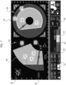
- the human-machine interface device 18 displays a working area panel 19 with representation of a load diagram showing working areas according to a side view 20 and a plan view 21.
- the drawings of Figure 7 are provided purely by way of example in order to understand qualitatively the operation of the system according to the invention.
- working area means the definition of a safe operating space, having known the load on the equipment and the type of equipment. Consequently, in the case of a new unrecognized piece of equipment 8, the working areas may be correctly displayed by recalling the previously stored functional parameters for the piece of equipment 8.
- the load diagram comprises working areas 20, 21 define respective sub-areas 22, 23, 24 which respectively subdivide the diagram into:
- some operating parameters are also displayed, including:
- auxiliary interaction window 31 which displays further operating conditions of the vehicle 1, including:
- Figure 8 illustrates an operating screen 35 of the human-machine interface device 18 which displays a menu for manual entry of the identification parameters necessary to identify the characteristics of an "unknown" piece of connected equipment 8, useful for determining the new load diagram and the new working areas.
- the aforesaid parameters of the new piece of equipment 8 include various characteristic parameters of the piece of equipment 8, such as, for example, the weight, the position of the center of gravity, the maximum capacity and the position of the load center; further optional parameters such as, for example, a parameter expressed as a percentage reduction coefficient or as an additional safety factor.
- Figure 9 reports a further operating screen 36 of the human-machine interface device 18 which displays the load diagram processed on the basis of the parameters previously entered and the information received from the sensors 13,14,15,16,16'.
- the diagrams are represented according to a side view 37 and a plan view 38.
- References 39,40,41,42,43 indicate different capacity ranges of the load diagram according to the side view 37 and plan view 38.
Landscapes
- Engineering & Computer Science (AREA)
- Structural Engineering (AREA)
- Transportation (AREA)
- Mechanical Engineering (AREA)
- Life Sciences & Earth Sciences (AREA)
- Geology (AREA)
- Civil Engineering (AREA)
- General Engineering & Computer Science (AREA)
- Theoretical Computer Science (AREA)
- Human Computer Interaction (AREA)
- Physics & Mathematics (AREA)
- General Physics & Mathematics (AREA)
- Forklifts And Lifting Vehicles (AREA)
- Vehicle Body Suspensions (AREA)
Abstract
- detecting a new piece of equipment (8) connected to said attachment (7) and sending a non-recognition signal, if said new piece of equipment (8) is not part of said set of predetermined equipment,
- displaying on the human-machine interface device (18) a manual selection menu to select a plurality of operating and identification parameters of said new piece of equipment (8),
- determining a new load diagram of the vehicle (1) defined as a function of said plurality of parameters, and
- viewing said new load diagram.
Description
- The present invention relates to a multifunctional lifting vehicle comprising
- a fixed or rotating self-propelled frame having front supports and rear supports on wheels and/or stabilizers,
- a telescopic arm articulated to the frame and provided with an attachment for mounting a piece of equipment,
- a drive system for operating the telescopic arm carrying said piece of equipment,
- a control system associated with said drive system, comprising a human-machine interface device,
- wherein said control system comprises an electronic control unit programmed to determine a load diagram of the vehicle according to the type of equipment, if the piece of connected equipment belongs to a set of predetermined equipment stored in the memory associated with said control system.
- A vehicle of the type indicated above is disclosed for example in
document EP 3 889 096 A1 . The vehicle may be equipped with different types of equipment, such as forks, shovels, aerial platforms, etc. During operation, the load applied to the piece of equipment located at the end of the telescopic arm can vary widely. - In accordance with a well-known technology, multifunctional lifting vehicles are equipped with a load diagram which indicates the maximum load that can be applied to the end of the lifting arm according to the position of the equipment. Compliance with the load diagram is the responsibility of the operator, who must have optimal training and knowledge of the vehicle, and must know the limits of the effective working range of the arm, according to the load applied to the equipment each time.
- One of the key safety aspects of a lifting vehicle is its longitudinal rollover stability. Vehicles with lifting arms are equipped with an anti-rollover safety system, which stops movement of the lifting arm of the vehicle, when the stability limit is reached. In some known solutions, this occurs when the load on the rear supports drops below a pre-set reference threshold. In fact, reduction of the load on the rear axle below a critical threshold indicates that the vehicle is close to overturning.
- The need for a load diagram, in graphical or tabular form, is a peculiarity of lifting machines, the capacity of which may vary according to the spatial positioning of the lifting means and the load lifted, as well as its size, or other elements concerning a specific operating configuration of the vehicle itself. In this regard, in addition to the type of supports on the ground, the extension and shape of the support plant and the speed of movement, it is also necessary to consider the specific equipment installed.
- Various solutions are now known for displaying such diagrams, starting from the more traditional ones consisting of a simple paper support, up to digital methods, which make use of fixed screens located in the vehicle control station.
- Typically, equipment quantities and associated load diagrams are originally determined by the vehicle manufacturer. In the event that the user wishes to install a new type of equipment not included among those originally approved by the manufacturer, it is necessary to request subsequent authorization from the vehicle manufacturer. This situation is particularly disadvantageous in the case of vehicles equipped with automatic recognition of the connected equipment, since it becomes necessary to request modifications to the vehicle control system to allow correct use by the operator. Since these types of interventions are carried out after the vehicle has been placed on the market, they have a considerable impact in terms of costs and implementation times. Furthermore, in some situations, the vehicle manufacturer may refuse to approve equipment for technical or logistical reasons for sourcing the equipment or for commercial reasons.
- In the context indicated above, even if an unknown piece of equipment is approved by the manufacturer, there would still be a need to define the relative new load diagram.
- The object of the present invention is to propose a lifting vehicle and a relative method for overcoming the problems indicated above.
- According to the present invention, this object is achieved by a vehicle and a method having the characteristics forming the subject of the following claims.
- The claims form an integral part of the disclosure provided here in relation to the invention.
- The present invention will now be described in detail with reference to the attached drawings, given purely by way of non-limiting example, wherein:
-
Figure 1 is a perspective view of a fixed frame lifting vehicle with a telescopic arm, -
Figure 2 is an enlarged view of a piece of equipment connected to the telescopic arm of the vehicle, -
Figures 3, 4 are elevational views of a rotating frame lifting vehicle with telescopic arm, -
Figure 5 is a simplified diagram of the control circuit of the vehicle, -
Figure 6 is a perspective view of a human-machine interface on board the vehicle, and -
Figures 7-9 show various operating screens of the human-machine interface. - With reference to
Figure 1 ,numeral 1 indicates a lifting vehicle comprising a fixed self-propelledframe 2 having front supports 3 andrear supports 4 on wheels. Thevehicle 1 comprises atelescopic arm 5 articulated in the rear section of theframe 2 about atransverse axis 6. Thetelescopic arm 5 is provided at one end with aconnection 7 for connectingequipment 8 of different types. Purely by way of example,Figure 2 comprises an example of piece ofequipment 8, in particular a fork shifter, connected to thetelescopic arm 5. - The
vehicle 1 comprises a drive system configured to operate thetelescopic arm 5 carrying the aforesaid piece ofequipment 8. The drive system comprises at least one lifting/loweringcylinder 9 with ends articulated to theframe 2 and to thearm 5 about therespective axes arm 5 is also equipped with a cylinder (not shown), which controls the telescopic extension and retraction movement of thearm 5. In one or more embodiments, the drive system may further comprise a hydraulic drive circuit including a main pump driven by a motor of thevehicle 1. The details relating to the hydraulic circuit are not described here, as they are widely known to the expert in the field in question. -
Figures 3, 4 illustrate alifting vehicle 1 comprising a self-propelledframe 2 rotating with front andrear supports vehicle 1 are indicated with the same references indicated above for the vehicle with fixed frame ofFigure 1 . It should, therefore, be noted that the present invention is equally applicable to a lifting vehicle with a fixed or rotatingframe 2, both on wheels and on stabilizers. -
Figure 5 is a simplified diagram showing acontrol system 12 associated with the drive system of thevehicle 1. Thecontrol system 12 is arranged to control, among other things, respective operating valves of the hydraulic circuit. In one or more embodiments, thecontrol system 12 comprises aload sensor 13, which provides an indication of the intensity of the load applied to thearm 5. Theload sensor 13 may, for example, be a load cell applied to the lifting/loweringcylinder 9. Thecontrol system 12 also comprisessensors arm 5 and the extension length L of the telescopic portion of thearm 5. Thecontrol system 12 further comprises one ormore sensors 16 to detect the load on thesupports 3 and/or 4 of thevehicle 1 and possibly other sensors 16' present on thevehicle 1 to detect, for example, the extension of the stabilizers and the rotation angle of an upper frame. Thecontrol system 12 also comprises arecognition unit 17 configured for recognizing the type ofequipment 8 applied to thearm 5. Therecognition unit 17 may, for example, be based on RFID technology. - According to a characteristic of the invention, the
control system 12 comprises an electronic control unit E programmed to independently define a load diagram of thevehicle 1 according to the type ofequipment 8, if the connectedequipment 8 is part of a set of predetermined equipment stored within a memory associated with thecontrol system 12. In other words, thecontrol system 12 is configured to determine the load diagram relating to the connectedequipment 8, provided that theequipment 8 has been recognized. To determine the load diagram, the electronic control unit E receives the signals coming from thesensors recognition unit 17, plus any information coming from other sensors 16' possibly present on thevehicle 1. - As shown in
Figure 6 , thevehicle 1 comprises a human-machine interface device 18, through which the user can manage all the operations of thevehicle 1. The human-machine interface device 18 may be a fixed screen inside the cabin of thevehicle 1, or a removable screen. In one or more embodiments, the human-machine interface device 18 may comprise control devices, such as push-button panels, or a tactile screen (touch screen) or a combination of the two. - According to the present invention, the
control system 12 of thevehicle 1 is configured to determine a load diagram of thevehicle 1, even in the case where the connectedequipment 8 is an "unknown" piece of equipment, i.e. not originally approved by the manufacturer of thevehicle 1, and therefore not included in the memorized set of predetermined equipment. In this regard, the electronic control unit E is programmed for: - detecting a signal that a new piece of
equipment 8 has been connected to theattachment 7 of thearm 5, wherein said new piece ofequipment 8 is not part of the set of predetermined pieces of equipment stored within a local or remote memory associated with thecontrol system 12 of thevehicle 1, - displaying on the human-machine interface device 18 a manual selection menu to select a plurality of operating and identification parameters of the new piece of
equipment 8, - automatically determining a new load diagram of the
vehicle 1 defined according to the plurality of identification parameters of the new piece ofequipment 8 entered on the human-machine interface device 18, - viewing the new load diagram on the human-
machine interface 18. - The steps indicated above are started in the event that the
recognition unit 17 cannot identify the piece ofequipment 8 connected to theattachment device 7. - Following a detection signal of a new piece of
equipment 8 sent to the electronic control unit E, by means of the human-machine interface device 18, the user may manually introduce into thecontrol system 12 various identification parameters necessary to identify the characteristics of the connected piece ofequipment 8, useful for determining the new load diagram. - In one or more embodiments, the aforesaid functional parameters of the new piece of
equipment 8 comprise: - various characteristic parameters of the piece of
equipment 8, such as, for example, the weight, the position of the center of gravity, the maximum capacity and the position of the load center; - further optional parameters such as, for example, a parameter expressed as a percentage reduction coefficient or as an additional safety factor.
- The aforesaid parameters may also be entered using a mobile device (such as a tablet or smartphone) or an electronic processor, possibly used from a remote location. Thanks to this characteristic, it is possible to manually enter the operating parameters of the new piece of
equipment 8 from a remote station, subject to authentication by the user. In this regard, the interface menu for entering the aforesaid parameters described above allows the setting and storage of different profiles of respective authorized users. Thecontrol system 12 is, therefore, configured to verify the user's identity by entering personal credentials (username and password) or by using a dedicated physical device, such as, for example, a key or magnetic card. Thecontrol system 12 is therefore arranged to admit or deny access to the operating modes for configuring the load diagram. - In one or more embodiments, the
control system 12 comprises a module for wireless local connection which allows an authorized user to access thecontrol system 12 for various operations such as, for example, updating the set of storedequipment 8. The electronic control unit E may also be programmed to download different configurations of a given piece ofequipment 8 from a specific Internet domain. - Once the aforesaid parameters have been entered to determine the characteristics of the new piece of
equipment 8, thecontrol system 12 automatically calculates the new load diagram relating to the connected piece ofequipment 8, to then be displayed on the screen of the human-machine interface device 18. Process means associated with the electronic control unit E are programmed and configured to receive and process the functional parameters entered by the user, with a view to calculating the new load diagram for each new piece ofequipment 8 connected. - The process means are also programmed to memorize the functional parameters previously entered for each new "unknown" piece of
equipment 8 connected. - In one or more embodiments, the process means are furthermore programmed to calculate the load diagrams, in case the new piece of
equipment 8 is connected again after the use of thevehicle 1 withother equipment 8. - Furthermore, in one or more embodiments, the calculation of the new load diagram is performed by means of the same algorithm implemented to calculate the diagrams relating to
equipment 8 already recognized and stored. - According to a further characteristic of the invention, the
control system 12 is configured to limit the operation of thevehicle 1, so that the operation is constrained within the limits determined by the new load diagram. In this regard, the human-machine interface device 18 may have a selection menu arranged to select this limited operating mode. - With reference to
Figure 7 , the human-machine interface device 18 displays a workingarea panel 19 with representation of a load diagram showing
working areas according to aside view 20 and a plan view 21. The drawings ofFigure 7 are provided purely by way of example in order to understand qualitatively the operation of the system according to the invention. - The expression "working area" means the definition of a safe operating space, having known the load on the equipment and the type of equipment. Consequently, in the case of a new unrecognized piece of
equipment 8, the working areas may be correctly displayed by recalling the previously stored functional parameters for the piece ofequipment 8. - Returning to
Figure 7 , it should be noted that the load diagram comprises workingareas 20, 21 define respective sub-areas 22, 23, 24 which respectively subdivide the diagram into: - an area with permitted operations 22 (for example, displayed in green);
- an area with operations close to the permitted limit 23 (for example, displayed in yellow); and
- an area with prohibited operations 24 (for example, displayed in red).
- In one or more embodiments, in association with the diagrams 20, 21, some operating parameters are also displayed, including:
- ground reach of the
load 25; - lifting
angle 26 of thetelescopic arm 5; - height from the ground of the
load 27; -
designation 28 of the installedequipment 8 not recognized; - positioning point of the
load 29 on the diagram withside view 20; and - positioning point of the
load 30 on the diagram with plan view 21. - Again with reference to the example of
Figure 7 , the workingareas 20, 21 are displayed together with anauxiliary interaction window 31, which displays further operating conditions of thevehicle 1, including: - summary of the operating limits of
use 32 of thevehicle 1; - indication of the load values 33; and
- indication of the positioning of the
load 34 -
Figure 8 illustrates anoperating screen 35 of the human-machine interface device 18 which displays a menu for manual entry of the identification parameters necessary to identify the characteristics of an "unknown" piece ofconnected equipment 8, useful for determining the new load diagram and the new working areas. - As previously indicated, the aforesaid parameters of the new piece of
equipment 8 include various characteristic parameters of the piece ofequipment 8, such as, for example, the weight, the position of the center of gravity, the maximum capacity and the position of the load center; further optional parameters such as, for example, a parameter expressed as a percentage reduction coefficient or as an additional safety factor. -
Figure 9 reports afurther operating screen 36 of the human-machine interface device 18 which displays the load diagram processed on the basis of the parameters previously entered and the information received from thesensors - The diagrams are represented according to a
side view 37 and aplan view 38.References side view 37 andplan view 38. - Of course, without prejudice to the principle of the invention, the details of construction and the embodiments can be widely varied with respect to those described and illustrated, without thereby departing from the scope of the invention as defined by the claims that follow.
Claims (7)
- A multifunctional lifting vehicle (1) comprising:- a fixed or rotating self-propelled frame (2) having front supports (3) and rear supports (4) on wheels and/or stabilizers,- a telescopic arm (5) articulated to the frame (2) and provided with an attachment (7) for mounting a piece of equipment (8),- a drive system for operating the telescopic arm (5) carrying said piece of equipment (8),- a control system (12) associated with said drive system, comprising a human-machine interface device (18),- wherein said control system (12) comprises an electronic control unit (E) programmed to determine a load diagram of the vehicle (1) according to the type of equipment (8), if the piece of equipment (8) connected to the arm (5) belongs to a set of predetermined equipment stored in a memory associated with said control system (12),said lifting vehicle (1) being characterized in that the electronic control unit (E) is also configured and programmed for:- detecting the type of the recognized piece of equipment (8) connected to the arm (5), if the piece of equipment (8) is part of said predetermined set,- detecting a new piece of equipment (8) connected to said attachment (7) and sending a non-recognition signal, if said new piece of equipment (8) is not part of said set of predetermined equipment,- displaying on the human-machine interface device (18) a manual selection menu to select a plurality of operating and identification parameters of said new piece of equipment (8),- determining a new load diagram of the vehicle (1) defined as a function of said plurality of parameters, wherein said loa diagram indicates the maximum load that can be applied to the end of the lifting arm (5) according to the position of the equipment (8), and- viewing said new load diagram.
- A lifting vehicle (1) according to claim 1, characterized in that the control system (12) is configured to limit operation of the vehicle (1) within limits determined by said new load diagram.
- A lifting vehicle (1) according to claim 1, characterized in that said parameters of the new piece of equipment (8) include designation, weight, center of gravity position, maximum capacity, and load center position of the new piece of equipment (8) connected to the arm (5).
- A lifting vehicle (1) according to claim 3, characterized in that the control system (12) is configured to memorize the entered parameters of the new equipment (8), so as to automatically calculate the relative load diagram, if the new piece of equipment (8) is re-connected after use of the vehicle (1) with other equipment (8).
- A lifting vehicle (1) according to claim 1, characterized in that the control system (12) comprises a load sensor (13) providing an indication of the intensity of the load applied to the arm (5), additional sensors (14 , 15) detecting, respectively, the angle of inclination of the arm (5) and the extension length of the telescopic portion of the arm (5), and other sensors (16') detecting the extension of the stabilizers and rotation angle of the frame (2).
- A lifting vehicle (1) according to claim 3, characterized in that said parameters are entered by means of an electronic device located at a remote position with respect to the vehicle (1).
- A method for determining a load diagram of a lifting vehicle (1) according to any of the previous claims, comprising:- autonomously defining a load diagram of the vehicle (1) according to the type of equipment (8), connected to the telescopic arm (5), if the connected piece of equipment (8) belongs to a set of predetermined equipment stored in a memory associated with a control system (12) of the vehicle (1),- detecting that a new piece of equipment (8) has been connected to said attachment (7) and sending a non-recognition signal, if said new piece of equipment (8) is not part of said set of predetermined equipment,- displaying on a human-machine interface device (18) a manual selection menu to select a plurality of operating and identification parameters of said new piece of equipment (8),- determining a new load diagram of the vehicle (1) defined as a function of said plurality of parameters, wherein said load diagram indicates the maximum load that can be applied to the end of the lifting arm (5) according to the position of the equipment (8), and- viewing said new load diagram.
Applications Claiming Priority (1)
| Application Number | Priority Date | Filing Date | Title |
|---|---|---|---|
| IT102022000018777A IT202200018777A1 (en) | 2022-09-14 | 2022-09-14 | MULTIFUNCTIONAL LIFTING VEHICLE DESIGNED TO DETERMINE A LOAD DIAGRAM AND RELATED PROCEDURE |
Publications (1)
| Publication Number | Publication Date |
|---|---|
| EP4339151A1 true EP4339151A1 (en) | 2024-03-20 |
Family
ID=84362745
Family Applications (1)
| Application Number | Title | Priority Date | Filing Date |
|---|---|---|---|
| EP23197195.3A Pending EP4339151A1 (en) | 2022-09-14 | 2023-09-13 | A multifunctional lifting vehicle designed to determine a load diagram, and relative method |
Country Status (5)
| Country | Link |
|---|---|
| US (1) | US20240083728A1 (en) |
| EP (1) | EP4339151A1 (en) |
| AU (1) | AU2023229537A1 (en) |
| CA (1) | CA3212227A1 (en) |
| IT (1) | IT202200018777A1 (en) |
Families Citing this family (2)
| Publication number | Priority date | Publication date | Assignee | Title |
|---|---|---|---|---|
| GB2623565B8 (en) * | 2022-10-20 | 2025-07-23 | Bamford Excavators Ltd | A material handling machine |
| CN118183563B (en) * | 2024-05-17 | 2024-08-13 | 青岛埃德机械设备制造有限公司 | Vehicle lifting equipment operation management control system and method based on artificial intelligence |
Citations (5)
| Publication number | Priority date | Publication date | Assignee | Title |
|---|---|---|---|---|
| US6542789B2 (en) * | 1998-12-22 | 2003-04-01 | Caterpillar Inc | Tool recognition and control system for a work machine |
| US20090118844A1 (en) * | 2007-11-01 | 2009-05-07 | Caterpillar Inc. | Work tool notification and user-selectable machine control configuration |
| EP2902550A1 (en) * | 2012-09-20 | 2015-08-05 | Volvo Construction Equipment AB | Method for automatically recognizing and setting attachment and device therefor |
| EP3889096A1 (en) | 2020-03-31 | 2021-10-06 | Manitou Italia S.r.l. | Simulator for telehandlers |
| US20210317634A1 (en) * | 2020-04-14 | 2021-10-14 | Danfoss Power Solutions Gmbh & Co. Ohg | Hydraulic arrangement |
Family Cites Families (4)
| Publication number | Priority date | Publication date | Assignee | Title |
|---|---|---|---|---|
| US9547945B2 (en) * | 2011-03-18 | 2017-01-17 | The Raymond Corporation | Integration of an autonomous industrial vehicle into an asset management system |
| US8965561B2 (en) * | 2013-03-15 | 2015-02-24 | Cybernet Systems Corporation | Automated warehousing using robotic forklifts |
| US11698086B2 (en) * | 2020-12-18 | 2023-07-11 | Cnh Industrial America Llc | Systems and methods to control movement of a work vehicle attachment |
| US20220300902A1 (en) * | 2021-03-16 | 2022-09-22 | Ford Global Technologies, Llc | Systems And Methods For Cargo Marketplace For Moving Goods |
-
2022
- 2022-09-14 IT IT102022000018777A patent/IT202200018777A1/en unknown
-
2023
- 2023-09-13 CA CA3212227A patent/CA3212227A1/en active Pending
- 2023-09-13 US US18/466,248 patent/US20240083728A1/en active Pending
- 2023-09-13 EP EP23197195.3A patent/EP4339151A1/en active Pending
- 2023-09-14 AU AU2023229537A patent/AU2023229537A1/en active Pending
Patent Citations (5)
| Publication number | Priority date | Publication date | Assignee | Title |
|---|---|---|---|---|
| US6542789B2 (en) * | 1998-12-22 | 2003-04-01 | Caterpillar Inc | Tool recognition and control system for a work machine |
| US20090118844A1 (en) * | 2007-11-01 | 2009-05-07 | Caterpillar Inc. | Work tool notification and user-selectable machine control configuration |
| EP2902550A1 (en) * | 2012-09-20 | 2015-08-05 | Volvo Construction Equipment AB | Method for automatically recognizing and setting attachment and device therefor |
| EP3889096A1 (en) | 2020-03-31 | 2021-10-06 | Manitou Italia S.r.l. | Simulator for telehandlers |
| US20210317634A1 (en) * | 2020-04-14 | 2021-10-14 | Danfoss Power Solutions Gmbh & Co. Ohg | Hydraulic arrangement |
Also Published As
| Publication number | Publication date |
|---|---|
| US20240083728A1 (en) | 2024-03-14 |
| CA3212227A1 (en) | 2024-03-14 |
| IT202200018777A1 (en) | 2024-03-14 |
| AU2023229537A1 (en) | 2024-03-28 |
Similar Documents
| Publication | Publication Date | Title |
|---|---|---|
| US20240083728A1 (en) | A multifunctional lifting vehicle designed to determine a load diagram, and relative method | |
| EP2194019B1 (en) | Work platform | |
| US7252203B2 (en) | Mobile crane having a superlift device | |
| US9332229B2 (en) | Surrounding area monitoring device for monitoring area around work machine | |
| US20110088970A1 (en) | Elevating platform and a method of controlling such a platform | |
| US7876202B2 (en) | Height control device | |
| US10394220B2 (en) | Control system for a crane | |
| EP1356910B1 (en) | System for controlling and monitoring the operation of self-moving machines with an articulated arm, such as concrete pumps, and maintenance method for said machines | |
| KR20120050272A (en) | Smart parking assist system which is able to adjust vehicle height of vehicle | |
| EP4077198A1 (en) | System and method for monitoring crane and crane having the same | |
| CN113460912B (en) | Simulator for telescopic arm forklift | |
| CN113200482A (en) | Forklift auxiliary loading and unloading control method and system | |
| US20040031649A1 (en) | Industrial truck with a control device | |
| JP7498347B1 (en) | User management system for work vehicles | |
| JP2003104688A (en) | Display method in display device for construction machine, and the display device | |
| JP7283263B2 (en) | Cranes, methods for judging weight status in cranes | |
| KR102039212B1 (en) | Method and apparatus for providing fork posture information of forklift truck by measuring displacement of cylinder | |
| KR101448032B1 (en) | Window and Screen control System of Automotive Vehicles and Method Thereof | |
| EP4477612A1 (en) | A multifunctional lifting vehicle and related intelligent display device | |
| JP2000026096A (en) | Autonomous traveling vehicle having a lifting / lowering working machine and teaching method of lifting / lowering control of the working machine | |
| JP3231512B2 (en) | Outrigger installation confirmation device for mobile cranes | |
| JP5802026B2 (en) | Work vehicle | |
| KR102239018B1 (en) | Dozer control method and dozer control device for construction machinery | |
| EP4467507B1 (en) | A portable radio-controlled device for a multifunctional lifting vehicle | |
| KR102397453B1 (en) | Overturn Protection System of Special Truck |
Legal Events
| Date | Code | Title | Description |
|---|---|---|---|
| PUAI | Public reference made under article 153(3) epc to a published international application that has entered the european phase |
Free format text: ORIGINAL CODE: 0009012 |
|
| STAA | Information on the status of an ep patent application or granted ep patent |
Free format text: STATUS: THE APPLICATION HAS BEEN PUBLISHED |
|
| AK | Designated contracting states |
Kind code of ref document: A1 Designated state(s): AL AT BE BG CH CY CZ DE DK EE ES FI FR GB GR HR HU IE IS IT LI LT LU LV MC ME MK MT NL NO PL PT RO RS SE SI SK SM TR |
|
| STAA | Information on the status of an ep patent application or granted ep patent |
Free format text: STATUS: REQUEST FOR EXAMINATION WAS MADE |
|
| 17P | Request for examination filed |
Effective date: 20240508 |
|
| RBV | Designated contracting states (corrected) |
Designated state(s): AL AT BE BG CH CY CZ DE DK EE ES FI FR GB GR HR HU IE IS IT LI LT LU LV MC ME MK MT NL NO PL PT RO RS SE SI SK SM TR |
|
| RAP3 | Party data changed (applicant data changed or rights of an application transferred) |
Owner name: MERLO PROJECT S.R.L. |
|
| STAA | Information on the status of an ep patent application or granted ep patent |
Free format text: STATUS: EXAMINATION IS IN PROGRESS |
|
| 17Q | First examination report despatched |
Effective date: 20260226 |