EP4339080B1 - Tunnel operation robot - Google Patents
Tunnel operation robot Download PDFInfo
- Publication number
- EP4339080B1 EP4339080B1 EP23197978.2A EP23197978A EP4339080B1 EP 4339080 B1 EP4339080 B1 EP 4339080B1 EP 23197978 A EP23197978 A EP 23197978A EP 4339080 B1 EP4339080 B1 EP 4339080B1
- Authority
- EP
- European Patent Office
- Prior art keywords
- module
- tunnel
- walking
- robot
- robot body
- Prior art date
- Legal status (The legal status is an assumption and is not a legal conclusion. Google has not performed a legal analysis and makes no representation as to the accuracy of the status listed.)
- Active
Links
Images


Classifications
-
- B—PERFORMING OPERATIONS; TRANSPORTING
- B62—LAND VEHICLES FOR TRAVELLING OTHERWISE THAN ON RAILS
- B62D—MOTOR VEHICLES; TRAILERS
- B62D63/00—Motor vehicles or trailers not otherwise provided for
- B62D63/02—Motor vehicles
- B62D63/04—Component parts or accessories
-
- B—PERFORMING OPERATIONS; TRANSPORTING
- B62—LAND VEHICLES FOR TRAVELLING OTHERWISE THAN ON RAILS
- B62D—MOTOR VEHICLES; TRAILERS
- B62D57/00—Vehicles characterised by having other propulsion or other ground- engaging means than wheels or endless track, alone or in addition to wheels or endless track
- B62D57/02—Vehicles characterised by having other propulsion or other ground- engaging means than wheels or endless track, alone or in addition to wheels or endless track with ground-engaging propulsion means, e.g. walking members
- B62D57/024—Vehicles characterised by having other propulsion or other ground- engaging means than wheels or endless track, alone or in addition to wheels or endless track with ground-engaging propulsion means, e.g. walking members specially adapted for moving on inclined or vertical surfaces
-
- B—PERFORMING OPERATIONS; TRANSPORTING
- B64—AIRCRAFT; AVIATION; COSMONAUTICS
- B64C—AEROPLANES; HELICOPTERS
- B64C27/00—Rotorcraft; Rotors peculiar thereto
- B64C27/32—Rotors
-
- B—PERFORMING OPERATIONS; TRANSPORTING
- B64—AIRCRAFT; AVIATION; COSMONAUTICS
- B64U—UNMANNED AERIAL VEHICLES [UAV]; EQUIPMENT THEREFOR
- B64U10/00—Type of UAV
- B64U10/10—Rotorcrafts
-
- B—PERFORMING OPERATIONS; TRANSPORTING
- B64—AIRCRAFT; AVIATION; COSMONAUTICS
- B64U—UNMANNED AERIAL VEHICLES [UAV]; EQUIPMENT THEREFOR
- B64U10/00—Type of UAV
- B64U10/70—Convertible aircraft, e.g. convertible into land vehicles
-
- B—PERFORMING OPERATIONS; TRANSPORTING
- B64—AIRCRAFT; AVIATION; COSMONAUTICS
- B64U—UNMANNED AERIAL VEHICLES [UAV]; EQUIPMENT THEREFOR
- B64U30/00—Means for producing lift; Empennages; Arrangements thereof
- B64U30/20—Rotors; Rotor supports
- B64U30/26—Ducted or shrouded rotors
-
- B—PERFORMING OPERATIONS; TRANSPORTING
- B64—AIRCRAFT; AVIATION; COSMONAUTICS
- B64U—UNMANNED AERIAL VEHICLES [UAV]; EQUIPMENT THEREFOR
- B64U30/00—Means for producing lift; Empennages; Arrangements thereof
- B64U30/20—Rotors; Rotor supports
- B64U30/29—Constructional aspects of rotors or rotor supports; Arrangements thereof
-
- E—FIXED CONSTRUCTIONS
- E21—EARTH OR ROCK DRILLING; MINING
- E21F—SAFETY DEVICES, TRANSPORT, FILLING-UP, RESCUE, VENTILATION, OR DRAINING IN OR OF MINES OR TUNNELS
- E21F17/00—Methods or devices for use in mines or tunnels, not covered elsewhere
-
- E—FIXED CONSTRUCTIONS
- E21—EARTH OR ROCK DRILLING; MINING
- E21F—SAFETY DEVICES, TRANSPORT, FILLING-UP, RESCUE, VENTILATION, OR DRAINING IN OR OF MINES OR TUNNELS
- E21F17/00—Methods or devices for use in mines or tunnels, not covered elsewhere
- E21F17/18—Special adaptations of signalling or alarm devices
-
- G—PHYSICS
- G01—MEASURING; TESTING
- G01M—TESTING STATIC OR DYNAMIC BALANCE OF MACHINES OR STRUCTURES; TESTING OF STRUCTURES OR APPARATUS, NOT OTHERWISE PROVIDED FOR
- G01M3/00—Investigating fluid-tightness of structures
- G01M3/005—Investigating fluid-tightness of structures using pigs or moles
-
- B—PERFORMING OPERATIONS; TRANSPORTING
- B64—AIRCRAFT; AVIATION; COSMONAUTICS
- B64U—UNMANNED AERIAL VEHICLES [UAV]; EQUIPMENT THEREFOR
- B64U2101/00—UAVs specially adapted for particular uses or applications
- B64U2101/25—UAVs specially adapted for particular uses or applications for manufacturing or servicing
- B64U2101/26—UAVs specially adapted for particular uses or applications for manufacturing or servicing for manufacturing, inspections or repairs
-
- B—PERFORMING OPERATIONS; TRANSPORTING
- B64—AIRCRAFT; AVIATION; COSMONAUTICS
- B64U—UNMANNED AERIAL VEHICLES [UAV]; EQUIPMENT THEREFOR
- B64U2101/00—UAVs specially adapted for particular uses or applications
- B64U2101/70—UAVs specially adapted for particular uses or applications for use inside enclosed spaces, e.g. in buildings or in vehicles
Definitions
- the disclosure relates to the technical field of robots, in particular to a tunnel operation robot.
- the tunnel operation robot includes a power supply and a rotating fan, and the power supply provides power to the rotation fan to make the rotation fan work, thereby keeping the tunnel operation robot suspended.
- the requirements for tunnel operations become more and more stringent, the operating devices on tunnel operation robots are becoming more and more complex and heavier.
- the current common practice is to increase the radius of the rotating fan, and increasing the radius of the rotating fan usually increases the size of the tunnel operation robot in different directions. Furthermore, due to the influence of the included angle between the bottom of the tunnel and the ground, and the curvature of the tunnel itself, it is prone to encountering work blind spots due to interference issues in the direction contained within the cross section of the tunnel.
- Patent literature US2020142052A1 discloses an automatic wall climbing type radar photoelectric robot system for damages of a bridge and tunnel structure, mainly including a control terminal, a wall climbing robot and a server.
- the system further includes robot controller, robot chassis provided with protruding cantilever parts on both sides, Mecanum wheel, robot chassis, and rotor system which includes rotating fan as shown in FIG. 1 .
- the wall climbing robot generates a reverse thrust by rotor systems, moves flexibly against the surface of a rough bridge and tunnel structure by adopting an omnidirectional wheel technology, and during inspection by the wall climbing robot, bridges and tunnels do not need to be closed, and the traffic is not affected.
- Bridges and tunnels can divide into different working regions only by arranging a plurality of UWB base stations, charging and data receiving devices on the bridge and tunnel structure by means of UWB localization, laser SLAM and IMU navigation technologies, a plurality of wall climbing robots supported to work at the same time, automatic path planning and automatic obstacle avoidance realized, and unattended regular automatic patrolling can be realized.
- Patent literature CN107826247A discloses an unmanned quadrotor aerial vehicle for two rotatable ductwork with a fixed wing.
- An elliptical fuselage is provided with a main ductwork power system in the long axis direction to provide main takeoff and suspension power, and an auxiliary ductwork power system in the short axis direction can be driven by a rotating motor inside the fuselage to realize + 90 degrees rotation.
- the thrust of the auxiliary power is consistent with the main power, the take-off and suspension of the main power are assisted.
- the thrust of the auxiliary power When the thrust of the auxiliary power is perpendicular to the main power, it provides the power for the aircraft to fly forward or fly backward at low speed in the air, and the difference in rotational speed between the two ducted fans controlling the auxiliary power plays a yaw role.
- the fixed wing with fixed wingspan is installed in the short axis direction of the fuselage, which can provide quantitative lift for the whole fuselage, reduce the power consumption of the main power, save electricity compared with other quadrotors at the same speed, and improve the endurance.
- the disclosure aims to solve at least one of the technical problems in the existing technology. For this reason, the disclosure proposes a tunnel operation robot, which has a relatively large load capacity, and is not prone to encountering work blind spot due to interference issue, and is more convenient to control.
- the tunnel operation robot includes a robot body, a walking module, a fixed wing module and a plurality of rotatable wing modules. Both sides of the robot body are provided with protruding cantilever parts, and the cantilever parts on both sides are collinearly arranged.
- the walking module is arranged on the robot body, and is configured to drive the robot body to walk and steer on a tunnel wall surface.
- the fixed wing module includes a fixed fan and is arranged on the robot body, and is configured to provide a pressure for the walking module to be pressed and attached to the tunnel wall surface.
- the plurality of rotatable wing module are respectively arranged on the cantilever parts on both sides of the robot body, and include a rotatably arranged rotating fan and a wind direction adjustment driver.
- Each rotating fan has a rotation axis parallel to an extension direction of the cantilever parts and an air outlet direction perpendicular to the extension direction of the cantilever parts, and the wind direction adjustment driver is connected to the rotating fan, and is configured to maintain the air outlet direction of the rotating fan downward to generate a thrust capable of balancing gravity.
- a pressure detection device is provided between the robot body and the walking module, and the pressure detection device is configured to detect a pressure transmitted from the robot body to the walking module.
- the tunnel operation robot according to the embodiment of the disclosure has at least the following beneficial effects.
- the walking module in the tunnel operation robot can be attached to and contact with the tunnel wall surface with a certain pressure.
- the rotatable wing modules By arranging the rotatable wing modules, and enabling the rotating fans in the rotatable wing modules to keep the wind outlet direction downward under the drive of the wind direction adjustment driver, so that the rotatable wing modules can generate a thrust for balancing the gravity, and further by means of the walking module, the walking and steering of the tunnel operation robot on the wall surface can be realized.
- the tunnel operation robot can use the rotatable wing modules, the fixed wing module and the walking module to respectively realize suspension, wall pressing and attaching, and walking, the control process is simpler and easier to operate. Meanwhile, since there are multiple rotatable wing modules for generating an upward thrust, it can generate a more powerful lifting force to balance the gravity, so that the tunnel operation robot can bear greater gravity to carry an operation module with more comprehensive functions and larger weight.
- the rotatable wing modules are all connected to the cantilever parts collinearly arranged on both sides of the robot body, the plurality of rotatable wing modules arranged to enhance the lifting force are arranged along the same direction, so they only affect the size of the tunnel operation robot in the extension direction of the cantilever part, and it is not prone to encountering work blind spots due to interference issues in the direction contained within the cross section of the tunnel.
- the rotation axis of each rotating fan is located on the same straight line passing through a center of gravity of the tunnel operation robot.
- the rotatable wing modules on the cantilever parts on both sides of the robot body are arranged symmetrically.
- the rotatable wing modules are detachably connected to the cantilever parts.
- the rotatable wing module further includes a connecting frame and a rotating bracket, the rotating fan is arranged on the rotating bracket, and the wind direction adjustment driver is connected to the connecting frame and the rotating bracket, and is capable of driving the rotating bracket to rotate relative to the connecting frame, and the connecting frame is detachably connected to a corresponding one of the cantilever parts.
- the tunnel operation robot further includes a control module
- the rotatable wing module further includes a thrust detection device
- the thrust detection device is arranged between the rotating bracket and the rotating fan, and configured to detect a magnitude of the thrust transmitted from the rotating fan to the rotating bracket, and both the thrust detection device and the rotating fan are electrically connected to the control module.
- the walking module includes a frame body, a walking assembly and a driving assembly, the walking assembly is arranged on the frame body and configured for walking and steering, the driving assembly is arranged on the frame body and connected to the walking assembly for driving, the frame body is detachably connected to the robot body, and the pressure detection device is arranged between the frame body and the robot body.
- a detection module is arranged inside the robot body, the detection module is configured to detect a tunnel, the frame body is arranged in a framework-model manner, a detection port is formed in a middle of the frame body, the detection module penetrates through the detection port, and a detection end of the detection module protrudes from the frame body.
- Robot body 100 cantilever part 110; detection module 200; walking module 300; second pressure sensor 310; frame body 320; detection port 321; walking assembly 330; driving assembly 340; fixed wing module 400; fixed fan 410; fixing bracket 420; rotatable wing module 500; rotating fan 510; ear plate 511; connecting piece 512; wind direction adjustment driver 520; connecting frame 530; first connection part 531; second connection part 532; first connection through hole 533; rotating bracket 540; abutting part 541; connecting plate 550; second connection through hole 551; thrust detection device 560.
- orientation or positional relationships indicated by “up”, “down”, “front”, “back”, “left”, “right”, etc. are based on the orientation or positional relationships shown in the accompanying drawings, and are to facilitate the description of the present disclosure and simplify the description only, rather than indicating or implying that the device or element referred to must have a specific orientation or be constructed and operated in a specific orientation, and therefore cannot be construed as limiting the present disclosure.
- a tunnel operation robot includes a robot body 100, a walking module 300, a fixed wing module 400 and a plurality of rotatable wing modules 500.
- Both sides of the robot body 100 are provided with protruding cantilever parts 110, and the cantilever parts 110 on both sides are collinearly arranged.
- the walking module 300 is arranged on the robot body 100, and is configured to drive the robot body 100 to walk and turn on a tunnel wall surface.
- the fixed wing module 400 is arranged on the robot body 100, and includes a fixed fan 410, and is configured to provide pressure for the walking module 300 to be pressed against the tunnel wall surface.
- the plurality of rotatable wing modules 500 are respectively arranged on the cantilever parts 110 on both sides of the robot body 100, and each include a rotatably arranged rotating fan 510 and a wind direction adjustment driver 520.
- Each rotating fan 510 has a rotation axis parallel to an extension direction of the cantilever part 110, and a wind outlet direction perpendicular to the extension direction of the cantilever part 110.
- the wind direction adjustment driver 520 is connected to the rotating fan 510 and is configured to keep the wind outlet direction of the rotary fan 510 downward to generate a thrust for balancing the gravity.
- the tunnel operation robot may further be provided with an operation module.
- the operation module is a detection module 200
- the detection module 200 is arranged inside the robot body 100.
- a detection end of the detection module 200 is exposed from the robot body 100, and the detection end is located on a side of the robot body 100 where the walking module 300 is disposed.
- the operation module can also be configured according to different types of operations required, and can also include multiple operation modules for completing various types of operations.
- a vacuum cleaner, an air duct, and a cleaning roller brush similar to the sweeping robot can also be arranged inside the robot body 100, and the surrounding sides of the cleaning roller brush are exposed from the robot body 100, so as to be able to contact the tunnel wall surface to be cleaned.
- a camera device can also be arranged inside the robot body 100, and the camera of the camera device is exposed from the robot body 100, so as to be able to photograph the tunnel wall surface to be photographed.
- the detection module 200 and the camera device can also be installed inside the robot body 100 at the same time.
- the detection module 200 can also be selected according to the category of items detected on the wall surface of the tunnel, for example, it can be a nuclear magnetic resonance detection device, an electromagnetic wave detection device and an ultrasonic detection device, etc., and the type of the detection module 200 is not specifically limited herein.
- the tunnel operation robot when the wall surface of the tunnel is detected by the tunnel operation robot according to the embodiment of the disclosure, firstly, the side of the tunnel operation robot equipped with the walking module 300 is abutted against the wall surface of the tunnel by manually grabbing the tunnel operation robot (at this time, the cantilever part 110 of the tunnel operation robot is close to a horizontal state, and the extension direction of the cantilever part 110 is roughly close to the extension direction of the tunnel, that is, the length direction of the tunnel). Then the tunnel operation robot is be started to work in the tunnel. After the tunnel operation robot is started, both the fixed-wing module 400 and the rotatable wing module 500 start to work.
- the attitude detection mechanism such as gyroscope installed inside the robot body 100 will automatically detect the attitude state of the tunnel operation robot.
- the walking module 300 works and performs quick adjustments such as walking and steering, so that the cantilever part 110 is in a horizontal state, that is, the leveling of the cantilever part 110 is completed (since the rotation axis of the rotating fan 510 is parallel to the extension direction of the cantilever part 110, when the cantilever part 110 is adjusted to a horizontal state, it is convenient to adjust the rotating fan 510 to enable the air outlet direction to be vertically downward).
- the rotating fan 510 in the rotatable wing module 500 is also driven by the wind direction adjustment driver 520 to complete adjustment of the wind outlet direction to be vertically downward. Therefore, attachment to the wall and suspension can be realized by means of the fixed wing module 400 and the rotatable wing module 500.
- the walking module 300 drives the entire tunnel operation robot to walk on the wall surface of the tunnel, so that the tunnel operation robot can perform scanning detection on the tunnel wall surface.
- the tunnel operation robot may move from one end of the tunnel to the other end of the tunnel along the extension direction of the tunnel, and then the tunnel operation robot may be controlled to move up or down by a position of the tunnel operation robot position along the contour of the tunnel wall on the cross section, and then continue to move from one end to the other end of the tunnel along the extension direction of the tunnel.
- the cantilever part 110 is always kept horizontal in the detection process, and is basically parallel to the extension direction of the tunnel.
- the plurality of rotatable wing modules 500 arranged to achieve a larger load are installed in a row on the cantilever part 110. Therefore, arrangement of the plurality of rotatable wing modules 500 only affects the size of the tunnel operation robot in the tunnel extension direction, and does not affect the size of the tunnel operation robot in the direction contained within the cross section of the tunnel, so it is not prone to encountering work blind spots due to interference issues in the direction contained within the cross section of the tunnel.
- the walking module 300 in the tunnel operation robot can be attached to and contact with the tunnel wall surface with a certain pressure.
- the rotatable wing modules 500 By arranging the rotatable wing modules 500, and enabling the rotating fans 510 in the rotatable wing modules 500 to keep the wind outlet direction downward under the drive of the wind direction adjustment driver 520, so that the rotatable wing modules 500 can generate a thrust for balancing the gravity, and further by means of the walking module 300, the walking and steering of the tunnel operation robot on the wall surface can be realized.
- the tunnel operation robot can use the rotatable wing modules 500, the fixed wing module 400 and the walking module 300 to respectively realize suspension, wall pressing and attaching, and walking, the control process is simpler and easier to operate. Meanwhile, since there are multiple rotatable wing modules 500 for generating an upward thrust, it can generate a more powerful lifting force to balance the gravity, so that the tunnel operation robot can bear greater gravity to carry a detection module 200 with more comprehensive functions and larger weight or other types of operation modules.
- the rotatable wing modules 500 are all connected to the cantilever parts 110 collinearly arranged on both sides of the robot body 100, the plurality of rotatable wing modules arranged to enhance the lifting force are arranged along the same direction, so they only affect the size of the tunnel operation robot in the extension direction of the cantilever part 110, and it is not prone to encountering work blind spots due to interference issues in the direction contained within the cross section of the tunnel.
- the rotation axes of the rotating fans 510 are all located on the same straight line passing through the center of gravity of the tunnel operation robot, so that the tunnel operation robot can be more stable when working.
- the rotatable wing modules 500 on the cantilever parts 110 on both sides of the robot body 100 are arranged symmetrically.
- the lifting force generated by each rotating fan 510 when rotating at the same speed is basically the same.
- the rotatable wing modules 500 are detachably connected to the cantilever part 110.
- the tunnel operation robot By detachably connecting the rotatable wing modules 500 to the cantilever part 110, it is convenient for the tunnel operation robot to increase or decrease the number of the rotatable wing modules 500 according to the weight of the detection module 200 carried.
- the rotatable wing module 500 may be added on the cantilever part 110, and when the weight is relatively light, the rotatable wing module 500 may be removed.
- the rotatable wing module 500 further includes a connecting frame 530 and a rotating bracket 540, wherein the rotating fan 510 is arranged on the rotating bracket 540, the wind direction adjustment driver 520 is connected with the connecting frame 530 and the rotating bracket 540, and can drive the rotating bracket 540 to rotate relative to the connecting frame 530, and the connecting frame 530 is detachably connected with the cantilever part 110.
- the connecting frame 530 includes a first connecting part 531 and a second connecting part 532 arranged side by side, the first connecting part 531 and the second connecting part 532 are each provided with first connecting through holes 533.
- the rotatable wing module 500 further includes a connecting plate 550, and the connecting plate 550 is provided with second connecting holes 551 corresponding to the first connecting through holes 533.
- a first threaded connector passes through the first connecting through hole 533 and is screwed into the second connecting through hole 551.
- the cantilever part 110 passes through a first clamping area formed by the first connecting part 531, the second connecting part 532 and the connecting plate 550.
- the cantilever part 110 may extend along the left and right directions, the connecting plate 550 may be located at an upper end of the cantilever part 110, and the connecting plate 550 may be respectively provided with two second connecting through holes 551 at a front end and a rear end.
- the first connecting part 531 may be provided with two first connecting through holes 533
- the second connecting part 532 may be provided with two first connecting through holes 533
- the first connecting part 531 may be located at a front side of the second connecting part 532.
- the first threaded connector may be provided in four.
- the first threaded connector may be a screw, and correspondingly, the second connecting through hole 551 is a threaded hole, the first connecting through hole 533 is a through hole.
- the first connecting through holes 533 in the connecting part 531 may correspond to the second connecting through holes 551 at the front end of the connecting plate 550.
- Two screws may be connected to the first connecting through holes 533 in the first connecting part 531 and the second connection through holes 551 at the front end of the connecting plate 550, so that the first connecting part 531 is connected to the front end of the connecting plate 550.
- the first connecting through holes 533 in the second connecting part 532 may correspond to the second connecting through holes 551 at the rear end of the connecting plate 550, and the other two screws may be connected to the first connecting through holes 533 in the second connecting part 532 and the second connecting through holes 551 at the rear end of the connecting plate 550, so that the second connecting part 532 is connected to the rear end of the connecting plate 550.
- a first clamping area is formed by the first connecting part 531, the second connecting part 532 and the connecting plate 550, and the cantilever part 110 may pass through the first clamping area, so that the rotatable wing module 500 is fixed on the cantilever part 110.
- the second connection through hole 551 may also be directly provided on the cantilever part 110, and the screw passing through the first connection through hole 533 and the second connection through hole 551 may be directly used to connect the connecting frame 530 to the cantilever part 110.
- the tunnel operation robot further includes a mounting rod, and a middle part of the mounting rod is penetrated through the robot body 100, and both ends of the mounting rod protrude from the robot body 100 to form the cantilever parts 110.
- a shell of the robot body 100 is provided with a perforation that allows the mounting rod to pass through.
- the middle part of the mounting rod is located inside the shell of the robot body 100, and the mounting rod pass through the above perforation.
- left and right ends of the mounting rod exposed from the robot body 100 have the same length.
- the tunnel operation robot further includes a control module (not shown in the drawings).
- the rotatable wing module 500 further includes a thrust detection device 560 arranged between the rotating bracket 540 and the rotating fan 510 and configured to detect a thrust transmitted from the rotating fan 510 to the rotating bracket 540. Both the thrust detection device 560 and the rotating fan 510 are electrically connected to the control module.
- the control module will obtain a theoretical thrust value required to be generated by each rotating fan 510 according to the gravity or acceleration of the tunnel operation robot, and control the rotating speed of the rotating fan 510 according to the theoretical thrust value.
- the thrust detection device 560 is configured to detect an actual thrust value transmitted to the rotating bracket 540 when the rotating fan 510 is working, so as to adjust the speed of each rotating fan 510 according to the deviation between the actual thrust value and the theoretical thrust value. For example, when the actual thrust value is smaller than the theoretical thrust value, the actual thrust value is increased by increasing the rotating speed of the rotating fan 510, and when the actual thrust value is greater than the theoretical thrust value, the actual thrust value is reduced by reducing the rotating speed of the rotating fan 510, thereby further improving the control accuracy through a closed-loop control.
- a connecting piece 512 is provided on an outer side surface of the rotating fan 510, an abutting part 541 is provided on the rotating bracket 540.
- the abutting part 541 and the connecting piece 512 are arranged along a direction parallel to the axis of the rotating fan 510, and the abutting part 541 is located at a side of the connecting piece 512 close to an air suction port of the rotating fan 510.
- the thrust detection device 560 is a first pressure sensor, and the first pressure sensor is arranged between the connecting piece 512 and the abutting part 541, so that when the rotating fan 510 is working, it can move towards the abutting part 541 under its own thrust, to press against the first pressure sensor through the connecting piece 512, thereby detecting the magnitude of the thrust transmitted from the rotating fan 510 to the rotating bracket 540.
- the rotating fan 510 adopts a ducted fan
- the ducted fan includes a ducted cylinder, and fan blades and a motor arranged in the ducted cylinder.
- Both sides of the ducted cylinder are provided with an ear plate 511, and there are two connecting pieces 512 which are respectively connected to the two ear plates 511.
- the first pressure sensor is arranged between each of the abutting parts 541 and a respective one of the connecting pieces 512.
- the fixed fan 410 also adopts a ducted fan
- the fixed wing module 400 further includes a fixing bracket 420.
- the ducted fan in the fixed wing module 400 is fixedly connected to the fixing bracket 420
- the fixing bracket 420 is fixedly connected to the robot body 100.
- there are two fixed wing modules 400 which are respectively arranged on a front side and a rear side of the robot body 100, so as to avoid the installation positions of the rotatable wing modules 500.
- a pressure detection device is provided between the robot body 100 and the walking module 300, and the pressure detection device is configured to detect a pressure transmitted from the robot body 100 to the walking module 300.
- the pressure detection device includes a second pressure sensor 310, and the second pressure sensor 310 is disposed on the walking module 300 and abuts against the robot body 100.
- the second pressure sensor 310 may also be disposed on the robot body 100 and abut against the walking module 300.
- the control module is also electrically connected to the fixed fan 410, and can control the pressure exerted by the robot body 100 to the walking module 300 by controlling the speed of the fixed fan 410.
- a pressure signal is sent to the control module, and the control module controls the fixed fan 410 to reduce the speed, so as to reduce the pressure exerted by the robot body 100 to the walking module 300.
- a pressure signal is sent to the control module, and the control module controls the fixed fan 410 to increase the speed, so as to increase the pressure exerted by the robot body 100 to the walking module 300.
- the walking module 300 includes a frame body 320, a walking assembly 330 and a driving assembly 340.
- the walking assembly 330 is arranged on the frame body 320 and configure for walking and steering.
- the driving assembly 340 is arranged on frame body 320 and connected with the walking assembly 330 for driving the walking assembly 330.
- the frame body 320 is detachably connected with the robot body 100.
- the pressure detection device is disposed between the frame body 320 and the robot body 100.
- the frame body 320 is detachably connected to the robot body 100 through a threaded fastener. It should be understood that, in some other embodiments, the frame body 320 may also be detachably connected to the robot body 100 in a snap-fit or clamping manner.
- the driving assembly 340 includes a motor and a coupling
- the motor is arranged on the frame body 320, one end of the coupling is connected to an output shaft of the motor, and the other end is connected with the walking assembly 330.
- the motors drive the corresponding walking assemblies 330 through the couplings, and through the differential speed control among the multiple motors, the multiple walking assemblies 330 can realize forward and backward walking and steering actions.
- the walking assembly 330 is configured as a wheeled-model walking structure, the walking assembly 330 includes a driving wheel, and the driving wheel is connected to the coupling, and is driven by a motor to rotate.
- the driving wheel adopts Mecanum wheel to realize walking and steering, so that the walking and steering of the walking module 300 are more flexible.
- the driving wheel may also use rubber wheel to realize walking and steering.
- the walking assembly 330 may also be configured as a crawler-model walking structure. Furthermore, in some other embodiments, the walking assembly 330 may also adopt a walk-model walking structure. Moreover, in some other embodiments, there are multiple walking modules 300, and the walking modules 300 adopt different walking assemblies 330, such as respectively adopting a wheeled-model walking structure, a crawler-model walking structure or a walk-model walking structure, so that the tunnel operation robot can adapt to the walking requirements of different environments by selecting and replacing the walking module 300 with a walking assembly 330 of a different form.
- the walking module 300 is an independent module formed by combination of the frame body 320, the driving assembly 340 and the walking assembly 330, and the walking module 300 and the robot body 100 may be detachably connected, which makes the disassembly and assembly between the walking module 300 and the robot body 100 more convenient, and when the walking module 300 fails, the walking module 300 can be quickly removed from the robot body 100 for replacement or repairment, thereby ensuring the efficiency for operation of the tunnel operation robot.
- the frame body 320 is configured in a framework-mode, and a detection port 321 is formed in the middle thereof, so that when the walking module 300 is assembled with the robot body 100, the detection module 200 can be installed in the frame body 320, and the detection end of the detection module 200 can extend out of the frame body 320.
- the frame body 320 is placed around the detection module 200 to reduce the space occupied by the walking module 300 during installation and make the overall structure of the tunnel operation robot more compact.
- the distance between the detection end surface of the detection module 200 and the tunnel wall surface to be detected is controlled between 5mm-15mm, that is, the distance between the point which is farthest from the robot body in the driving wheel and the plane where the detection end surface of the detection module 200 is located is between 5mm-15mm, and in an embodiment, is specifically 10mm, so as to achieve the best detection effect.
- an elastic pad (not shown in the drawings) is further included, the elastic pad is arranged between the frame body 320 and the robot body 100, and the elastic pad can be elastically deformed when pressed by an external force, so as to allow the frame body 320 close to the robot body 100.
- the relative movement between the frame body 320 and the robot body 100 is enabled through the arrangement of the elastic pad, so that the second pressure sensor 310 can detect the pressure on the frame body 320.
Landscapes
- Engineering & Computer Science (AREA)
- Mechanical Engineering (AREA)
- Aviation & Aerospace Engineering (AREA)
- Mining & Mineral Resources (AREA)
- Combustion & Propulsion (AREA)
- Transportation (AREA)
- Chemical & Material Sciences (AREA)
- Life Sciences & Earth Sciences (AREA)
- Geochemistry & Mineralogy (AREA)
- Geology (AREA)
- General Life Sciences & Earth Sciences (AREA)
- Remote Sensing (AREA)
- Physics & Mathematics (AREA)
- General Physics & Mathematics (AREA)
- Manipulator (AREA)
Description
- The disclosure relates to the technical field of robots, in particular to a tunnel operation robot.
- With the continuous and rapid development of the national economy, more and more investment has been made in infrastructure. Under this background, a large number of road and railway tunnels have appeared. In the operation of the tunnel, it is necessary to detect and prevent the leakage, freezing and thawing of the tunnel, lining damage and other diseases, and at the same time clean and maintain the tunnel. In the related art, the tunnel operation robot includes a power supply and a rotating fan, and the power supply provides power to the rotation fan to make the rotation fan work, thereby keeping the tunnel operation robot suspended. As the requirements for tunnel operations become more and more stringent, the operating devices on tunnel operation robots are becoming more and more complex and heavier. In order to ensure the work requirements, the current common practice is to increase the radius of the rotating fan, and increasing the radius of the rotating fan usually increases the size of the tunnel operation robot in different directions. Furthermore, due to the influence of the included angle between the bottom of the tunnel and the ground, and the curvature of the tunnel itself, it is prone to encountering work blind spots due to interference issues in the direction contained within the cross section of the tunnel.
- Patent literature
US2020142052A1 discloses an automatic wall climbing type radar photoelectric robot system for damages of a bridge and tunnel structure, mainly including a control terminal, a wall climbing robot and a server. The system further includes robot controller, robot chassis provided with protruding cantilever parts on both sides, Mecanum wheel, robot chassis, and rotor system which includes rotating fan as shown inFIG. 1 . The wall climbing robot generates a reverse thrust by rotor systems, moves flexibly against the surface of a rough bridge and tunnel structure by adopting an omnidirectional wheel technology, and during inspection by the wall climbing robot, bridges and tunnels do not need to be closed, and the traffic is not affected. Bridges and tunnels can divide into different working regions only by arranging a plurality of UWB base stations, charging and data receiving devices on the bridge and tunnel structure by means of UWB localization, laser SLAM and IMU navigation technologies, a plurality of wall climbing robots supported to work at the same time, automatic path planning and automatic obstacle avoidance realized, and unattended regular automatic patrolling can be realized. - Patent literature
CN107826247A discloses an unmanned quadrotor aerial vehicle for two rotatable ductwork with a fixed wing. An elliptical fuselage is provided with a main ductwork power system in the long axis direction to provide main takeoff and suspension power, and an auxiliary ductwork power system in the short axis direction can be driven by a rotating motor inside the fuselage to realize + 90 degrees rotation. When the thrust of the auxiliary power is consistent with the main power, the take-off and suspension of the main power are assisted. When the thrust of the auxiliary power is perpendicular to the main power, it provides the power for the aircraft to fly forward or fly backward at low speed in the air, and the difference in rotational speed between the two ducted fans controlling the auxiliary power plays a yaw role. In addition, the fixed wing with fixed wingspan is installed in the short axis direction of the fuselage, which can provide quantitative lift for the whole fuselage, reduce the power consumption of the main power, save electricity compared with other quadrotors at the same speed, and improve the endurance. - While the above publications may achieve their intended purposes, there is still a need for a new and improved tunnel operation robot.
- The disclosure aims to solve at least one of the technical problems in the existing technology. For this reason, the disclosure proposes a tunnel operation robot, which has a relatively large load capacity, and is not prone to encountering work blind spot due to interference issue, and is more convenient to control.
- The tunnel operation robot according to the embodiment of the disclosure includes a robot body, a walking module, a fixed wing module and a plurality of rotatable wing modules. Both sides of the robot body are provided with protruding cantilever parts, and the cantilever parts on both sides are collinearly arranged. The walking module is arranged on the robot body, and is configured to drive the robot body to walk and steer on a tunnel wall surface. The fixed wing module includes a fixed fan and is arranged on the robot body, and is configured to provide a pressure for the walking module to be pressed and attached to the tunnel wall surface. The plurality of rotatable wing module are respectively arranged on the cantilever parts on both sides of the robot body, and include a rotatably arranged rotating fan and a wind direction adjustment driver. Each rotating fan has a rotation axis parallel to an extension direction of the cantilever parts and an air outlet direction perpendicular to the extension direction of the cantilever parts, and the wind direction adjustment driver is connected to the rotating fan, and is configured to maintain the air outlet direction of the rotating fan downward to generate a thrust capable of balancing gravity. A pressure detection device is provided between the robot body and the walking module, and the pressure detection device is configured to detect a pressure transmitted from the robot body to the walking module.
- The tunnel operation robot according to the embodiment of the disclosure has at least the following beneficial effects.
- In the tunnel operation robot according to the embodiment of the disclosure, by means of the fixed wing module, i.e., by means of the thrust generated by the fixed fan in the fixed wing module, the walking module in the tunnel operation robot can be attached to and contact with the tunnel wall surface with a certain pressure. By arranging the rotatable wing modules, and enabling the rotating fans in the rotatable wing modules to keep the wind outlet direction downward under the drive of the wind direction adjustment driver, so that the rotatable wing modules can generate a thrust for balancing the gravity, and further by means of the walking module, the walking and steering of the tunnel operation robot on the wall surface can be realized. Therefore, the tunnel operation robot according to the embodiment of the disclosure can use the rotatable wing modules, the fixed wing module and the walking module to respectively realize suspension, wall pressing and attaching, and walking, the control process is simpler and easier to operate. Meanwhile, since there are multiple rotatable wing modules for generating an upward thrust, it can generate a more powerful lifting force to balance the gravity, so that the tunnel operation robot can bear greater gravity to carry an operation module with more comprehensive functions and larger weight. Moreover, since the rotatable wing modules are all connected to the cantilever parts collinearly arranged on both sides of the robot body, the plurality of rotatable wing modules arranged to enhance the lifting force are arranged along the same direction, so they only affect the size of the tunnel operation robot in the extension direction of the cantilever part, and it is not prone to encountering work blind spots due to interference issues in the direction contained within the cross section of the tunnel.
- In some embodiments of the disclosure, the rotation axis of each rotating fan is located on the same straight line passing through a center of gravity of the tunnel operation robot.
- In some embodiments of the disclosure, the rotatable wing modules on the cantilever parts on both sides of the robot body are arranged symmetrically.
- In some embodiments of the disclosure, the rotatable wing modules are detachably connected to the cantilever parts.
- In some embodiments of the disclosure, the rotatable wing module further includes a connecting frame and a rotating bracket, the rotating fan is arranged on the rotating bracket, and the wind direction adjustment driver is connected to the connecting frame and the rotating bracket, and is capable of driving the rotating bracket to rotate relative to the connecting frame, and the connecting frame is detachably connected to a corresponding one of the cantilever parts.
- In some embodiments of the disclosure, the tunnel operation robot further includes a control module, the rotatable wing module further includes a thrust detection device, the thrust detection device is arranged between the rotating bracket and the rotating fan, and configured to detect a magnitude of the thrust transmitted from the rotating fan to the rotating bracket, and both the thrust detection device and the rotating fan are electrically connected to the control module.
- In some embodiments of the disclosure, the walking module includes a frame body, a walking assembly and a driving assembly, the walking assembly is arranged on the frame body and configured for walking and steering, the driving assembly is arranged on the frame body and connected to the walking assembly for driving, the frame body is detachably connected to the robot body, and the pressure detection device is arranged between the frame body and the robot body.
- In some embodiments of the disclosure, a detection module is arranged inside the robot body, the detection module is configured to detect a tunnel, the frame body is arranged in a framework-model manner, a detection port is formed in a middle of the frame body, the detection module penetrates through the detection port, and a detection end of the detection module protrudes from the frame body.
- Additional aspects and advantages of the disclosure will be pointed out in part in the following description, and in part will be apparent from the following description, or may be learned by practice of the disclosure.
- The above-mentioned and/or additional aspects and advantages of the disclosure will become apparent and comprehensible from the description of the embodiments in conjunction with the following drawings, wherein:
-
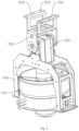
Fig. 1 is a three-dimensional schematic diagram of a tunnel operation robot according to an embodiment of the disclosure; -
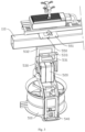
Fig. 2 is a schematic diagram of a rotatable wing module according to an embodiment of the disclosure; -
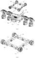
Fig. 3 is a schematic diagram illustrating the connection relationship between the rotatable wing module and the cantilever part according to an embodiment of the disclosure; -
Fig. 4 is a schematic diagram illustrating the connection relationship between the thrust detection device, the rotating fan and the rotating bracket in another embodiment of the disclosure; -
Fig. 5 is an explosive schematic diagram of the tunnel operation robot shown inFig. 1 ; -
Fig. 6 is a schematic diagram of a walking module according to an embodiment of the disclosure. -
Robot body 100;cantilever part 110;detection module 200;walking module 300;second pressure sensor 310;frame body 320;detection port 321;walking assembly 330;driving assembly 340;fixed wing module 400;fixed fan 410;fixing bracket 420;rotatable wing module 500; rotatingfan 510;ear plate 511; connectingpiece 512; winddirection adjustment driver 520; connectingframe 530;first connection part 531;second connection part 532; first connection throughhole 533; rotatingbracket 540; abuttingpart 541; connectingplate 550; second connection throughhole 551;thrust detection device 560. - Embodiments of the present disclosure will be described in detail below. Examples of the embodiments are illustrated in the accompanying drawings, where the same or like reference numerals throughout the figures indicate the same or like elements having the same or like functions. The embodiments described below with reference to the accompanying drawings are exemplary and are intended only to explain the present disclosure instead of being construed as limiting the present disclosure.
- In the description of the present disclosure, it should be understood that, descriptions relating to orientation, for example, orientation or positional relationships indicated by "up", "down", "front", "back", "left", "right", etc. are based on the orientation or positional relationships shown in the accompanying drawings, and are to facilitate the description of the present disclosure and simplify the description only, rather than indicating or implying that the device or element referred to must have a specific orientation or be constructed and operated in a specific orientation, and therefore cannot be construed as limiting the present disclosure.
- In the description of the present disclosure, if "first" and "second", etc. are referred to, it is only for the purpose of distinguishing technical features, and shall not be understood as indicating or implying relative importance or implying the number of the indicated technical features or implying the sequence of the indicated technical features.
- In the description of the present disclosure, unless otherwise explicitly defined, the words such as "set", "install", and "connect" should be understood in a broad sense, and those having ordinary skills in the art can determine the specific meanings of the above words in the present disclosure in a rational way in combination with the specific contents of the technical solutions.
- Referring to accompanying drawings 1 to 6, the tunnel operation robot according to the embodiment of the disclosure will be described below.
- Referring to
Fig. 1 ,Fig. 2 andFig. 5 , a tunnel operation robot according to an embodiment of the disclosure includes arobot body 100, awalking module 300, afixed wing module 400 and a plurality ofrotatable wing modules 500. - Both sides of the
robot body 100 are provided with protrudingcantilever parts 110, and thecantilever parts 110 on both sides are collinearly arranged. Thewalking module 300 is arranged on therobot body 100, and is configured to drive therobot body 100 to walk and turn on a tunnel wall surface. The fixedwing module 400 is arranged on therobot body 100, and includes a fixedfan 410, and is configured to provide pressure for thewalking module 300 to be pressed against the tunnel wall surface. The plurality ofrotatable wing modules 500 are respectively arranged on thecantilever parts 110 on both sides of therobot body 100, and each include a rotatably arranged rotatingfan 510 and a winddirection adjustment driver 520. Each rotatingfan 510 has a rotation axis parallel to an extension direction of thecantilever part 110, and a wind outlet direction perpendicular to the extension direction of thecantilever part 110. The winddirection adjustment driver 520 is connected to the rotatingfan 510 and is configured to keep the wind outlet direction of therotary fan 510 downward to generate a thrust for balancing the gravity. - It can be understood that, in order to realize the tunnel operation, the tunnel operation robot may further be provided with an operation module. In this embodiment, specifically, the operation module is a
detection module 200, and thedetection module 200 is arranged inside therobot body 100. In order to avoid that the casing of therobot body 100 affects the detection operation of thedetection module 200 on the tunnel, a detection end of thedetection module 200 is exposed from therobot body 100, and the detection end is located on a side of therobot body 100 where thewalking module 300 is disposed. - It should be understood that, in addition to being the above-mentioned
detection module 200, the operation module can also be configured according to different types of operations required, and can also include multiple operation modules for completing various types of operations. For example, when a cleaning operation is required, in other embodiments, a vacuum cleaner, an air duct, and a cleaning roller brush similar to the sweeping robot can also be arranged inside therobot body 100, and the surrounding sides of the cleaning roller brush are exposed from therobot body 100, so as to be able to contact the tunnel wall surface to be cleaned. For example, when the image information of the tunnel needs to be collected, a camera device can also be arranged inside therobot body 100, and the camera of the camera device is exposed from therobot body 100, so as to be able to photograph the tunnel wall surface to be photographed. For example, thedetection module 200 and the camera device can also be installed inside therobot body 100 at the same time. - It should be understood that, similarly, the
detection module 200 can also be selected according to the category of items detected on the wall surface of the tunnel, for example, it can be a nuclear magnetic resonance detection device, an electromagnetic wave detection device and an ultrasonic detection device, etc., and the type of thedetection module 200 is not specifically limited herein. - Specifically, when the wall surface of the tunnel is detected by the tunnel operation robot according to the embodiment of the disclosure, firstly, the side of the tunnel operation robot equipped with the
walking module 300 is abutted against the wall surface of the tunnel by manually grabbing the tunnel operation robot (at this time, thecantilever part 110 of the tunnel operation robot is close to a horizontal state, and the extension direction of thecantilever part 110 is roughly close to the extension direction of the tunnel, that is, the length direction of the tunnel). Then the tunnel operation robot is be started to work in the tunnel. After the tunnel operation robot is started, both the fixed-wing module 400 and therotatable wing module 500 start to work. At the same time, the attitude detection mechanism such as gyroscope installed inside therobot body 100 will automatically detect the attitude state of the tunnel operation robot. According to the detected attitude, thewalking module 300 works and performs quick adjustments such as walking and steering, so that thecantilever part 110 is in a horizontal state, that is, the leveling of thecantilever part 110 is completed (since the rotation axis of the rotatingfan 510 is parallel to the extension direction of thecantilever part 110, when thecantilever part 110 is adjusted to a horizontal state, it is convenient to adjust the rotatingfan 510 to enable the air outlet direction to be vertically downward). Almost at the same time, the rotatingfan 510 in therotatable wing module 500 is also driven by the winddirection adjustment driver 520 to complete adjustment of the wind outlet direction to be vertically downward. Therefore, attachment to the wall and suspension can be realized by means of the fixedwing module 400 and therotatable wing module 500. In the detection process, thewalking module 300 drives the entire tunnel operation robot to walk on the wall surface of the tunnel, so that the tunnel operation robot can perform scanning detection on the tunnel wall surface. Moreover, in the detection process, considering that the curvature of the tunnel wall surface changes greatly in the direction of its cross section, but has less change in the length direction of the tunnel, so in order to avoid frequent and large angle adjustment of the rotatingfan 510, in the detection process, the tunnel operation robot may move from one end of the tunnel to the other end of the tunnel along the extension direction of the tunnel, and then the tunnel operation robot may be controlled to move up or down by a position of the tunnel operation robot position along the contour of the tunnel wall on the cross section, and then continue to move from one end to the other end of the tunnel along the extension direction of the tunnel. - It can be seen from the above detection process that the
cantilever part 110 is always kept horizontal in the detection process, and is basically parallel to the extension direction of the tunnel. Moreover, the plurality ofrotatable wing modules 500 arranged to achieve a larger load are installed in a row on thecantilever part 110. Therefore, arrangement of the plurality ofrotatable wing modules 500 only affects the size of the tunnel operation robot in the tunnel extension direction, and does not affect the size of the tunnel operation robot in the direction contained within the cross section of the tunnel, so it is not prone to encountering work blind spots due to interference issues in the direction contained within the cross section of the tunnel. - To sum up, it can be understood that, in the tunnel operation robot according to the embodiment of the disclosure, by means of the fixed
wing module 400, i.e., by means of the thrust generated by the fixedfan 410 in the fixedwing module 400, thewalking module 300 in the tunnel operation robot can be attached to and contact with the tunnel wall surface with a certain pressure. By arranging therotatable wing modules 500, and enabling the rotatingfans 510 in therotatable wing modules 500 to keep the wind outlet direction downward under the drive of the winddirection adjustment driver 520, so that therotatable wing modules 500 can generate a thrust for balancing the gravity, and further by means of thewalking module 300, the walking and steering of the tunnel operation robot on the wall surface can be realized. Therefore, the tunnel operation robot according to the embodiment of the disclosure can use therotatable wing modules 500, the fixedwing module 400 and thewalking module 300 to respectively realize suspension, wall pressing and attaching, and walking, the control process is simpler and easier to operate. Meanwhile, since there are multiplerotatable wing modules 500 for generating an upward thrust, it can generate a more powerful lifting force to balance the gravity, so that the tunnel operation robot can bear greater gravity to carry adetection module 200 with more comprehensive functions and larger weight or other types of operation modules. Moreover, since therotatable wing modules 500 are all connected to thecantilever parts 110 collinearly arranged on both sides of therobot body 100, the plurality of rotatable wing modules arranged to enhance the lifting force are arranged along the same direction, so they only affect the size of the tunnel operation robot in the extension direction of thecantilever part 110, and it is not prone to encountering work blind spots due to interference issues in the direction contained within the cross section of the tunnel. - It can be understood that, in some embodiments, in order to better balance the gravity and prevent the tunnel operation robot from overturning due to the overturning torque generated by the gravity and the lifting force provided by the
rotatable wing modules 500, the rotation axes of the rotatingfans 510 are all located on the same straight line passing through the center of gravity of the tunnel operation robot, so that the tunnel operation robot can be more stable when working. - It can be understood that, in some embodiments, the
rotatable wing modules 500 on thecantilever parts 110 on both sides of therobot body 100 are arranged symmetrically. In case that the rotatingfans 510 have the same specification, the lifting force generated by each rotatingfan 510 when rotating at the same speed is basically the same. By symmetrically arranging therotating wing modules 500 on both sides of therobot body 100, it is easier to keep the tunnel operation robot in balance and avoid overturning when each rotatingfan 510 rotates at the same speed. Therefore, it is convenient to uniformly control the rotating speed of eachrotating fan 510 when the tunnel operation robot works, so as to further improve the control convenience of the tunnel operation robot. - It can be understood that, in an embodiment, the
rotatable wing modules 500 are detachably connected to thecantilever part 110. By detachably connecting therotatable wing modules 500 to thecantilever part 110, it is convenient for the tunnel operation robot to increase or decrease the number of therotatable wing modules 500 according to the weight of thedetection module 200 carried. When the weight is relatively heavy, therotatable wing module 500 may be added on thecantilever part 110, and when the weight is relatively light, therotatable wing module 500 may be removed. - It can be understood that, in an embodiment, in order to facilitate the detachable connection of the
rotatable wing module 500, and also to facilitate the rotatable setting of the rotatingfan 510, referring toFig. 2 andFig. 3 , specifically, therotatable wing module 500 further includes a connectingframe 530 and arotating bracket 540, wherein the rotatingfan 510 is arranged on therotating bracket 540, the winddirection adjustment driver 520 is connected with the connectingframe 530 and therotating bracket 540, and can drive the rotatingbracket 540 to rotate relative to the connectingframe 530, and the connectingframe 530 is detachably connected with thecantilever part 110. - It can be understood that, in order to realize the detachable connection between the connecting
frame 530 and thecantilever part 110, in an embodiment, the connectingframe 530 includes a first connectingpart 531 and a second connectingpart 532 arranged side by side, the first connectingpart 531 and the second connectingpart 532 are each provided with first connecting throughholes 533. Specifically, therotatable wing module 500 further includes a connectingplate 550, and the connectingplate 550 is provided with second connectingholes 551 corresponding to the first connecting throughholes 533. A first threaded connector passes through the first connecting throughhole 533 and is screwed into the second connecting throughhole 551. Thecantilever part 110 passes through a first clamping area formed by the first connectingpart 531, the second connectingpart 532 and the connectingplate 550. Referring toFig. 1 to Fig. 3 , specifically, thecantilever part 110 may extend along the left and right directions, the connectingplate 550 may be located at an upper end of thecantilever part 110, and the connectingplate 550 may be respectively provided with two second connecting throughholes 551 at a front end and a rear end. Correspondingly, the first connectingpart 531 may be provided with two first connecting throughholes 533, the second connectingpart 532 may be provided with two first connecting throughholes 533, and the first connectingpart 531 may be located at a front side of the second connectingpart 532. The first threaded connector may be provided in four. The first threaded connector may be a screw, and correspondingly, the second connecting throughhole 551 is a threaded hole, the first connecting throughhole 533 is a through hole. The first connecting throughholes 533 in the connectingpart 531 may correspond to the second connecting throughholes 551 at the front end of the connectingplate 550. Two screws may be connected to the first connecting throughholes 533 in the first connectingpart 531 and the second connection throughholes 551 at the front end of the connectingplate 550, so that the first connectingpart 531 is connected to the front end of the connectingplate 550. The first connecting throughholes 533 in the second connectingpart 532 may correspond to the second connecting throughholes 551 at the rear end of the connectingplate 550, and the other two screws may be connected to the first connecting throughholes 533 in the second connectingpart 532 and the second connecting throughholes 551 at the rear end of the connectingplate 550, so that the second connectingpart 532 is connected to the rear end of the connectingplate 550. Meanwhile, a first clamping area is formed by the first connectingpart 531, the second connectingpart 532 and the connectingplate 550, and thecantilever part 110 may pass through the first clamping area, so that therotatable wing module 500 is fixed on thecantilever part 110. - It should be understood that, in some other embodiments, the second connection through
hole 551 may also be directly provided on thecantilever part 110, and the screw passing through the first connection throughhole 533 and the second connection throughhole 551 may be directly used to connect the connectingframe 530 to thecantilever part 110. - It can be understood that, in order to facilitate the forming and installation of the
cantilever part 110 on therobot body 100, and also to improve the load-bearing capacity of thecantilever part 110, in an embodiment, the tunnel operation robot further includes a mounting rod, and a middle part of the mounting rod is penetrated through therobot body 100, and both ends of the mounting rod protrude from therobot body 100 to form thecantilever parts 110. Specifically, a shell of therobot body 100 is provided with a perforation that allows the mounting rod to pass through. The middle part of the mounting rod is located inside the shell of therobot body 100, and the mounting rod pass through the above perforation. Moreover, in order to make sure that the lengths of thecantilever parts 110 at left and right sides of therobot body 100 can be the same, left and right ends of the mounting rod exposed from therobot body 100 have the same length. - It should be understood that, in some other embodiments, it is also possible to select two rods and connect the two rods to the left and right sides of the
robot body 100 through a fastener to form twocantilever parts 110 respectively. - It can be understood that, in another embodiment of the disclosure, the tunnel operation robot further includes a control module (not shown in the drawings). Referring to
Fig. 4 , therotatable wing module 500 further includes athrust detection device 560 arranged between therotating bracket 540 and the rotatingfan 510 and configured to detect a thrust transmitted from the rotatingfan 510 to therotating bracket 540. Both thethrust detection device 560 and the rotatingfan 510 are electrically connected to the control module. During operating of the tunnel operation robot, the control module will obtain a theoretical thrust value required to be generated by each rotatingfan 510 according to the gravity or acceleration of the tunnel operation robot, and control the rotating speed of the rotatingfan 510 according to the theoretical thrust value. Thethrust detection device 560 is configured to detect an actual thrust value transmitted to therotating bracket 540 when the rotatingfan 510 is working, so as to adjust the speed of eachrotating fan 510 according to the deviation between the actual thrust value and the theoretical thrust value. For example, when the actual thrust value is smaller than the theoretical thrust value, the actual thrust value is increased by increasing the rotating speed of the rotatingfan 510, and when the actual thrust value is greater than the theoretical thrust value, the actual thrust value is reduced by reducing the rotating speed of the rotatingfan 510, thereby further improving the control accuracy through a closed-loop control. - In an embodiment, specifically, a connecting
piece 512 is provided on an outer side surface of the rotatingfan 510, anabutting part 541 is provided on therotating bracket 540. Theabutting part 541 and the connectingpiece 512 are arranged along a direction parallel to the axis of the rotatingfan 510, and theabutting part 541 is located at a side of the connectingpiece 512 close to an air suction port of the rotatingfan 510. Thethrust detection device 560 is a first pressure sensor, and the first pressure sensor is arranged between the connectingpiece 512 and theabutting part 541, so that when the rotatingfan 510 is working, it can move towards the abuttingpart 541 under its own thrust, to press against the first pressure sensor through the connectingpiece 512, thereby detecting the magnitude of the thrust transmitted from the rotatingfan 510 to therotating bracket 540. - Specifically, the rotating
fan 510 adopts a ducted fan, and the ducted fan includes a ducted cylinder, and fan blades and a motor arranged in the ducted cylinder. Both sides of the ducted cylinder are provided with anear plate 511, and there are two connectingpieces 512 which are respectively connected to the twoear plates 511. Similarly, there are also two abuttingparts 541, which are arranged corresponding to the two connectingpieces 512 respectively. The first pressure sensor is arranged between each of the abuttingparts 541 and a respective one of the connectingpieces 512. - It can be understood that, in an embodiment of the disclosure, referring to
Fig. 5 , similarly, the fixedfan 410 also adopts a ducted fan, and the fixedwing module 400 further includes a fixingbracket 420. The ducted fan in the fixedwing module 400 is fixedly connected to the fixingbracket 420, and the fixingbracket 420 is fixedly connected to therobot body 100. Specifically, there are two fixedwing modules 400, which are respectively arranged on a front side and a rear side of therobot body 100, so as to avoid the installation positions of therotatable wing modules 500. - Referring to
Fig. 5 and Fig. 6 , it can be understood that, according to the invention, a pressure detection device is provided between therobot body 100 and thewalking module 300, and the pressure detection device is configured to detect a pressure transmitted from therobot body 100 to thewalking module 300. Specifically, the pressure detection device includes asecond pressure sensor 310, and thesecond pressure sensor 310 is disposed on thewalking module 300 and abuts against therobot body 100. - It should be understood that, in some other embodiments, the
second pressure sensor 310 may also be disposed on therobot body 100 and abut against thewalking module 300. - In an embodiment, similarly, the control module is also electrically connected to the fixed
fan 410, and can control the pressure exerted by therobot body 100 to thewalking module 300 by controlling the speed of the fixedfan 410. When thesecond pressure sensor 310 detects that the pressure on thewalking module 300 is greater than a set value, a pressure signal is sent to the control module, and the control module controls the fixedfan 410 to reduce the speed, so as to reduce the pressure exerted by therobot body 100 to thewalking module 300. When thesecond pressure sensor 310 detects that the pressure on thewalking module 300 is less than the set value, a pressure signal is sent to the control module, and the control module controls the fixedfan 410 to increase the speed, so as to increase the pressure exerted by therobot body 100 to thewalking module 300. - It can be understood that, in an embodiment, the
walking module 300 includes aframe body 320, a walkingassembly 330 and a drivingassembly 340. The walkingassembly 330 is arranged on theframe body 320 and configure for walking and steering. The drivingassembly 340 is arranged onframe body 320 and connected with the walkingassembly 330 for driving the walkingassembly 330. Theframe body 320 is detachably connected with therobot body 100. Specifically, the pressure detection device is disposed between theframe body 320 and therobot body 100. - It can be understood that, in an embodiment, specifically, the
frame body 320 is detachably connected to therobot body 100 through a threaded fastener. It should be understood that, in some other embodiments, theframe body 320 may also be detachably connected to therobot body 100 in a snap-fit or clamping manner. - It can be understood that, referring to
Fig. 5 and Fig. 6 , in an embodiment, the drivingassembly 340 includes a motor and a coupling, the motor is arranged on theframe body 320, one end of the coupling is connected to an output shaft of the motor, and the other end is connected with the walkingassembly 330. Specifically, in this embodiment, the motors drive thecorresponding walking assemblies 330 through the couplings, and through the differential speed control among the multiple motors, themultiple walking assemblies 330 can realize forward and backward walking and steering actions. - It can be understood that, referring to
Fig. 5 and Fig. 6 , in an embodiment, the walkingassembly 330 is configured as a wheeled-model walking structure, the walkingassembly 330 includes a driving wheel, and the driving wheel is connected to the coupling, and is driven by a motor to rotate. In an embodiment, the driving wheel adopts Mecanum wheel to realize walking and steering, so that the walking and steering of thewalking module 300 are more flexible. In addition, in some other embodiments, the driving wheel may also use rubber wheel to realize walking and steering. - It should be understood that, in some other embodiments, the walking
assembly 330 may also be configured as a crawler-model walking structure. Furthermore, in some other embodiments, the walkingassembly 330 may also adopt a walk-model walking structure. Moreover, in some other embodiments, there are multiple walkingmodules 300, and the walkingmodules 300 adoptdifferent walking assemblies 330, such as respectively adopting a wheeled-model walking structure, a crawler-model walking structure or a walk-model walking structure, so that the tunnel operation robot can adapt to the walking requirements of different environments by selecting and replacing thewalking module 300 with a walkingassembly 330 of a different form. - It should be understood that, in an embodiment, the
walking module 300 is an independent module formed by combination of theframe body 320, the drivingassembly 340 and the walkingassembly 330, and thewalking module 300 and therobot body 100 may be detachably connected, which makes the disassembly and assembly between thewalking module 300 and therobot body 100 more convenient, and when thewalking module 300 fails, thewalking module 300 can be quickly removed from therobot body 100 for replacement or repairment, thereby ensuring the efficiency for operation of the tunnel operation robot. - It can be understood that, referring to
Fig. 5 and Fig. 6 , in an embodiment, theframe body 320 is configured in a framework-mode, and adetection port 321 is formed in the middle thereof, so that when thewalking module 300 is assembled with therobot body 100, thedetection module 200 can be installed in theframe body 320, and the detection end of thedetection module 200 can extend out of theframe body 320. Specifically, after thewalking module 300 is assembled with therobot body 100, theframe body 320 is placed around thedetection module 200 to reduce the space occupied by thewalking module 300 during installation and make the overall structure of the tunnel operation robot more compact. In order to ensure a better detection effect, the distance between the detection end surface of thedetection module 200 and the tunnel wall surface to be detected is controlled between 5mm-15mm, that is, the distance between the point which is farthest from the robot body in the driving wheel and the plane where the detection end surface of thedetection module 200 is located is between 5mm-15mm, and in an embodiment, is specifically 10mm, so as to achieve the best detection effect. - In an embodiment, an elastic pad (not shown in the drawings) is further included, the elastic pad is arranged between the
frame body 320 and therobot body 100, and the elastic pad can be elastically deformed when pressed by an external force, so as to allow theframe body 320 close to therobot body 100. Specifically, the relative movement between theframe body 320 and therobot body 100 is enabled through the arrangement of the elastic pad, so that thesecond pressure sensor 310 can detect the pressure on theframe body 320.
Claims (7)
- A tunnel operation robot, comprising:a robot body (100), provided with protruding cantilever parts (110) on both sides, wherein the cantilever parts (110) on both sides are collinearly arranged;a walking module (300), arranged on the robot body (100) and configured to drive the robot body (100) to walk and steer on a tunnel wall surface;a fixed wing module (400), comprising a fixed fan (410), fixedly arranged on the robot body (100), and configured to provide a pressure for the walking module (300) to be pressed against the tunnel wall surface; anda plurality of rotatable wing modules (500), respectively arranged on the cantilever parts (110) on both sides of the robot body (100), and comprising a rotatable rotating fan (510) and a wind direction adjustment driver (520), wherein each rotating fan (510) has a rotation axis parallel to an extension direction of the cantilever parts (110) and an air outlet direction perpendicular to the extension direction of the cantilever parts (110), and the wind direction adjustment driver (520) is connected to the rotating fan (510), and configured to maintain the air outlet direction of the rotating fan (510) downward to generate a thrust capable of balancing gravity; the rotatable wing modules (500) are detachably connected to the cantilever parts (110),wherein a pressure detection device is provided between the robot body (100) and the walking module (300), and the pressure detection device is configured to detect a pressure transmitted from the robot body (100) to the walking module (300).
- The tunnel operation robot according to claim 1, wherein the rotation axis of each of the rotating fans (510) is located on the same straight line passing through a center of gravity of the tunnel operation robot.
- The tunnel operation robot according to claim 1, wherein the rotatable wing modules (500) on the cantilever parts (110) on both sides of the robot body (100) are arranged symmetrically.
- The tunnel operation robot according to claim 1, wherein each of the rotatable wing modules (500) further comprises a connecting frame (530) and a rotating bracket (540), the rotating fan (510) is arranged on the rotating bracket (540), the wind direction adjustment driver (520) is connected to the connecting frame (530) and the rotating bracket (540), and is capable of driving the rotating bracket (540) to rotate relative to the connecting frame (530), and the connecting frame (530) is detachably connected to a corresponding one of the cantilever parts (110).
- The tunnel operation robot according to claim 4, wherein the tunnel operation robot further comprises a control module, the rotatable wing module (500) further comprises a thrust detection device (560), the thrust detection device (560) is arranged between the rotating bracket (540) and the rotating fan (510), and configured to detect a magnitude of the thrust transmitted from the rotating fan (510) to the rotating bracket (540), and both the thrust detection device (560) and the rotating fan (510) are electrically connected to the control module.
- The tunnel operation robot according to claim 1, wherein the walking module (300) comprises a frame body (320), a walking assembly (330) and a driving assembly (340), the walking assembly (330) is arranged on the frame body (320) and configured for walking and steering, the driving assembly (340) is arranged on the frame body (320) and connected to the walking assembly (330) for driving, the frame body (320) is detachably connected to the robot body (100), and the pressure detection device is arranged between the frame body (320) and the robot body (100).
- The tunnel operation robot according to claim 6, wherein a detection module (200) is arranged inside the robot body (100), the detection module (200) is configured to detect a tunnel, the frame body (320) is arranged in a framework-model manner, a detection port (321) is formed in a middle of the frame body (320), the detection module (200) penetrates through the detection port (321), and a detection end of the detection module (200) protrudes from the frame body (320).
Applications Claiming Priority (1)
| Application Number | Priority Date | Filing Date | Title |
|---|---|---|---|
| CN202211135714.4A CN115214824B (en) | 2022-09-19 | 2022-09-19 | Tunnel operation robot |
Publications (3)
| Publication Number | Publication Date |
|---|---|
| EP4339080A1 EP4339080A1 (en) | 2024-03-20 |
| EP4339080C0 EP4339080C0 (en) | 2024-12-25 |
| EP4339080B1 true EP4339080B1 (en) | 2024-12-25 |
Family
ID=83617656
Family Applications (1)
| Application Number | Title | Priority Date | Filing Date |
|---|---|---|---|
| EP23197978.2A Active EP4339080B1 (en) | 2022-09-19 | 2023-09-18 | Tunnel operation robot |
Country Status (3)
| Country | Link |
|---|---|
| US (1) | US20240092438A1 (en) |
| EP (1) | EP4339080B1 (en) |
| CN (1) | CN115214824B (en) |
Families Citing this family (2)
| Publication number | Priority date | Publication date | Assignee | Title |
|---|---|---|---|---|
| CN119704222B (en) * | 2024-12-30 | 2025-12-02 | 华电科工股份有限公司 | A coal conveyor bridge inspection and drying robot |
| CN119437161B (en) * | 2025-01-13 | 2025-09-30 | 贵阳电气控制设备有限公司 | An automatic settlement monitoring device for tunnel engineering |
Family Cites Families (22)
| Publication number | Priority date | Publication date | Assignee | Title |
|---|---|---|---|---|
| JP5622078B2 (en) * | 2010-03-17 | 2014-11-12 | 独立行政法人産業技術総合研究所 | Wall running robot |
| KR101565979B1 (en) * | 2015-04-13 | 2015-11-13 | 한국항공우주연구원 | Unmanned aerial vehicle |
| KR101767943B1 (en) * | 2015-05-08 | 2017-08-17 | 광주과학기술원 | Multirotor type Unmanned Aerial Vehicle Available for Adjusting Direction of Thrust |
| US10106253B2 (en) * | 2016-08-31 | 2018-10-23 | Bell Helicopter Textron Inc. | Tilting ducted fan aircraft generating a pitch control moment |
| CN107826247A (en) * | 2017-11-15 | 2018-03-23 | 江苏航空职业技术学院 | A kind of rotor unmanned aircraft of two tilting duct of fixed wing of band four |
| CN108731736B (en) * | 2018-06-04 | 2019-06-14 | 山东大学 | Automatic wall-climbing radar optoelectronic robot system for nondestructive detection and diagnosis of bridge and tunnel structural diseases |
| CN109455242B (en) * | 2018-09-30 | 2020-06-05 | 浙江大学 | Modular flexible wall climbing robot |
| WO2020191489A1 (en) * | 2019-03-28 | 2020-10-01 | 10270725 Canada Corp. | Multicopter helicopter and method of manufacture thereof |
| CN111055948A (en) * | 2020-01-02 | 2020-04-24 | 杭州电子科技大学 | Cable tunnel inspection robot based on telescopic gear train |
| CN111176332A (en) * | 2020-03-13 | 2020-05-19 | 山东科技大学 | Tunnel primary support and secondary lining quality detection equipment based on adsorption type unmanned aerial vehicle carrying platform |
| US11794931B2 (en) * | 2020-04-02 | 2023-10-24 | United Parcel Service Of America, Inc. | Modular unmanned aerial vehicle system for adaptable parcel delivery |
| US11630025B2 (en) * | 2020-04-02 | 2023-04-18 | The Florida International University Board Of Trustees | Robotic inspection device |
| CN111645855B (en) * | 2020-05-28 | 2023-03-07 | 西南交通大学 | Diaxon module and use unmanned aerial vehicle of this subassembly |
| WO2022119503A1 (en) * | 2020-12-02 | 2022-06-09 | Nanyang Technological University | Propulsion device for an over-actuated uav |
| CN113126088B (en) * | 2021-03-13 | 2022-06-10 | 中铁十二局集团有限公司 | Tunnel detection robot and tunnel detection method |
| CN112937713B (en) * | 2021-04-02 | 2022-08-23 | 中南大学 | Composite wall-climbing robot and control method thereof |
| CN113220009B (en) * | 2021-07-08 | 2021-09-21 | 中国铁路设计集团有限公司 | Positive pressure type wall climbing robot for tunnel lining detection and control method thereof |
| CN113771979A (en) * | 2021-09-27 | 2021-12-10 | 北京理工大学 | Reverse thrust adsorption wall-climbing robot |
| CN114801615B (en) * | 2022-05-20 | 2024-10-25 | 西安交通大学 | Vector thrust robot |
| CN115489632B (en) * | 2022-09-19 | 2024-09-06 | 中国铁路设计集团有限公司 | Pressure control method for wall-climbing robot |
| CN119319503B (en) * | 2024-12-19 | 2025-04-04 | 泉州市交发工程机械有限公司 | Permanent magnetic wheeled wall climbing robot for tunnel casting template grinding |
| CN120397318B (en) * | 2025-07-04 | 2025-09-16 | 武汉理工大学三亚科教创新园 | A water-air amphibious inspection robot for offshore wind power |
-
2022
- 2022-09-19 CN CN202211135714.4A patent/CN115214824B/en active Active
-
2023
- 2023-09-18 US US18/369,476 patent/US20240092438A1/en active Pending
- 2023-09-18 EP EP23197978.2A patent/EP4339080B1/en active Active
Also Published As
| Publication number | Publication date |
|---|---|
| CN115214824B (en) | 2022-12-13 |
| EP4339080C0 (en) | 2024-12-25 |
| US20240092438A1 (en) | 2024-03-21 |
| CN115214824A (en) | 2022-10-21 |
| EP4339080A1 (en) | 2024-03-20 |
Similar Documents
| Publication | Publication Date | Title |
|---|---|---|
| EP4339080B1 (en) | Tunnel operation robot | |
| CN108583182B (en) | An air-land amphibious spherical robot | |
| WO2021022727A1 (en) | Air-ground amphibious unmanned driving platform | |
| CN211032070U (en) | A land and air inspection robot | |
| US20200324900A1 (en) | Unmanned aerial vehicle and control method for unmanned aerial vehicle | |
| CN113665698B (en) | Wall detection system and detection method based on robotic arm | |
| CN111591438A (en) | A land-air unmanned vehicle | |
| CN112874769A (en) | Aerial work robot | |
| CN110406663A (en) | A kind of unmanned plane of the mapping based on Internet of Things | |
| CN113119670A (en) | Amphibious robot | |
| CN116923013A (en) | Dexterous air-ground amphibious aircraft | |
| CN215851564U (en) | Wall detection system based on robotic arm | |
| CN214492428U (en) | A footed robot with flying ability | |
| CN117885921B (en) | A drone with arms and control method thereof | |
| CN221794921U (en) | Amphibious unmanned aerial vehicle | |
| CN119705659A (en) | Wheel-wing double-drive high-mobility climbing robot | |
| CN102699897A (en) | Full-view probing robot monobody for complex region at ferromagnetic environment | |
| CN103019243B (en) | Based on the self-navigation aircraft of cross flow fan | |
| CN116080945B (en) | Multi-rotor unmanned aerial vehicle capable of switching flight postures and flight method | |
| CN217198637U (en) | A quadrotor UAV with vector thrust function | |
| CN117885829A (en) | Wall climbing unmanned aerial vehicle and control method thereof | |
| CN205440859U (en) | A six rotor craft frames for disaster relief supplies are put in | |
| CN211055271U (en) | An obstacle avoidance robot | |
| CN120704340A (en) | A low-power mobile robot motion control system based on modular design | |
| CN205602105U (en) | A six rotor craft cantilevers for disaster relief supplies are put in |
Legal Events
| Date | Code | Title | Description |
|---|---|---|---|
| PUAI | Public reference made under article 153(3) epc to a published international application that has entered the european phase |
Free format text: ORIGINAL CODE: 0009012 |
|
| STAA | Information on the status of an ep patent application or granted ep patent |
Free format text: STATUS: REQUEST FOR EXAMINATION WAS MADE |
|
| 17P | Request for examination filed |
Effective date: 20230922 |
|
| AK | Designated contracting states |
Kind code of ref document: A1 Designated state(s): AL AT BE BG CH CY CZ DE DK EE ES FI FR GB GR HR HU IE IS IT LI LT LU LV MC ME MK MT NL NO PL PT RO RS SE SI SK SM TR |
|
| GRAP | Despatch of communication of intention to grant a patent |
Free format text: ORIGINAL CODE: EPIDOSNIGR1 |
|
| STAA | Information on the status of an ep patent application or granted ep patent |
Free format text: STATUS: GRANT OF PATENT IS INTENDED |
|
| RIC1 | Information provided on ipc code assigned before grant |
Ipc: B64U 101/00 20230101ALN20240731BHEP Ipc: B64U 101/26 20230101ALI20240731BHEP Ipc: B64U 101/70 20230101ALI20240731BHEP Ipc: B64U 10/10 20230101ALI20240731BHEP Ipc: B64U 10/70 20230101ALI20240731BHEP Ipc: B64U 30/26 20230101ALI20240731BHEP Ipc: B64U 30/29 20230101ALI20240731BHEP Ipc: G01M 3/00 20060101ALI20240731BHEP Ipc: G01N 21/88 20060101ALI20240731BHEP Ipc: E21F 17/00 20060101ALI20240731BHEP Ipc: E21D 11/00 20060101ALI20240731BHEP Ipc: B62D 57/024 20060101AFI20240731BHEP |
|
| INTG | Intention to grant announced |
Effective date: 20240816 |
|
| GRAS | Grant fee paid |
Free format text: ORIGINAL CODE: EPIDOSNIGR3 |
|
| GRAA | (expected) grant |
Free format text: ORIGINAL CODE: 0009210 |
|
| STAA | Information on the status of an ep patent application or granted ep patent |
Free format text: STATUS: THE PATENT HAS BEEN GRANTED |
|
| AK | Designated contracting states |
Kind code of ref document: B1 Designated state(s): AL AT BE BG CH CY CZ DE DK EE ES FI FR GB GR HR HU IE IS IT LI LT LU LV MC ME MK MT NL NO PL PT RO RS SE SI SK SM TR |
|
| REG | Reference to a national code |
Ref country code: GB Ref legal event code: FG4D |
|
| REG | Reference to a national code |
Ref country code: CH Ref legal event code: EP |
|
| REG | Reference to a national code |
Ref country code: DE Ref legal event code: R096 Ref document number: 602023001498 Country of ref document: DE |
|
| REG | Reference to a national code |
Ref country code: IE Ref legal event code: FG4D |
|
| U01 | Request for unitary effect filed |
Effective date: 20250121 |
|
| U07 | Unitary effect registered |
Designated state(s): AT BE BG DE DK EE FI FR IT LT LU LV MT NL PT RO SE SI Effective date: 20250127 |
|
| PG25 | Lapsed in a contracting state [announced via postgrant information from national office to epo] |
Ref country code: NO Free format text: LAPSE BECAUSE OF FAILURE TO SUBMIT A TRANSLATION OF THE DESCRIPTION OR TO PAY THE FEE WITHIN THE PRESCRIBED TIME-LIMIT Effective date: 20250325 |
|
| PG25 | Lapsed in a contracting state [announced via postgrant information from national office to epo] |
Ref country code: GR Free format text: LAPSE BECAUSE OF FAILURE TO SUBMIT A TRANSLATION OF THE DESCRIPTION OR TO PAY THE FEE WITHIN THE PRESCRIBED TIME-LIMIT Effective date: 20250326 |
|
| PG25 | Lapsed in a contracting state [announced via postgrant information from national office to epo] |
Ref country code: RS Free format text: LAPSE BECAUSE OF FAILURE TO SUBMIT A TRANSLATION OF THE DESCRIPTION OR TO PAY THE FEE WITHIN THE PRESCRIBED TIME-LIMIT Effective date: 20250325 |
|
| PG25 | Lapsed in a contracting state [announced via postgrant information from national office to epo] |
Ref country code: SM Free format text: LAPSE BECAUSE OF FAILURE TO SUBMIT A TRANSLATION OF THE DESCRIPTION OR TO PAY THE FEE WITHIN THE PRESCRIBED TIME-LIMIT Effective date: 20241225 |
|
| PG25 | Lapsed in a contracting state [announced via postgrant information from national office to epo] |
Ref country code: PL Free format text: LAPSE BECAUSE OF FAILURE TO SUBMIT A TRANSLATION OF THE DESCRIPTION OR TO PAY THE FEE WITHIN THE PRESCRIBED TIME-LIMIT Effective date: 20241225 |
|
| PG25 | Lapsed in a contracting state [announced via postgrant information from national office to epo] |
Ref country code: ES Free format text: LAPSE BECAUSE OF FAILURE TO SUBMIT A TRANSLATION OF THE DESCRIPTION OR TO PAY THE FEE WITHIN THE PRESCRIBED TIME-LIMIT Effective date: 20241225 |
|
| PG25 | Lapsed in a contracting state [announced via postgrant information from national office to epo] |
Ref country code: IS Free format text: LAPSE BECAUSE OF FAILURE TO SUBMIT A TRANSLATION OF THE DESCRIPTION OR TO PAY THE FEE WITHIN THE PRESCRIBED TIME-LIMIT Effective date: 20250425 |
|
| PG25 | Lapsed in a contracting state [announced via postgrant information from national office to epo] |
Ref country code: SK Free format text: LAPSE BECAUSE OF FAILURE TO SUBMIT A TRANSLATION OF THE DESCRIPTION OR TO PAY THE FEE WITHIN THE PRESCRIBED TIME-LIMIT Effective date: 20241225 |
|
| PG25 | Lapsed in a contracting state [announced via postgrant information from national office to epo] |
Ref country code: CZ Free format text: LAPSE BECAUSE OF FAILURE TO SUBMIT A TRANSLATION OF THE DESCRIPTION OR TO PAY THE FEE WITHIN THE PRESCRIBED TIME-LIMIT Effective date: 20241225 |
|
| U20 | Renewal fee for the european patent with unitary effect paid |
Year of fee payment: 3 Effective date: 20250807 |
|
| PLBE | No opposition filed within time limit |
Free format text: ORIGINAL CODE: 0009261 |
|
| STAA | Information on the status of an ep patent application or granted ep patent |
Free format text: STATUS: NO OPPOSITION FILED WITHIN TIME LIMIT |
|
| 26N | No opposition filed |
Effective date: 20250926 |