EP4339022B1 - Trim part for a motor vehicle - Google Patents
Trim part for a motor vehicle Download PDFInfo
- Publication number
- EP4339022B1 EP4339022B1 EP23196867.8A EP23196867A EP4339022B1 EP 4339022 B1 EP4339022 B1 EP 4339022B1 EP 23196867 A EP23196867 A EP 23196867A EP 4339022 B1 EP4339022 B1 EP 4339022B1
- Authority
- EP
- European Patent Office
- Prior art keywords
- light
- base body
- trim part
- illumination function
- outer side
- Prior art date
- Legal status (The legal status is an assumption and is not a legal conclusion. Google has not performed a legal analysis and makes no representation as to the accuracy of the status listed.)
- Active
Links
Images
Classifications
-
- B—PERFORMING OPERATIONS; TRANSPORTING
- B60—VEHICLES IN GENERAL
- B60Q—ARRANGEMENT OF SIGNALLING OR LIGHTING DEVICES, THE MOUNTING OR SUPPORTING THEREOF OR CIRCUITS THEREFOR, FOR VEHICLES IN GENERAL
- B60Q1/00—Arrangement of optical signalling or lighting devices, the mounting or supporting thereof or circuits therefor
- B60Q1/0029—Spatial arrangement
- B60Q1/0035—Spatial arrangement relative to the vehicle
-
- B—PERFORMING OPERATIONS; TRANSPORTING
- B60—VEHICLES IN GENERAL
- B60Q—ARRANGEMENT OF SIGNALLING OR LIGHTING DEVICES, THE MOUNTING OR SUPPORTING THEREOF OR CIRCUITS THEREFOR, FOR VEHICLES IN GENERAL
- B60Q1/00—Arrangement of optical signalling or lighting devices, the mounting or supporting thereof or circuits therefor
- B60Q1/26—Arrangement of optical signalling or lighting devices, the mounting or supporting thereof or circuits therefor the devices being primarily intended to indicate the vehicle, or parts thereof, or to give signals, to other traffic
- B60Q1/2619—Arrangement of optical signalling or lighting devices, the mounting or supporting thereof or circuits therefor the devices being primarily intended to indicate the vehicle, or parts thereof, or to give signals, to other traffic built in the vehicle body
-
- B—PERFORMING OPERATIONS; TRANSPORTING
- B60—VEHICLES IN GENERAL
- B60Q—ARRANGEMENT OF SIGNALLING OR LIGHTING DEVICES, THE MOUNTING OR SUPPORTING THEREOF OR CIRCUITS THEREFOR, FOR VEHICLES IN GENERAL
- B60Q1/00—Arrangement of optical signalling or lighting devices, the mounting or supporting thereof or circuits therefor
- B60Q1/26—Arrangement of optical signalling or lighting devices, the mounting or supporting thereof or circuits therefor the devices being primarily intended to indicate the vehicle, or parts thereof, or to give signals, to other traffic
- B60Q1/50—Arrangement of optical signalling or lighting devices, the mounting or supporting thereof or circuits therefor the devices being primarily intended to indicate the vehicle, or parts thereof, or to give signals, to other traffic for indicating other intentions or conditions, e.g. request for waiting or overtaking
- B60Q1/503—Arrangement of optical signalling or lighting devices, the mounting or supporting thereof or circuits therefor the devices being primarily intended to indicate the vehicle, or parts thereof, or to give signals, to other traffic for indicating other intentions or conditions, e.g. request for waiting or overtaking using luminous text or symbol displays in or on the vehicle, e.g. static text
-
- B—PERFORMING OPERATIONS; TRANSPORTING
- B60—VEHICLES IN GENERAL
- B60R—VEHICLES, VEHICLE FITTINGS, OR VEHICLE PARTS, NOT OTHERWISE PROVIDED FOR
- B60R13/00—Elements for body-finishing, identifying, or decorating; Arrangements or adaptations for advertising purposes
- B60R13/005—Manufacturers' emblems, name plates, bonnet ornaments, mascots or the like; Mounting means therefor
-
- B—PERFORMING OPERATIONS; TRANSPORTING
- B60—VEHICLES IN GENERAL
- B60R—VEHICLES, VEHICLE FITTINGS, OR VEHICLE PARTS, NOT OTHERWISE PROVIDED FOR
- B60R19/00—Wheel guards; Radiator guards, e.g. grilles; Obstruction removers; Fittings damping bouncing force in collisions
- B60R19/02—Bumpers, i.e. impact receiving or absorbing members for protecting vehicles or fending off blows from other vehicles or objects
- B60R19/48—Bumpers, i.e. impact receiving or absorbing members for protecting vehicles or fending off blows from other vehicles or objects combined with, or convertible into, other devices or objects, e.g. bumpers combined with road brushes, bumpers convertible into beds
- B60R19/50—Bumpers, i.e. impact receiving or absorbing members for protecting vehicles or fending off blows from other vehicles or objects combined with, or convertible into, other devices or objects, e.g. bumpers combined with road brushes, bumpers convertible into beds with lights or registration plates
-
- F—MECHANICAL ENGINEERING; LIGHTING; HEATING; WEAPONS; BLASTING
- F21—LIGHTING
- F21S—NON-PORTABLE LIGHTING DEVICES; SYSTEMS THEREOF; VEHICLE LIGHTING DEVICES SPECIALLY ADAPTED FOR VEHICLE EXTERIORS
- F21S43/00—Signalling devices specially adapted for vehicle exteriors, e.g. brake lamps, direction indicator lights or reversing lights
- F21S43/601—Signalling devices specially adapted for vehicle exteriors, e.g. brake lamps, direction indicator lights or reversing lights characterised by variable optical properties, e.g. involving the use of LCD or movable parts
-
- B—PERFORMING OPERATIONS; TRANSPORTING
- B60—VEHICLES IN GENERAL
- B60R—VEHICLES, VEHICLE FITTINGS, OR VEHICLE PARTS, NOT OTHERWISE PROVIDED FOR
- B60R19/00—Wheel guards; Radiator guards, e.g. grilles; Obstruction removers; Fittings damping bouncing force in collisions
- B60R19/02—Bumpers, i.e. impact receiving or absorbing members for protecting vehicles or fending off blows from other vehicles or objects
- B60R19/48—Bumpers, i.e. impact receiving or absorbing members for protecting vehicles or fending off blows from other vehicles or objects combined with, or convertible into, other devices or objects, e.g. bumpers combined with road brushes, bumpers convertible into beds
- B60R19/50—Bumpers, i.e. impact receiving or absorbing members for protecting vehicles or fending off blows from other vehicles or objects combined with, or convertible into, other devices or objects, e.g. bumpers combined with road brushes, bumpers convertible into beds with lights or registration plates
- B60R2019/505—Bumpers, i.e. impact receiving or absorbing members for protecting vehicles or fending off blows from other vehicles or objects combined with, or convertible into, other devices or objects, e.g. bumpers combined with road brushes, bumpers convertible into beds with lights or registration plates with lights
-
- F—MECHANICAL ENGINEERING; LIGHTING; HEATING; WEAPONS; BLASTING
- F21—LIGHTING
- F21W—INDEXING SCHEME ASSOCIATED WITH SUBCLASSES F21K, F21L, F21S and F21V, RELATING TO USES OR APPLICATIONS OF LIGHTING DEVICES OR SYSTEMS
- F21W2103/00—Exterior vehicle lighting devices for signalling purposes
- F21W2103/20—Direction indicator lights
-
- F—MECHANICAL ENGINEERING; LIGHTING; HEATING; WEAPONS; BLASTING
- F21—LIGHTING
- F21W—INDEXING SCHEME ASSOCIATED WITH SUBCLASSES F21K, F21L, F21S and F21V, RELATING TO USES OR APPLICATIONS OF LIGHTING DEVICES OR SYSTEMS
- F21W2104/00—Exterior vehicle lighting devices for decorative purposes
Definitions
- the invention relates to a trim part for a motor vehicle, wherein the trim part is in particular a front module.
- radiator inlet openings are no longer required to the same extent as for conventional vehicles with combustion engines.
- Front panels in electric vehicles are increasingly getting closed radiator covers, which means better aerodynamics of the vehicle while requiring less cooling air.
- Front panels can be made of transparent polycarbonate and fitted with suitable decorative elements or functional elements, such as lighting modules.
- the front panels are manufactured using a state-of-the-art two-component injection molding process.
- the back i.e. the inside of the three-dimensionally formed front panel
- the front i.e. the outside of the vehicle
- the front must be protected from paint mist.
- the front is masked.
- embossed geometries of the front panel are exposed with a laser.
- the inside is then coated using a physical vapor deposition process (PVD) to create a chrome effect while maintaining light transparency.
- PVD physical vapor deposition process
- a panel part of a motor vehicle which provides a lighting function.
- the panel part has a wall which delimits the interior of the panel part.
- One or more through openings are formed by penetrating the wall.
- a lighting device is arranged in the interior of the panel part and connected to a light source. In order to move the lighting device between an open position in which the light emitted by the lighting device passes through the through openings and a closed position in which the light emitted by the lighting device does not pass through the through openings, an adjustment device is provided.
- the document DE 10 2018 010 030 A1 discloses a rear light of a motor vehicle.
- the rear light consists of a transparent cover glass provided with white light sources.
- the transparent cover glass is colored red for an uncolored transparent window.
- the transparent window is equipped with a mechanically movable filter element.
- a red-colored area is located between the window and the light sources.
- the uncolored transparent area is located between the window and the light sources and is arranged on optical lenses.
- the document FR 3117574 A1 discloses a fairing part with a movable section. In a retracted position, this section serves as a reflector.
- a cladding part with the following features: with a base body which has a visible side facing the outside and an inner side and which, at least in one partial area, comprises a light window in the form of a light-permeable transparent or translucent area, and at least in one partial area a non-light-permeable area with a color-providing coating, with a lighting function which is arranged behind the visible side of the base body for transilluminating or illuminating the light window and with a device which has a visible side which has a color-providing coating, wherein the device is adjustably connected to the base body such that the device closes the light window in a first position and completely covers the lighting function when viewed from the outside and the visible side is oriented towards the outside and, in a second position, releases the light window and the lighting function when viewed from the outside such that the lighting function is visible through the light window when viewed from the outside.
- the covering part according to the invention makes it possible to implement a lighting function/functional lighting with a "disappearing function" (secret until lit).
- a lighting function/functional lighting with a "disappearing function" (secret until lit).
- the lighting function which comprises at least one light source, is visible to a user from the outside and the device is adjusted to a corresponding second position.
- the device with the covering part can also have more than two adjustable positions and thus represent different lighting functions that vary in brightness, beam angle, illumination angle and illumination position, etc.
- the panel part according to the invention also makes it possible to provide the user of a motor vehicle and/or a road user with different lighting functions, at least temporarily.
- These lighting functions can include both safety-related aspects and communication options through illuminated symbols and lettering.
- the lighting functions can also include design features. This expands the functional options for illuminated front panels. Another function that can be integrated could be the indicator function.
- the device is connected to a base body of the cladding element and can be adjusted to the first and second positions. Other positions are also possible.
- the device advantageously fits flush into a light window formed in the base body in such a way that the cladding element has a uniform appearance.
- this uniform appearance is a paint finish in a uniform color. Accordingly, the visible side of the device facing the outside is also provided with a paint finish and/or coating in the first position.
- the visible side can also have numbers, lettering, emblems, reflectors and/or design elements and thus not completely merge with the outer contour of the vehicle.
- the device in the first position is inserted into the base body or the decorative carrier in the area of the light window in such a way that on the A flush, seamless surface area is formed on the outside of the cladding part.
- the color-giving coating on the visible side of the device is the same color as the color-giving coating on the base body, whereby this color corresponds to the color of the motor vehicle.
- the device In the second position, the device is attached to the base body of the cladding element in such a way that the lighting function is visible to a user from the outside of the motor vehicle through the light window formed in the base body.
- the adjustment movement is advantageously achieved via suitable kinematic elements.
- the base body of the cladding element is advantageously a composite component which comprises a deep-drawn decorative carrier, in particular a film, back-injected with a transparent polymer material, wherein the decorative carrier is at least partially provided with a layer of color and has at least one transparent or translucent light window.
- the outside is the surface that is visible to a user from the environment.
- the inside is the side opposite the outside that faces the inside.
- a cladding part is considered to be, in particular, an external cladding part such as a front panel, wherein the front panel is designed three-dimensionally.
- the light window in the sense of the present invention can be a transparent or partially transparent/translucent area formed in the base body of the cladding element.
- the base body is made, for example, from a deep-drawn film into which a corresponding cutout is made, the film then being back-molded with a transparent plastic material in an injection molding process.
- the side back-molded with transparent plastic material preferably a polycarbonate, forms the visible side of the motor vehicle for a user in the finished and assembled situation of the cladding element.
- the color-giving coating can be produced by varnishing or a varnish film.
- the lighting function is produced by at least one light source.
- One or more LEDs can serve as the light source.
- the light from the light source can be coupled into a light guide body, which emits the light at corresponding light output structures.
- the device is a section that can be adjusted outwardly in a translational manner.
- the trim part 40 according to the invention is described below using a front panel as an external trim in the front area of an electric vehicle. It goes without saying that such a trim part 40 can also be used as a trim element at any other location in a motor vehicle.
- the trim part 40 is preferably also a bumper trim, a tailgate trim, a door trim, a roof trim or a spoiler or is a component of one of the aforementioned parts.
- the trim part 40 has a base body 2, which is a three-dimensionally formed plastic composite component that can be manufactured using various manufacturing processes or process steps.
- the trim part 40 is shown in the drawing as a section in a schematic sectional view and has a front side (V) and a back side (R).
- the front side V is the visible side of the outer skin of the motor vehicle in the intended installation situation on the motor vehicle and is visible to a user.
- the plastic composite component comprises a deep-drawn, three-dimensionally formed decorative carrier 4 and at least one transparent cover layer 5 arranged on the outside.
- the decorative carrier 4 is a plastic film, in particular a transparent plastic film, which has a colored coating/paint on the side facing the outside.
- the paint can correspond to the paint of the motor vehicle in terms of color design.
- the film as decorative carrier 4 is back-injected in an injection molding process with a transparent polymer material for producing the cover layer 5, preferably a polycarbonate, at least on the side facing the front.
- the Figure 1 shows in one embodiment the covering part 40 according to the invention with a base body 2 provided with a color-imparting coating.
- the base body 2 is made of a plastic material such as PP, polycarbonate or ABS and is painted in color.
- the base body has a large number of openings or recesses that form the light windows 49.
- the light windows 49 are conical with an inwardly extending bevel.
- the device 47 is designed in the form of sliding elements, also referred to below as inserts.
- the sliding elements are mounted in the light windows 49 so that they can be moved longitudinally and have a head section 47a with a visible side S5 facing the outside and a contact section 46 formed on the back.
- this contact section 46 is designed to be conical or circumferentially chamfered in a manner corresponding to the chamfered or conical openings in the base body 2 and thus enables the head section 47a to be received flush in the light windows in the first position.
- the inserts are designed with a pin that is guided through the opening.
- the large number of inserts are connected to a holding element on the back via this pin, which can be adjusted to the second position, which is in the Figure 1 is shown, comprises kinematics and actuators assigned to the holding element.
- the inserts can be designed as decorative elements at least in the head section 47a and can be designed with different colors, or as a chrome-plated or PVD-coated component at least on the visible side facing the outside, side S5.
- the sliding elements or inserts are painted at least on the visible side S5 in the same way as the painted base body 2 or the decorative carrier 4. This color corresponds to the color of the vehicle, so that in the first position in which the device is inserted flush into the base body, a uniform, as seamless as possible appearance is created for a user starting from the outside.
- the device 47 or the plurality of sliding elements are pushed outwards over the surface contour of the base body 2 via the holding element by means of an adjustment movement.
- a circumferential light gap 49a is created between the openings in the base body 2 and the sliding elements, so that the lighting function 48 is released and the emitted light can radiate through the light gap to the outside.
- the lighting function 48 that can be released in the second state is formed by the base body 2, which is designed as a light guide body 53 at least in a rear partial area.
- a light source 52 arranged in the interior at the rear couples the light into the light guide body.
- the light guide body also includes the chamfered section in the base body that forms the circumferential contour of the light window. The light is then emitted through the circumferential contour as a light exit surface 49 through the light gap 49a to the outside.
- the transparent light-emitting surface in the base body is created by masking or by removing (mechanically, lasering, etc.) the color-giving coating.
- the light element itself is designed in such a way that it is embedded in the base body in the area of the opening and thus represents the circumferential contour of the opening.
- the characteristic of the bevelled, conical surfaces in the base body that delimit the light windows and the corresponding contact surfaces on the sliding element is that, during the adjustment movement in the first position, they form a defined closing point for pulling the sliding elements back into the closed state in order to create the smoothest possible image without joints on the outer surface of the cladding part. Furthermore, the lighting function itself is concealed in this first position and is not visible when closed.
- the shape of the openings and the sliding elements is defined in claim 1. However, it can be chosen in such a way that, in addition to square and round shapes, more complex contours such as brand emblems and lettering can also be represented.
Landscapes
- Engineering & Computer Science (AREA)
- Mechanical Engineering (AREA)
- General Engineering & Computer Science (AREA)
- Lighting Device Outwards From Vehicle And Optical Signal (AREA)
- Arrangements Of Lighting Devices For Vehicle Interiors, Mounting And Supporting Thereof, Circuits Therefore (AREA)
- Vehicle Waterproofing, Decoration, And Sanitation Devices (AREA)
- Vehicle Interior And Exterior Ornaments, Soundproofing, And Insulation (AREA)
Description
Die Erfindung betrifft ein Verkleidungsteil für ein Kraftfahrzeug, wobei das Verkleidungsteil insbesondere ein Frontmodul ist.The invention relates to a trim part for a motor vehicle, wherein the trim part is in particular a front module.
Durch die zunehmende Verbreitung von elektrischen Fahrzeugen ändern sich die Anforderungen an Frontpanele, da keine Kühlereintrittsöffnungen in demselben Maß wie für konventionelle Kraftfahrzeuge mit Verbrennungsmotoren gefordert sind.Due to the increasing popularity of electric vehicles, the requirements for front panels are changing, as radiator inlet openings are no longer required to the same extent as for conventional vehicles with combustion engines.
Frontpanele in elektrischen Fahrzeugen bekommen mehr und mehr geschlossene Kühlerverkleidungen, was eine bessere Aerodynamik des Fahrzeugs bei gleichzeitig weniger Kühlluftbedarf entspricht.Front panels in electric vehicles are increasingly getting closed radiator covers, which means better aerodynamics of the vehicle while requiring less cooling air.
Frontpanele können aus transparentem Polycarbonat gefertigt und mit geeigneten Dekorationselementen oder auch Funktionselementen, wie beispielsweise Beleuchtungsmodulen versehen werden. Hierfür werden die Frontpanele gemäß dem Stand der Technik in einem Zweikomponenten Spritzgussverfahren hergestellt.Front panels can be made of transparent polycarbonate and fitted with suitable decorative elements or functional elements, such as lighting modules. For this purpose, the front panels are manufactured using a state-of-the-art two-component injection molding process.
Die Rückseite, also die Fahrzeuginnenseite des dreidimensional geformten Frontpanels, wird anschließend lackiert, wobei die Vorderseite, also die Außenseite des Fahrzeugs, vor Lacknebel geschützt werden muss. Dazu wird die Vorderseite maskiert. Zur Herstellung von mehrfarbigen Strukturen werden eingeprägte Geometrien des Frontpanel mit einem Laser freigelegt. Anschließend erfolgt eine Beschichtung der Innenseite mit einem physikalischen Gasabscheideverfahren (PVD), um einen Chrom effekt bei gleichzeitiger Lichttransparenz zu bekommen. Die Vorderseite erhält eine Hartlackbeschichtung.The back, i.e. the inside of the three-dimensionally formed front panel, is then painted, while the front, i.e. the outside of the vehicle, must be protected from paint mist. To do this, the front is masked. To produce multi-colored structures, embossed geometries of the front panel are exposed with a laser. The inside is then coated using a physical vapor deposition process (PVD) to create a chrome effect while maintaining light transparency. The front is given a hard lacquer coating.
Des Weiteren ist es bekannt in die Frontpanele separate Bauteile wie beispielsweise Markensymbole zu integrieren. Die Bauteile können mit Chromfolie dekoriert und anschließend in entsprechende Ausnehmungen des in der Farbgestaltung des Lacks des Kraftfahrzeugs lackierten Kunststoffformteile eingesetzt werden.It is also known to integrate separate components such as brand symbols into the front panels. The components can be covered with chrome foil decorated and then inserted into corresponding recesses in the plastic molded parts painted in the color of the vehicle's paintwork.
Diese dekorierten Bauteile wie beispielsweise Markensymbole können durch den Einsatz von lichtdurchlässigen Werkstoffen von der Rückseite beleuchtet werden und bilden damit eine dekorative Beleuchtungsfunktion. Derartig bekannte Verkleidungselemente mit integrierten Leuchtfunktionen haben allerdings den Nachteil, dass die Beleuchtung nur dekorativ ist und keine Funktionsbeleuchtung.These decorated components, such as brand symbols, can be illuminated from the back by using translucent materials, thus providing a decorative lighting function. However, such well-known cladding elements with integrated lighting functions have the disadvantage that the lighting is only decorative and not functional lighting.
Aus dem Dokument
Das Dokument
Das Dokument
Es ist Aufgabe der Erfindung, ein Verkleidungsteil mit einer farbig gestalteten Sichtseite, wobei die Farbe vorzugsweise die Wagenfarbe ist, für ein Kraftfahrzeug bereitzustellen, welches zumindest eine Beleuchtungsfunktion bereitstellt, wobei ein Lichtmodul mit einer Lichtfunktion in einem ersten Zustand für einen Nutzer von der Außenseite des Kraftfahrzeugs gesehen nicht sichtbar und in einem zweiten Zustand für einen Nutzer von der Außenseite gesehen sichtbar ist.It is an object of the invention to provide a trim part with a colored visible side, wherein the color is preferably the vehicle color, for a motor vehicle, which provides at least one lighting function, wherein a light module with a lighting function is not visible to a user in a first state when viewed from the outside of the motor vehicle and is visible to a user in a second state when viewed from the outside.
Die Aufgabe wird durch ein Verkleidungsteil mit folgenden Merkmalen gelöst: mit einem Grundkörper, der eine zur Außenseite weisende Sichtseite und eine Innenseite aufweist und der zumindest in einem Teilbereich ein Lichtfenster in Form eines lichtdurchscheinenden transparenten oder transluzenten Bereichs, und zumindest in einem Teilbereich einen nicht lichtdurchlässigen Bereich mit einer farbgebenden Beschichtung umfasst, mit einer Beleuchtungsfunktion, die hinter der Sichtseite des Grundkörpers zur Durchleuchtung oder Beleuchtung des Lichtfensters angeordnet ist und mit einer Vorrichtung, die eine Sichtseite aufweist, die eine farbgebende Beschichtung aufweist, wobei die Vorrichtung derart verstellbar an dem Grundkörper angebunden ist, dass die Vorrichtung in einer ersten Position das Lichtfenster verschließt und die Beleuchtungsfunktion von der Außenseite gesehen vollständig abdeckt und die Sichtseite zur Außenseite hin weisend ausgerichtet ist und in einer zweiten Position das Lichtfenster und die Beleuchtungsfunktion von der Außenseite gesehen derart freigibt, dass die Beleuchtungsfunktion durch das Lichtfenster von der Außenseite gesehen sichtbar ist.The object is achieved by a cladding part with the following features: with a base body which has a visible side facing the outside and an inner side and which, at least in one partial area, comprises a light window in the form of a light-permeable transparent or translucent area, and at least in one partial area a non-light-permeable area with a color-providing coating, with a lighting function which is arranged behind the visible side of the base body for transilluminating or illuminating the light window and with a device which has a visible side which has a color-providing coating, wherein the device is adjustably connected to the base body such that the device closes the light window in a first position and completely covers the lighting function when viewed from the outside and the visible side is oriented towards the outside and, in a second position, releases the light window and the lighting function when viewed from the outside such that the lighting function is visible through the light window when viewed from the outside.
Durch das erfindungsgemäße Verkleidungsteil ist es möglich eine Beleuchtungsfunktion / Funktionsbeleuchtung mit einer "Verschwindefunktion" (secret until lit) zu realisieren. Dies bedeutet, dass in einem ersten Zustand für einen Nutzer die Beleuchtungsfunktion nicht sichtbar ist und durch eine erste Position einer Vorrichtung abgedeckt ist. In einem zweiten Zustand ist die Beleuchtungsfunktion, die zumindest eine Lichtquelle umfasst, für eine Nutzer von der Außenseite her sichtbar und die Vorrichtung ist in einer entsprechenden zweiten Position verstellt. Allgemein kann die Vorrichtung mit dem Verkleidungsteil auch mehr als zwei einstellbare Positionen aufweisen und so verschiedene Beleuchtungsfunktionen, die in Helligkeit, Abstrahlwinkel, Anleuchtewinkel und Anstrahlposition usw. variieren, darstellen.The covering part according to the invention makes it possible to implement a lighting function/functional lighting with a "disappearing function" (secret until lit). This means that in a first state the lighting function is not visible to a user and is covered by a first position of a device. In a second state the lighting function, which comprises at least one light source, is visible to a user from the outside and the device is adjusted to a corresponding second position. In general, the device with the covering part can also have more than two adjustable positions and thus represent different lighting functions that vary in brightness, beam angle, illumination angle and illumination position, etc.
Durch das erfindungsgemäße Verkleidungsteil ist es weiterhin möglich dem Nutzer eines Kraftfahrzeugs und/oder einem Verkehrsteilnehmer unterschiedliche Leuchtfunktionen zumindest zeitweise zur Verfügung zu stellen. Diese Leuchtfunktionen können sowohl sicherheitsrelevante Aspekte als auch Kommunikationsmöglichkeiten durch beleuchtete Symbole, Schriftzüge beinhalten. Die Leuchtfunktionen können auch Designmerkmale beinhalten. Hierdurch wird eine Erweiterung der Funktionsmöglichkeiten bei beleuchteten Frontpanels erreicht. Als weitere integrierbare Funktion ist beispielsweise die Blinkerfunktion vorstellbar.The panel part according to the invention also makes it possible to provide the user of a motor vehicle and/or a road user with different lighting functions, at least temporarily. These lighting functions can include both safety-related aspects and communication options through illuminated symbols and lettering. The lighting functions can also include design features. This expands the functional options for illuminated front panels. Another function that can be integrated could be the indicator function.
Die Vorrichtung ist dabei in die erste und zweite Position verstellbar an einem Grundkörper des Verkleidungselements angebunden. Weitere Positionen sind ebenfalls möglich.The device is connected to a base body of the cladding element and can be adjusted to the first and second positions. Other positions are also possible.
In dem ersten Zustand und der ersten Position der Vorrichtung fügt sich die Vorrichtung in ein in dem Grundkörper gebildetes Lichtfensters in den Grundkörper vorteilhafterweise bündig ein derart, dass das Verkleidungselement ein einheitliches Erscheinungsbild hat. Dieses einheitliche Erscheinungsbild ist in einer Ausführungsform eine Lackierung in einer einheitlichen Farbe. Dementsprechend ist die zur Außenseite hin gerichtete Sichtseite der Vorrichtung in der ersten Position ebenfalls mit einer Lackierung und/oder Beschichtung versehen.In the first state and the first position of the device, the device advantageously fits flush into a light window formed in the base body in such a way that the cladding element has a uniform appearance. In one embodiment, this uniform appearance is a paint finish in a uniform color. Accordingly, the visible side of the device facing the outside is also provided with a paint finish and/or coating in the first position.
In weiteren Ausführungsformen kann die Sichtseite auch Zahlen, Schriftzüge, Embleme, Reflektoren und/oder Designelemente aufweisen und somit nicht völlig mit der Außenkontur des Fahrzeugs verschmelzen.In further embodiments, the visible side can also have numbers, lettering, emblems, reflectors and/or design elements and thus not completely merge with the outer contour of the vehicle.
Vorteilhafterweise fügt sich die Vorrichtung in der ersten Position derart in dem Grundkörper bzw. dem Dekorträger im Bereich des Lichtfensters ein, dass auf der Außenseite des Verkleidungsteils ein flächenbündiger, fugenloser Oberflächenbereich ausgebildet ist.Advantageously, the device in the first position is inserted into the base body or the decorative carrier in the area of the light window in such a way that on the A flush, seamless surface area is formed on the outside of the cladding part.
Die farbgebende Beschichtung der Sichtseite der Vorrichtung ist dabei in einer besonders bevorzugten Ausführungsform die gleiche Farbe wie die farbgebende Beschichtung des Grundkörpers, wobei diese Farbe der Wagenfarbe des Kraftfahrzeugs entspricht. Hierdurch ist in der ersten Position der Vorrichtung von der Außenseite des Kraftfahrzeugs für den Nutzer eine einheitliche farbgebende Beschichtung über das Verkleidungsteil wahrnehmbar.In a particularly preferred embodiment, the color-giving coating on the visible side of the device is the same color as the color-giving coating on the base body, whereby this color corresponds to the color of the motor vehicle. As a result, in the first position of the device, the user can see a uniform color-giving coating over the trim part from the outside of the motor vehicle.
In der zweiten Position ist die Vorrichtung derart verstellt an dem Grundkörper des Verkleidungselements angebunden gehalten, dass die Beleuchtungsfunktion, durch das in dem Grundkörper gebildete Lichtfenster von der Außenseite des Kraftfahrzeugs für einen Nutzer sichtbar ist.In the second position, the device is attached to the base body of the cladding element in such a way that the lighting function is visible to a user from the outside of the motor vehicle through the light window formed in the base body.
Die Verstellbewegung wird vorteilhafterweise über geeignete Kinematikelemente erreicht.The adjustment movement is advantageously achieved via suitable kinematic elements.
Der Grundkörper des Verkleidungselements ist vorteilhafterweise ein Verbundbauteil, welches eine mit einem transparenten Polymermaterial hinterspritzte tiefgezogene Dekorträger, insbesondere Folie umfasst, wobei der Dekorträger zumindest teilweise mit einer Farbschicht versehen ist und zumindest ein transparentes oder transluzentes Lichtfenster aufweist.The base body of the cladding element is advantageously a composite component which comprises a deep-drawn decorative carrier, in particular a film, back-injected with a transparent polymer material, wherein the decorative carrier is at least partially provided with a layer of color and has at least one transparent or translucent light window.
Nachfolgend Definitionen im Sinne der vorliegenden Erfindung. Als Außenseite wird die von der Umgebung her für einen Nutzer sichtbare Oberfläche gesehen. Die Innenseite ist dementsprechend die der Außenseite gegenüberliegende zur Innenseite weisende Seite.The following definitions are used in the context of the present invention. The outside is the surface that is visible to a user from the environment. The inside is the side opposite the outside that faces the inside.
Als Verkleidungsteil wird insbesondere ein Außenverkleidungsteil wie beispielsweise ein Frontpanel angesehen, wobei das Frontpanel dreidimensional ausgestaltet ist.A cladding part is considered to be, in particular, an external cladding part such as a front panel, wherein the front panel is designed three-dimensionally.
Das Lichtfenster im Sinne der vorliegenden Erfindung kann ein im Grundkörper des Verkleidungselements ausgebildeter transparenter oder teiltransparenter/transluzenter Bereich sein. Der Grundkörper ist beispielsweise durch eine tiefgezogene Folie, in die eine entsprechende Ausstanzung eingebracht ist, wobei die Folie anschließend in einem Spritzgießverfahren mit einem transparenten Kunststoffmaterial hinterspritzt ausgebildet ist, hergestellt. Die mit transparenten Kunststoffmaterial, vorzugsweise einem Polycarbonat, hinterspritzte Seite bildet in der fertiggestellten und montierten Situation des Verkleidungselements die Sichtseite am Kraftfahrzeug für einen Nutzer.The light window in the sense of the present invention can be a transparent or partially transparent/translucent area formed in the base body of the cladding element. The base body is made, for example, from a deep-drawn film into which a corresponding cutout is made, the film then being back-molded with a transparent plastic material in an injection molding process. The side back-molded with transparent plastic material, preferably a polycarbonate, forms the visible side of the motor vehicle for a user in the finished and assembled situation of the cladding element.
Die farbgebende Beschichtung kann durch eine Lackierung oder eine Lackfolie hergestellt sein.The color-giving coating can be produced by varnishing or a varnish film.
Die Beleuchtungsfunktion wird durch zumindest eine Lichtquelle hergestellt. Als Lichtquelle kann eine oder können mehrere LEDs dienen. Das Licht der Lichtquelle kann in einer bevorzugten Ausführungsform in einen Lichtleitkörper eingekoppelt werden, der das Licht an entsprechenden Lichtauskoppelstrukturen abstrahlt.The lighting function is produced by at least one light source. One or more LEDs can serve as the light source. In a preferred embodiment, the light from the light source can be coupled into a light guide body, which emits the light at corresponding light output structures.
Erfindungsgemäß ist die Vorrichtung ein translatorisch nach außen verstellbarer Abschnitt.According to the invention, the device is a section that can be adjusted outwardly in a translational manner.
Die Erfindung wird nachfolgend beispielhaft unter Bezugnahme auf die beigefügte Zeichnung beschrieben.
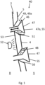
- Fig. 1
- eine Ausführungsform in einem Schnittbild in dem zweiten Zustand, in dem die Lichtfunktion freigegeben und aktiviert ist.
- Fig. 1
- an embodiment in a sectional image in the second state in which the light function is released and activated.
Das erfindungsgemäße Verkleidungsteil 40 wird nachfolgend anhand eines Frontpanels als Außenverkleidung im Frontbereich eines Elektrofahrzeugs beschrieben. Es ist selbstverständlich, dass ein derartiges Verkleidungsteil 40 auch an beliebiger anderer Stelle eines Kraftfahrzeugs als Verkleidungselement eingesetzt werden kann. Das Verkleidungsteil 40 ist bevorzugt auch eine Stoßfängerverkleidung, eine Heckklappenverkleidung, eine Türverkleidung, eine Dachverkleidung oder ein Spoiler oder ist ein Bauteil eines der vorgenannten Teile.The
Das Verkleidungsteil 40 weist einen Grundkörper 2 auf, der ein dreidimensional ausgeformtes Kunststoffverbundbauteil ist, welches in verschiedenen Herstellverfahren bzw. Verfahrensschritten gefertigt werden kann. Das Verkleidungsteil 40 ist in der Zeichnung als Ausschnitt in einer schematischen Schnittdarstellung gezeigt und weist eine Vorderseite (V) und eine Rückseite (R) auf. Die Vorderseite V ist die Sichtseite der Außenhaut des Kraftfahrzeugs in der bestimmungsgemäßen Einbausituation am Kraftfahrzeug und für einen Nutzer sichtbar.The
Das Kunststoffverbundbauteil umfasst einen tiefgezogenen dreidimensional ausgebildeten Dekorträger 4 und zumindest eine außenseitig angeordnete transparente Abdeckschicht 5. Der Dekorträger 4 ist eine Kunststofffolie, insbesondere eine transparente Kunststofffolie, die eine farbige Beschichtung/Lackierung, auf der der Außenseite zugewandten Seite aufweist. Die Lackierung kann hinsichtlich der Farbgestaltung der Lackierung des Kraftfahrzeugs entsprechen.The plastic composite component comprises a deep-drawn, three-dimensionally formed
Die Folie als Dekorträger 4 ist in einem Spritzgießverfahren mit einem transparenten Polymermaterial zur Herstellung der Abdeckschicht 5, vorzugsweise einem Polycarbonat zumindest auf der zur Vorderseite weisenden Seite hinterspritzt.The film as
Die
Wie es aus der Zeichnung zu erkennen ist, ist die Vorrichtung 47 in Form von Schiebeelementen nachfolgend auch Inserts genannt ausgeführt. Die Schiebeelemente sind in den Lichtfenstern 49 längsverschieblich gelagert angeordnet und weisen einen Kopfabschnitt 47a mit einer zur Außenseite hin gerichteten Sichtseite S5 und einen rückseitig daran angeformten Anlageabschnitt 46 auf. Dieser Anlageabschnitt 46 ist hinsichtlich seiner Geometrie korrespondierend zu den gefasten bzw. konisch ausgebildeten Durchbrüchen des Grundkörpers 2 konischen bzw. umlaufend gefast ausgeführt und ermöglicht somit eine flächenbündige Aufnahme des Kopfabschnitts 47a in den Lichtfenstern in der ersten Position.As can be seen from the drawing, the
Im Anschluss an den Anlageabschnitt 46 sind die Inserts mit einem durch den Durchbruch geführten Pin ausgeführt. Über diesen Pin sind die Vielzahl der Inserts rückseitig an einem Halteelement angebunden, welches zur Verstellung in die zweite Position, die in der
Die Inserts können zumindest im Kopfabschnitt 47a als Dekorationselemente ausgeführt und mit unterschiedlichen Farben, oder als verchromtes oder PVD beschichtetes Bauteil zumindest auf der zur Außenseite hin gerichteten Sichtseite Seite S5 ausgeführt werden.The inserts can be designed as decorative elements at least in the
In einer Ausführungsform sind die Schiebeelemente bzw. Inserts zumindest auf der Sichtseite S5 gleichermaßen, wie der lackierte Grundkörper 2 bzw. der Dekorträger 4 lackiert. Diese Farbe entspricht der Wagenfarbe, so dass sich hierdurch in der ersten Position, in der die Vorrichtung flächenbündig in dem Grundkörper eingefügt ist, ein einheitliches möglichst fugenloses Erscheinungsbild ausgehend von der Außenseite für einen Nutzer gebildet ist.In one embodiment, the sliding elements or inserts are painted at least on the visible side S5 in the same way as the painted
Bei der in der
Die in dem zweiten Zustand freigebbare Beleuchtungsfunktion 48 wird dabei durch den Grundkörper 2 gebildet, der zumindest in einem rückseitigen Teilbereich als Lichtleitkörper 53 ausgeführt ist. Eine rückseitig im Innenraum angeordnete Lichtquelle 52 koppelt dabei das Licht in den Lichtleitkörper ein. Der Lichtleitkörper umfasst dabei auch den gefasten Abschnitt im Grundkörper, der die umlaufende Kontur des Lichtfensters bildet. Das Licht wird dann durch die umlaufende Kontur als Lichtaustrittsfläche 49 durch den Lichtspalt 49a zur Außenseite hin abgestrahlt.The
Die transparente Lichtaustrittsfläche im Grundkörper wird durch Maskierung, oder durch Abtrag (mechanisch, Lasern, usw.) der farbgebenden Beschichtung hergestellt.The transparent light-emitting surface in the base body is created by masking or by removing (mechanically, lasering, etc.) the color-giving coating.
In einer nicht dargestellten Ausführungsform ist das Lichtelement selbst so gestaltet, dass es in dem Grundkörper im Bereich des Durchbruchs eingebettet gehalten ist und so die umlaufende Kontur des Durchbruchs darstellt.In an embodiment not shown, the light element itself is designed in such a way that it is embedded in the base body in the area of the opening and thus represents the circumferential contour of the opening.
Merkmal der gefasten, konisch verlaufenden die Lichtfenster begrenzenden Flächen im Grundkörper und der korrespondierend ausgeführten Anlageflächen am Schiebeelement ist, dass diese bei der Verstellbewegung in der ersten Position zueinander einen definierten Schließpunkt für Zurückziehen der Schiebeelemente in den geschlossenen Zustand bilden, um auf der Außenfläche des Verkleidungsteils ein möglichst ebenes fugenfreies Bild zu erzeugen. Des Weiteren ist in dieser ersten Position die Beleuchtungsfunktion selbst verdeckt und im geschlossenen Zustand nicht sichtbar.The characteristic of the bevelled, conical surfaces in the base body that delimit the light windows and the corresponding contact surfaces on the sliding element is that, during the adjustment movement in the first position, they form a defined closing point for pulling the sliding elements back into the closed state in order to create the smoothest possible image without joints on the outer surface of the cladding part. Furthermore, the lighting function itself is concealed in this first position and is not visible when closed.
Die Form der Durchbrüche und der Schiebeelemente ist in Anspruch 1 definiert. Sie kann jedoch so gewählt werden, dass hier neben eckigen, wie runden Formen auch komplexere Konturen wie Markenembleme und Schriftzüge dargestellt werden können.The shape of the openings and the sliding elements is defined in claim 1. However, it can be chosen in such a way that, in addition to square and round shapes, more complex contours such as brand emblems and lettering can also be represented.
- 22
- Grundkörperbase body
- 44
- Dekorträgerdecorative carrier
- 55
- Abdeckschichtcovering layer
- 4040
- Verkleidungsteiltrim part
- 4646
- konischer Abschnittconical section
- 4747
- Vorrichtungdevice
- 47a47a
- Kopfabschnitthead section
- 4848
- Beleuchtungsfunktionlighting function
- 4949
- Lichtfensterlight window
- 49a49a
- Lichtspaltlight gap
- 5050
- Einprägung, konische Aussparungembossing, conical recess
- 5151
- Lichtaustrittsflächelight-emitting surface
- 5252
- Lichtquellelight source
- 5353
- Lichtleitkörperlight guide
- S5S5
- Sichtseitevisible side
- VV
- Vorderseitefront
- RR
- Rückseiteback
Claims (10)
- Trim part (40) of a body shell of a motor vehicle,- having a base body (2), which has a visible side facing towards the outer side and an inner side and which comprises a light window (49) in the form of a light-transmitting transparent or translucent region at least in a subregion, and an opaque region with a colouring coating at least in a subregion,- having an illumination function (48), which is arranged behind the visible side of the base body (2) for shining through or illuminating the light window (49),- having a device (47) which has a visible side (S5) that has a colouring coating, the device (47) being connected adjustably to the base body (2) in such a way that in a first position the device (47) closes the light window (49) and fully covers the illumination function (48) as seen from the outer side and the visible side is orientated towards the outer side, and in a second position it uncovers the light window (49) and the illumination function (48) as seen from the outer side, in such a way that the illumination function is visible through the light window (49) as seen from the outer side, characterized in that the device (47) has at least one slide element mounted longitudinally displaceably on the base body (2) with a head section (47a) forming the visible side (S5) and a conical section (46) formed on the rear side of the head section (47a), the light window (49) being configured as a through-recess formed in the base body (2), which is configured with a conical section (50) for flush reception of the head section (47a) of the slide element in the first position, and the slide element being held in the second position at least with the head section (47a) extended towards the outer side, so that a light-transmitting gap (49a) is created between the slide element and the light window (49), and in that the base body (2) is free of a colouring coating in the region of the conically configured recess (50) and forms a light exit face (51) for the illumination function.
- Trim part (40) according to Claim 1, characterized in that the colouring coating of the base body (2) and the colouring coating of the visible side of the device are configured with the same colour, preferably the body colour.
- Trim part (40) according to Claim 1 or 2, characterized in that the base body (2) as a composite plastic component has a three-dimensionally configured decoration carrier (4) and at least one externally arranged transparent cover layer (5), the cover layer (5) preferably being formed by back-injection-moulding from a polymer material on the outwardly facing side of the decoration carrier (4).
- Trim part (40) according to Claim 3, characterized in that the decoration carrier (4) is a transparent plastic film, which preferably has painting in order to form the colouring coating.
- Trim part (40) according to Claim 3, characterized in that in order to form the colouring coating, the decoration carrier (4) is a coloured opaque film which, in order to form the light-transmitting region, is provided with at least one punching or recess in order to form the light window.
- Trim part (40) according to one of the preceding claims, wherein the device (47) in the first position is inserted in the base body (2) or the decoration carrier (4) in such a way that a surface region flush with the adjacent areas is formed on the outer side of the trim part.
- Trim part (40) according to one of the preceding claims, characterized in that the illumination function (48) comprises at least one light source, which is preferably configured as one or more LEDs.
- Trim part (40) according to Claim 5, characterized in that the illumination function (48) comprises at least one light-guide body, the light of the light source coupled into the light-guide body being capable of being coupled out at light-guide structures.
- Trim part (40) according to Claim 1, characterized in that the head section is configured as a brand emblem or symbol or lettering.
- Trim part (40) according to one of the preceding claims, wherein the illumination function may involve both safety-relevant aspects, such as a flashing light function, and illuminated symbols, lettering or illuminated brand emblems.
Applications Claiming Priority (1)
| Application Number | Priority Date | Filing Date | Title |
|---|---|---|---|
| DE102022209763.7A DE102022209763A1 (en) | 2022-09-16 | 2022-09-16 | Trim part for a motor vehicle |
Publications (2)
| Publication Number | Publication Date |
|---|---|
| EP4339022A1 EP4339022A1 (en) | 2024-03-20 |
| EP4339022B1 true EP4339022B1 (en) | 2024-10-16 |
Family
ID=88017609
Family Applications (1)
| Application Number | Title | Priority Date | Filing Date |
|---|---|---|---|
| EP23196867.8A Active EP4339022B1 (en) | 2022-09-16 | 2023-09-12 | Trim part for a motor vehicle |
Country Status (4)
| Country | Link |
|---|---|
| US (1) | US11999303B2 (en) |
| EP (1) | EP4339022B1 (en) |
| CN (1) | CN117719417A (en) |
| DE (1) | DE102022209763A1 (en) |
Family Cites Families (12)
| Publication number | Priority date | Publication date | Assignee | Title |
|---|---|---|---|---|
| DE19818009C2 (en) * | 1998-04-22 | 2003-05-22 | Mcgavigan John Ltd | Multi-layer cover for multi-function rear lights for road vehicles |
| DE29915295U1 (en) * | 1999-09-01 | 2001-01-11 | Gutgar, Ullrich, 42719 Solingen | Device for improving the passive safety of motor vehicles in the dark |
| DE102009039038B4 (en) | 2009-08-28 | 2021-08-19 | Bayerische Motoren Werke Aktiengesellschaft | Grille and hybrid vehicle |
| FR2964069B1 (en) * | 2010-08-31 | 2013-04-12 | Valeo Vision | DEVICE FOR LIGHTING AND / OR SIGNALING WITH MOBILE DIURN ELEMENT |
| EP2589859A1 (en) | 2011-11-02 | 2013-05-08 | odelo GmbH | Motor vehicle light |
| GB2511139B (en) * | 2013-02-26 | 2015-01-14 | Visteon Global Tech Inc | Strip lighting device |
| EP3144182B1 (en) * | 2015-08-20 | 2021-04-28 | SMP Deutschland GmbH | Cladding component for a vehicle and associated vehicle |
| FR3048486B1 (en) | 2016-03-04 | 2018-03-23 | Peugeot Citroen Automobiles Sa | OPTICAL BLOCK FOR A MOTOR VEHICLE COMPRISING A COMPLETELY DISSIMULABLE LUMINOUS DEVICE |
| DE102018117728A1 (en) | 2018-07-23 | 2020-02-13 | Fischer Automotive Systems Gmbh & Co. Kg | Lining of a passenger compartment of a motor vehicle |
| DE102018010030A1 (en) * | 2018-12-19 | 2019-06-27 | Daimler Ag | Tail light for a motor vehicle |
| DE202020104697U1 (en) | 2020-08-13 | 2020-09-16 | B O L T A - W E R K E Gesellschaft mit beschränkter Haftung | Panel arrangement for a vehicle and vehicle with the panel arrangement |
| FR3117574A1 (en) | 2020-12-15 | 2022-06-17 | Valeo Vision | Luminous indication of the position of a closing element of a frame |
-
2022
- 2022-09-16 DE DE102022209763.7A patent/DE102022209763A1/en active Pending
-
2023
- 2023-09-07 US US18/243,230 patent/US11999303B2/en active Active
- 2023-09-12 EP EP23196867.8A patent/EP4339022B1/en active Active
- 2023-09-13 CN CN202311177385.4A patent/CN117719417A/en active Pending
Also Published As
| Publication number | Publication date |
|---|---|
| US20240092281A1 (en) | 2024-03-21 |
| DE102022209763A1 (en) | 2024-03-21 |
| CN117719417A (en) | 2024-03-19 |
| US11999303B2 (en) | 2024-06-04 |
| EP4339022A1 (en) | 2024-03-20 |
Similar Documents
| Publication | Publication Date | Title |
|---|---|---|
| EP2416990B1 (en) | Panel for a vehicle | |
| EP3046804B1 (en) | Covering device, system, body component, body component system, and vehicle | |
| DE102017201660B4 (en) | Method for producing a luminous 3D radar module cover and injection molding assembly | |
| DE102009031820C5 (en) | Motor vehicle interior lining part with light guide | |
| DE102008064233B4 (en) | Door sill strips for motor vehicles | |
| EP3878695B1 (en) | Manufacturer's emblem with back-lighting | |
| DE102011103200A1 (en) | Light window for use as light conductor for turn indicator in outside mirror arrangement of vehicle, has uncoupling structures at certain location of window, and optical film with molded coating and provided with uncoupling structures | |
| DE102015205630A1 (en) | Covering device, system, body component, body component system and vehicle | |
| DE102012105412A1 (en) | Illuminable cladding component for a vehicle and method for its manufacture | |
| DE202020104697U1 (en) | Panel arrangement for a vehicle and vehicle with the panel arrangement | |
| WO2017016763A1 (en) | Decorative element that can be transilluminated and method for producing same | |
| EP4344949B1 (en) | Lighting system for an exterior trim part of a motor vehicle | |
| DE102021116808A1 (en) | Decorative cover element for a motor vehicle and vehicle with such a cover element | |
| DE102019110238A1 (en) | Motor vehicle with a decorative or trim part in the exterior area | |
| DE102021100532A1 (en) | Decor part | |
| EP4384367A1 (en) | Production of a component by injection moulding | |
| WO2004099460A2 (en) | Method for producing galvanically enhanced moulded elements optionally lighted by transparency,made of thermoplastic,thermosetting plastic,elastomer or silicone, as well as moulded elements optionally lighted by transparency made of thermoplastic,thermosetting plastic,elastomer or silicone with galvanically enhanced surface | |
| EP4339022B1 (en) | Trim part for a motor vehicle | |
| DE102020133087A1 (en) | Outer trim part for a motor vehicle and method for producing an outer trim part for a motor vehicle | |
| EP3299217B1 (en) | Cover device, system, bodywork component, bodywork component system and vehicle | |
| EP3670135B1 (en) | Laminated foil, plastic component with such a foil, process and device for its production | |
| DE102024101374A1 (en) | Exterior paneling for a motor vehicle, method for its production and motor vehicle with such a paneling | |
| DE10359108B4 (en) | Component for a cladding and method of manufacture | |
| DE102014019607A1 (en) | Decorative part for a motor vehicle | |
| DE102024125757A1 (en) | Method for manufacturing translucent components of a vehicle's outer skin |
Legal Events
| Date | Code | Title | Description |
|---|---|---|---|
| PUAI | Public reference made under article 153(3) epc to a published international application that has entered the european phase |
Free format text: ORIGINAL CODE: 0009012 |
|
| STAA | Information on the status of an ep patent application or granted ep patent |
Free format text: STATUS: REQUEST FOR EXAMINATION WAS MADE |
|
| 17P | Request for examination filed |
Effective date: 20240124 |
|
| AK | Designated contracting states |
Kind code of ref document: A1 Designated state(s): AL AT BE BG CH CY CZ DE DK EE ES FI FR GB GR HR HU IE IS IT LI LT LU LV MC ME MK MT NL NO PL PT RO RS SE SI SK SM TR |
|
| GRAP | Despatch of communication of intention to grant a patent |
Free format text: ORIGINAL CODE: EPIDOSNIGR1 |
|
| STAA | Information on the status of an ep patent application or granted ep patent |
Free format text: STATUS: GRANT OF PATENT IS INTENDED |
|
| RIC1 | Information provided on ipc code assigned before grant |
Ipc: F21S 43/00 20180101ALI20240515BHEP Ipc: F21W 103/20 20180101ALI20240515BHEP Ipc: F21W 104/00 20180101ALI20240515BHEP Ipc: F21W 103/00 20180101ALI20240515BHEP Ipc: B60R 19/50 20060101ALI20240515BHEP Ipc: B60R 13/04 20060101ALI20240515BHEP Ipc: B60R 13/00 20060101ALI20240515BHEP Ipc: B60Q 1/26 20060101ALI20240515BHEP Ipc: B60Q 1/00 20060101AFI20240515BHEP |
|
| INTG | Intention to grant announced |
Effective date: 20240603 |
|
| GRAS | Grant fee paid |
Free format text: ORIGINAL CODE: EPIDOSNIGR3 |
|
| GRAA | (expected) grant |
Free format text: ORIGINAL CODE: 0009210 |
|
| STAA | Information on the status of an ep patent application or granted ep patent |
Free format text: STATUS: THE PATENT HAS BEEN GRANTED |
|
| AK | Designated contracting states |
Kind code of ref document: B1 Designated state(s): AL AT BE BG CH CY CZ DE DK EE ES FI FR GB GR HR HU IE IS IT LI LT LU LV MC ME MK MT NL NO PL PT RO RS SE SI SK SM TR |
|
| REG | Reference to a national code |
Ref country code: GB Ref legal event code: FG4D Free format text: NOT ENGLISH |
|
| REG | Reference to a national code |
Ref country code: CH Ref legal event code: EP |
|
| REG | Reference to a national code |
Ref country code: IE Ref legal event code: FG4D Free format text: LANGUAGE OF EP DOCUMENT: GERMAN |
|
| REG | Reference to a national code |
Ref country code: DE Ref legal event code: R096 Ref document number: 502023000216 Country of ref document: DE |
|
| REG | Reference to a national code |
Ref country code: LT Ref legal event code: MG9D |
|
| REG | Reference to a national code |
Ref country code: NL Ref legal event code: MP Effective date: 20241016 |
|
| PG25 | Lapsed in a contracting state [announced via postgrant information from national office to epo] |
Ref country code: NL Free format text: LAPSE BECAUSE OF FAILURE TO SUBMIT A TRANSLATION OF THE DESCRIPTION OR TO PAY THE FEE WITHIN THE PRESCRIBED TIME-LIMIT Effective date: 20241016 |
|
| PG25 | Lapsed in a contracting state [announced via postgrant information from national office to epo] |
Ref country code: NL Free format text: LAPSE BECAUSE OF FAILURE TO SUBMIT A TRANSLATION OF THE DESCRIPTION OR TO PAY THE FEE WITHIN THE PRESCRIBED TIME-LIMIT Effective date: 20241016 |
|
| PG25 | Lapsed in a contracting state [announced via postgrant information from national office to epo] |
Ref country code: HR Free format text: LAPSE BECAUSE OF FAILURE TO SUBMIT A TRANSLATION OF THE DESCRIPTION OR TO PAY THE FEE WITHIN THE PRESCRIBED TIME-LIMIT Effective date: 20241016 Ref country code: IS Free format text: LAPSE BECAUSE OF FAILURE TO SUBMIT A TRANSLATION OF THE DESCRIPTION OR TO PAY THE FEE WITHIN THE PRESCRIBED TIME-LIMIT Effective date: 20250216 Ref country code: PT Free format text: LAPSE BECAUSE OF FAILURE TO SUBMIT A TRANSLATION OF THE DESCRIPTION OR TO PAY THE FEE WITHIN THE PRESCRIBED TIME-LIMIT Effective date: 20250217 |
|
| PG25 | Lapsed in a contracting state [announced via postgrant information from national office to epo] |
Ref country code: FI Free format text: LAPSE BECAUSE OF FAILURE TO SUBMIT A TRANSLATION OF THE DESCRIPTION OR TO PAY THE FEE WITHIN THE PRESCRIBED TIME-LIMIT Effective date: 20241016 |
|
| PG25 | Lapsed in a contracting state [announced via postgrant information from national office to epo] |
Ref country code: BG Free format text: LAPSE BECAUSE OF FAILURE TO SUBMIT A TRANSLATION OF THE DESCRIPTION OR TO PAY THE FEE WITHIN THE PRESCRIBED TIME-LIMIT Effective date: 20241016 |
|
| PG25 | Lapsed in a contracting state [announced via postgrant information from national office to epo] |
Ref country code: ES Free format text: LAPSE BECAUSE OF FAILURE TO SUBMIT A TRANSLATION OF THE DESCRIPTION OR TO PAY THE FEE WITHIN THE PRESCRIBED TIME-LIMIT Effective date: 20241016 |
|
| PG25 | Lapsed in a contracting state [announced via postgrant information from national office to epo] |
Ref country code: NO Free format text: LAPSE BECAUSE OF FAILURE TO SUBMIT A TRANSLATION OF THE DESCRIPTION OR TO PAY THE FEE WITHIN THE PRESCRIBED TIME-LIMIT Effective date: 20250116 |
|
| PG25 | Lapsed in a contracting state [announced via postgrant information from national office to epo] |
Ref country code: LV Free format text: LAPSE BECAUSE OF FAILURE TO SUBMIT A TRANSLATION OF THE DESCRIPTION OR TO PAY THE FEE WITHIN THE PRESCRIBED TIME-LIMIT Effective date: 20241016 Ref country code: GR Free format text: LAPSE BECAUSE OF FAILURE TO SUBMIT A TRANSLATION OF THE DESCRIPTION OR TO PAY THE FEE WITHIN THE PRESCRIBED TIME-LIMIT Effective date: 20250117 |
|
| PG25 | Lapsed in a contracting state [announced via postgrant information from national office to epo] |
Ref country code: PL Free format text: LAPSE BECAUSE OF FAILURE TO SUBMIT A TRANSLATION OF THE DESCRIPTION OR TO PAY THE FEE WITHIN THE PRESCRIBED TIME-LIMIT Effective date: 20241016 |
|
| PG25 | Lapsed in a contracting state [announced via postgrant information from national office to epo] |
Ref country code: RS Free format text: LAPSE BECAUSE OF FAILURE TO SUBMIT A TRANSLATION OF THE DESCRIPTION OR TO PAY THE FEE WITHIN THE PRESCRIBED TIME-LIMIT Effective date: 20250116 |
|
| REG | Reference to a national code |
Ref country code: DE Ref legal event code: R082 Ref document number: 502023000216 Country of ref document: DE Representative=s name: EULER, MATTHIAS, DR., DE |
|
| PG25 | Lapsed in a contracting state [announced via postgrant information from national office to epo] |
Ref country code: SM Free format text: LAPSE BECAUSE OF FAILURE TO SUBMIT A TRANSLATION OF THE DESCRIPTION OR TO PAY THE FEE WITHIN THE PRESCRIBED TIME-LIMIT Effective date: 20241016 |
|
| PG25 | Lapsed in a contracting state [announced via postgrant information from national office to epo] |
Ref country code: DK Free format text: LAPSE BECAUSE OF FAILURE TO SUBMIT A TRANSLATION OF THE DESCRIPTION OR TO PAY THE FEE WITHIN THE PRESCRIBED TIME-LIMIT Effective date: 20241016 |
|
| REG | Reference to a national code |
Ref country code: DE Ref legal event code: R097 Ref document number: 502023000216 Country of ref document: DE |
|
| PG25 | Lapsed in a contracting state [announced via postgrant information from national office to epo] |
Ref country code: EE Free format text: LAPSE BECAUSE OF FAILURE TO SUBMIT A TRANSLATION OF THE DESCRIPTION OR TO PAY THE FEE WITHIN THE PRESCRIBED TIME-LIMIT Effective date: 20241016 |
|
| PG25 | Lapsed in a contracting state [announced via postgrant information from national office to epo] |
Ref country code: RO Free format text: LAPSE BECAUSE OF FAILURE TO SUBMIT A TRANSLATION OF THE DESCRIPTION OR TO PAY THE FEE WITHIN THE PRESCRIBED TIME-LIMIT Effective date: 20241016 |
|
| PG25 | Lapsed in a contracting state [announced via postgrant information from national office to epo] |
Ref country code: SK Free format text: LAPSE BECAUSE OF FAILURE TO SUBMIT A TRANSLATION OF THE DESCRIPTION OR TO PAY THE FEE WITHIN THE PRESCRIBED TIME-LIMIT Effective date: 20241016 |
|
| PG25 | Lapsed in a contracting state [announced via postgrant information from national office to epo] |
Ref country code: CZ Free format text: LAPSE BECAUSE OF FAILURE TO SUBMIT A TRANSLATION OF THE DESCRIPTION OR TO PAY THE FEE WITHIN THE PRESCRIBED TIME-LIMIT Effective date: 20241016 |
|
| PG25 | Lapsed in a contracting state [announced via postgrant information from national office to epo] |
Ref country code: IT Free format text: LAPSE BECAUSE OF FAILURE TO SUBMIT A TRANSLATION OF THE DESCRIPTION OR TO PAY THE FEE WITHIN THE PRESCRIBED TIME-LIMIT Effective date: 20241016 |
|
| PLBE | No opposition filed within time limit |
Free format text: ORIGINAL CODE: 0009261 |
|
| STAA | Information on the status of an ep patent application or granted ep patent |
Free format text: STATUS: NO OPPOSITION FILED WITHIN TIME LIMIT |
|
| PG25 | Lapsed in a contracting state [announced via postgrant information from national office to epo] |
Ref country code: SE Free format text: LAPSE BECAUSE OF FAILURE TO SUBMIT A TRANSLATION OF THE DESCRIPTION OR TO PAY THE FEE WITHIN THE PRESCRIBED TIME-LIMIT Effective date: 20241016 |
|
| 26N | No opposition filed |
Effective date: 20250717 |
|
| PGFP | Annual fee paid to national office [announced via postgrant information from national office to epo] |
Ref country code: DE Payment date: 20250919 Year of fee payment: 3 |
|
| PGFP | Annual fee paid to national office [announced via postgrant information from national office to epo] |
Ref country code: FR Payment date: 20250922 Year of fee payment: 3 Ref country code: AT Payment date: 20251020 Year of fee payment: 3 |