EP4339004A1 - Power conversion topology - Google Patents
Power conversion topology Download PDFInfo
- Publication number
- EP4339004A1 EP4339004A1 EP22195416.7A EP22195416A EP4339004A1 EP 4339004 A1 EP4339004 A1 EP 4339004A1 EP 22195416 A EP22195416 A EP 22195416A EP 4339004 A1 EP4339004 A1 EP 4339004A1
- Authority
- EP
- European Patent Office
- Prior art keywords
- rectifier
- capacitor
- power conversion
- mode
- battery
- Prior art date
- Legal status (The legal status is an assumption and is not a legal conclusion. Google has not performed a legal analysis and makes no representation as to the accuracy of the status listed.)
- Pending
Links
- 238000006243 chemical reaction Methods 0.000 title claims abstract description 102
- 239000003990 capacitor Substances 0.000 claims abstract description 125
- 238000004804 winding Methods 0.000 claims abstract description 90
- 230000000903 blocking effect Effects 0.000 claims abstract description 46
- 238000000034 method Methods 0.000 claims abstract description 18
- CFKMVGJGLGKFKI-UHFFFAOYSA-N 4-chloro-m-cresol Chemical compound CC1=CC(O)=CC=C1Cl CFKMVGJGLGKFKI-UHFFFAOYSA-N 0.000 claims description 48
- 238000012360 testing method Methods 0.000 claims description 9
- 238000011144 upstream manufacturing Methods 0.000 claims description 7
- 230000000295 complement effect Effects 0.000 claims description 5
- 230000001276 controlling effect Effects 0.000 claims description 5
- 230000001105 regulatory effect Effects 0.000 claims description 2
- 238000010586 diagram Methods 0.000 description 18
- 238000013461 design Methods 0.000 description 2
- 230000003862 health status Effects 0.000 description 2
- 230000010363 phase shift Effects 0.000 description 2
- 238000012937 correction Methods 0.000 description 1
- 230000001419 dependent effect Effects 0.000 description 1
- 238000011156 evaluation Methods 0.000 description 1
- 238000002955 isolation Methods 0.000 description 1
- 238000005259 measurement Methods 0.000 description 1
- 230000006641 stabilisation Effects 0.000 description 1
- 238000011105 stabilization Methods 0.000 description 1
Images



Classifications
-
- B—PERFORMING OPERATIONS; TRANSPORTING
- B60—VEHICLES IN GENERAL
- B60L—PROPULSION OF ELECTRICALLY-PROPELLED VEHICLES; SUPPLYING ELECTRIC POWER FOR AUXILIARY EQUIPMENT OF ELECTRICALLY-PROPELLED VEHICLES; ELECTRODYNAMIC BRAKE SYSTEMS FOR VEHICLES IN GENERAL; MAGNETIC SUSPENSION OR LEVITATION FOR VEHICLES; MONITORING OPERATING VARIABLES OF ELECTRICALLY-PROPELLED VEHICLES; ELECTRIC SAFETY DEVICES FOR ELECTRICALLY-PROPELLED VEHICLES
- B60L1/00—Supplying electric power to auxiliary equipment of vehicles
- B60L1/02—Supplying electric power to auxiliary equipment of vehicles to electric heating circuits
- B60L1/04—Supplying electric power to auxiliary equipment of vehicles to electric heating circuits fed by the power supply line
- B60L1/10—Supplying electric power to auxiliary equipment of vehicles to electric heating circuits fed by the power supply line with provision for using different supplies
-
- B—PERFORMING OPERATIONS; TRANSPORTING
- B60—VEHICLES IN GENERAL
- B60L—PROPULSION OF ELECTRICALLY-PROPELLED VEHICLES; SUPPLYING ELECTRIC POWER FOR AUXILIARY EQUIPMENT OF ELECTRICALLY-PROPELLED VEHICLES; ELECTRODYNAMIC BRAKE SYSTEMS FOR VEHICLES IN GENERAL; MAGNETIC SUSPENSION OR LEVITATION FOR VEHICLES; MONITORING OPERATING VARIABLES OF ELECTRICALLY-PROPELLED VEHICLES; ELECTRIC SAFETY DEVICES FOR ELECTRICALLY-PROPELLED VEHICLES
- B60L1/00—Supplying electric power to auxiliary equipment of vehicles
- B60L1/02—Supplying electric power to auxiliary equipment of vehicles to electric heating circuits
- B60L1/04—Supplying electric power to auxiliary equipment of vehicles to electric heating circuits fed by the power supply line
- B60L1/10—Supplying electric power to auxiliary equipment of vehicles to electric heating circuits fed by the power supply line with provision for using different supplies
- B60L1/12—Methods and devices for control or regulation
-
- B—PERFORMING OPERATIONS; TRANSPORTING
- B60—VEHICLES IN GENERAL
- B60L—PROPULSION OF ELECTRICALLY-PROPELLED VEHICLES; SUPPLYING ELECTRIC POWER FOR AUXILIARY EQUIPMENT OF ELECTRICALLY-PROPELLED VEHICLES; ELECTRODYNAMIC BRAKE SYSTEMS FOR VEHICLES IN GENERAL; MAGNETIC SUSPENSION OR LEVITATION FOR VEHICLES; MONITORING OPERATING VARIABLES OF ELECTRICALLY-PROPELLED VEHICLES; ELECTRIC SAFETY DEVICES FOR ELECTRICALLY-PROPELLED VEHICLES
- B60L1/00—Supplying electric power to auxiliary equipment of vehicles
- B60L1/14—Supplying electric power to auxiliary equipment of vehicles to electric lighting circuits
-
- B—PERFORMING OPERATIONS; TRANSPORTING
- B60—VEHICLES IN GENERAL
- B60L—PROPULSION OF ELECTRICALLY-PROPELLED VEHICLES; SUPPLYING ELECTRIC POWER FOR AUXILIARY EQUIPMENT OF ELECTRICALLY-PROPELLED VEHICLES; ELECTRODYNAMIC BRAKE SYSTEMS FOR VEHICLES IN GENERAL; MAGNETIC SUSPENSION OR LEVITATION FOR VEHICLES; MONITORING OPERATING VARIABLES OF ELECTRICALLY-PROPELLED VEHICLES; ELECTRIC SAFETY DEVICES FOR ELECTRICALLY-PROPELLED VEHICLES
- B60L53/00—Methods of charging batteries, specially adapted for electric vehicles; Charging stations or on-board charging equipment therefor; Exchange of energy storage elements in electric vehicles
- B60L53/20—Methods of charging batteries, specially adapted for electric vehicles; Charging stations or on-board charging equipment therefor; Exchange of energy storage elements in electric vehicles characterised by converters located in the vehicle
-
- B—PERFORMING OPERATIONS; TRANSPORTING
- B60—VEHICLES IN GENERAL
- B60L—PROPULSION OF ELECTRICALLY-PROPELLED VEHICLES; SUPPLYING ELECTRIC POWER FOR AUXILIARY EQUIPMENT OF ELECTRICALLY-PROPELLED VEHICLES; ELECTRODYNAMIC BRAKE SYSTEMS FOR VEHICLES IN GENERAL; MAGNETIC SUSPENSION OR LEVITATION FOR VEHICLES; MONITORING OPERATING VARIABLES OF ELECTRICALLY-PROPELLED VEHICLES; ELECTRIC SAFETY DEVICES FOR ELECTRICALLY-PROPELLED VEHICLES
- B60L53/00—Methods of charging batteries, specially adapted for electric vehicles; Charging stations or on-board charging equipment therefor; Exchange of energy storage elements in electric vehicles
- B60L53/20—Methods of charging batteries, specially adapted for electric vehicles; Charging stations or on-board charging equipment therefor; Exchange of energy storage elements in electric vehicles characterised by converters located in the vehicle
- B60L53/22—Constructional details or arrangements of charging converters specially adapted for charging electric vehicles
-
- B—PERFORMING OPERATIONS; TRANSPORTING
- B60—VEHICLES IN GENERAL
- B60L—PROPULSION OF ELECTRICALLY-PROPELLED VEHICLES; SUPPLYING ELECTRIC POWER FOR AUXILIARY EQUIPMENT OF ELECTRICALLY-PROPELLED VEHICLES; ELECTRODYNAMIC BRAKE SYSTEMS FOR VEHICLES IN GENERAL; MAGNETIC SUSPENSION OR LEVITATION FOR VEHICLES; MONITORING OPERATING VARIABLES OF ELECTRICALLY-PROPELLED VEHICLES; ELECTRIC SAFETY DEVICES FOR ELECTRICALLY-PROPELLED VEHICLES
- B60L58/00—Methods or circuit arrangements for monitoring or controlling batteries or fuel cells, specially adapted for electric vehicles
- B60L58/10—Methods or circuit arrangements for monitoring or controlling batteries or fuel cells, specially adapted for electric vehicles for monitoring or controlling batteries
- B60L58/16—Methods or circuit arrangements for monitoring or controlling batteries or fuel cells, specially adapted for electric vehicles for monitoring or controlling batteries responding to battery ageing, e.g. to the number of charging cycles or the state of health [SoH]
-
- B—PERFORMING OPERATIONS; TRANSPORTING
- B60—VEHICLES IN GENERAL
- B60L—PROPULSION OF ELECTRICALLY-PROPELLED VEHICLES; SUPPLYING ELECTRIC POWER FOR AUXILIARY EQUIPMENT OF ELECTRICALLY-PROPELLED VEHICLES; ELECTRODYNAMIC BRAKE SYSTEMS FOR VEHICLES IN GENERAL; MAGNETIC SUSPENSION OR LEVITATION FOR VEHICLES; MONITORING OPERATING VARIABLES OF ELECTRICALLY-PROPELLED VEHICLES; ELECTRIC SAFETY DEVICES FOR ELECTRICALLY-PROPELLED VEHICLES
- B60L58/00—Methods or circuit arrangements for monitoring or controlling batteries or fuel cells, specially adapted for electric vehicles
- B60L58/10—Methods or circuit arrangements for monitoring or controlling batteries or fuel cells, specially adapted for electric vehicles for monitoring or controlling batteries
- B60L58/18—Methods or circuit arrangements for monitoring or controlling batteries or fuel cells, specially adapted for electric vehicles for monitoring or controlling batteries of two or more battery modules
- B60L58/20—Methods or circuit arrangements for monitoring or controlling batteries or fuel cells, specially adapted for electric vehicles for monitoring or controlling batteries of two or more battery modules having different nominal voltages
-
- H—ELECTRICITY
- H02—GENERATION; CONVERSION OR DISTRIBUTION OF ELECTRIC POWER
- H02M—APPARATUS FOR CONVERSION BETWEEN AC AND AC, BETWEEN AC AND DC, OR BETWEEN DC AND DC, AND FOR USE WITH MAINS OR SIMILAR POWER SUPPLY SYSTEMS; CONVERSION OF DC OR AC INPUT POWER INTO SURGE OUTPUT POWER; CONTROL OR REGULATION THEREOF
- H02M1/00—Details of apparatus for conversion
- H02M1/36—Means for starting or stopping converters
-
- H—ELECTRICITY
- H02—GENERATION; CONVERSION OR DISTRIBUTION OF ELECTRIC POWER
- H02M—APPARATUS FOR CONVERSION BETWEEN AC AND AC, BETWEEN AC AND DC, OR BETWEEN DC AND DC, AND FOR USE WITH MAINS OR SIMILAR POWER SUPPLY SYSTEMS; CONVERSION OF DC OR AC INPUT POWER INTO SURGE OUTPUT POWER; CONTROL OR REGULATION THEREOF
- H02M3/00—Conversion of DC power input into DC power output
- H02M3/02—Conversion of DC power input into DC power output without intermediate conversion into AC
- H02M3/04—Conversion of DC power input into DC power output without intermediate conversion into AC by static converters
- H02M3/10—Conversion of DC power input into DC power output without intermediate conversion into AC by static converters using discharge tubes with control electrode or semiconductor devices with control electrode
- H02M3/145—Conversion of DC power input into DC power output without intermediate conversion into AC by static converters using discharge tubes with control electrode or semiconductor devices with control electrode using devices of a triode or transistor type requiring continuous application of a control signal
- H02M3/155—Conversion of DC power input into DC power output without intermediate conversion into AC by static converters using discharge tubes with control electrode or semiconductor devices with control electrode using devices of a triode or transistor type requiring continuous application of a control signal using semiconductor devices only
- H02M3/156—Conversion of DC power input into DC power output without intermediate conversion into AC by static converters using discharge tubes with control electrode or semiconductor devices with control electrode using devices of a triode or transistor type requiring continuous application of a control signal using semiconductor devices only with automatic control of output voltage or current, e.g. switching regulators
- H02M3/158—Conversion of DC power input into DC power output without intermediate conversion into AC by static converters using discharge tubes with control electrode or semiconductor devices with control electrode using devices of a triode or transistor type requiring continuous application of a control signal using semiconductor devices only with automatic control of output voltage or current, e.g. switching regulators including plural semiconductor devices as final control devices for a single load
- H02M3/1584—Conversion of DC power input into DC power output without intermediate conversion into AC by static converters using discharge tubes with control electrode or semiconductor devices with control electrode using devices of a triode or transistor type requiring continuous application of a control signal using semiconductor devices only with automatic control of output voltage or current, e.g. switching regulators including plural semiconductor devices as final control devices for a single load with a plurality of power processing stages connected in parallel
- H02M3/1586—Conversion of DC power input into DC power output without intermediate conversion into AC by static converters using discharge tubes with control electrode or semiconductor devices with control electrode using devices of a triode or transistor type requiring continuous application of a control signal using semiconductor devices only with automatic control of output voltage or current, e.g. switching regulators including plural semiconductor devices as final control devices for a single load with a plurality of power processing stages connected in parallel switched with a phase shift, i.e. interleaved
-
- H—ELECTRICITY
- H02—GENERATION; CONVERSION OR DISTRIBUTION OF ELECTRIC POWER
- H02M—APPARATUS FOR CONVERSION BETWEEN AC AND AC, BETWEEN AC AND DC, OR BETWEEN DC AND DC, AND FOR USE WITH MAINS OR SIMILAR POWER SUPPLY SYSTEMS; CONVERSION OF DC OR AC INPUT POWER INTO SURGE OUTPUT POWER; CONTROL OR REGULATION THEREOF
- H02M3/00—Conversion of DC power input into DC power output
- H02M3/22—Conversion of DC power input into DC power output with intermediate conversion into AC
- H02M3/24—Conversion of DC power input into DC power output with intermediate conversion into AC by static converters
- H02M3/28—Conversion of DC power input into DC power output with intermediate conversion into AC by static converters using discharge tubes with control electrode or semiconductor devices with control electrode to produce the intermediate AC
- H02M3/325—Conversion of DC power input into DC power output with intermediate conversion into AC by static converters using discharge tubes with control electrode or semiconductor devices with control electrode to produce the intermediate AC using devices of a triode or a transistor type requiring continuous application of a control signal
- H02M3/335—Conversion of DC power input into DC power output with intermediate conversion into AC by static converters using discharge tubes with control electrode or semiconductor devices with control electrode to produce the intermediate AC using devices of a triode or a transistor type requiring continuous application of a control signal using semiconductor devices only
- H02M3/33561—Conversion of DC power input into DC power output with intermediate conversion into AC by static converters using discharge tubes with control electrode or semiconductor devices with control electrode to produce the intermediate AC using devices of a triode or a transistor type requiring continuous application of a control signal using semiconductor devices only having more than one ouput with independent control
-
- H—ELECTRICITY
- H02—GENERATION; CONVERSION OR DISTRIBUTION OF ELECTRIC POWER
- H02M—APPARATUS FOR CONVERSION BETWEEN AC AND AC, BETWEEN AC AND DC, OR BETWEEN DC AND DC, AND FOR USE WITH MAINS OR SIMILAR POWER SUPPLY SYSTEMS; CONVERSION OF DC OR AC INPUT POWER INTO SURGE OUTPUT POWER; CONTROL OR REGULATION THEREOF
- H02M3/00—Conversion of DC power input into DC power output
- H02M3/22—Conversion of DC power input into DC power output with intermediate conversion into AC
- H02M3/24—Conversion of DC power input into DC power output with intermediate conversion into AC by static converters
- H02M3/28—Conversion of DC power input into DC power output with intermediate conversion into AC by static converters using discharge tubes with control electrode or semiconductor devices with control electrode to produce the intermediate AC
- H02M3/325—Conversion of DC power input into DC power output with intermediate conversion into AC by static converters using discharge tubes with control electrode or semiconductor devices with control electrode to produce the intermediate AC using devices of a triode or a transistor type requiring continuous application of a control signal
- H02M3/335—Conversion of DC power input into DC power output with intermediate conversion into AC by static converters using discharge tubes with control electrode or semiconductor devices with control electrode to produce the intermediate AC using devices of a triode or a transistor type requiring continuous application of a control signal using semiconductor devices only
- H02M3/33569—Conversion of DC power input into DC power output with intermediate conversion into AC by static converters using discharge tubes with control electrode or semiconductor devices with control electrode to produce the intermediate AC using devices of a triode or a transistor type requiring continuous application of a control signal using semiconductor devices only having several active switching elements
- H02M3/33571—Half-bridge at primary side of an isolation transformer
-
- H—ELECTRICITY
- H02—GENERATION; CONVERSION OR DISTRIBUTION OF ELECTRIC POWER
- H02M—APPARATUS FOR CONVERSION BETWEEN AC AND AC, BETWEEN AC AND DC, OR BETWEEN DC AND DC, AND FOR USE WITH MAINS OR SIMILAR POWER SUPPLY SYSTEMS; CONVERSION OF DC OR AC INPUT POWER INTO SURGE OUTPUT POWER; CONTROL OR REGULATION THEREOF
- H02M3/00—Conversion of DC power input into DC power output
- H02M3/22—Conversion of DC power input into DC power output with intermediate conversion into AC
- H02M3/24—Conversion of DC power input into DC power output with intermediate conversion into AC by static converters
- H02M3/28—Conversion of DC power input into DC power output with intermediate conversion into AC by static converters using discharge tubes with control electrode or semiconductor devices with control electrode to produce the intermediate AC
- H02M3/325—Conversion of DC power input into DC power output with intermediate conversion into AC by static converters using discharge tubes with control electrode or semiconductor devices with control electrode to produce the intermediate AC using devices of a triode or a transistor type requiring continuous application of a control signal
- H02M3/335—Conversion of DC power input into DC power output with intermediate conversion into AC by static converters using discharge tubes with control electrode or semiconductor devices with control electrode to produce the intermediate AC using devices of a triode or a transistor type requiring continuous application of a control signal using semiconductor devices only
- H02M3/33569—Conversion of DC power input into DC power output with intermediate conversion into AC by static converters using discharge tubes with control electrode or semiconductor devices with control electrode to produce the intermediate AC using devices of a triode or a transistor type requiring continuous application of a control signal using semiconductor devices only having several active switching elements
- H02M3/33573—Full-bridge at primary side of an isolation transformer
-
- H—ELECTRICITY
- H02—GENERATION; CONVERSION OR DISTRIBUTION OF ELECTRIC POWER
- H02M—APPARATUS FOR CONVERSION BETWEEN AC AND AC, BETWEEN AC AND DC, OR BETWEEN DC AND DC, AND FOR USE WITH MAINS OR SIMILAR POWER SUPPLY SYSTEMS; CONVERSION OF DC OR AC INPUT POWER INTO SURGE OUTPUT POWER; CONTROL OR REGULATION THEREOF
- H02M3/00—Conversion of DC power input into DC power output
- H02M3/22—Conversion of DC power input into DC power output with intermediate conversion into AC
- H02M3/24—Conversion of DC power input into DC power output with intermediate conversion into AC by static converters
- H02M3/28—Conversion of DC power input into DC power output with intermediate conversion into AC by static converters using discharge tubes with control electrode or semiconductor devices with control electrode to produce the intermediate AC
- H02M3/325—Conversion of DC power input into DC power output with intermediate conversion into AC by static converters using discharge tubes with control electrode or semiconductor devices with control electrode to produce the intermediate AC using devices of a triode or a transistor type requiring continuous application of a control signal
- H02M3/335—Conversion of DC power input into DC power output with intermediate conversion into AC by static converters using discharge tubes with control electrode or semiconductor devices with control electrode to produce the intermediate AC using devices of a triode or a transistor type requiring continuous application of a control signal using semiconductor devices only
- H02M3/33569—Conversion of DC power input into DC power output with intermediate conversion into AC by static converters using discharge tubes with control electrode or semiconductor devices with control electrode to produce the intermediate AC using devices of a triode or a transistor type requiring continuous application of a control signal using semiconductor devices only having several active switching elements
- H02M3/33576—Conversion of DC power input into DC power output with intermediate conversion into AC by static converters using discharge tubes with control electrode or semiconductor devices with control electrode to produce the intermediate AC using devices of a triode or a transistor type requiring continuous application of a control signal using semiconductor devices only having several active switching elements having at least one active switching element at the secondary side of an isolation transformer
- H02M3/33584—Bidirectional converters
-
- B—PERFORMING OPERATIONS; TRANSPORTING
- B60—VEHICLES IN GENERAL
- B60L—PROPULSION OF ELECTRICALLY-PROPELLED VEHICLES; SUPPLYING ELECTRIC POWER FOR AUXILIARY EQUIPMENT OF ELECTRICALLY-PROPELLED VEHICLES; ELECTRODYNAMIC BRAKE SYSTEMS FOR VEHICLES IN GENERAL; MAGNETIC SUSPENSION OR LEVITATION FOR VEHICLES; MONITORING OPERATING VARIABLES OF ELECTRICALLY-PROPELLED VEHICLES; ELECTRIC SAFETY DEVICES FOR ELECTRICALLY-PROPELLED VEHICLES
- B60L2210/00—Converter types
- B60L2210/10—DC to DC converters
- B60L2210/12—Buck converters
-
- B—PERFORMING OPERATIONS; TRANSPORTING
- B60—VEHICLES IN GENERAL
- B60L—PROPULSION OF ELECTRICALLY-PROPELLED VEHICLES; SUPPLYING ELECTRIC POWER FOR AUXILIARY EQUIPMENT OF ELECTRICALLY-PROPELLED VEHICLES; ELECTRODYNAMIC BRAKE SYSTEMS FOR VEHICLES IN GENERAL; MAGNETIC SUSPENSION OR LEVITATION FOR VEHICLES; MONITORING OPERATING VARIABLES OF ELECTRICALLY-PROPELLED VEHICLES; ELECTRIC SAFETY DEVICES FOR ELECTRICALLY-PROPELLED VEHICLES
- B60L2210/00—Converter types
- B60L2210/10—DC to DC converters
- B60L2210/14—Boost converters
-
- B—PERFORMING OPERATIONS; TRANSPORTING
- B60—VEHICLES IN GENERAL
- B60L—PROPULSION OF ELECTRICALLY-PROPELLED VEHICLES; SUPPLYING ELECTRIC POWER FOR AUXILIARY EQUIPMENT OF ELECTRICALLY-PROPELLED VEHICLES; ELECTRODYNAMIC BRAKE SYSTEMS FOR VEHICLES IN GENERAL; MAGNETIC SUSPENSION OR LEVITATION FOR VEHICLES; MONITORING OPERATING VARIABLES OF ELECTRICALLY-PROPELLED VEHICLES; ELECTRIC SAFETY DEVICES FOR ELECTRICALLY-PROPELLED VEHICLES
- B60L2240/00—Control parameters of input or output; Target parameters
- B60L2240/40—Drive Train control parameters
- B60L2240/52—Drive Train control parameters related to converters
- B60L2240/529—Current
Definitions
- the invention relates to a power conversion topology for charging a HV-battery and/or a LV-battery of an electric vehicle according to the generic term of claim 1.
- the invention also relates to a method for operating the power conversion topology.
- An electric vehicle usually comprises an HV-battery (HV: high voltage) for supplying energy to a vehicle drive of the electric vehicle and an LV-battery (LV: low voltage) for supplying energy to other electrical consumers of the electric vehicle - for example the instrument panel and/or lamps.
- HV-battery i.e. the HV-side of the electric vehicle must be electrically isolated from the LV-battery i.e. LV-side of the electric vehicle.
- the HV-battery is usually charged via a utility grid and the LV-battery via the HV-battery.
- the utility grid can be supplied with stored energy from the HV-battery i.e. the HV-battery can be discharged into the utility grid.
- the HV-battery can be precharged via the LV-battery.
- the above functions are implemented by a power conversion topology that electrically connects the utility grid, the HV-battery and the LV-battery accordingly.
- a power conversion topology that electrically connects the utility grid, the HV-battery and the LV-battery accordingly.
- high currents must be drawn from the LV-battery. These currents can be dangerous.
- the power conversion topology must be implemented accordingly.
- measuring the instantaneous currents at the LV-battery i.e. at the LV-side of the electric vehicle can be very complex and cost-intensive. Accordingly, the power conversion topology is also complex and cost-intensive in design.
- a power conversion topology is known, for example, from WO/2019/199964 A1 .
- a power conversion topology for charging a HV-battery and/or a LV-battery of an electric vehicle.
- the power conversion topology comprises a three-winding transformer with a primary winding for connection to a utility grid, a secondary winding for connection to the HV-battery and a tertiary winding for connection to the LV-battery.
- the primary winding, the secondary winding, and the tertiary winding interact electromagnetically with each other.
- the power conversion topology also contains a GR-rectifier and a GR-capacitor.
- the GR-rectifier is connected upstream of the primary winding and the GR-capacitor is connected upstream of the GR-rectifier.
- the power conversion topology further comprises a HV-rectifier, a HV-filter, and a HV-capacitor.
- the HV-rectifier is connected downstream of the secondary winding and the HV-filter is connected downstream of the HV-rectifier.
- the HV-capacitor is then connected between the HV-rectifier and the HV-filter.
- the power conversion topology also comprises an LV-rectifier and an LV-filter.
- the LV-rectifier is connected downstream of the tertiary winding and the LV-filter is connected downstream of the LV-rectifier.
- the power conversion topology contains an auxiliary inductor connected between the LV-rectifier and the LV-filter.
- the power conversion topology contains a blocking circuit comprising a transformer and a diode.
- the blocking circuit is connected between the auxiliary inductor and the GR-capacitor or between the auxiliary inductor and the HV-capacitor.
- abbreviations "HV” for "high voltage” and “LV” for “low voltage” are used.
- An element of the power conversion topology marked with the abbreviation “HV” or “LV” is assigned to an HV-side or an LV-side of the power conversion topology, respectively.
- the abbreviation “GR” is used for "utility grid”.
- An element of the power conversion topology marked with the abbreviation “GR” is correspondingly assigned to a GR-side i.e. a side of the power conversion topology assigned to the utility grid. It is understood that all elements of the power conversion topology are designed and interconnected to perform the functions described below.
- upstream and downstream refer to the direction of current from the utility grid to the primary winding on the GR-side, the direction of current from the secondary winding to the HV-battery on the HV-side, and the direction of current from the tertiary winding to the LV-battery on the LV-side.
- the power conversion topology according to the invention can be operated in a CHARGE mode, in a DRIVE mode and in a V-TO-G mode.
- the power conversion topology In the CHARGE mode, the power conversion topology is connected to the utility grid and the HV-battery and the LV-battery of the electric vehicle are charged by the utility grid.
- the power conversion topology In a DRIVE mode, the power conversion topology is disconnected from the utility grid and the LV-battery of the electric vehicle is charged by the HV-battery of the electric vehicle.
- the power conversion topology is connected to the utility grid and the utility grid draws a current from the HV-battery of the electric vehicle.
- the proposed blocking circuit also allows the power conversion topology according to the invention to be operated in a PRECHARGE mode.
- the power conversion topology is disconnected from the utility grid and the GR-capacitor and the HV-capacitor are charged by the LV-battery.
- the GR-capacitor and the HV-capacitor can be first discharged by the blocking circuit within a short time, preferably less than within one second, and then recharged within a short time.
- a current is drawn from the LV-battery.
- the blocking circuit is connected in parallel to the GR-capacitor or to the HV-capacitor and connects the GR-side of the power conversion topology or the HV-side of the power conversion topology to the LV-side of the power conversion topology.
- the transformer is connected in parallel to the auxiliary inductor.
- the auxiliary inductor itself may be connected in series with the LV-rectifier and the LV-filter.
- the diode of the blocking circuit is arranged between the transformer and the GR-capacitor or the HV-capacitor and is connected in series with the GR-capacitor or the HV-capacitor.
- the blocking circuit is designed and connected in the power conversion topology such that it carries a current only in the PRECHARGE mode.
- the diode of the blocking circuit In the CHARGE mode, in the DRIVE mode and in the V-TO-G mode, the diode of the blocking circuit is switched off and no current is applied to the winding of the transformer of the blocking circuit assigned to the GR-side or HV-side.
- a high current can be drawn from the LV-battery and peak currents can be limited.
- the RMS value of the current through the LV-capacitor as well as the peak value of the current through the tertiary winding of the three-winding transformer can be greatly reduced.
- the control of the power flows between the GR-side, the HV-side and the LV-side can be simplified.
- the three-winding transformer is used, which means that only one transformer is used compared to conventional power conversion topology. This can reduce the size and cost of the entire power conversion topology and increase the overall power density.
- the three-winding transformer enables galvanic isolation between the HV-side and the LV-side of the electric vehicle.
- the auxiliary inductor may be a magnetizing inductance of the blocking circuit transformer and may be realized by a winding of the transformer.
- the GR-rectifier may be represented by a full bridge rectifier and the HV-rectifier may be represented by a full bridge rectifier.
- the LV-rectifier may be represented by a full-bridge boost converter or by a midpoint rectifier with two active switches.
- the invention also relates to a method of operating the power conversion topology described above.
- the power conversion topology is thereby operable in a PRECHARGE mode, wherein in the PRECHARGE mode the power conversion topology is disconnected from the utility grid and the GR-capacitor and the HV-capacitor are discharged and subsequently charged by the LV-battery.
- the GR-capacitor and the HV-capacitor are first fully discharged and then charged with the current drawn from the LV-battery.
- the GR-rectifier and the HV-rectifier can thereby be controlled in the PRECHARGE mode to operate as diode rectifiers.
- the PRECHARGE mode can be carried out in particular before the DRIVE mode.
- the characteristics of the blocking circuit transformer and the three-winding transformer can be matched to each other.
- a turns number of the primary winding, a turns number of the secondary winding and a turns number of the tertiary winding of the three-winding transformer can be predetermined as a function of the turns ratio of the blocking circuit transformer. If the blocking circuit is connected between the auxiliary inductor and the GR-capacitor, the turns ratio of the transformer of the blocking circuit may correspond to a ratio of the turns number of the primary winding and the turns number of the tertiary winding.
- the turns ratio of the transformer of the blocking circuit may correspond to a ratio of the turns number of the secondary winding and the turns number of the tertiary winding.
- the turns ratio of the transformer is determined by a ratio of a turns number of a winding facing the GR-side or HV-side and a turns number of a winding facing the LV-side.
- the turns number of the winding facing the LV-side can be used as a reference turns number. If the reference turns number is given, the turns number of the winding facing the GR-side or HV-side i.e. the winding ratio of the transformer can be determined.
- the turns number of the primary winding and/or the turns number of the secondary winding and/or the turns number of the tertiary winding of the three-winding transformer can be determined.
- the exact turns number of the winding of the transformer facing the LV-side i.e. the reference turn number is left to those skilled in the art.
- the LV-rectifier is represented by a midpoint rectifier with two active switches.
- the GR-rectifier and the HV-rectifier may each be represented by a full bridge rectifier.
- the PRECHARGE mode contains a BUCK mode, where in the BUCK mode, the two switches of the LV-rectifier are operated in a complementary manner with a duty cycle between 0 and 0.5 i.e. between 0% and 50% in each case. As soon as one of the two switches is switched on, the diode of the blocking circuit is switched off and the GR-capacitor and the HV-capacitor are charged.
- the diode of the blocking circuit is switched on and the GR-capacitor or HV-capacitor is charged. Whether the GR-capacitor or the HV-capacitor is charged depends on the design of the power conversion topology. If the blocking circuit is connected between the auxiliary inductor and the GR-capacitor, the HV-capacitor is charged in one time interval and the GR-capacitor is charged in both time intervals. If the blocking circuit is connected between the auxiliary inductor and the HV-capacitor, the GR-capacitor is charged in one time interval and the HV-capacitor is charged in both time intervals. The current flowing in the center tap of the LV-rectifier is thereby discontinuous and can practically be a pulsed current at a high power.
- a maximum voltage applied to the GR-capacitor in the BUCK mode of the PRECHARGE mode corresponds to a product of the ratio of the turns number of the primary winding and the turns number of the tertiary winding and a voltage provided by the LV-battery.
- a voltage applied to the GR-capacitor is then equal to twice the product of the maximum voltage applied to the GR-capacitor and the duty cycle.
- a maximum voltage applied to the HV-capacitor in the BUCK mode of the PRECHARGE mode corresponds to a product of the ratio of the turns number of the secondary winding and the turns number of the tertiary winding and a voltage provided by the LV-battery.
- a voltage applied to the HV-capacitor then corresponds to a double product of the maximum voltage applied to the HV-capacitor and the duty cycle.
- a PCMC controller (PCMC: peak current mode control) is used to control a current flowing in a center tap of the LV-rectifier i.e. the midpoint rectifier.
- the PCMC controller contains a PCMC circuit and a signal generator circuit.
- the signal generator circuit thereby contains a GR-AC current transformer and a HV-AC current transformer.
- the GR-AC current transformer is connected between the GR-rectifier and the primary winding
- the HV-AC current transformer is connected between the secondary winding and the HV-rectifier.
- the signal generator circuit synthesizes a voltage signal for the PCMC circuit in the form of the current flowing in the center tap of the midpoint rectifier from alternating currents at the two HV-AC current transformers. Then, the PCMC circuit generates voltage signals to control the switches of the LV-rectifier i.e. the midpoint rectifier based on the synthesized voltage signal.
- the signal generator circuit may contain other components - for example, RF current rectifiers (RF: High Frequency) and resistors.
- the current flowing in the center tap contains high peak values and its measurement can be complex.
- PCMC controller the current flowing in the center tap of the LV-rectifier i.e. the midpoint rectifier can be reconstructed from the alternating currents at the two AC current transformers.
- the currents at the two AC current transformers are comparatively small and thus the current flowing in the center tap can be measured in a comparatively simplified manner. This eliminates the need for expensive components required to measure the current flowing in the center tap, thereby reducing the cost of the power conversion topology.
- a differently designed PCMC controller can be used to control a current flowing in a center tap of the LV-rectifier i.e. the midpoint rectifier in the BUCK mode of the PRECHARGE mode.
- the PCMC controller may include a PCMC circuit and a signal generator circuit.
- the signal generator circuit then comprises a GR-current transformer connected between the GR-capacitor and the GR-rectifier, and an HV-current transformer connected between the HV-rectifier and the HV-capacitor.
- the signal generator circuit can then synthesize a voltage signal in the form of the current flowing in the center tap of the LV-rectifier i.e.
- the PCMC circuit can then generate voltage signals for controlling the switches of the LV-rectifier i.e. the midpoint rectifier from the synthesized voltage signal.
- the signal generator circuit may also include other components - for example, resistors or diodes. Analogous to the PCMC controller embodiment described above, the current flowing in the center tap of the LV-rectifier i.e. midpoint rectifier can be reconstructed here from the currents at the two current transformers. Since the currents at the two current transformers are small compared to the current flowing in the center tap, effort and cost can be reduced.
- the PCMC controller may include a proportional-integral controller.
- the proportional-integral controller can then generate a control voltage signal between a measured voltage value of the HV-capacitor and a predetermined desired voltage value of the HV-capacitor. Based on the control voltage signal, the PCMC circuit can then generate the voltage signals to control the switches of the LV-rectifier i.e. the midpoint rectifier.
- the proportional-integral controller can be implemented with analog circuits or digitally.
- a health test of the LV-battery is carried out in the PRECHARGE mode.
- a current can be drawn from the LV-battery by the PCMC controller and regulated to the required value. The current is sampled and evaluated over a predetermined time interval. Based on this evaluation, the health status of the LV-battery can be assessed.
- the health test can be carried out in the PRECHARGE mode with the PCMC controller without further additional components.
- the LV-rectifier is represented by a midpoint rectifier with two active switches.
- the PRECHARGE mode then contains a BOOST mode, where in the BOOST mode, the two switches are operated in a complementary manner with a duty cycle between 0.5 and 1 i.e. between 50% and 100% in each case.
- the two switches can be driven with a phase shift of 180° and a time overlap. As soon as one of the two switches is switched on, the GR-capacitor and the HV-capacitor are charged.
- the BOOST mode may be required if a voltage on the GR-capacitor or on the HV-capacitor should be reached which is higher than the maximum voltage on the GR-capacitor or HV-capacitor achievable in the BUCK mode of the PRECHARGE mode.
- the current flowing in the center tap of the LV-rectifier i.e. the midpoint rectifier is continuous and may be of a triangular shape.
- an ACMC controller (ACMC: Average Current Mode Control) is used to control a current flowing in a center tap of the midpoint rectifier.
- the ACMC controller can thereby operates with a current provided by the LV-battery.
- Voltage signals to control the switches of the LV-rectifier i.e. the midpoint rectifier may be generated from the named current.
- the current provided by the LV-battery is thereby approximately a direct current.
- the power conversion topology can also be operated in a CHARGE mode, in a DRIVE mode, and in a V-TO-G mode.
- the power conversion topology In the CHARGE mode, the power conversion topology is connected to the utility grid.
- the HV-battery and the LV-battery of the electric vehicle are charged by the utility grid.
- the power conversion topology In the DRIVE mode, the power conversion topology is disconnected from the utility grid and the LV-battery of the electric vehicle is charged by the HV-battery of the electric vehicle.
- the V-TO-G mode the power conversion topology is connected to the utility grid and the utility grid draws a current from the HV-battery of the electric vehicle.
- the blocking circuit can be designed and connected in the power conversion topology in such a way that it carries a current only in the PRECHARGE mode.
- the diode of the blocking circuit In the CHARGE mode, in the DRIVE mode and in the V-TO-G mode, the diode of the blocking circuit is switched off and no current is applied to the winding of the transformer facing the GR-side or the HV-side.
- Fig. 1 shows a circuit diagram of a power conversion topology 1 according to the invention in an electric vehicle 2.
- the power conversion topology 1 is electrically connected to a utility grid 3, to an HV-battery 4 of the electric vehicle 2 and to an LV-battery 5 of the electric vehicle 2.
- a PFC filter 6 (PFC: power factor correction) is connected between the utility grid 3 and the power conversion topology 1.
- a GR-capacitor 7 is connected downstream of the PFC filter 6.
- the utility grid 3, the PFC filter 6, the HV-battery 4 and the LV-battery 5 are not part of the power conversion topology 1 according to the invention.
- the utility grid 3 is not part of the electric vehicle 2.
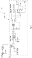
- Fig. 2 shows a circuit diagram of the power conversion topology 1 according to the invention in a first embodiment.
- the power conversion topology 1 contains a three-winding transformer 8 with a primary winding 8a for connection to the utility grid 3, a secondary winding 8b for connection to the HV-battery 4 and a tertiary winding 8c for connection to the LV-battery 5.
- the primary winding 8a, the secondary winding 8b, and the tertiary winding 8c electromagnetically interact with each other.
- the HV-battery 4 and the LV-battery 5 are not part of the power conversion topology 1 according to the invention.
- the power conversion topology 1 comprises a GR-rectifier 9 and the GR-capacitor 7.
- the GR-rectifier 9 is connected upstream of the primary winding 8a, and the GR-capacitor 7 is connected upstream of the GR-rectifier 9.
- the power conversion topology 1 further comprises a HV-rectifier 10, a HV-filter 11, and a HV-capacitor 12.
- the HV-rectifier 10 is connected downstream of the secondary winding 8b, and the HV-filter 11 is connected downstream of the HV-rectifier 10.
- the HV-capacitor 11 is connected between the HV-rectifier 10 and the HV-filter 12.
- the HV-rectifier 10, the HV-filter 11 and the HV-capacitor 12 are thereby connected in parallel.
- the power conversion topology 1 also contains an LV-rectifier 13 and an LV-filter 14.
- the LV-rectifier 13 is connected downstream of the tertiary winding 8b, and the LV-filter 14 is connected downstream of the LV-rectifier 13.
- An auxiliary inductor 15 is connected between the LV-rectifier 13 and the LV-filter 14 in series therewith.
- the power conversion topology 1 contains a blocking circuit 16 with a transformer 17 and a diode 18.
- the blocking circuit 16 is connected between the auxiliary inductor 15 and the HV-capacitor 12.
- the blocking circuit 16 can also be connected between the auxiliary inductor 15 and the GR-capacitor 7. In the following, however, only the shown connection of the blocking circuit 16 will be discussed.
- the GR-rectifier 9 and the HV-rectifier 10 are each represented by a full bridge rectifier.
- the LV-rectifier 13 is represented by a midpoint rectifier with a center tap 19 and two active switches 20a and 20b.
- the HV-filter 11 and the LV-filter 14 are realized in a manner known to those skilled in the art.
- the GR-capacitor 7 has a voltage V_DC
- the HV-capacitor 12 has a voltage V_C_HV
- the HV-battery 4 has a voltage V_HV
- the LV-battery 5 has a voltage V_LV.
- the auxiliary inductor 15 has an inductance L_LV
- the GR-capacitor 7 has a capacitance C_DC
- the HV-capacitor 12 has a capacitance C_HV.
- the primary winding 8a has a turns number N_DC and the secondary winding 8b has a turns number N_HV. Due to the structure of the LV-rectifier 13, the tertiary winding 8c is divided into two partial windings each have a turns number N_LV.
- a turns number of a LV-sided winding of the transformer 17 is a reference turns number and is set equal to one. However, it is understood that this may be arbitrary.
- a turns number of a HV-sided winding of the transformer 17 is N_START. Accordingly, the transformer 17 has a winding ratio N_TRANS equal to N_START/1.
- the power conversion topology 1 can be operated in a CHARGE mode, in a DRIVE mode, in a V-TO-G mode and in a PRECHARGE mode.
- the power conversion topology 1 is connected to the utility grid 3.
- the HV-battery 4 and the LV-battery 5 of the electric vehicle 2 are charged by the utility grid 3.
- the power conversion topology 1 is disconnected from the utility grid 3 and the LV-battery 5 is charged by the HV-battery 4 of the electric vehicle 2.
- the power conversion topology 1 In the V-TO-G mode, the power conversion topology 1 is connected to the utility grid 3 and the utility grid 3 draws a current from the HV-battery 4 of the electric vehicle 2.
- the power conversion topology 1 In the PRECHARGE mode, the power conversion topology 1 is disconnected from the utility grid 3 and the GR-capacitor 7 and the HV-capacitor 12 are charged with a current i_LV_batt provided by the LV-battery 5.
- the PRECHARGE mode of method 21 will be explained in more detail below with reference to Figs. 3-9 .
- Fig. 3 shows a circuit diagram of the power conversion topology 1 according to the invention in the first embodiment in the PRECHARGE mode.
- the power conversion topology 1 is disconnected from the utility grid 3 and the GR-capacitor 7 and the HV-capacitor 12 are charged by the LV-battery 5.
- the components not used in the PRECHARGE mode - here HV-filter 11 and the HV-battery 5 - are hidden.
- a BUCK mode and a BOOST mode can be executed.
- the two switches 20a and 20b of the LV-rectifier 13 are operated in a complementary manner with a duty cycle D between 0% and 50% in each case.
- the diode 18 of the blocking circuit 16 is switched off.
- Current flows from the LV-battery 5 through the LV-filter 14 and the auxiliary inductor 15 to the center tap 19 and through one of the partial turns of the tertiary winding 8c.
- the current is further passed through the GR-rectifier 7 and the HV-rectifier 10, where the GR-rectifier 7 and the HV-rectifier 10 operate as simple diode rectifiers.
- the GR-capacitor 7 and the HV-capacitor 12 are charged.
- the diode 18 is switched on and no current flows into the center tap 19.
- a high current flows to charge the HV-capacitor 12.
- the HV-capacitor 12 is charged in both time intervals and the GR-capacitor is charged in only one of the time intervals. If the turns numbers N_DC and N_HV are nearly equal, the HV-capacitor 12 is charged faster than the GR-capacitor 7, even if the capacitance C_HV of the HV-capacitor 12 is much higher than the capacitance C_DC of the GR-capacitor 7.
- V_ C_ HV 2 ⁇ N _ HV / N _ LV ⁇ D ⁇ V _ LV
- V _ C _ HV _ max N _ HV / N _ LV ⁇ V _ LV
- the current i_push_pull in the center tap 19 is discontinuous in BUCK mode. At high power, it is practically a pulsed current.
- the switches 20a and 20b are controlled with a duty cycle D between 50% and 100% in each case and thus with a phase shift of 180° and a time overlap.
- the BOOST mode can be used to achieve a voltage V_C_HV greater than the maximum voltage V_C_HV_max achievable in the BUCK mode.
- the GR-rectifier 9 and the HV-rectifier 10 then operate as simple diode rectifiers.
- the current i_push_pull in the center tap 19 is continuous and may be of a triangular shape.
- Fig. 4 shows a circuit diagram of the power conversion topology 1 according to the invention in the first embodiment in the BUCK mode of the PRECHARGE mode with a PCMC controller 22.
- the components not used in the PRECHARGE mode - here HV-filter 11 and the HV-battery 5 - are hidden.
- a signal generator circuit 23 of the PCMC controller 22 is shown.
- a PCMC circuit 24 of the PCMC controller 22 is shown in Fig. 6 .
- the signal generator circuit 23 includes a GR-AC current transformer 25a which is connected between the GR-rectifier 9 and the primary winding 8a and has a turns ratio N_DC/1.
- the signal generator circuit 23 includes a HV-AC current transformer 25b which is connected between the secondary winding 8b and the HV-rectifier 10 and has a turns ratio N_HV/1.
- the signal generator circuit 23 comprises an RF current rectifier 26a and a resistor 27a having a resistance value R_DC.
- the RF current rectifier 26a and the resistor 27a are connected in parallel with the GR-AC current transformer 25a.
- the signal generator circuit 23 comprises a RF current rectifier 26b and a resistor 27b having a resistance value R_HV.
- the RF current rectifier 26b and the resistor 27b are connected in parallel with the HV-AC current transformer 25b.
- the signal generator circuit 23 thereby synthesizes a voltage signal V_SN for the PCMC circuit 24 in Fig. 6 in the form of the current i_push_pull flowing in the center tap 19 from alternating currents at the two AC current transformers 25a and 25b.
- Fig. 5 shows a circuit diagram of the power conversion topology 1 according to the invention in the first embodiment in the BUCK mode of the PRECHARGE mode with the deviated signal generator circuit 23 of the PCMC controller 22.
- the signal generator circuit 23 includes a GR-current converter 28a connected between the GR-capacitor 7 and the GR-rectifier 9 and having a turns ratio N_S_DC/1, and a HV-current converter 28b connected between the HV-rectifier 10 and the HV-capacitor 12 and having a turns ratio N_S_HV/1.
- the signal generator circuit 23 contains two resistors 29a and 29b and two diodes 30a and 30b.
- the resistors 29a and 29b have resistance values R_S_DC and R_S_HV, respectively.
- the signal generator circuit 23 synthesizes the voltage signal V_SN for the PCMC circuit 23 in the form of the current i_push_pull flowing in the center tap 19 from demagnetized currents at the two current transformers 28a and 28b.
- Fig. 6 shows a circuit diagram of the PCMC circuit 24 of the PCMC controller 22 of Fig. 4 and Fig. 5 .
- V_SE represents an external stabilization ramp voltage signal added to stabilize the voltage signal V_SN. This may be necessary especially due to a large variation of the voltage V_C_HV in the PRECHARGE mode.
- the voltage signal V_C is a control voltage that limits a momentary value of the combined voltage signals V_SN and V_SE.
- the PCMC circuit 24 generates voltage signals DRIVE_20a and DRIVE_20b to control the switches 20a and 20b of the LV-rectifier 13.
- the current i_push_pull flowing in the center tap 19 and the currents at the switches 20a and 20b of the LV-rectifier 13 can be limited in the BUCK mode of the PRECHARGE mode.
- Fig. 7 shows a circuit diagram of the PCMC controller 22 with a proportional-integral controller 31.
- the proportional-integral controller 31 generates the voltage signal V_C for the PCMC circuit 24, which is between a measured voltage value V_C_HV of the HV-capacitor 12 and a predetermined target voltage value V_C_HV* of the HV-capacitor 12.
- the proportional-integral controller 31 may be implemented with analog circuitry or digitally.
- Fig. 8 shows a circuit diagram of the PCMC controller 22 of Fig. 7 during a health test.
- a current i_LV_batt is drawn from LV-battery 4 and the health status of LV-battery 4 is checked.
- already existing PCMC controller 22 is used so that the health test can be performed in the BUCK mode of the PRECHARGE mode without additional components.
- Fig. 9 shows a circuit diagram of the power conversion topology 1 according to the invention in a second embodiment in the PRECHARGE mode.
- the components not used in the PRECHARGE mode - here HV-filter 11 and the HV-battery 5 - are hidden.
- the LV-rectifier 13 is designed here as a full-bridge boost converter.
Landscapes
- Engineering & Computer Science (AREA)
- Power Engineering (AREA)
- Transportation (AREA)
- Mechanical Engineering (AREA)
- Life Sciences & Earth Sciences (AREA)
- Sustainable Development (AREA)
- Sustainable Energy (AREA)
- Dc-Dc Converters (AREA)
Abstract
Description
- The invention relates to a power conversion topology for charging a HV-battery and/or a LV-battery of an electric vehicle according to the generic term of
claim 1. The invention also relates to a method for operating the power conversion topology. - An electric vehicle usually comprises an HV-battery (HV: high voltage) for supplying energy to a vehicle drive of the electric vehicle and an LV-battery (LV: low voltage) for supplying energy to other electrical consumers of the electric vehicle - for example the instrument panel and/or lamps. The HV-battery i.e. the HV-side of the electric vehicle must be electrically isolated from the LV-battery i.e. LV-side of the electric vehicle. The HV-battery is usually charged via a utility grid and the LV-battery via the HV-battery. In addition, the utility grid can be supplied with stored energy from the HV-battery i.e. the HV-battery can be discharged into the utility grid. In addition, the HV-battery can be precharged via the LV-battery. The above functions are implemented by a power conversion topology that electrically connects the utility grid, the HV-battery and the LV-battery accordingly. To realize the precharging of the HV-battery from the LV-battery in the power conversion topology, high currents must be drawn from the LV-battery. These currents can be dangerous. To be able to control or limit these currents, the power conversion topology must be implemented accordingly. However, measuring the instantaneous currents at the LV-battery i.e. at the LV-side of the electric vehicle can be very complex and cost-intensive. Accordingly, the power conversion topology is also complex and cost-intensive in design.
- A power conversion topology is known, for example, from
WO/2019/199964 A1 . - It is therefore the object of the invention to provide an improved or at least alternative embodiment for a power conversion topology of the generic type in which the described disadvantages are overcome. It is also the object of the invention to provide a corresponding method for operating the power conversion topology.
- This object is solved according to the invention by the object of the independent claims. Advantageous embodiments are the subject of the dependent claims.
- A power conversion topology is provided for charging a HV-battery and/or a LV-battery of an electric vehicle. The power conversion topology comprises a three-winding transformer with a primary winding for connection to a utility grid, a secondary winding for connection to the HV-battery and a tertiary winding for connection to the LV-battery. The primary winding, the secondary winding, and the tertiary winding interact electromagnetically with each other. The power conversion topology also contains a GR-rectifier and a GR-capacitor. The GR-rectifier is connected upstream of the primary winding and the GR-capacitor is connected upstream of the GR-rectifier. The power conversion topology further comprises a HV-rectifier, a HV-filter, and a HV-capacitor. The HV-rectifier is connected downstream of the secondary winding and the HV-filter is connected downstream of the HV-rectifier. The HV-capacitor is then connected between the HV-rectifier and the HV-filter. The power conversion topology also comprises an LV-rectifier and an LV-filter. The LV-rectifier is connected downstream of the tertiary winding and the LV-filter is connected downstream of the LV-rectifier. According to the invention, the power conversion topology contains an auxiliary inductor connected between the LV-rectifier and the LV-filter. In addition, the power conversion topology contains a blocking circuit comprising a transformer and a diode. Here, the blocking circuit is connected between the auxiliary inductor and the GR-capacitor or between the auxiliary inductor and the HV-capacitor.
- In the present invention, abbreviations "HV" for "high voltage" and "LV" for "low voltage" are used. An element of the power conversion topology marked with the abbreviation "HV" or "LV" is assigned to an HV-side or an LV-side of the power conversion topology, respectively. Furthermore, the abbreviation "GR" is used for "utility grid". An element of the power conversion topology marked with the abbreviation "GR" is correspondingly assigned to a GR-side i.e. a side of the power conversion topology assigned to the utility grid. It is understood that all elements of the power conversion topology are designed and interconnected to perform the functions described below. The terms "upstream" and "downstream" refer to the direction of current from the utility grid to the primary winding on the GR-side, the direction of current from the secondary winding to the HV-battery on the HV-side, and the direction of current from the tertiary winding to the LV-battery on the LV-side.
- Advantageously, the power conversion topology according to the invention can be operated in a CHARGE mode, in a DRIVE mode and in a V-TO-G mode. In the CHARGE mode, the power conversion topology is connected to the utility grid and the HV-battery and the LV-battery of the electric vehicle are charged by the utility grid. In a DRIVE mode, the power conversion topology is disconnected from the utility grid and the LV-battery of the electric vehicle is charged by the HV-battery of the electric vehicle. In the V-TO-G mode, the power conversion topology is connected to the utility grid and the utility grid draws a current from the HV-battery of the electric vehicle.
- The proposed blocking circuit also allows the power conversion topology according to the invention to be operated in a PRECHARGE mode. In the PRECHARGE mode, the power conversion topology is disconnected from the utility grid and the GR-capacitor and the HV-capacitor are charged by the LV-battery. Thereby, in the PRECHARGE mode, the GR-capacitor and the HV-capacitor can be first discharged by the blocking circuit within a short time, preferably less than within one second, and then recharged within a short time. To charge the GR-capacitor and the HV-capacitor, a current is drawn from the LV-battery.
- The blocking circuit is connected in parallel to the GR-capacitor or to the HV-capacitor and connects the GR-side of the power conversion topology or the HV-side of the power conversion topology to the LV-side of the power conversion topology. In the blocking circuit, the transformer is connected in parallel to the auxiliary inductor. The auxiliary inductor itself may be connected in series with the LV-rectifier and the LV-filter. The diode of the blocking circuit is arranged between the transformer and the GR-capacitor or the HV-capacitor and is connected in series with the GR-capacitor or the HV-capacitor. The blocking circuit is designed and connected in the power conversion topology such that it carries a current only in the PRECHARGE mode. In the CHARGE mode, in the DRIVE mode and in the V-TO-G mode, the diode of the blocking circuit is switched off and no current is applied to the winding of the transformer of the blocking circuit assigned to the GR-side or HV-side.
- In the PRECHARGE mode, a high current can be drawn from the LV-battery and peak currents can be limited. In particular, the RMS value of the current through the LV-capacitor as well as the peak value of the current through the tertiary winding of the three-winding transformer can be greatly reduced. In addition, the control of the power flows between the GR-side, the HV-side and the LV-side can be simplified.
- In the power conversion topology, the three-winding transformer is used, which means that only one transformer is used compared to conventional power conversion topology. This can reduce the size and cost of the entire power conversion topology and increase the overall power density. In addition, the three-winding transformer enables galvanic isolation between the HV-side and the LV-side of the electric vehicle.
- The auxiliary inductor may be a magnetizing inductance of the blocking circuit transformer and may be realized by a winding of the transformer. The GR-rectifier may be represented by a full bridge rectifier and the HV-rectifier may be represented by a full bridge rectifier. The LV-rectifier may be represented by a full-bridge boost converter or by a midpoint rectifier with two active switches.
- The invention also relates to a method of operating the power conversion topology described above. The power conversion topology is thereby operable in a PRECHARGE mode, wherein in the PRECHARGE mode the power conversion topology is disconnected from the utility grid and the GR-capacitor and the HV-capacitor are discharged and subsequently charged by the LV-battery. Thereby, in the PRECHARGE mode, the GR-capacitor and the HV-capacitor are first fully discharged and then charged with the current drawn from the LV-battery. The GR-rectifier and the HV-rectifier can thereby be controlled in the PRECHARGE mode to operate as diode rectifiers. The PRECHARGE mode can be carried out in particular before the DRIVE mode.
- In the power conversion topology, the characteristics of the blocking circuit transformer and the three-winding transformer can be matched to each other. A turns number of the primary winding, a turns number of the secondary winding and a turns number of the tertiary winding of the three-winding transformer can be predetermined as a function of the turns ratio of the blocking circuit transformer. If the blocking circuit is connected between the auxiliary inductor and the GR-capacitor, the turns ratio of the transformer of the blocking circuit may correspond to a ratio of the turns number of the primary winding and the turns number of the tertiary winding. If the blocking circuit is connected between the auxiliary inductor and the HV-capacitor, the turns ratio of the transformer of the blocking circuit may correspond to a ratio of the turns number of the secondary winding and the turns number of the tertiary winding. In this case, the turns ratio of the transformer is determined by a ratio of a turns number of a winding facing the GR-side or HV-side and a turns number of a winding facing the LV-side. The turns number of the winding facing the LV-side can be used as a reference turns number. If the reference turns number is given, the turns number of the winding facing the GR-side or HV-side i.e. the winding ratio of the transformer can be determined. Based on it, the turns number of the primary winding and/or the turns number of the secondary winding and/or the turns number of the tertiary winding of the three-winding transformer can be determined. The exact turns number of the winding of the transformer facing the LV-side i.e. the reference turn number is left to those skilled in the art.
- In a preferred embodiment of the power conversion topology, the LV-rectifier is represented by a midpoint rectifier with two active switches. As discussed above, the GR-rectifier and the HV-rectifier may each be represented by a full bridge rectifier. In this case, the PRECHARGE mode contains a BUCK mode, where in the BUCK mode, the two switches of the LV-rectifier are operated in a complementary manner with a duty cycle between 0 and 0.5 i.e. between 0% and 50% in each case. As soon as one of the two switches is switched on, the diode of the blocking circuit is switched off and the GR-capacitor and the HV-capacitor are charged. As soon as both switches are switched off, the diode of the blocking circuit is switched on and the GR-capacitor or HV-capacitor is charged. Whether the GR-capacitor or the HV-capacitor is charged depends on the design of the power conversion topology. If the blocking circuit is connected between the auxiliary inductor and the GR-capacitor, the HV-capacitor is charged in one time interval and the GR-capacitor is charged in both time intervals. If the blocking circuit is connected between the auxiliary inductor and the HV-capacitor, the GR-capacitor is charged in one time interval and the HV-capacitor is charged in both time intervals. The current flowing in the center tap of the LV-rectifier is thereby discontinuous and can practically be a pulsed current at a high power.
- If the blocking circuit is connected between the auxiliary inductor and the GR-capacitor, a maximum voltage applied to the GR-capacitor in the BUCK mode of the PRECHARGE mode corresponds to a product of the ratio of the turns number of the primary winding and the turns number of the tertiary winding and a voltage provided by the LV-battery. A voltage applied to the GR-capacitor is then equal to twice the product of the maximum voltage applied to the GR-capacitor and the duty cycle. If the blocking circuit is connected between the auxiliary inductor and the HV-capacitor, a maximum voltage applied to the HV-capacitor in the BUCK mode of the PRECHARGE mode corresponds to a product of the ratio of the turns number of the secondary winding and the turns number of the tertiary winding and a voltage provided by the LV-battery. A voltage applied to the HV-capacitor then corresponds to a double product of the maximum voltage applied to the HV-capacitor and the duty cycle.
- In addition, it may be provided that in the BUCK mode of the PRECHARGE mode, a PCMC controller (PCMC: peak current mode control) is used to control a current flowing in a center tap of the LV-rectifier i.e. the midpoint rectifier. The PCMC controller contains a PCMC circuit and a signal generator circuit. The signal generator circuit thereby contains a GR-AC current transformer and a HV-AC current transformer. The GR-AC current transformer is connected between the GR-rectifier and the primary winding, and the HV-AC current transformer is connected between the secondary winding and the HV-rectifier. Here, the signal generator circuit synthesizes a voltage signal for the PCMC circuit in the form of the current flowing in the center tap of the midpoint rectifier from alternating currents at the two HV-AC current transformers. Then, the PCMC circuit generates voltage signals to control the switches of the LV-rectifier i.e. the midpoint rectifier based on the synthesized voltage signal. The signal generator circuit may contain other components - for example, RF current rectifiers (RF: High Frequency) and resistors.
- The current flowing in the center tap contains high peak values and its measurement can be complex. Through PCMC controller, the current flowing in the center tap of the LV-rectifier i.e. the midpoint rectifier can be reconstructed from the alternating currents at the two AC current transformers. The currents at the two AC current transformers are comparatively small and thus the current flowing in the center tap can be measured in a comparatively simplified manner. This eliminates the need for expensive components required to measure the current flowing in the center tap, thereby reducing the cost of the power conversion topology.
- Alternatively, a differently designed PCMC controller can be used to control a current flowing in a center tap of the LV-rectifier i.e. the midpoint rectifier in the BUCK mode of the PRECHARGE mode. In this regard, the PCMC controller may include a PCMC circuit and a signal generator circuit. The signal generator circuit then comprises a GR-current transformer connected between the GR-capacitor and the GR-rectifier, and an HV-current transformer connected between the HV-rectifier and the HV-capacitor. The signal generator circuit can then synthesize a voltage signal in the form of the current flowing in the center tap of the LV-rectifier i.e. midpoint rectifier from demagnetized currents at the two current transformers, and the PCMC circuit can then generate voltage signals for controlling the switches of the LV-rectifier i.e. the midpoint rectifier from the synthesized voltage signal. The signal generator circuit may also include other components - for example, resistors or diodes. Analogous to the PCMC controller embodiment described above, the current flowing in the center tap of the LV-rectifier i.e. midpoint rectifier can be reconstructed here from the currents at the two current transformers. Since the currents at the two current transformers are small compared to the current flowing in the center tap, effort and cost can be reduced.
- In addition, the PCMC controller may include a proportional-integral controller. The proportional-integral controller can then generate a control voltage signal between a measured voltage value of the HV-capacitor and a predetermined desired voltage value of the HV-capacitor. Based on the control voltage signal, the PCMC circuit can then generate the voltage signals to control the switches of the LV-rectifier i.e. the midpoint rectifier. The proportional-integral controller can be implemented with analog circuits or digitally.
- In addition, it can be provided that a health test of the LV-battery is carried out in the PRECHARGE mode. In the health test, a current can be drawn from the LV-battery by the PCMC controller and regulated to the required value. The current is sampled and evaluated over a predetermined time interval. Based on this evaluation, the health status of the LV-battery can be assessed. Advantageously, the health test can be carried out in the PRECHARGE mode with the PCMC controller without further additional components.
- In a preferred embodiment of the power conversion topology, the LV-rectifier is represented by a midpoint rectifier with two active switches. The PRECHARGE mode then contains a BOOST mode, where in the BOOST mode, the two switches are operated in a complementary manner with a duty cycle between 0.5 and 1 i.e. between 50% and 100% in each case. In the BOOST mode, the two switches can be driven with a phase shift of 180° and a time overlap. As soon as one of the two switches is switched on, the GR-capacitor and the HV-capacitor are charged. As soon as two switches are switched off, partial turns of the tertiary winding formed by a center tap of the LV-rectifier are short-circuited and the GR-capacitor and HV-capacitor are not charged. The BOOST mode may be required if a voltage on the GR-capacitor or on the HV-capacitor should be reached which is higher than the maximum voltage on the GR-capacitor or HV-capacitor achievable in the BUCK mode of the PRECHARGE mode. The current flowing in the center tap of the LV-rectifier i.e. the midpoint rectifier is continuous and may be of a triangular shape.
- Additionally, it may be provided that in the BOOST mode of the PRECHARGE mode, an ACMC controller (ACMC: Average Current Mode Control) is used to control a current flowing in a center tap of the midpoint rectifier. The ACMC controller can thereby operates with a current provided by the LV-battery. Voltage signals to control the switches of the LV-rectifier i.e. the midpoint rectifier may be generated from the named current. The current provided by the LV-battery is thereby approximately a direct current.
- As explained above, the power conversion topology can also be operated in a CHARGE mode, in a DRIVE mode, and in a V-TO-G mode. In the CHARGE mode, the power conversion topology is connected to the utility grid. In the CHARGE mode, the HV-battery and the LV-battery of the electric vehicle are charged by the utility grid. In the DRIVE mode, the power conversion topology is disconnected from the utility grid and the LV-battery of the electric vehicle is charged by the HV-battery of the electric vehicle. In the V-TO-G mode, the power conversion topology is connected to the utility grid and the utility grid draws a current from the HV-battery of the electric vehicle. The blocking circuit can be designed and connected in the power conversion topology in such a way that it carries a current only in the PRECHARGE mode. In the CHARGE mode, in the DRIVE mode and in the V-TO-G mode, the diode of the blocking circuit is switched off and no current is applied to the winding of the transformer facing the GR-side or the HV-side.
- Further important features and advantages of the invention are apparent from the subclaims, from the drawings, and from the accompanying figure description based on the drawings.
- It is understood that the above features and those to be explained below can be used not only in the combination indicated in each case, but also in other combinations or on their own, without departing from the scope of the present invention.
- Preferred embodiments of the invention are shown in the drawings and will be explained in more detail in the following description, wherein identical reference signs refer to identical or similar or functionally identical components.
- It shows, each schematically
- Fig. 1
- a circuit diagram of a power conversion topology according to the invention in an electric vehicle;
- Fig. 2
- a circuit diagram of the power conversion topology according to the invention in a first embodiment;
- Fig. 3
- a circuit diagram of the power conversion topology according to the invention in the first embodiment in a PRECHARGE mode;
- Fig. 4
- a circuit diagram of the power conversion topology according to the invention in the first embodiment in PRECHARGE mode with a signal generator circuit of a PCMC controller;
- Fig. 5
- a circuit diagram of the power conversion topology according to the invention in the first embodiment in a PRECHARGE mode with a deviating signal generator circuit of the PCMC controller;
- Fig. 6
- a circuit diagram of a PCMC circuit of the PCMC controller of
Fig. 4 andFig. 5 ; - Fig. 7
- a circuit diagram of the PCMC controller with a different signal generator circuit;
- Fig. 8
- a circuit diagram of the PCMC controller of
Fig. 7 during a health test; - Fig. 9
- a circuit diagram of the power conversion topology according to the invention in a second embodiment in the PRECHARGE mode.
-
Fig. 1 shows a circuit diagram of apower conversion topology 1 according to the invention in anelectric vehicle 2. Here, thepower conversion topology 1 is electrically connected to autility grid 3, to an HV-battery 4 of theelectric vehicle 2 and to an LV-battery 5 of theelectric vehicle 2. A PFC filter 6 (PFC: power factor correction) is connected between theutility grid 3 and thepower conversion topology 1. In addition, a GR-capacitor 7 is connected downstream of thePFC filter 6. Theutility grid 3, thePFC filter 6, the HV-battery 4 and the LV-battery 5 are not part of thepower conversion topology 1 according to the invention. Furthermore, theutility grid 3 is not part of theelectric vehicle 2. -
Fig. 2 shows a circuit diagram of thepower conversion topology 1 according to the invention in a first embodiment. Here, thepower conversion topology 1 contains a three-windingtransformer 8 with a primary winding 8a for connection to theutility grid 3, a secondary winding 8b for connection to the HV-battery 4 and a tertiary winding 8c for connection to the LV-battery 5. The primary winding 8a, the secondary winding 8b, and the tertiary winding 8c electromagnetically interact with each other. As explained above, the HV-battery 4 and the LV-battery 5 are not part of thepower conversion topology 1 according to the invention. - The
power conversion topology 1 comprises a GR-rectifier 9 and the GR-capacitor 7. The GR-rectifier 9 is connected upstream of the primary winding 8a, and the GR-capacitor 7 is connected upstream of the GR-rectifier 9. Thepower conversion topology 1 further comprises a HV-rectifier 10, a HV-filter 11, and a HV-capacitor 12. The HV-rectifier 10 is connected downstream of the secondary winding 8b, and the HV-filter 11 is connected downstream of the HV-rectifier 10. The HV-capacitor 11 is connected between the HV-rectifier 10 and the HV-filter 12. The HV-rectifier 10, the HV-filter 11 and the HV-capacitor 12 are thereby connected in parallel. Thepower conversion topology 1 also contains an LV-rectifier 13 and an LV-filter 14. The LV-rectifier 13 is connected downstream of the tertiary winding 8b, and the LV-filter 14 is connected downstream of the LV-rectifier 13. Anauxiliary inductor 15 is connected between the LV-rectifier 13 and the LV-filter 14 in series therewith. - In addition, the
power conversion topology 1 contains a blockingcircuit 16 with atransformer 17 and adiode 18. Here, the blockingcircuit 16 is connected between theauxiliary inductor 15 and the HV-capacitor 12. Alternatively, the blockingcircuit 16 can also be connected between theauxiliary inductor 15 and the GR-capacitor 7. In the following, however, only the shown connection of the blockingcircuit 16 will be discussed. - In the first embodiment of the
power conversion topology 1, the GR-rectifier 9 and the HV-rectifier 10 are each represented by a full bridge rectifier. The LV-rectifier 13 is represented by a midpoint rectifier with acenter tap 19 and twoactive switches filter 11 and the LV-filter 14 are realized in a manner known to those skilled in the art. - In the
power conversion topology 1, the GR-capacitor 7 has a voltage V_DC, the HV-capacitor 12 has a voltage V_C_HV, the HV-battery 4 has a voltage V_HV, and the LV-battery 5 has a voltage V_LV. Theauxiliary inductor 15 has an inductance L_LV, the GR-capacitor 7 has a capacitance C_DC, and the HV-capacitor 12 has a capacitance C_HV. - The primary winding 8a has a turns number N_DC and the secondary winding 8b has a turns number N_HV. Due to the structure of the LV-
rectifier 13, the tertiary winding 8c is divided into two partial windings each have a turns number N_LV. Here, a turns number of a LV-sided winding of thetransformer 17 is a reference turns number and is set equal to one. However, it is understood that this may be arbitrary. A turns number of a HV-sided winding of thetransformer 17 is N_START. Accordingly, thetransformer 17 has a winding ratio N_TRANS equal to N_START/1. - The characteristics of the
transformer 17 of the blockingcircuit 16 and of the three-windingtransformer 8 are matched to each other. The following relationship applies:
- In a
method 21 according to the invention, thepower conversion topology 1 can be operated in a CHARGE mode, in a DRIVE mode, in a V-TO-G mode and in a PRECHARGE mode. In the CHARGE mode, thepower conversion topology 1 is connected to theutility grid 3. In this case, the HV-battery 4 and the LV-battery 5 of theelectric vehicle 2 are charged by theutility grid 3. In the DRIVE mode, thepower conversion topology 1 is disconnected from theutility grid 3 and the LV-battery 5 is charged by the HV-battery 4 of theelectric vehicle 2. In the V-TO-G mode, thepower conversion topology 1 is connected to theutility grid 3 and theutility grid 3 draws a current from the HV-battery 4 of theelectric vehicle 2. In the PRECHARGE mode, thepower conversion topology 1 is disconnected from theutility grid 3 and the GR-capacitor 7 and the HV-capacitor 12 are charged with a current i_LV_batt provided by the LV-battery 5. The PRECHARGE mode ofmethod 21 will be explained in more detail below with reference toFigs. 3-9 . -
Fig. 3 shows a circuit diagram of thepower conversion topology 1 according to the invention in the first embodiment in the PRECHARGE mode. In the PRECHARGE mode, thepower conversion topology 1 is disconnected from theutility grid 3 and the GR-capacitor 7 and the HV-capacitor 12 are charged by the LV-battery 5. For clarity, the components not used in the PRECHARGE mode - here HV-filter 11 and the HV-battery 5 - are hidden. In the PRECHARGE mode, a BUCK mode and a BOOST mode can be executed. - In the BUCK mode, the two
switches rectifier 13 are operated in a complementary manner with a duty cycle D between 0% and 50% in each case. As soon as one of the twoswitches diode 18 of the blockingcircuit 16 is switched off. Current flows from the LV-battery 5 through the LV-filter 14 and theauxiliary inductor 15 to thecenter tap 19 and through one of the partial turns of the tertiary winding 8c. The current is further passed through the GR-rectifier 7 and the HV-rectifier 10, where the GR-rectifier 7 and the HV-rectifier 10 operate as simple diode rectifiers. Here, the GR-capacitor 7 and the HV-capacitor 12 are charged. As soon as the twoswitches diode 18 is switched on and no current flows into thecenter tap 19. As a result, a high current flows to charge the HV-capacitor 12. - The HV-
capacitor 12 is charged in both time intervals and the GR-capacitor is charged in only one of the time intervals. If the turns numbers N_DC and N_HV are nearly equal, the HV-capacitor 12 is charged faster than the GR-capacitor 7, even if the capacitance C_HV of the HV-capacitor 12 is much higher than the capacitance C_DC of the GR-capacitor 7. Here, the following relationship applies to the voltage V_C_HV and the maximum voltage V_C_HV_max on the HV-capacitor 12:

- The current i_push_pull in the
center tap 19 is discontinuous in BUCK mode. At high power, it is practically a pulsed current. - In the BOOST mode, the
switches switches tertiary turn 8c are short-circuited and no current flows to the GR-capacitor 7 and the HV-capacitor 12. As soon as one of the twoswitches capacitor 7 and the HV-capacitor 12 via the GR-rectifier 9 and the HV-rectifier 10 and they are charged. The GR-rectifier 9 and the HV-rectifier 10 then operate as simple diode rectifiers. The current i_push_pull in thecenter tap 19 is continuous and may be of a triangular shape. -
Fig. 4 shows a circuit diagram of thepower conversion topology 1 according to the invention in the first embodiment in the BUCK mode of the PRECHARGE mode with a PCMC controller 22. For clarity, the components not used in the PRECHARGE mode - here HV-filter 11 and the HV-battery 5 - are hidden. InFig. 4 , only a signal generator circuit 23 of the PCMC controller 22 is shown. A PCMC circuit 24 of the PCMC controller 22 is shown inFig. 6 . Here, the signal generator circuit 23 includes a GR-ACcurrent transformer 25a which is connected between the GR-rectifier 9 and the primary winding 8a and has a turns ratio N_DC/1. In addition, the signal generator circuit 23 includes a HV-ACcurrent transformer 25b which is connected between the secondary winding 8b and the HV-rectifier 10 and has a turns ratio N_HV/1. On the GR-side, the signal generator circuit 23 comprises an RFcurrent rectifier 26a and aresistor 27a having a resistance value R_DC. The RFcurrent rectifier 26a and theresistor 27a are connected in parallel with the GR-ACcurrent transformer 25a. On the HV-side, the signal generator circuit 23 comprises a RFcurrent rectifier 26b and aresistor 27b having a resistance value R_HV. The RFcurrent rectifier 26b and theresistor 27b are connected in parallel with the HV-ACcurrent transformer 25b. The signal generator circuit 23 thereby synthesizes a voltage signal V_SN for the PCMC circuit 24 inFig. 6 in the form of the current i_push_pull flowing in thecenter tap 19 from alternating currents at the two ACcurrent transformers -
Fig. 5 shows a circuit diagram of thepower conversion topology 1 according to the invention in the first embodiment in the BUCK mode of the PRECHARGE mode with the deviated signal generator circuit 23 of the PCMC controller 22. For clarity, the components not used in the PRECHARGE mode - here HV-filter 11 and the HV-battery 5 - are hidden. Here, the signal generator circuit 23 includes a GR-current converter 28a connected between the GR-capacitor 7 and the GR-rectifier 9 and having a turns ratio N_S_DC/1, and a HV-current converter 28b connected between the HV-rectifier 10 and the HV-capacitor 12 and having a turns ratio N_S_HV/1. In addition, the signal generator circuit 23 contains tworesistors diodes 30a and 30b. Here, theresistors center tap 19 from demagnetized currents at the twocurrent transformers -
Fig. 6 shows a circuit diagram of the PCMC circuit 24 of the PCMC controller 22 ofFig. 4 andFig. 5 . Here, V_SE represents an external stabilization ramp voltage signal added to stabilize the voltage signal V_SN. This may be necessary especially due to a large variation of the voltage V_C_HV in the PRECHARGE mode. The voltage signal V_C is a control voltage that limits a momentary value of the combined voltage signals V_SN and V_SE. The PCMC circuit 24 generates voltage signals DRIVE_20a and DRIVE_20b to control theswitches rectifier 13. With a suitable waveform of the voltage signal V_C, the current i_push_pull flowing in thecenter tap 19 and the currents at theswitches rectifier 13 can be limited in the BUCK mode of the PRECHARGE mode. -
Fig. 7 shows a circuit diagram of the PCMC controller 22 with a proportional-integral controller 31. The proportional-integral controller 31 generates the voltage signal V_C for the PCMC circuit 24, which is between a measured voltage value V_C_HV of the HV-capacitor 12 and a predetermined target voltage value V_C_HV* of the HV-capacitor 12. The proportional-integral controller 31 may be implemented with analog circuitry or digitally. -
Fig. 8 shows a circuit diagram of the PCMC controller 22 ofFig. 7 during a health test. In the health test, a current i_LV_batt is drawn from LV-battery 4 and the health status of LV-battery 4 is checked. For this purpose, already existing PCMC controller 22 is used so that the health test can be performed in the BUCK mode of the PRECHARGE mode without additional components. -
Fig. 9 shows a circuit diagram of thepower conversion topology 1 according to the invention in a second embodiment in the PRECHARGE mode. For clarity, the components not used in the PRECHARGE mode - here HV-filter 11 and the HV-battery 5 - are hidden. Deviating from the first embodiment of thepower conversion topology 1, the LV-rectifier 13 is designed here as a full-bridge boost converter.
Claims (15)
- Power conversion topology (1) for charging a HV-battery (4) and/or a LV-battery (5) of an electric vehicle (2),- wherein the power conversion topology (1) comprises a three-winding transformer (8) having a primary winding (8a) for connection to a utility grid (3), a secondary winding (8b) for connection to the HV-battery (4), and a tertiary winding (8c) for connection to the LV-battery (5),- wherein the power conversion topology (1) comprises a GR-rectifier (9) connected upstream of the primary winding (8a) and a GR-capacitor (7) connected upstream of the GR-rectifier (9);- wherein the power conversion topology (1) comprises an HV-rectifier (10) connected downstream of the secondary winding (8b), an HV-filter (11) connected downstream of the HV-rectifier (10), and an HV-capacitor (12) connected between the HV-rectifier (10) and the HV-filter (10);- wherein the power conversion topology (1) comprises an LV-rectifier (13) connected downstream of the tertiary winding (8c) and an LV-filter (14) connected downstream of the LV-rectifier (13);characterized in- that the power conversion topology (1) comprises an auxiliary inductor (15) connected between the LV-rectifier (13) and the LV-filter (14), and- in that the power conversion topology (1) comprises a blocking circuit (16) with a transformer (17) and a diode (18), the blocking circuit (16) being connected between the auxiliary inductor (15) and the GR-capacitor (7) or between the auxiliary inductor (15) and the HV-capacitor (12).
- Power conversion topology according to claim 1,
characterized in
that the auxiliary inductor (15) is a magnetizing inductance of the transformer (17) of the blocking circuit (16) and is realized by a winding of the transformer (17). - Power conversion topology according to claim 1 or 2,
characterized in- that the GR-rectifier (9) is represented by a full-bridge rectifier and/or the HV-rectifier (10) is represented by a full-bridge rectifier, and/or- that the LV-rectifier (13) is represented by a full-bridge boost converter or by a midpoint rectifier with two active switches (20a, 20b). - Method (21) for operating the power conversion topology (1) according to any one of the preceding claims,
characterized in
that the power conversion topology (1) is operable in a PRECHARGE mode, wherein in the PRECHARGE mode the power conversion topology (1) is disconnected from the utility grid (3) and the GR-capacitor (7) and the HV-capacitor (12) are discharged and subsequently charged by the LV-battery (5). - Method of claim 4,
characterized in- that a turns number (N_DC) of the primary winding (8a), a turns number (N_HV) of the secondary winding (8b) and a turns number (N_LV) of the tertiary winding (8c) of the three-winding transformer (8) are predetermined as a function of the turns ratio (N_TRANS) of the transformer (17) of the blocking circuit (16), and- that, if the blocking circuit (16) is connected between the auxiliary inductor (15) and the GR-capacitor (7), the turns ratio (N_TRANS) of the transformer (17) of the blocking circuit (16) corresponds to a ratio of the turns number (N_DC) of the primary winding (8a) and the turns number (N_LV) of the tertiary winding (8c), or- that, if the blocking circuit (16) is connected between the auxiliary inductor (15) and the HV-capacitor (12), the turns ratio (N_TRANS) of the transformer (17) of the blocking circuit (16) corresponds to a ratio of the turns number (N_HV) of the secondary winding (8b) and the turns number (N_LV) of the tertiary winding (8c). - Method according to claim 4 or 5,
characterized in- that the LV-rectifier (13) is represented by a midpoint rectifier with two active switches (20a, 20b),- that the PRECHARGE mode contains a BUCK mode, wherein in the BUCK mode, the two switches (20a, 20b) are operated in a complementary manner with a duty cycle (D) greater than 0 and less than 0.5 in each case,- that, as soon as one of the two switches (20a, 20b) is switched on, the diode (18) of the blocking circuit (16) is switched off and the GR-capacitor (7) and the HV-capacitor (12) are charged, and- that, as soon as the two switches (20a, 20b) are switched off, the diode (18) of the blocking circuit (16) is switched on and the GR-capacitor (7) or HV-capacitor (12) is charged. - Method according to claims 5 and 6,
characterized in- that, if the blocking circuit (16) is connected between the auxiliary inductor (15) and the GR-capacitor (7), in the BUCK mode of the PRECHARGE mode, a maximum voltage (V_C_DC_max) applied to the GR-capacitor (7) corresponds to a product of the ratio of the turns number (N_DC) of the primary winding (8a) and the turns number (N_LV) of the tertiary winding (8c) and a voltage (V_LV) provided by the LV-battery (5), and- that, if the blocking circuit (16) is connected between the auxiliary inductor (15) and the HV-capacitor (12), in the BUCK mode of the PRECHARGE mode, a maximum voltage (V_C_HV_max) applied to the HV-capacitor (12) corresponds to a product of the ratio of the turns number (N_HV) of the secondary winding (8b) and the turns number (N_LV) of the tertiary winding (8c) and a voltage (V_LV) provided by the LV-battery (5). - Method according to claims 5 and 6,
characterized in- that, if the blocking circuit (16) is connected between the auxiliary inductor (15) and the GR-capacitor (7), in the BUCK mode of the PRECHARGE mode, a voltage (V_C_DC) applied to the GR-capacitor (7) corresponds to a double product of a maximum voltage (V_C_DC_max) applied to the GR-capacitor (7) and the duty cycle (D), and- that, if the blocking circuit (16) is connected between the auxiliary inductor (15) and the HV-capacitor (12), in the BUCK mode of the PRECHARGE mode, a voltage (V_C_HV) applied to the HV-capacitor (12) corresponds to a double product of a maximum voltage (V_C_HV_max) applied to the HV-capacitor (12) and the duty cycle (D). - Method according to any one of claims 6 to 8,
characterized in- that in the BUCK mode of the PRECHARGE mode, a PCMC controller (22) is used to control a current (i_push_pull) flowing in a center tap (19) of the LV-rectifier (13),- that the PCMC controller (22) comprises a signal generator circuit (23) and a PCMC circuit (24),- that the signal generator circuit (23) comprises a GR-AC current transformer (25a) connected between the GR-rectifier (9) and the primary winding (8a) and a HV-AC current transformer (25b) connected between the secondary winding (8b) and the HV-rectifier (10), and- in that the signal generator circuit (23) synthesizes for the PCMC circuit (24) a voltage signal (V_NS) in the form of the current (i_push_pull) flowing in the center tap (19) of the LV-rectifier (13) from currents at the two AC current transformers (25a, 25b), and- that the PCMC circuit (24) generates voltage signals (DRIVE_20a, DRIVE_20b) for controlling the switches (20a, 20b) of the LV-rectifier (13) based on the synthesized voltage signal (V_SN). - Method according to any one of claims 6 to 8,
characterized in- that in the BUCK mode of the PRECHARGE mode, a PCMC controller (22) is used to control a current (i_push_pull) flowing in a center tap (19) of the LV-rectifier (13),- that the PCMC controller (22) comprises a signal generator circuit (23) and a PCMC circuit (24),- that the signal generator circuit (23) comprises a GR-current transformer (28a) connected between the GR-capacitor (7) and the GR-rectifier (9) and a HV-current transformer (28b) connected between the HV-rectifier (10) and the HV-capacitor (12), and- in that the signal generator circuit (23) synthesizes a voltage signal (V_NS) in the form of the current (i_push_pull) flowing in the center tap (19) of the LV-rectifier (13) from demagnetized currents at the two current transformers (28a, 28b), and- that the PCMC circuit (24) generates voltage signals (DRIVE_20a, DRIVE_20b) for controlling the switches (20a, 20b) of the LV-rectifier (13) based on the synthesized voltage signal (V_SN). - Method according to claim 9 or 10,
characterized in- that the PCMC controller (22) contains a proportional-integral controller (31) which generates a control voltage signal (V_C) between a measured voltage value (V_C_HV) of the HV-capacitor (12) and a predetermined desired voltage value (V_C_HV*) of the HV-capacitor (12), and- that the PCMC circuit (24) generates the voltage signals (DRIVE_20a, DRIVE_20b) for controlling the switches (20a, 20b) of the LV-rectifier (13) based on the control voltage signal (V_C). - Method of any one of claims 9 to 11,
characterized in- that a health test of the LV-battery (5) is performed in the PRECHARGE mode,- that in the health test, a current (i_LV_batt) is taken from the LV-battery (5) by the PCMC controller (22) and regulated to the required value. - Method according to any one of claims 4 to 12,
characterized in- that the LV-rectifier (13) is represented by a midpoint rectifier with two active switches (20a, 20b),- that the PRECHARGE mode contains a BOOST mode, wherein in the BOOST mode, the two switches (20a, 20b) are operated in a complementary manner with a duty cycle (D) greater than 0.5 and less than 1 in each case,- that, as soon as one of the two switches (20a, 20b) is switched on, the GR-capacitor (7) and the HV-capacitor (12) are charged, and- that, as soon as the two switches (20a, 20b) are switched off, partial turns of the tertiary turn (8c) formed by a center tap (19) of the LV-rectifier (13) are short-circuited and the GR-capacitor (7) and the HV-capacitor (12) are not charged. - Method of claim 13,
characterized in- that in the BOOST mode of the PRECHARGE mode, an ACMC controller is used to control a current flowing in a center tap (19) of the LV-rectifier,- that the ACMC controller operates with a current (i_LV_batt) provided by the LV-battery (5), and- that voltage signals (DRIVE_20a, DRIVE_20b) for controlling the switches (20a, 20b) of the LV-rectifier (13) are generated from the current (i_LV_batt). - Method according to any one of claims 4 to 14,
characterized in- that the power conversion topology (1) is operable in a CHARGE mode, wherein in the CHARGE mode, the power conversion topology (1) is connected to the utility grid (3) and the HV-battery (4) and the LV-battery (5) of the electric vehicle (2) are charged by the utility grid (3);- that the power conversion topology (1) is operable in a DRIVE mode, wherein in the DRIVE mode, the power conversion topology (1) is disconnected from the utility grid (3) and the LV-battery (5) of the electric vehicle (2) is charged by the HV-battery (4) of the electric vehicle (2);- that the power conversion topology (1) is operable in a V-TO-G mode, wherein in the V-TO-G mode, the power conversion topology (1) is connected to the utility grid (3) and the utility grid (3) draws a current from the HV-battery (4) of the electric vehicle (2).
Priority Applications (1)
| Application Number | Priority Date | Filing Date | Title |
|---|---|---|---|
| EP22195416.7A EP4339004A1 (en) | 2022-09-13 | 2022-09-13 | Power conversion topology |
Applications Claiming Priority (1)
| Application Number | Priority Date | Filing Date | Title |
|---|---|---|---|
| EP22195416.7A EP4339004A1 (en) | 2022-09-13 | 2022-09-13 | Power conversion topology |
Publications (1)
| Publication Number | Publication Date |
|---|---|
| EP4339004A1 true EP4339004A1 (en) | 2024-03-20 |
Family
ID=83318760
Family Applications (1)
| Application Number | Title | Priority Date | Filing Date |
|---|---|---|---|
| EP22195416.7A Pending EP4339004A1 (en) | 2022-09-13 | 2022-09-13 | Power conversion topology |
Country Status (1)
| Country | Link |
|---|---|
| EP (1) | EP4339004A1 (en) |
Citations (5)
| Publication number | Priority date | Publication date | Assignee | Title |
|---|---|---|---|---|
| JP2003116276A (en) * | 2001-10-05 | 2003-04-18 | Toyota Motor Corp | Voltage converter |
| EP3078538A1 (en) * | 2015-03-31 | 2016-10-12 | General Electric Company | Power generating system and energy storage system |
| US20170282747A1 (en) * | 2016-04-05 | 2017-10-05 | Ford Global Technologies, Llc | Charging system for vehicle battery |
| WO2019199964A1 (en) | 2018-04-10 | 2019-10-17 | University Of Maryland College Park | Vehicle on-board charger for bi-directional charging of low/high voltage batteries |
| DE102020007350A1 (en) * | 2019-12-18 | 2021-06-24 | Sew-Eurodrive Gmbh & Co Kg | Method for operating an electric vehicle and electric vehicle |
-
2022
- 2022-09-13 EP EP22195416.7A patent/EP4339004A1/en active Pending
Patent Citations (5)
| Publication number | Priority date | Publication date | Assignee | Title |
|---|---|---|---|---|
| JP2003116276A (en) * | 2001-10-05 | 2003-04-18 | Toyota Motor Corp | Voltage converter |
| EP3078538A1 (en) * | 2015-03-31 | 2016-10-12 | General Electric Company | Power generating system and energy storage system |
| US20170282747A1 (en) * | 2016-04-05 | 2017-10-05 | Ford Global Technologies, Llc | Charging system for vehicle battery |
| WO2019199964A1 (en) | 2018-04-10 | 2019-10-17 | University Of Maryland College Park | Vehicle on-board charger for bi-directional charging of low/high voltage batteries |
| DE102020007350A1 (en) * | 2019-12-18 | 2021-06-24 | Sew-Eurodrive Gmbh & Co Kg | Method for operating an electric vehicle and electric vehicle |
Similar Documents
| Publication | Publication Date | Title |
|---|---|---|
| US5440179A (en) | UPS with bi-directional power flow | |
| US8456869B2 (en) | AC/DC converter having isolating transformer with three secondary windings | |
| US6256213B1 (en) | Means for transformer rectifier unit regulation | |
| US9584047B2 (en) | Bidirectional power converter having a charger and export modes of operation | |
| US6310785B1 (en) | Zero voltage switching DC-DC converter | |
| US9413261B2 (en) | Power conversion apparatus | |
| KR102518248B1 (en) | On-board charger system | |
| JP3221828B2 (en) | Power conversion method and power conversion device | |
| WO2012062375A1 (en) | Power inverter for feeding electric energy from a dc power generator into an ac grid with two power lines | |
| US8971063B2 (en) | Grid tied inverter, system and method including a buck-boost mode | |
| US20190027950A1 (en) | Bidirectional dc/dc converter and method for charging the intermediate circuit capacitor of a dc/dc converter from the low-voltage battery | |
| US20140009981A1 (en) | Ac tied inverter, system and method | |
| EP2375553A1 (en) | PFC circuit | |
| US11962237B2 (en) | Charging device | |
| MX2012003695A (en) | A grid tied inverter, system and method. | |
| KR102143363B1 (en) | Electrical energy storage system with 3 level interleaved charger-discharger | |
| EP2153504A1 (en) | Circuit arrangement for the parallel operation of battery chargers | |
| US6737847B2 (en) | Capacitor charging method and charging apparatus | |
| US9106143B2 (en) | AC/DC converter with galvanic insulation and signal corrector | |
| US5717579A (en) | Power supply unit, more specifically battery charger for electric vehicles and the like | |
| US7158389B2 (en) | Switching power supply circuit | |
| JP6696625B2 (en) | Method of controlling a three-phase rectifier for an on-board charger of an electric or hybrid vehicle | |
| US20250226757A1 (en) | Power conversion apparatus | |
| KR20100109574A (en) | Step-Down Voltage Converter | |
| EP4287482A1 (en) | Power conversion topology |
Legal Events
| Date | Code | Title | Description |
|---|---|---|---|
| PUAI | Public reference made under article 153(3) epc to a published international application that has entered the european phase |
Free format text: ORIGINAL CODE: 0009012 |
|
| STAA | Information on the status of an ep patent application or granted ep patent |
Free format text: STATUS: THE APPLICATION HAS BEEN PUBLISHED |
|
| AK | Designated contracting states |
Kind code of ref document: A1 Designated state(s): AL AT BE BG CH CY CZ DE DK EE ES FI FR GB GR HR HU IE IS IT LI LT LU LV MC MK MT NL NO PL PT RO RS SE SI SK SM TR |
|
| STAA | Information on the status of an ep patent application or granted ep patent |
Free format text: STATUS: REQUEST FOR EXAMINATION WAS MADE |
|
| 17P | Request for examination filed |
Effective date: 20240906 |
|
| RBV | Designated contracting states (corrected) |
Designated state(s): AL AT BE BG CH CY CZ DE DK EE ES FI FR GB GR HR HU IE IS IT LI LT LU LV MC MK MT NL NO PL PT RO RS SE SI SK SM TR |