EP4338989A1 - Air conditioner for railway car - Google Patents
Air conditioner for railway car Download PDFInfo
- Publication number
- EP4338989A1 EP4338989A1 EP21941907.4A EP21941907A EP4338989A1 EP 4338989 A1 EP4338989 A1 EP 4338989A1 EP 21941907 A EP21941907 A EP 21941907A EP 4338989 A1 EP4338989 A1 EP 4338989A1
- Authority
- EP
- European Patent Office
- Prior art keywords
- heat exchanger
- refrigerant
- header pipe
- outdoor heat
- air conditioner
- Prior art date
- Legal status (The legal status is an assumption and is not a legal conclusion. Google has not performed a legal analysis and makes no representation as to the accuracy of the status listed.)
- Pending
Links
Images




Classifications
-
- B—PERFORMING OPERATIONS; TRANSPORTING
- B61—RAILWAYS
- B61D—BODY DETAILS OR KINDS OF RAILWAY VEHICLES
- B61D27/00—Heating, cooling, ventilating, or air-conditioning
- B61D27/0018—Air-conditioning means, i.e. combining at least two of the following ways of treating or supplying air, namely heating, cooling or ventilating
-
- B—PERFORMING OPERATIONS; TRANSPORTING
- B60—VEHICLES IN GENERAL
- B60H—ARRANGEMENTS OF HEATING, COOLING, VENTILATING OR OTHER AIR-TREATING DEVICES SPECIALLY ADAPTED FOR PASSENGER OR GOODS SPACES OF VEHICLES
- B60H1/00—Heating, cooling or ventilating devices
- B60H1/00321—Heat exchangers for air-conditioning devices
- B60H1/00328—Heat exchangers for air-conditioning devices of the liquid-air type
-
- B—PERFORMING OPERATIONS; TRANSPORTING
- B60—VEHICLES IN GENERAL
- B60H—ARRANGEMENTS OF HEATING, COOLING, VENTILATING OR OTHER AIR-TREATING DEVICES SPECIALLY ADAPTED FOR PASSENGER OR GOODS SPACES OF VEHICLES
- B60H1/00—Heating, cooling or ventilating devices
- B60H1/00357—Air-conditioning arrangements specially adapted for particular vehicles
- B60H1/00371—Air-conditioning arrangements specially adapted for particular vehicles for vehicles carrying large numbers of passengers, e.g. buses
-
- B—PERFORMING OPERATIONS; TRANSPORTING
- B60—VEHICLES IN GENERAL
- B60H—ARRANGEMENTS OF HEATING, COOLING, VENTILATING OR OTHER AIR-TREATING DEVICES SPECIALLY ADAPTED FOR PASSENGER OR GOODS SPACES OF VEHICLES
- B60H1/00—Heating, cooling or ventilating devices
- B60H1/00457—Ventilation unit, e.g. combined with a radiator
- B60H1/00464—The ventilator being of the axial type
-
- B—PERFORMING OPERATIONS; TRANSPORTING
- B60—VEHICLES IN GENERAL
- B60H—ARRANGEMENTS OF HEATING, COOLING, VENTILATING OR OTHER AIR-TREATING DEVICES SPECIALLY ADAPTED FOR PASSENGER OR GOODS SPACES OF VEHICLES
- B60H1/00—Heating, cooling or ventilating devices
- B60H1/00007—Combined heating, ventilating, or cooling devices
- B60H1/00207—Combined heating, ventilating, or cooling devices characterised by the position of the HVAC devices with respect to the passenger compartment
- B60H2001/00235—Devices in the roof area of the passenger compartment
-
- Y—GENERAL TAGGING OF NEW TECHNOLOGICAL DEVELOPMENTS; GENERAL TAGGING OF CROSS-SECTIONAL TECHNOLOGIES SPANNING OVER SEVERAL SECTIONS OF THE IPC; TECHNICAL SUBJECTS COVERED BY FORMER USPC CROSS-REFERENCE ART COLLECTIONS [XRACs] AND DIGESTS
- Y02—TECHNOLOGIES OR APPLICATIONS FOR MITIGATION OR ADAPTATION AGAINST CLIMATE CHANGE
- Y02T—CLIMATE CHANGE MITIGATION TECHNOLOGIES RELATED TO TRANSPORTATION
- Y02T30/00—Transportation of goods or passengers via railways, e.g. energy recovery or reducing air resistance
Definitions
- the present disclosure relates to an air conditioner for a railway vehicle.
- a passenger compartment of a railway vehicle is air-conditioned with a refrigeration cycle, similarly to a passenger compartment of an automobile.
- a passenger compartment of an automobile can be air-conditioned with a single refrigeration cycle system
- a passenger compartment of a railway vehicle that is much larger than a passenger compartment of an automobile uses at least two refrigeration cycle systems for air conditioning.
- a passenger compartment of a railway vehicle is thus air-conditioned with an air conditioner for a railway vehicle including at least a pair of heat exchangers.
- Patent Literature 1 describes a layout of a pair of heat exchangers in an air conditioner for a railway vehicle. As described in Patent Literature 1, the pair of heat exchangers face each other across a blower. The blower generates airflow passing through each heat exchanger in the thickness direction of the heat exchanger.
- Patent Literature 1 Unexamined Japanese Patent Application Publication No. 2007-327653
- Each heat exchanger in Patent Literature 1 includes multiple refrigerant pipes inside at different positions in the thickness direction of the heat exchanger.
- the refrigerant pipes are serially connected.
- the refrigerant thus sequentially passes through the refrigerant pipes that are at different positions in the thickness direction. More specifically, the refrigerant passes through the refrigerant pipes from one end to the other end in the thickness direction.
- Each heat exchanger in Patent Literature 1 is thus placed to have either the refrigerant passing through the refrigerant pipes in the direction opposite to the airflow passing through the heat exchanger (hereafter referred to as being in an opposite placement) or the refrigerant passing through the refrigerant pipes in the direction parallel to the airflow passing through the heat exchanger (hereafter referred to as being in a parallel placement).
- the opposite placement yields higher heat-exchange efficiency than the parallel placement.
- the pair of heat exchangers may both be in the opposite placement, the heat exchangers in the opposite placement are mirror symmetric across a blower and cannot have the same structure. In other words, the pair of heat exchangers have different specifications.
- one of the heat exchangers across the blower When the pair of heat exchangers across the blower have the same specifications, one of the heat exchangers is in the opposite placement and the other in the parallel placement.
- the other heat exchanger may thus have lower heat-exchange efficiency.
- Patent Literature 1 Although the pair of heat exchangers in Patent Literature 1 are to be in the opposite placement and have different specifications to avoid lower heat-exchange efficiency as described above, such two heat exchangers with different specifications can increase the costs of air conditioners for railway vehicles and increase difficulty in manufacturing the air conditioners.
- the above issues uncommon to the air conditioner for an automobile that includes a single refrigeration cycle, occur to the air conditioner for a railway vehicle that includes a pair of heat exchangers facing each other.
- An objective of the present disclosure is to provide an air conditioner for a railway vehicle that is easily manufactured at low costs.
- An air conditioner for a railway vehicle includes a first heat exchanger and a second heat exchanger facing each other, and a blower located between the first heat exchanger and the second heat exchanger and configured to generate airflow passing through the first heat exchanger and the second heat exchanger.
- Each of the first heat exchanger and the second heat exchanger includes a body including a stacked structure in which refrigerant pipes and fins are alternately stacked in a direction perpendicular to a thickness direction in which the airflow passes through the first heat exchanger or the second heat exchanger.
- Each of the refrigerant pipes internally defines a plurality of refrigerant flow paths. The plurality of refrigerant flow paths in each of the refrigerant pipes are arranged in the thickness direction.
- Each of the first heat exchanger and the second heat exchanger includes a first header pipe located at a first end of the body in a length direction of the refrigerant pipes.
- the first header pipe connects the plurality of refrigerant flow paths in each of the refrigerant pipes to one another at the first end.
- Each of the first heat exchanger and the second heat exchanger includes a second header pipe located at a second end of the body in the length direction of the refrigerant pipes.
- the second header pipe connects the plurality of refrigerant flow paths in each of the refrigerant pipes to one another at the second end.
- each of the first heat exchanger and the second heat exchanger includes the refrigerant pipes each defining the plurality of refrigerant flow paths that are connected to one another at both ends in the length direction of the refrigerant pipes.
- the refrigerant flow paths in each refrigerant pipe arranged in the thickness direction are connected in parallel. The refrigerant thus passes through the plurality of refrigerant flow paths in parallel, instead of passing through the paths in sequence.
- the first heat exchanger is less likely to have a change in the heat-exchange efficiency between when placed to allow airflow from a first end to a second end in the thickness direction of the first heat exchanger and when placed to allow airflow from the second end to the first end in the thickness direction of the first heat exchanger.
- the second heat exchanger is less likely to have a change in the heat-exchange efficiency between when placed to allow airflow from a first end to a second end in the thickness direction of the second heat exchanger and when placed to allow airflow from the second end to the first end in the thickness direction of the second heat exchanger.
- the first heat exchanger and the second heat exchanger having the same specifications can avoid lower heat-exchange efficiency of one of the first heat exchanger or the second heat exchanger that results from the directions of the airflow passing through the first heat exchanger and the second heat exchanger.
- the air conditioner for a railway vehicle including the first heat exchanger and the second heat exchanger having the same specifications can be easily manufactured at low costs.
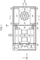
- an air conditioner 400 for a railway vehicle includes an air-conditioning device 100 that air-conditions a passenger compartment of a railway vehicle, and a housing 200 accommodating the air-conditioning device 100.
- the air-conditioning device 100 and the housing 200 are located on the roof of the railway vehicle.
- the air-conditioning device 100 provides two refrigeration cycles. More specifically, the air-conditioning device 100 includes a refrigeration cycle system 110 that provides a first refrigeration cycle and a refrigeration cycle system 120 that provides a second refrigeration cycle.
- the refrigeration cycle system 110 includes a first outdoor heat exchanger 111 serving as a condenser that condenses the refrigerant and a first cooperative device that provides the first refrigeration cycle in cooperation with the first outdoor heat exchanger 111.
- the first cooperative device includes a first expander 112 that expands the refrigerant condensed by the first outdoor heat exchanger 111, a first indoor heat exchanger 113 serving as an evaporator that evaporates the expanded refrigerant, and a first compressor 114 that compresses the evaporated refrigerant to return the refrigerant to the first outdoor heat exchanger 111.
- the refrigeration cycle system 110 also includes a first connection pipe 115 through which the refrigerant flows.
- the first connection pipe 115 connects the first outdoor heat exchanger 111, the first expander 112, the first indoor heat exchanger 113, and the first compressor 114 to form a closed circuit.
- the refrigeration cycle system 120 includes a second outdoor heat exchanger 121 serving as a condenser that condenses the refrigerant and a second cooperative device that provides the second refrigeration cycle in cooperation with the second outdoor heat exchanger 121.
- the second cooperative device includes a second expander 122 that expands the refrigerant condensed by the second outdoor heat exchanger 121, a second indoor heat exchanger 123 serving as an evaporator that evaporates the expanded refrigerant, and a second compressor 124 that compresses the evaporated refrigerant to return the refrigerant to the second outdoor heat exchanger 121.
- the refrigeration cycle system 120 also includes a second connection pipe 125 through which the refrigerant flows.
- the second connection pipe 125 connects the second outdoor heat exchanger 121, the second expander 122, the second indoor heat exchanger 123, and the second compressor 124 to form a closed circuit.
- the air-conditioning device 100 also includes an outdoor blower 130.
- the outdoor blower 130 promotes heat exchange between the first outdoor heat exchanger 111 and air outside the vehicle or outside air and heat exchange between the second outdoor heat exchanger 121 and outside air.
- the air-conditioning device 100 also includes an indoor blower 140.
- the indoor blower 140 promotes heat exchange between the first indoor heat exchanger 113 and air in the passenger compartment and heat exchange between the second indoor heat exchanger 123 and air in the passenger compartment.
- the housing 200 includes a box-shaped base frame 220 having a bottom plate 210 and a top plate 230 covering an upper opening of the base frame 220.
- a part of the top plate 230 is illustrated to indicate the inside of the housing 200.
- a right-handed XYZ orthogonal coordinate system is defined with X-axis parallel to the length direction of the railway vehicle, Y-axis parallel to the width direction of the railway vehicle, and Z-axis parallel to the height direction of the railway vehicle.
- a positive Z-direction corresponds to the upward direction in the height direction.
- the housing 200 also includes partition walls 240 and 250 that partition the interior space defined by the base frame 220 and the top plate 230 into an outdoor-unit chamber S1 serving as a first compartment, an indoor-unit chamber S2 serving as a second compartment, and a compressor chamber S3.
- the outdoor-unit chamber S1, the indoor-unit chamber S2, and the compressor chamber S3 are arranged in X-direction.
- the outdoor-unit chamber S1 accommodates the first outdoor heat exchanger 111, the second outdoor heat exchanger 121, and the outdoor blower 130.
- the indoor-unit chamber S2 accommodates the first expander 112, the first indoor heat exchanger 113, the second expander 122, the second indoor heat exchanger 123, and the indoor blower 140.
- the compressor chamber S3 accommodates the first compressor 114 and the second compressor 124.
- the air conditioner 400 for a railway vehicle is characterized in that the first outdoor heat exchanger 111 and the second outdoor heat exchanger 121 in the outdoor-unit chamber S1 have the same structure.
- the structure of the outdoor-unit chamber S1 is described in detail below.
- FIG. 2A is a cross-sectional view taken along line II-II in FIG. 1 .
- the first outdoor heat exchanger 111 and the second outdoor heat exchanger 121 face each other in Y-direction.
- the first outdoor heat exchanger 111 and the second outdoor heat exchanger 121 are examples of a first heat exchanger and a second heat exchanger facing each other.
- the outdoor blower 130 is located between the first heat exchanger 111 and the second heat exchanger 121.
- the outdoor blower 130 is an example of a blower located between the first heat exchanger and the second heat exchanger.
- first outdoor heat exchanger 111 and the second outdoor heat exchanger 121 are symmetric to each other with respect to an imaginary XZ plane VP extending through the position of the outdoor blower 130.
- the imaginary XZ plane VP is an imaginary plane parallel to X-axis and Z-axis.
- An angle ⁇ between the first outdoor heat exchanger 111 and the bottom plate 210 is equal to an angle ⁇ between the second outdoor heat exchanger 121 and the bottom plate 210.
- the angle ⁇ is greater than or equal to 20 degrees and less than or equal to 70 degrees.
- the housing 200 has first vents 261 connected outside in a portion facing the first outdoor heat exchanger 111.
- the housing 200 has second vents 262 connected outside in a portion facing the second outdoor heat exchanger 121.
- the housing 200 has third vents 263 connected outside in a portion facing the outdoor blower 130.
- the outdoor blower 130 draws outside air into the outdoor-unit chamber S1 through the first vents 261 and the second vents 262 or through the third vents 263, allows the outside air drawn into the outdoor-unit chamber S1 to pass through the first outdoor heat exchanger 111 and the second outdoor heat exchanger 121, and discharges the air outside through the third vents 263 or through the first vents 261 and the second vents 262.
- the outdoor blower 130 draws outside air into the outdoor-unit chamber S1 through the third vents 263 to generate airflow AF in the outdoor-unit chamber S1.
- the airflow AF passes through each of the first outdoor heat exchanger 111 and the second outdoor heat exchanger 121 in the thickness direction and then flows out through the first vents 261 and the second vents 262.
- a comparative example as an example known technique is described below for the issues to be solved with the structure according to the present embodiment.
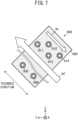
- FIG. 7 illustrates the structure in the comparative example corresponding to the first outdoor heat exchanger 111 in FIG. 2A .
- a first outdoor heat exchanger 900 in the comparative example includes multiple refrigerant pipes 911, 912, 913, and 914, and fins 920 that are thermally connected to the refrigerant pipes 911 to 914.
- the refrigerant pipes 911 to 914 are at different positions in the thickness direction in which airflow AF passes through the first outdoor heat exchanger 900.
- the first outdoor heat exchanger 900 includes an inlet 930 through which the refrigerant to be used for heat exchange by the first outdoor heat exchanger 900 flows in, and an outlet 940 through which the refrigerant used for heat exchange by the first outdoor heat exchanger 900 flows out.
- the inlet 930 and the outlet 940 are at different positions in the thickness direction.
- the multiple refrigerant pipes 911 to 914 are serially interconnected at turns (not illustrated) located at both ends in X-direction.
- the refrigerant thus sequentially passes through the refrigerant pipes 911 to 914 at different positions in the thickness direction. More specifically, the refrigerant sequentially passes through the refrigerant pipes 911, 912, 913, and 914 in this order.
- Arrow AL indicates the direction in which the refrigerant passes through the refrigerant pipes.
- the first outdoor heat exchanger 900 is in an opposite placement that allows the direction indicated by arrow AL to be opposite to the direction of the airflow AF passing through the first outdoor heat exchanger 900.
- a second outdoor heat exchanger (not illustrated) in the comparative example facing the first outdoor heat exchanger 900 is to be in the opposite placement.
- the opposite placement can yield higher heat-exchange efficiency than a parallel placement that allows the direction indicated by arrow AL to be parallel to the direction of the airflow AF.
- first outdoor heat exchanger 900 and the second outdoor heat exchanger are both in the opposite placement, the first outdoor heat exchanger 900 and the second outdoor heat exchanger (not illustrated) are to be mirror symmetric to each other. In other words, the first outdoor heat exchanger 900 and the second outdoor heat exchanger (not illustrated) cannot be congruent.
- the first outdoor heat exchanger 900 and the second outdoor heat exchanger have different specifications to have both the heat exchangers in the opposite placement.
- Such two outdoor heat exchangers with different specifications increase the costs of air conditioners 400 for railway vehicles and increase difficulty in manufacturing the air conditioners 400.
- the first outdoor heat exchanger 900 and the second outdoor heat exchanger may have the same specifications when one the first outdoor heat exchanger 900 or the second outdoor heat exchanger is in the opposite placement and the other in the parallel placement. However, the first outdoor heat exchanger 900 or the second outdoor heat exchanger (not illustrated) in the parallel placement may have lower heat-exchange efficiency.
- the present embodiment is directed to the issues of avoiding lower heat-exchange efficiency that results from the directions of airflow AF and allowing the first outdoor heat exchanger 111 and the second outdoor heat exchanger 121 to have the same specifications.
- the present embodiment directed to the above issues is described below.
- the first outdoor heat exchanger 111 is described below.
- the second outdoor heat exchanger 121 has the same structure as the first outdoor heat exchanger 111.
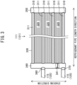
- FIG. 3 is a side view of the first outdoor heat exchanger 111 in the present embodiment, as viewed in the thickness direction in which the airflow AF passes through the first outdoor heat exchanger 111.
- the first outdoor heat exchanger 111 includes a body 330.
- the body 330 includes a stacked structure in which refrigerant pipes 310 and fins 320 are alternately stacked. The refrigerant flows through the refrigerant pipes 310.
- the refrigerant pipes 310 and the fins 320 are stacked in the direction (hereafter referred to as a stacking direction) perpendicular to a length direction (hereafter referred to as a refrigerant pipe length direction) of the refrigerant pipes 310 and to the thickness direction in which the airflow AF illustrated in FIG. 2A passes through the first outdoor heat exchanger 111.
- Each refrigerant pipe 310 internally defines multiple refrigerant flow paths 311.
- the refrigerant flows through the refrigerant flow paths 311.
- the refrigerant flow paths 311 in the refrigerant pipes 310 are arranged in the thickness direction perpendicular to the page of FIG. 3 .
- Each fin 320 is brazed to adjacent ones of the refrigerant pipes 310 in the stacking direction. Each fin 320 is thus thermally connected to the adjacent refrigerant pipes 310 in the stacking direction. More specifically, each fin 320 is a corrugated fin being a metal plate folded in a wave shape.
- the first outdoor heat exchanger 111 includes a first header pipe 340 located at one end of the body 330 in the refrigerant pipe length direction and a second header pipe 350 located at the other end of the body 330 in the refrigerant pipe length direction.
- the first header pipe 340 and the second header pipe 350 extend in the stacking direction.
- the first header pipe 340 connects the refrigerant flow paths 311 in each refrigerant pipe 310 to one another at one end in the refrigerant pipe length direction.
- the second header pipe 350 connects the refrigerant flow paths 311 in each refrigerant pipe 310 to one another at the other end in the refrigerant pipe length direction.
- the refrigerant flow paths 311 arranged in the thickness direction in each refrigerant pipe 310 are thus connected in parallel to one another.
- the first header pipe 340 includes an inlet 360 through which the refrigerant to be used by the first outdoor heat exchanger 111 for heat exchange flows in, and an outlet 370 through which the refrigerant used by the first outdoor heat exchanger 111 for heat exchange flows out.
- the inlet 360 and the outlet 370 face each other in the stacking direction.
- the first connection pipe 115 illustrated also in FIG. 1 is connected to the inlet 360 and the outlet 370. More specifically, the first header pipe 340 allows the refrigerant to flow into and out of the first outdoor heat exchanger 111.
- the first header pipe 340 includes a partition 341 that blocks the refrigerant between the inlet 360 and the outlet 370 in the stacking direction.
- the direction from the partition 341 toward the inlet 360 in the stacking direction is defined as a positive stacking direction, and the direction from the partition 341 toward the outlet 370 in the stacking direction is defined as a negative stacking direction.
- the refrigerant flows from the first header pipe 340 toward the second header pipe 350 through the refrigerant flow paths 311 in the refrigerant pipes 310 located in the positive stacking direction from the partition 341.
- the refrigerant flows from the second header pipe 350 toward the first header pipe 340 through the refrigerant flow paths 311 in the refrigerant pipes 310 located in the negative stacking direction from the partition 341.
- FIG. 4 is a partial cross-sectional view of the first outdoor heat exchanger 111 as viewed in a direction parallel to the thickness direction and the stacking direction.
- Each refrigerant pipe 310 includes the refrigerant flow paths 311 arranged in the thickness direction of the first outdoor heat exchanger 111.
- Each refrigerant pipe 310 thus has, as viewed in a direction parallel to a YZ plane, a cross section that is flat and elongated in one direction, or more specifically, in the thickness direction of the first outdoor heat exchanger 111.
- the refrigerant flow paths 311 arranged in the thickness direction are connected in parallel to one another.
- the refrigerant passes through the refrigerant flow paths 311 non-sequentially.
- the refrigerant passes through the refrigerant flow paths 311 in parallel in the refrigerant pipe length direction.
- the first outdoor heat exchanger 111 thus has heat exchange efficiency that is less dependent on the direction of the airflow AF passing through the first outdoor heat exchanger 111 in the thickness direction.
- the second outdoor heat exchanger 121 and the first outdoor heat exchanger 111 having the same specifications can thus avoid lower heat-exchange efficiency of one of the first heat exchanger 111 or the second heat exchanger 121 that results from the directions of the airflow AF passing through the first heat exchanger 111 and the second heat exchanger 121.
- the second outdoor heat exchanger 121 and the first outdoor heat exchanger 111 are symmetric to each other with respect to a plane.
- the airflow AF passes through the first outdoor heat exchanger 111 from a first end to a second end in the thickness direction
- the airflow AF passes through the second outdoor heat exchanger 121 having the same specifications as the first outdoor heat exchanger 111 from a second end to a first end in the thickness direction.
- the first outdoor heat exchanger 111 and the second outdoor heat exchanger 121 each include the refrigerant flow paths 311 illustrated in FIG. 4 that are connected in parallel to one another.
- the heat exchange efficiency is dependent on the directions of the airflow AF passing through the heat exchangers.
- the first outdoor heat exchanger 111 and the second outdoor heat exchanger 121 having the same specifications can avoid lower heat-exchange efficiency of one of the first heat exchanger 111 or the second heat exchanger 121 that results from the directions of the airflow AF passing through the first heat exchanger 111 and the second heat exchanger 121.
- the first outdoor heat exchanger 111 and the second outdoor heat exchanger 121 having the same specifications herein refer to the first outdoor heat exchanger 111 and the second outdoor heat exchanger 121 having the overall shapes of the flow paths for the refrigerant being congruent.
- the shapes being congruent refers to the shapes being superposable on each other imaginarily.
- the first outdoor heat exchanger 111 and the second outdoor heat exchanger 121 can thus have some structural differences other than in the overall shape of the flow paths for the refrigerant.
- the first outdoor heat exchanger 111 and the second outdoor heat exchanger 121 can have the same specifications.
- the air conditioner 400 for a railway vehicle can be easily manufactured at low costs.
- the relative positions of the first outdoor heat exchanger 111 and the second outdoor heat exchanger 121 are described in detail below.
- the first heat exchanger 111 and the second heat exchanger 121 are each placed with the refrigerant pipe length direction aligned with X-direction.
- the first header pipe 340 of the first heat exchanger 111 and the first header pipe 340 of the second heat exchanger 121 face each other in Y-direction.
- the first header pipe 340 of the first heat exchanger 111 is located at an end of the first heat exchanger 111 nearer the indoor-unit chamber S2 in X-direction.
- the first header pipe 340 of the second heat exchanger 121 is located at an end of the second heat exchanger 121 nearer the indoor-unit chamber S2 in X-direction. More specifically, the first header pipe 340 of the first heat exchanger 111 and the first header pipe 340 of the second heat exchanger 121 face the partition wall 240 partitioning the outdoor-unit chamber S1 and the indoor-unit chamber S2 from each other.
- the first header pipe 340 that allows the refrigerant to flow into and out of the first heat exchanger 111 is located at the end in X-direction nearer the indoor-unit chamber S2. This structure reduces the path length of the first connection pipe 115 in the refrigeration cycle system 110.
- the first header pipe 340 that allows the refrigerant to flow into and out of the second heat exchanger 121 is located at the end in X-direction nearer the indoor-unit chamber S2. This structure reduces the path length of the second connection pipe 125 in the refrigeration cycle system 120.
- FIG. 2A also illustrates the first header pipes 340 of the first heat exchanger 111 and the second heat exchanger 121.
- the inlet 360 in the first outdoor heat exchanger 111 and the inlet 360 in the second outdoor heat exchanger 121 face each other in Y-direction.
- the outlet 370 in the first outdoor heat exchanger 111 and the outlet 370 in the second outdoor heat exchanger 121 face each other in Y-direction.
- the first connection pipe 115 and the second connection pipe 125 illustrated in FIG. 1 are thus installed symmetrically with respect to the imaginary XZ plane VP. This simplifies the installation pattern of the first connection pipe 115 and the second connection pipe 125 and facilitates manufacturing of the air conditioner 400 for a railway vehicle.
- an outdoor blower 130 in Modification 1 draws outside air into the outdoor-unit chamber S1 through the first vents 261 and the second vents 262 to generate airflow AF in the outdoor-unit chamber S1.
- the airflow AF passes through the first outdoor heat exchanger 111 and the second outdoor heat exchanger 121 in the thickness direction and then flows out through the third vents 263.
- the directions of the airflow AF in FIG. 2B is opposite to the directions of the airflow AF in FIG. 2A .
- the directions of the airflow AF passing through the first outdoor heat exchanger 111 and the second outdoor heat exchanger 121 in FIG. 2B is thus also opposite to the directions of the airflow AF in FIG. 2A .
- the first outdoor heat exchanger 111 and the second outdoor heat exchanger 121 with the above structure have the heat exchange efficiency that is less dependent on the directions of the airflow AF passing through the heat exchangers.
- the structure for generating the airflow AF in FIG. 2A (hereafter referred to as a downward blowing structure) and the structure for generating the airflow AF in FIG. 2B (hereafter referred to as an upward blowing structure) both including the same first outdoor heat exchanger 111 and the same second outdoor heat exchanger 121 can have substantially the same heat exchange efficiency.
- the first outdoor heat exchanger 111 and the second outdoor heat exchanger 121 are usable for both the downward blowing structure and the upward blowing structure. This can facilitate control of the production of the components of the air conditioner 400 for a railway vehicle. This advantageous effect is particularly produced by the air conditioner 400 for a railway vehicle with the upward blowing structure or the downward blowing structure.
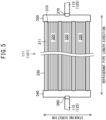
- a second header pipe 350 in each of the first outdoor heat exchanger 111 and the second outdoor heat exchanger 121 in Modification 2 has an outlet 370.
- the inlet 360 is located in the first header pipe 340.
- the first connection pipe 115 and the second connection pipe 125 illustrated in FIG. 1 are longer in the structure in Modification 2 than in the structure in the embodiment, the refrigerant can flow at a constant rate through the multiple refrigerant pipes 310 arranged in the stacking direction.
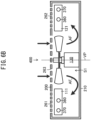
- FIGS. 6A and 6B illustrate structures in the outdoor-unit chamber S1 in Modifications 3 and 4.
- each of the first outdoor heat exchanger 111 and the second outdoor heat exchanger 121 is at an angle (hereafter referred to as an installation angle) ⁇ of 90 degrees with respect to the bottom plate 210.
- the installation angle is 0 degrees, or more specifically, each of the first outdoor heat exchanger 111 and the second outdoor heat exchanger 121 is parallel to the bottom plate 210.
- the installation angle is not limited to 0 or 90 degrees, and may be greater than or equal to 0 degrees and less than or equal to 90 degrees.
- the indoor-unit chamber S2 has the same layout as the outdoor-unit chamber S1. More specifically, the first indoor heat exchanger 113 and the second indoor heat exchanger 123 serving as evaporators face each other, similarly to the first outdoor heat exchanger 111 and the second outdoor heat exchanger 121 serving as condensers.
- the indoor blower 140 is located between the first indoor heat exchanger 113 and the second indoor heat exchanger 123.
- the indoor blower 140 generates airflow passing through the first indoor heat exchanger 113 and the second indoor heat exchanger 123 in the thickness direction in the indoor-unit chamber S2.
- the structures illustrated in FIGS. 3 to 5 is applicable to the first indoor heat exchanger 113 and the second indoor heat exchanger 123 serving as evaporators.
- Water hereafter referred to as condensate
- the refrigerant pipes 310 are flat and elongated in the thickness direction. The condensate may thus accumulate on the refrigerant pipes 310.
- the structures illustrated in FIGS. 3 to 5 is thus applicable to condensers rather than evaporators.
Landscapes
- Engineering & Computer Science (AREA)
- Mechanical Engineering (AREA)
- Physics & Mathematics (AREA)
- Thermal Sciences (AREA)
- Other Air-Conditioning Systems (AREA)
- Air-Conditioning For Vehicles (AREA)
Abstract
Description
- The present disclosure relates to an air conditioner for a railway vehicle.
- A passenger compartment of a railway vehicle is air-conditioned with a refrigeration cycle, similarly to a passenger compartment of an automobile. Although a passenger compartment of an automobile can be air-conditioned with a single refrigeration cycle system, a passenger compartment of a railway vehicle that is much larger than a passenger compartment of an automobile uses at least two refrigeration cycle systems for air conditioning. A passenger compartment of a railway vehicle is thus air-conditioned with an air conditioner for a railway vehicle including at least a pair of heat exchangers.
-
Patent Literature 1 describes a layout of a pair of heat exchangers in an air conditioner for a railway vehicle. As described inPatent Literature 1, the pair of heat exchangers face each other across a blower. The blower generates airflow passing through each heat exchanger in the thickness direction of the heat exchanger. - Patent Literature 1: Unexamined
Japanese Patent Application Publication No. 2007-327653 - Each heat exchanger in
Patent Literature 1 includes multiple refrigerant pipes inside at different positions in the thickness direction of the heat exchanger. The refrigerant pipes are serially connected. In each heat exchanger inPatent Literature 1, the refrigerant thus sequentially passes through the refrigerant pipes that are at different positions in the thickness direction. More specifically, the refrigerant passes through the refrigerant pipes from one end to the other end in the thickness direction. - Each heat exchanger in
Patent Literature 1 is thus placed to have either the refrigerant passing through the refrigerant pipes in the direction opposite to the airflow passing through the heat exchanger (hereafter referred to as being in an opposite placement) or the refrigerant passing through the refrigerant pipes in the direction parallel to the airflow passing through the heat exchanger (hereafter referred to as being in a parallel placement). - The opposite placement yields higher heat-exchange efficiency than the parallel placement. Although the pair of heat exchangers may both be in the opposite placement, the heat exchangers in the opposite placement are mirror symmetric across a blower and cannot have the same structure. In other words, the pair of heat exchangers have different specifications.
- When the pair of heat exchangers across the blower have the same specifications, one of the heat exchangers is in the opposite placement and the other in the parallel placement. The other heat exchanger may thus have lower heat-exchange efficiency.
- Although the pair of heat exchangers in
Patent Literature 1 are to be in the opposite placement and have different specifications to avoid lower heat-exchange efficiency as described above, such two heat exchangers with different specifications can increase the costs of air conditioners for railway vehicles and increase difficulty in manufacturing the air conditioners. The above issues, uncommon to the air conditioner for an automobile that includes a single refrigeration cycle, occur to the air conditioner for a railway vehicle that includes a pair of heat exchangers facing each other. - An objective of the present disclosure is to provide an air conditioner for a railway vehicle that is easily manufactured at low costs.
- An air conditioner for a railway vehicle according to an aspect of the present disclosure includes a first heat exchanger and a second heat exchanger facing each other, and a blower located between the first heat exchanger and the second heat exchanger and configured to generate airflow passing through the first heat exchanger and the second heat exchanger. Each of the first heat exchanger and the second heat exchanger includes a body including a stacked structure in which refrigerant pipes and fins are alternately stacked in a direction perpendicular to a thickness direction in which the airflow passes through the first heat exchanger or the second heat exchanger. Each of the refrigerant pipes internally defines a plurality of refrigerant flow paths. The plurality of refrigerant flow paths in each of the refrigerant pipes are arranged in the thickness direction. Each of the first heat exchanger and the second heat exchanger includes a first header pipe located at a first end of the body in a length direction of the refrigerant pipes. The first header pipe connects the plurality of refrigerant flow paths in each of the refrigerant pipes to one another at the first end. Each of the first heat exchanger and the second heat exchanger includes a second header pipe located at a second end of the body in the length direction of the refrigerant pipes. The second header pipe connects the plurality of refrigerant flow paths in each of the refrigerant pipes to one another at the second end.
- In the above structure, each of the first heat exchanger and the second heat exchanger includes the refrigerant pipes each defining the plurality of refrigerant flow paths that are connected to one another at both ends in the length direction of the refrigerant pipes. In other words, the refrigerant flow paths in each refrigerant pipe arranged in the thickness direction are connected in parallel. The refrigerant thus passes through the plurality of refrigerant flow paths in parallel, instead of passing through the paths in sequence.
- The first heat exchanger is less likely to have a change in the heat-exchange efficiency between when placed to allow airflow from a first end to a second end in the thickness direction of the first heat exchanger and when placed to allow airflow from the second end to the first end in the thickness direction of the first heat exchanger. Similarly, the second heat exchanger is less likely to have a change in the heat-exchange efficiency between when placed to allow airflow from a first end to a second end in the thickness direction of the second heat exchanger and when placed to allow airflow from the second end to the first end in the thickness direction of the second heat exchanger.
- The first heat exchanger and the second heat exchanger having the same specifications can avoid lower heat-exchange efficiency of one of the first heat exchanger or the second heat exchanger that results from the directions of the airflow passing through the first heat exchanger and the second heat exchanger. The air conditioner for a railway vehicle including the first heat exchanger and the second heat exchanger having the same specifications can be easily manufactured at low costs.
-
-
FIG. 1 is a schematic diagram of an air conditioner for a railway vehicle according to an embodiment; -
FIG. 2A is a cross-sectional view of an outdoor-unit chamber in the embodiment, as viewed in the width direction of the railway vehicle; -
FIG. 2B is a cross-sectional view of an outdoor-unit chamber inModification 1, as viewed in the width direction of the railway vehicle; -
FIG. 3 is a side view of a first outdoor heat exchanger in the embodiment, as viewed in the thickness direction; -
FIG. 4 is a partial cross-sectional view of the first outdoor heat exchanger in the embodiment, as viewed in the length direction of refrigerant pipes; -
FIG. 5 is a side view of a first outdoor heat exchanger inModification 2, as viewed in the thickness direction; -
FIG. 6A is a cross-sectional view of an outdoor-unit chamber in Modification 3, as viewed in the width direction of the railway vehicle; -
FIG. 6B is a cross-sectional view of an outdoor-unit chamber in Modification 4, as viewed in the width direction of the railway vehicle; and -
FIG. 7 is a schematic cross-sectional view of a first outdoor heat exchanger in a comparative example. - An air conditioner for a railway vehicle according to an embodiment is described below with reference to the drawings. In the drawings, the same reference signs denote the same or corresponding components.
- As illustrated in
FIG. 1 , anair conditioner 400 for a railway vehicle according to the present embodiment includes an air-conditioning device 100 that air-conditions a passenger compartment of a railway vehicle, and ahousing 200 accommodating the air-conditioning device 100. The air-conditioning device 100 and thehousing 200 are located on the roof of the railway vehicle. - The air-
conditioning device 100 provides two refrigeration cycles. More specifically, the air-conditioning device 100 includes arefrigeration cycle system 110 that provides a first refrigeration cycle and arefrigeration cycle system 120 that provides a second refrigeration cycle. - The
refrigeration cycle system 110 includes a firstoutdoor heat exchanger 111 serving as a condenser that condenses the refrigerant and a first cooperative device that provides the first refrigeration cycle in cooperation with the firstoutdoor heat exchanger 111. The first cooperative device includes afirst expander 112 that expands the refrigerant condensed by the firstoutdoor heat exchanger 111, a firstindoor heat exchanger 113 serving as an evaporator that evaporates the expanded refrigerant, and afirst compressor 114 that compresses the evaporated refrigerant to return the refrigerant to the firstoutdoor heat exchanger 111. - The
refrigeration cycle system 110 also includes afirst connection pipe 115 through which the refrigerant flows. Thefirst connection pipe 115 connects the firstoutdoor heat exchanger 111, thefirst expander 112, the firstindoor heat exchanger 113, and thefirst compressor 114 to form a closed circuit. - Similarly, the
refrigeration cycle system 120 includes a secondoutdoor heat exchanger 121 serving as a condenser that condenses the refrigerant and a second cooperative device that provides the second refrigeration cycle in cooperation with the secondoutdoor heat exchanger 121. The second cooperative device includes asecond expander 122 that expands the refrigerant condensed by the secondoutdoor heat exchanger 121, a secondindoor heat exchanger 123 serving as an evaporator that evaporates the expanded refrigerant, and asecond compressor 124 that compresses the evaporated refrigerant to return the refrigerant to the secondoutdoor heat exchanger 121. - The
refrigeration cycle system 120 also includes asecond connection pipe 125 through which the refrigerant flows. Thesecond connection pipe 125 connects the secondoutdoor heat exchanger 121, thesecond expander 122, the secondindoor heat exchanger 123, and thesecond compressor 124 to form a closed circuit. - The air-
conditioning device 100 also includes anoutdoor blower 130. Theoutdoor blower 130 promotes heat exchange between the firstoutdoor heat exchanger 111 and air outside the vehicle or outside air and heat exchange between the secondoutdoor heat exchanger 121 and outside air. The air-conditioning device 100 also includes anindoor blower 140. Theindoor blower 140 promotes heat exchange between the firstindoor heat exchanger 113 and air in the passenger compartment and heat exchange between the secondindoor heat exchanger 123 and air in the passenger compartment. - The
housing 200 includes a box-shapedbase frame 220 having abottom plate 210 and atop plate 230 covering an upper opening of thebase frame 220. InFIG. 1 , a part of thetop plate 230 is illustrated to indicate the inside of thehousing 200. - For ease of explanation, a right-handed XYZ orthogonal coordinate system is defined with X-axis parallel to the length direction of the railway vehicle, Y-axis parallel to the width direction of the railway vehicle, and Z-axis parallel to the height direction of the railway vehicle. A positive Z-direction corresponds to the upward direction in the height direction.
- The
housing 200 also includespartition walls base frame 220 and thetop plate 230 into an outdoor-unit chamber S1 serving as a first compartment, an indoor-unit chamber S2 serving as a second compartment, and a compressor chamber S3. The outdoor-unit chamber S1, the indoor-unit chamber S2, and the compressor chamber S3 are arranged in X-direction. - The outdoor-unit chamber S1 accommodates the first
outdoor heat exchanger 111, the secondoutdoor heat exchanger 121, and theoutdoor blower 130. The indoor-unit chamber S2 accommodates thefirst expander 112, the firstindoor heat exchanger 113, thesecond expander 122, the secondindoor heat exchanger 123, and theindoor blower 140. The compressor chamber S3 accommodates thefirst compressor 114 and thesecond compressor 124. - The
air conditioner 400 for a railway vehicle according to the present embodiment is characterized in that the firstoutdoor heat exchanger 111 and the secondoutdoor heat exchanger 121 in the outdoor-unit chamber S1 have the same structure. The structure of the outdoor-unit chamber S1 is described in detail below. -
FIG. 2A is a cross-sectional view taken along line II-II inFIG. 1 . As illustrated inFIG. 2A , the firstoutdoor heat exchanger 111 and the secondoutdoor heat exchanger 121 face each other in Y-direction. The firstoutdoor heat exchanger 111 and the secondoutdoor heat exchanger 121 are examples of a first heat exchanger and a second heat exchanger facing each other. - The
outdoor blower 130 is located between thefirst heat exchanger 111 and thesecond heat exchanger 121. Theoutdoor blower 130 is an example of a blower located between the first heat exchanger and the second heat exchanger. - More specifically, the first
outdoor heat exchanger 111 and the secondoutdoor heat exchanger 121 are symmetric to each other with respect to an imaginary XZ plane VP extending through the position of theoutdoor blower 130. The imaginary XZ plane VP is an imaginary plane parallel to X-axis and Z-axis. - An angle θ between the first
outdoor heat exchanger 111 and thebottom plate 210 is equal to an angle θ between the secondoutdoor heat exchanger 121 and thebottom plate 210. In the present embodiment, the angle θ is greater than or equal to 20 degrees and less than or equal to 70 degrees. - The
housing 200 hasfirst vents 261 connected outside in a portion facing the firstoutdoor heat exchanger 111. Thehousing 200 hassecond vents 262 connected outside in a portion facing the secondoutdoor heat exchanger 121. Thehousing 200 hasthird vents 263 connected outside in a portion facing theoutdoor blower 130. - The
outdoor blower 130 draws outside air into the outdoor-unit chamber S1 through thefirst vents 261 and thesecond vents 262 or through thethird vents 263, allows the outside air drawn into the outdoor-unit chamber S1 to pass through the firstoutdoor heat exchanger 111 and the secondoutdoor heat exchanger 121, and discharges the air outside through thethird vents 263 or through thefirst vents 261 and the second vents 262. - More specifically, the
outdoor blower 130 draws outside air into the outdoor-unit chamber S1 through thethird vents 263 to generate airflow AF in the outdoor-unit chamber S1. The airflow AF passes through each of the firstoutdoor heat exchanger 111 and the secondoutdoor heat exchanger 121 in the thickness direction and then flows out through thefirst vents 261 and the second vents 262. - A comparative example as an example known technique is described below for the issues to be solved with the structure according to the present embodiment.
-
FIG. 7 illustrates the structure in the comparative example corresponding to the firstoutdoor heat exchanger 111 inFIG. 2A . A firstoutdoor heat exchanger 900 in the comparative example includes multiplerefrigerant pipes fins 920 that are thermally connected to therefrigerant pipes 911 to 914. Therefrigerant pipes 911 to 914 are at different positions in the thickness direction in which airflow AF passes through the firstoutdoor heat exchanger 900. - The first
outdoor heat exchanger 900 includes aninlet 930 through which the refrigerant to be used for heat exchange by the firstoutdoor heat exchanger 900 flows in, and anoutlet 940 through which the refrigerant used for heat exchange by the firstoutdoor heat exchanger 900 flows out. Theinlet 930 and theoutlet 940 are at different positions in the thickness direction. - The multiple
refrigerant pipes 911 to 914 are serially interconnected at turns (not illustrated) located at both ends in X-direction. The refrigerant thus sequentially passes through therefrigerant pipes 911 to 914 at different positions in the thickness direction. More specifically, the refrigerant sequentially passes through therefrigerant pipes - The first
outdoor heat exchanger 900 is in an opposite placement that allows the direction indicated by arrow AL to be opposite to the direction of the airflow AF passing through the firstoutdoor heat exchanger 900. Similarly, a second outdoor heat exchanger (not illustrated) in the comparative example facing the firstoutdoor heat exchanger 900 is to be in the opposite placement. The opposite placement can yield higher heat-exchange efficiency than a parallel placement that allows the direction indicated by arrow AL to be parallel to the direction of the airflow AF. - When the first
outdoor heat exchanger 900 and the second outdoor heat exchanger (not illustrated) are both in the opposite placement, the firstoutdoor heat exchanger 900 and the second outdoor heat exchanger (not illustrated) are to be mirror symmetric to each other. In other words, the firstoutdoor heat exchanger 900 and the second outdoor heat exchanger (not illustrated) cannot be congruent. - More specifically, with known techniques, the first
outdoor heat exchanger 900 and the second outdoor heat exchanger (not illustrated) have different specifications to have both the heat exchangers in the opposite placement. Such two outdoor heat exchangers with different specifications increase the costs ofair conditioners 400 for railway vehicles and increase difficulty in manufacturing theair conditioners 400. - The first
outdoor heat exchanger 900 and the second outdoor heat exchanger (not illustrated) may have the same specifications when one the firstoutdoor heat exchanger 900 or the second outdoor heat exchanger is in the opposite placement and the other in the parallel placement. However, the firstoutdoor heat exchanger 900 or the second outdoor heat exchanger (not illustrated) in the parallel placement may have lower heat-exchange efficiency. - The present embodiment is directed to the issues of avoiding lower heat-exchange efficiency that results from the directions of airflow AF and allowing the first
outdoor heat exchanger 111 and the secondoutdoor heat exchanger 121 to have the same specifications. - The present embodiment directed to the above issues is described below. The first
outdoor heat exchanger 111 is described below. The secondoutdoor heat exchanger 121 has the same structure as the firstoutdoor heat exchanger 111. -
FIG. 3 is a side view of the firstoutdoor heat exchanger 111 in the present embodiment, as viewed in the thickness direction in which the airflow AF passes through the firstoutdoor heat exchanger 111. As illustrated inFIG. 3 , the firstoutdoor heat exchanger 111 includes abody 330. Thebody 330 includes a stacked structure in whichrefrigerant pipes 310 andfins 320 are alternately stacked. The refrigerant flows through therefrigerant pipes 310. - In the
body 330, therefrigerant pipes 310 and thefins 320 are stacked in the direction (hereafter referred to as a stacking direction) perpendicular to a length direction (hereafter referred to as a refrigerant pipe length direction) of therefrigerant pipes 310 and to the thickness direction in which the airflow AF illustrated inFIG. 2A passes through the firstoutdoor heat exchanger 111. - Each
refrigerant pipe 310 internally defines multiplerefrigerant flow paths 311. The refrigerant flows through therefrigerant flow paths 311. Therefrigerant flow paths 311 in therefrigerant pipes 310 are arranged in the thickness direction perpendicular to the page ofFIG. 3 . - Each
fin 320 is brazed to adjacent ones of therefrigerant pipes 310 in the stacking direction. Eachfin 320 is thus thermally connected to the adjacentrefrigerant pipes 310 in the stacking direction. More specifically, eachfin 320 is a corrugated fin being a metal plate folded in a wave shape. - The first
outdoor heat exchanger 111 includes afirst header pipe 340 located at one end of thebody 330 in the refrigerant pipe length direction and asecond header pipe 350 located at the other end of thebody 330 in the refrigerant pipe length direction. Thefirst header pipe 340 and thesecond header pipe 350 extend in the stacking direction. - The
first header pipe 340 connects therefrigerant flow paths 311 in eachrefrigerant pipe 310 to one another at one end in the refrigerant pipe length direction. Thesecond header pipe 350 connects therefrigerant flow paths 311 in eachrefrigerant pipe 310 to one another at the other end in the refrigerant pipe length direction. Therefrigerant flow paths 311 arranged in the thickness direction in eachrefrigerant pipe 310 are thus connected in parallel to one another. - The
first header pipe 340 includes aninlet 360 through which the refrigerant to be used by the firstoutdoor heat exchanger 111 for heat exchange flows in, and anoutlet 370 through which the refrigerant used by the firstoutdoor heat exchanger 111 for heat exchange flows out. - The
inlet 360 and theoutlet 370 face each other in the stacking direction. Thefirst connection pipe 115 illustrated also inFIG. 1 is connected to theinlet 360 and theoutlet 370. More specifically, thefirst header pipe 340 allows the refrigerant to flow into and out of the firstoutdoor heat exchanger 111. - The
first header pipe 340 includes apartition 341 that blocks the refrigerant between theinlet 360 and theoutlet 370 in the stacking direction. The direction from thepartition 341 toward theinlet 360 in the stacking direction is defined as a positive stacking direction, and the direction from thepartition 341 toward theoutlet 370 in the stacking direction is defined as a negative stacking direction. - The refrigerant flows from the
first header pipe 340 toward thesecond header pipe 350 through therefrigerant flow paths 311 in therefrigerant pipes 310 located in the positive stacking direction from thepartition 341. The refrigerant flows from thesecond header pipe 350 toward thefirst header pipe 340 through therefrigerant flow paths 311 in therefrigerant pipes 310 located in the negative stacking direction from thepartition 341. -
FIG. 4 is a partial cross-sectional view of the firstoutdoor heat exchanger 111 as viewed in a direction parallel to the thickness direction and the stacking direction. Eachrefrigerant pipe 310 includes therefrigerant flow paths 311 arranged in the thickness direction of the firstoutdoor heat exchanger 111. Eachrefrigerant pipe 310 thus has, as viewed in a direction parallel to a YZ plane, a cross section that is flat and elongated in one direction, or more specifically, in the thickness direction of the firstoutdoor heat exchanger 111. As described above, therefrigerant flow paths 311 arranged in the thickness direction are connected in parallel to one another. Thus, unlike in the structure in the comparative example, the refrigerant passes through therefrigerant flow paths 311 non-sequentially. The refrigerant passes through therefrigerant flow paths 311 in parallel in the refrigerant pipe length direction. - The first
outdoor heat exchanger 111 thus has heat exchange efficiency that is less dependent on the direction of the airflow AF passing through the firstoutdoor heat exchanger 111 in the thickness direction. The secondoutdoor heat exchanger 121 and the firstoutdoor heat exchanger 111 having the same specifications can thus avoid lower heat-exchange efficiency of one of thefirst heat exchanger 111 or thesecond heat exchanger 121 that results from the directions of the airflow AF passing through thefirst heat exchanger 111 and thesecond heat exchanger 121. - The above structure is described more specifically with reference to
FIG. 2A . As described above, the secondoutdoor heat exchanger 121 and the firstoutdoor heat exchanger 111 are symmetric to each other with respect to a plane. When the airflow AF passes through the firstoutdoor heat exchanger 111 from a first end to a second end in the thickness direction, the airflow AF passes through the secondoutdoor heat exchanger 121 having the same specifications as the firstoutdoor heat exchanger 111 from a second end to a first end in the thickness direction. - As described above, the first
outdoor heat exchanger 111 and the secondoutdoor heat exchanger 121 each include therefrigerant flow paths 311 illustrated inFIG. 4 that are connected in parallel to one another. Thus, the heat exchange efficiency is dependent on the directions of the airflow AF passing through the heat exchangers. The firstoutdoor heat exchanger 111 and the secondoutdoor heat exchanger 121 having the same specifications can avoid lower heat-exchange efficiency of one of thefirst heat exchanger 111 or thesecond heat exchanger 121 that results from the directions of the airflow AF passing through thefirst heat exchanger 111 and thesecond heat exchanger 121. - The first
outdoor heat exchanger 111 and the secondoutdoor heat exchanger 121 having the same specifications herein refer to the firstoutdoor heat exchanger 111 and the secondoutdoor heat exchanger 121 having the overall shapes of the flow paths for the refrigerant being congruent. The shapes being congruent refers to the shapes being superposable on each other imaginarily. The firstoutdoor heat exchanger 111 and the secondoutdoor heat exchanger 121 can thus have some structural differences other than in the overall shape of the flow paths for the refrigerant. - As described above, the first
outdoor heat exchanger 111 and the secondoutdoor heat exchanger 121 can have the same specifications. Thus, theair conditioner 400 for a railway vehicle can be easily manufactured at low costs. - The relative positions of the first
outdoor heat exchanger 111 and the secondoutdoor heat exchanger 121 are described in detail below. - As illustrated in
FIG. 1 , thefirst heat exchanger 111 and thesecond heat exchanger 121 are each placed with the refrigerant pipe length direction aligned with X-direction. Thefirst header pipe 340 of thefirst heat exchanger 111 and thefirst header pipe 340 of thesecond heat exchanger 121 face each other in Y-direction. - The
first header pipe 340 of thefirst heat exchanger 111 is located at an end of thefirst heat exchanger 111 nearer the indoor-unit chamber S2 in X-direction. Similarly, thefirst header pipe 340 of thesecond heat exchanger 121 is located at an end of thesecond heat exchanger 121 nearer the indoor-unit chamber S2 in X-direction. More specifically, thefirst header pipe 340 of thefirst heat exchanger 111 and thefirst header pipe 340 of thesecond heat exchanger 121 face thepartition wall 240 partitioning the outdoor-unit chamber S1 and the indoor-unit chamber S2 from each other. - The
first header pipe 340 that allows the refrigerant to flow into and out of thefirst heat exchanger 111 is located at the end in X-direction nearer the indoor-unit chamber S2. This structure reduces the path length of thefirst connection pipe 115 in therefrigeration cycle system 110. - The
first header pipe 340 that allows the refrigerant to flow into and out of thesecond heat exchanger 121 is located at the end in X-direction nearer the indoor-unit chamber S2. This structure reduces the path length of thesecond connection pipe 125 in therefrigeration cycle system 120. -
FIG. 2A also illustrates thefirst header pipes 340 of thefirst heat exchanger 111 and thesecond heat exchanger 121. Theinlet 360 in the firstoutdoor heat exchanger 111 and theinlet 360 in the secondoutdoor heat exchanger 121 face each other in Y-direction. Theoutlet 370 in the firstoutdoor heat exchanger 111 and theoutlet 370 in the secondoutdoor heat exchanger 121 face each other in Y-direction. - The
first connection pipe 115 and thesecond connection pipe 125 illustrated inFIG. 1 are thus installed symmetrically with respect to the imaginary XZ plane VP. This simplifies the installation pattern of thefirst connection pipe 115 and thesecond connection pipe 125 and facilitates manufacturing of theair conditioner 400 for a railway vehicle. - The embodiment described above may be modified as described below.
- As illustrated in
FIG. 2B , anoutdoor blower 130 inModification 1 draws outside air into the outdoor-unit chamber S1 through thefirst vents 261 and thesecond vents 262 to generate airflow AF in the outdoor-unit chamber S1. The airflow AF passes through the firstoutdoor heat exchanger 111 and the secondoutdoor heat exchanger 121 in the thickness direction and then flows out through the third vents 263. - In other words, the directions of the airflow AF in
FIG. 2B is opposite to the directions of the airflow AF inFIG. 2A . The directions of the airflow AF passing through the firstoutdoor heat exchanger 111 and the secondoutdoor heat exchanger 121 inFIG. 2B is thus also opposite to the directions of the airflow AF inFIG. 2A . However, as described above, the firstoutdoor heat exchanger 111 and the secondoutdoor heat exchanger 121 with the above structure have the heat exchange efficiency that is less dependent on the directions of the airflow AF passing through the heat exchangers. - Thus, the structure for generating the airflow AF in
FIG. 2A (hereafter referred to as a downward blowing structure) and the structure for generating the airflow AF inFIG. 2B (hereafter referred to as an upward blowing structure) both including the same firstoutdoor heat exchanger 111 and the same secondoutdoor heat exchanger 121 can have substantially the same heat exchange efficiency. More specifically, the firstoutdoor heat exchanger 111 and the secondoutdoor heat exchanger 121 are usable for both the downward blowing structure and the upward blowing structure. This can facilitate control of the production of the components of theair conditioner 400 for a railway vehicle. This advantageous effect is particularly produced by theair conditioner 400 for a railway vehicle with the upward blowing structure or the downward blowing structure. - As illustrated in
FIG. 5 , asecond header pipe 350 in each of the firstoutdoor heat exchanger 111 and the secondoutdoor heat exchanger 121 inModification 2 has anoutlet 370. As in the embodiment illustrated inFIG. 3 , theinlet 360 is located in thefirst header pipe 340. Although thefirst connection pipe 115 and thesecond connection pipe 125 illustrated inFIG. 1 are longer in the structure inModification 2 than in the structure in the embodiment, the refrigerant can flow at a constant rate through the multiplerefrigerant pipes 310 arranged in the stacking direction. -
FIGS. 6A and6B illustrate structures in the outdoor-unit chamber S1 in Modifications 3 and 4. InFIG. 6A , each of the firstoutdoor heat exchanger 111 and the secondoutdoor heat exchanger 121 is at an angle (hereafter referred to as an installation angle) θ of 90 degrees with respect to thebottom plate 210. InFIG. 6B , the installation angle is 0 degrees, or more specifically, each of the firstoutdoor heat exchanger 111 and the secondoutdoor heat exchanger 121 is parallel to thebottom plate 210. The installation angle is not limited to 0 or 90 degrees, and may be greater than or equal to 0 degrees and less than or equal to 90 degrees. - As illustrated in
FIG. 1 , the indoor-unit chamber S2 has the same layout as the outdoor-unit chamber S1. More specifically, the firstindoor heat exchanger 113 and the secondindoor heat exchanger 123 serving as evaporators face each other, similarly to the firstoutdoor heat exchanger 111 and the secondoutdoor heat exchanger 121 serving as condensers. - The
indoor blower 140 is located between the firstindoor heat exchanger 113 and the secondindoor heat exchanger 123. Theindoor blower 140 generates airflow passing through the firstindoor heat exchanger 113 and the secondindoor heat exchanger 123 in the thickness direction in the indoor-unit chamber S2. - The structures illustrated in
FIGS. 3 to 5 is applicable to the firstindoor heat exchanger 113 and the secondindoor heat exchanger 123 serving as evaporators. Water (hereafter referred to as condensate) caused by condensation adheres to the evaporators. Unlike the knownrefrigerant pipes 911 to 914, therefrigerant pipes 310 are flat and elongated in the thickness direction. The condensate may thus accumulate on therefrigerant pipes 310. The structures illustrated inFIGS. 3 to 5 is thus applicable to condensers rather than evaporators. - The foregoing describes some example embodiments for explanatory purposes. Although the foregoing discussion has presented specific embodiments, persons skilled in the art will recognize that changes may be made in form and detail without departing from the broader spirit and scope of the invention. Accordingly, the specification and drawings are to be regarded in an illustrative rather than a restrictive sense. This detailed description, therefore, is not to be taken in a limiting sense, and the scope of the invention is defined only by the included claims, along with the full range of equivalents to which such claims are entitled.
-
- 100
- Air-conditioning device
- 110, 120
- Refrigeration cycle system
- 111
- First outdoor heat exchanger (first heat exchanger, condenser)
- 112
- First expander
- 113
- First indoor heat exchanger
- 114
- First compressor
- 115
- First connection pipe
- 121
- Second outdoor heat exchanger (second heat exchanger, condenser)
- 122
- Second expander
- 123
- Second indoor heat exchanger
- 124
- Second compressor
- 125
- Second connection pipe
- 130
- Outdoor blower (blower)
- 140
- Indoor blower
- 200
- Housing
- 210
- Bottom plate
- 220
- Base frame
- 230
- Top plate
- 240,
- 250 Partition wall
- 261
- First vent
- 262
- Second vent
- 263
- Third vent
- 310
- Refrigerant pipe
- 311
- Refrigerant flow path
- 320
- Fin
- 330
- Body
- 340
- First header pipe
- 341
- Partition
- 350
- Second header pipe
- 360
- Inlet
- 370
- Outlet
- 400
- Air conditioner for railway vehicle
- 900
- First outdoor heat exchanger
- 911, 912, 913, 914
- Refrigerant pipe
- 920
- Fin
- 930
- Inlet
- 940
- Outlet
- AF
- Airflow
- AL
- Arrow
- S1
- Outdoor-unit chamber (first compartment)
- S2
- Indoor-unit chamber (second compartment)
- S3
- Compressor chamber
- VP
- Imaginary XZ plane
Claims (7)
- An air conditioner for a railway vehicle, the air conditioner comprising:a first heat exchanger and a second heat exchanger facing each other; anda blower located between the first heat exchanger and the second heat exchanger and configured to generate airflow passing through the first heat exchanger and the second heat exchanger,each of the first heat exchanger and the second heat exchanger includinga body including a stacked structure in which refrigerant pipes and fins are alternately stacked in a direction perpendicular to a thickness direction in which the airflow passes through the first heat exchanger or the second heat exchanger, each of the refrigerant pipes internally defining a plurality of refrigerant flow paths, the plurality of refrigerant flow paths in each of the refrigerant pipes being arranged in the thickness direction,a first header pipe located at a first end of the body in a length direction of the refrigerant pipes, the first header pipe connecting the plurality of refrigerant flow paths in each of the refrigerant pipes to one another at the first end, anda second header pipe located at a second end of the body in the length direction of the refrigerant pipes, the second header pipe connecting the plurality of refrigerant flow paths in each of the refrigerant pipes to one another at the second end.
- The air conditioner according to claim 1, whereinthe first header pipe of the first heat exchanger has an inlet through which a refrigerant to be used by the first heat exchanger for heat exchange flows in, and an outlet through which the refrigerant used by the first heat exchanger for the heat exchange flows out,the first header pipe of the second heat exchanger has an inlet through which a refrigerant to be used by the second heat exchanger for heat exchange flows in, and an outlet through which the refrigerant used by the second heat exchanger for the heat exchange flows out, andthe first header pipe of the first heat exchanger and the first header pipe of the second heat exchanger face each other.
- The air conditioner according to claim 2, further comprising:a housing defining a first compartment and a second compartment, the first compartment accommodating the first heat exchanger and the second heat exchanger, the second compartment accommodating a first cooperative device and a second cooperative device, the first cooperative device providing a first refrigeration cycle in cooperation with the first heat exchanger, the second cooperative device providing a second refrigeration cycle in cooperation with the second heat exchanger, the housing including a partition wall partitioning the first compartment and the second compartment from each other, whereinthe first header pipe of the first heat exchanger and the first header pipe of the second heat exchanger face the partition wall.
- The air conditioner according to claim 2 or 3, whereinthe inlet of the first header pipe of the first heat exchanger and the inlet of the first header pipe of the second heat exchanger face each other, andthe outlet of the first header pipe of the first heat exchanger and the outlet of the first header pipe of the second heat exchanger face each other.
- The air conditioner according to any one of claims 1 to 4, wherein
the first heat exchanger and the second heat exchanger are condensers to condense a refrigerant. - The air conditioner according to any one of claims 1 to 5, wherein
the first heat exchanger and the second heat exchanger are symmetric to each other with respect to an imaginary plane extending through a position of the blower. - The air conditioner according to any one of claims 1 to 6, further comprising:a bottom plate on which the first heat exchanger, the second heat exchanger, and the blower are installed, whereineach of the first heat exchanger and the second heat exchanger is at an angle greater than or equal to 0 degrees and less than or equal to 90 degrees with respect to a surface of the bottom plate.
Applications Claiming Priority (1)
| Application Number | Priority Date | Filing Date | Title |
|---|---|---|---|
| PCT/JP2021/018163 WO2022239173A1 (en) | 2021-05-13 | 2021-05-13 | Air conditioner for railway car |
Publications (2)
| Publication Number | Publication Date |
|---|---|
| EP4338989A1 true EP4338989A1 (en) | 2024-03-20 |
| EP4338989A4 EP4338989A4 (en) | 2024-07-31 |
Family
ID=84028052
Family Applications (1)
| Application Number | Title | Priority Date | Filing Date |
|---|---|---|---|
| EP21941907.4A Pending EP4338989A4 (en) | 2021-05-13 | 2021-05-13 | AIR CONDITIONING FOR RAILWAY CARRIAGES |
Country Status (4)
| Country | Link |
|---|---|
| US (1) | US20240149925A1 (en) |
| EP (1) | EP4338989A4 (en) |
| JP (1) | JP7442738B2 (en) |
| WO (1) | WO2022239173A1 (en) |
Family Cites Families (7)
| Publication number | Priority date | Publication date | Assignee | Title |
|---|---|---|---|---|
| JP3627382B2 (en) * | 1996-06-24 | 2005-03-09 | 株式会社デンソー | Refrigerant condensing device and refrigerant condenser |
| US6763669B1 (en) * | 2003-05-05 | 2004-07-20 | Carrier Corporation | Modular air conditioner for a bus rooftop |
| JP2005106329A (en) * | 2003-09-29 | 2005-04-21 | Sanden Corp | Subcool type condenser |
| JP2007327653A (en) | 2006-06-06 | 2007-12-20 | Hitachi Ltd | Air conditioner for railway vehicles |
| JP2014148292A (en) * | 2013-02-04 | 2014-08-21 | Toshiba Carrier Corp | Vehicle air conditioner |
| WO2018221295A1 (en) * | 2017-05-31 | 2018-12-06 | 三菱電機株式会社 | Propeller-shaped impeller and railway carriage air-conditioning apparatus |
| EP4261097A4 (en) * | 2020-12-14 | 2024-06-12 | Mitsubishi Electric Corporation | Air conditioner for railway vehicle |
-
2021
- 2021-05-13 US US18/548,664 patent/US20240149925A1/en active Pending
- 2021-05-13 EP EP21941907.4A patent/EP4338989A4/en active Pending
- 2021-05-13 WO PCT/JP2021/018163 patent/WO2022239173A1/en not_active Ceased
- 2021-05-13 JP JP2023520671A patent/JP7442738B2/en active Active
Also Published As
| Publication number | Publication date |
|---|---|
| EP4338989A4 (en) | 2024-07-31 |
| JPWO2022239173A1 (en) | 2022-11-17 |
| JP7442738B2 (en) | 2024-03-04 |
| WO2022239173A1 (en) | 2022-11-17 |
| US20240149925A1 (en) | 2024-05-09 |
Similar Documents
| Publication | Publication Date | Title |
|---|---|---|
| EP0769665A2 (en) | Refrigerant evaporator, improved for uniform temperature of air blown out therefrom | |
| CN110300879B (en) | Heat exchanger and air conditioner | |
| US20180299171A1 (en) | Multistage, Microchannel Condensers with Displaced Manifolds for Use in HVAC Systems | |
| US20130220584A1 (en) | Heat exchanger, and all-in-one air conditioner equipped therewith | |
| CN105910351B (en) | Heat exchanger and air conditioner | |
| CN105934645B (en) | Heat exchanger and air conditioner equipped with it | |
| US20110073277A1 (en) | Adapter for heat exchanger | |
| EP2799788A1 (en) | Outdoor unit for refrigeration apparatus | |
| US20140166250A1 (en) | Cooling module for vehicle | |
| JP6026956B2 (en) | Indoor heat exchanger | |
| EP4338989A1 (en) | Air conditioner for railway car | |
| CN205784064U (en) | Heat exchanger and air conditioner | |
| JP6025716B2 (en) | Air conditioner for vehicles | |
| US12330695B2 (en) | Air conditioning apparatus for railway vehicle | |
| CN111512099B (en) | Heat exchanger and refrigeration cycle device | |
| CN116724209B (en) | Heat exchanger | |
| EP3385100A1 (en) | Rooftop unit | |
| CN216852908U (en) | Heat exchange system | |
| CN218722408U (en) | Improved evaporator for parking air conditioner | |
| CN218410095U (en) | Indoor machine of air conditioner | |
| KR20100023096A (en) | Assembling structure of heat exchanger of front end module | |
| KR100232648B1 (en) | Condenser for car air conditioners | |
| CN119278350A (en) | Heat exchanger and refrigeration cycle device | |
| CN121039455A (en) | Heat exchangers and air conditioning units | |
| WO2016136157A1 (en) | Vehicle air-conditioning apparatus |
Legal Events
| Date | Code | Title | Description |
|---|---|---|---|
| STAA | Information on the status of an ep patent application or granted ep patent |
Free format text: STATUS: THE INTERNATIONAL PUBLICATION HAS BEEN MADE |
|
| PUAI | Public reference made under article 153(3) epc to a published international application that has entered the european phase |
Free format text: ORIGINAL CODE: 0009012 |
|
| STAA | Information on the status of an ep patent application or granted ep patent |
Free format text: STATUS: REQUEST FOR EXAMINATION WAS MADE |
|
| 17P | Request for examination filed |
Effective date: 20231107 |
|
| AK | Designated contracting states |
Kind code of ref document: A1 Designated state(s): AL AT BE BG CH CY CZ DE DK EE ES FI FR GB GR HR HU IE IS IT LI LT LU LV MC MK MT NL NO PL PT RO RS SE SI SK SM TR |
|
| REG | Reference to a national code |
Ref country code: DE Ref legal event code: R079 Free format text: PREVIOUS MAIN CLASS: B60H0001000000 Ipc: B61D0027000000 |
|
| A4 | Supplementary search report drawn up and despatched |
Effective date: 20240627 |
|
| RIC1 | Information provided on ipc code assigned before grant |
Ipc: B60H 1/00 20060101ALI20240621BHEP Ipc: B61D 27/00 20060101AFI20240621BHEP |
|
| DAV | Request for validation of the european patent (deleted) | ||
| DAX | Request for extension of the european patent (deleted) |