EP4338929A1 - Die lip opening/closing device - Google Patents
Die lip opening/closing device Download PDFInfo
- Publication number
- EP4338929A1 EP4338929A1 EP22804440.0A EP22804440A EP4338929A1 EP 4338929 A1 EP4338929 A1 EP 4338929A1 EP 22804440 A EP22804440 A EP 22804440A EP 4338929 A1 EP4338929 A1 EP 4338929A1
- Authority
- EP
- European Patent Office
- Prior art keywords
- pusher
- die lip
- die
- actuator
- sub
- Prior art date
- Legal status (The legal status is an assumption and is not a legal conclusion. Google has not performed a legal analysis and makes no representation as to the accuracy of the status listed.)
- Pending
Links
Images

Classifications
-
- B—PERFORMING OPERATIONS; TRANSPORTING
- B29—WORKING OF PLASTICS; WORKING OF SUBSTANCES IN A PLASTIC STATE IN GENERAL
- B29C—SHAPING OR JOINING OF PLASTICS; SHAPING OF MATERIAL IN A PLASTIC STATE, NOT OTHERWISE PROVIDED FOR; AFTER-TREATMENT OF THE SHAPED PRODUCTS, e.g. REPAIRING
- B29C48/00—Extrusion moulding, i.e. expressing the moulding material through a die or nozzle which imparts the desired form; Apparatus therefor
- B29C48/25—Component parts, details or accessories; Auxiliary operations
- B29C48/30—Extrusion nozzles or dies
- B29C48/305—Extrusion nozzles or dies having a wide opening, e.g. for forming sheets
-
- B—PERFORMING OPERATIONS; TRANSPORTING
- B29—WORKING OF PLASTICS; WORKING OF SUBSTANCES IN A PLASTIC STATE IN GENERAL
- B29C—SHAPING OR JOINING OF PLASTICS; SHAPING OF MATERIAL IN A PLASTIC STATE, NOT OTHERWISE PROVIDED FOR; AFTER-TREATMENT OF THE SHAPED PRODUCTS, e.g. REPAIRING
- B29C48/00—Extrusion moulding, i.e. expressing the moulding material through a die or nozzle which imparts the desired form; Apparatus therefor
- B29C48/25—Component parts, details or accessories; Auxiliary operations
- B29C48/30—Extrusion nozzles or dies
- B29C48/305—Extrusion nozzles or dies having a wide opening, e.g. for forming sheets
- B29C48/31—Extrusion nozzles or dies having a wide opening, e.g. for forming sheets being adjustable, i.e. having adjustable exit sections
- B29C48/313—Extrusion nozzles or dies having a wide opening, e.g. for forming sheets being adjustable, i.e. having adjustable exit sections by positioning the die lips
-
- B—PERFORMING OPERATIONS; TRANSPORTING
- B29—WORKING OF PLASTICS; WORKING OF SUBSTANCES IN A PLASTIC STATE IN GENERAL
- B29C—SHAPING OR JOINING OF PLASTICS; SHAPING OF MATERIAL IN A PLASTIC STATE, NOT OTHERWISE PROVIDED FOR; AFTER-TREATMENT OF THE SHAPED PRODUCTS, e.g. REPAIRING
- B29C48/00—Extrusion moulding, i.e. expressing the moulding material through a die or nozzle which imparts the desired form; Apparatus therefor
- B29C48/25—Component parts, details or accessories; Auxiliary operations
- B29C48/30—Extrusion nozzles or dies
- B29C48/302—Extrusion nozzles or dies being adjustable, i.e. having adjustable exit sections
-
- B—PERFORMING OPERATIONS; TRANSPORTING
- B29—WORKING OF PLASTICS; WORKING OF SUBSTANCES IN A PLASTIC STATE IN GENERAL
- B29C—SHAPING OR JOINING OF PLASTICS; SHAPING OF MATERIAL IN A PLASTIC STATE, NOT OTHERWISE PROVIDED FOR; AFTER-TREATMENT OF THE SHAPED PRODUCTS, e.g. REPAIRING
- B29C48/00—Extrusion moulding, i.e. expressing the moulding material through a die or nozzle which imparts the desired form; Apparatus therefor
- B29C48/25—Component parts, details or accessories; Auxiliary operations
- B29C48/36—Means for plasticising or homogenising the moulding material or forcing it through the nozzle or die
- B29C48/365—Means for plasticising or homogenising the moulding material or forcing it through the nozzle or die using pumps, e.g. piston pumps
-
- B—PERFORMING OPERATIONS; TRANSPORTING
- B29—WORKING OF PLASTICS; WORKING OF SUBSTANCES IN A PLASTIC STATE IN GENERAL
- B29C—SHAPING OR JOINING OF PLASTICS; SHAPING OF MATERIAL IN A PLASTIC STATE, NOT OTHERWISE PROVIDED FOR; AFTER-TREATMENT OF THE SHAPED PRODUCTS, e.g. REPAIRING
- B29C48/00—Extrusion moulding, i.e. expressing the moulding material through a die or nozzle which imparts the desired form; Apparatus therefor
- B29C48/25—Component parts, details or accessories; Auxiliary operations
- B29C48/36—Means for plasticising or homogenising the moulding material or forcing it through the nozzle or die
- B29C48/375—Plasticisers, homogenisers or feeders comprising two or more stages
- B29C48/388—Plasticisers, homogenisers or feeders comprising two or more stages using a screw extruder and a ram or piston
-
- B—PERFORMING OPERATIONS; TRANSPORTING
- B29—WORKING OF PLASTICS; WORKING OF SUBSTANCES IN A PLASTIC STATE IN GENERAL
- B29C—SHAPING OR JOINING OF PLASTICS; SHAPING OF MATERIAL IN A PLASTIC STATE, NOT OTHERWISE PROVIDED FOR; AFTER-TREATMENT OF THE SHAPED PRODUCTS, e.g. REPAIRING
- B29C48/00—Extrusion moulding, i.e. expressing the moulding material through a die or nozzle which imparts the desired form; Apparatus therefor
- B29C48/25—Component parts, details or accessories; Auxiliary operations
- B29C48/36—Means for plasticising or homogenising the moulding material or forcing it through the nozzle or die
- B29C48/475—Means for plasticising or homogenising the moulding material or forcing it through the nozzle or die using pistons, accumulators or press rams
Definitions
- the present invention relates to a die lip opening/closing device.
- Patent Literature 1 discloses a die lip opening/closing device configured to open and close a die lip of a T-die by linearly moving a pusher.
- the pusher of Patent Literature 1 has an elongated shape extending along the longitudinal direction of the die lip. Resin pressure from the resin in the T-die is applied to the pusher, but this pressure may not be applied evenly along the longitudinal direction of the die lip, which may cause the pusher to tilt. In addition, when forces applied to the pusher while the pusher is tilted are transmitted to an actuator, the actuator may be easily worn or damaged.
- the present invention has been made in view of such circumstances, and an object thereof is to provide a die lip opening/closing device capable of preventing wear and damage on an actuator of a pusher.
- a die lip opening/closing device including an opening/closing structure configured to open and close a die lip of a T-die in response to a linear motion of a pusher, and an actuator configured to actuate the pusher to move linearly, wherein the pusher includes a plurality of sub-pushers disposed along a longitudinal direction of the die lip, and the actuator is provided for each of the sub-pushers.
- the pusher is constituted by a plurality of sub-pushers, and the actuator is provided for each sub-pusher.
- the sub-pushers in the longitudinal direction have a length shorter than that of the pusher, and are thus hardly tilted by the resin pressure from resin in the T-die, preventing wear and damage on the actuator.
- the pusher tends to be tilted due to deviations in the operation timing of the actuators; however, by constituting the pusher with a plurality of sub-pushers, tilting of the pusher due to deviations in operation timing can be prevented.
- the actuator is constituted by a linear-acting cylinder.
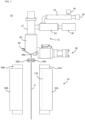
- a molding apparatus 10 of a first embodiment of the present invention includes a resin feeder 12 and a mold unit 14.
- the resin feeder 12 is provided with an extruder 18 including a hopper 16 and a hydraulic motor 20. Inside the extruder 18, there is provided a screw (not shown) connected to a hydraulic motor 20, which melts and kneads a resin fed from the hopper 16.
- the extruder 18 is connected to an accumulator 24 including a plunger 26.
- the accumulator 24 is connected to a T-die 28 via a valve 27.
- the T-die 28 is provided with a die bolt 46 for adjusting a clearance amount S (see Fig. 3 ) of a slit of a die lip 28a of the T-die 28.
- the die lip 28a of the T-die 28 is opened and closed by a die lip opening/closing device 50, which will be described in detail below.
- the resin is melted and kneaded in the extruder 18, and the accumulator 24 is filled with the resin.
- the plunger 26 operates such that the T-die 28 resin is filled with the resin filling the accumulator 24 at a high pressure.
- the die lip 28a of the T-die 28 is closed.
- the die lip opening/closing device 50 opens the die lip 28a, and a molten resin sheet P is extruded through the slit of die lip 28a.
- the thermoplastic resin which is the material of the molten resin sheet P, may be selected as desired.
- examples thereof include a material obtained by adding a foaming agent to any one of polyolefins, such as polypropylene and polyethylene, and acrylic derivatives, such as polyamide, polystyrene, and polyvinyl chloride, or a mixture of two or more kinds thereof.
- the molten resin sheet P may be made of a material containing foamed polystyrene and/or foamed polypropylene. Any physical foaming agents, chemical foaming agents, and mixtures thereof may be used as the foaming agent.
- any inorganic physical foaming agents such as air, carbon dioxide gas, nitrogen gas, and water, and organic physical foaming agents such as butane, pentane, hexane, dichloromethane, and dichloroethane, and their supercritical fluids may be used as the physical foaming agent.
- the mold unit 14 is disposed below the T-die 28 and includes molds 32A, 32B disposed to face each other.
- a cavity 116 is formed in the mold 32A.
- Rollers 30A, 30B are provided, below the T-die 28, between the molds 32A, 32B and T-die 28 and, which are disposed to face each other. After being extruded by the resin feeder 12, the molten resin sheet P passes between the rollers 30A, 30B while being fed downward by the rollers 30A, 30B, and is disposed between the molds 32A, 32B. It should be noted that the rollers 30A, 30B may also be eliminated.
- the thickness of the molten resin sheet P may be adjusted by adjusting the opening degree of the die lip 28a, thus eliminating the use of the rollers 30A, 30B. Further, the thickness of the molten resin sheet P may be continuously changed without using the rollers 30A, 30B by continuously changing the opening degree of the die lip 28a while extruding the molten resin sheet P. A gradual increase in the opening degree of the die lip during extrusion can prevent drawdown without using rollers 30A, 30B, thereby allowing the formation of a long molten resin sheet P in the vertical direction.
- a mold frame 33A is provided on an outer periphery of the cavity 116 of the mold 32A.
- a mold frame 33B is provided facing the mold frame 33A.
- the mold frames 33A, 33B are formed in a substantially annular shape and formed so as to be movable in a direction approaching each other.
- the mold frames 33A, 33B contact the molten resin sheet P and sandwich the molten resin sheet P, making the space area enclosed by the mold 32A (cavity 116), the mold frame 33A, and the molten resin sheet P a sealed space.
- the space enclosed by the mold 32B, the mold frame 33B, and the molten resin sheet P is also made a sealed space.
- a pair of molds may be used such that when the molds are closed, the cavity surfaces of the pair are disposed apart at a predetermined distance that is greater than the thickness of the molten resin sheet P.
- the molten resin sheet P is suctioned through minute suction holes provided on the cavity surfaces on both sides.
- This configuration allows the molten resin sheet P to be pulled in the thickness direction, thereby improving the foaming magnification. As a result, a foam molded product with high foaming magnification can be obtained.
- An actuator 51 is fixed to a plate 74 of the frame 70 on the opposite side of the T-die 28.
- the actuator 51 operates under the control of a controller (not shown).
- the actuator 51 is a linear-acting cylinder and includes a cylinder 51a and a piston rod 5 1b.
- the piston rod 51b has a variable protrusion from the cylinder 51a.
- the power of the actuator 51 may be, but not limited to, hydraulic or electric.
- a pusher 1 is provided on the T-die 28 side of the actuator 51.
- the pusher 1 is configured to move linearly, actuated by the actuator 51.
- the die lip 28a of the T-die 28 is configured to open and close in response to the linear motion of the pusher 1.
- the pusher 1 includes a plurality of sub-pushers 6 disposed along the longitudinal direction of the die lip 28a (vertical direction of Fig. 2A ).
- the plurality of sub-pushers 6 are movable independently of each other.
- the sub-pushers 6 each include a bracket 61, a pusher base 62, and a pusher bar 63.
- the pusher base 62 is linked to the piston rod 5 1b via the bracket 61.
- a plurality of substantially cylindrical pusher bars 63 are provided on the T-die 28 side of the pusher base 62.
- two pusher bars 63 are provided for each of the sub-pushers 6 in the longitudinal direction of the pusher base 62, and since there are two sub-pushers 6, a total of four pusher bars 63 are provided.
- each pusher bar 63 is guided by a bushing 73a provided on the bracket 73 so as to be linearly movable.
- a pusher head 63a with an end curved when viewed from the side is formed at an end portion of each pusher bar 63.
- the pusher head 63a is provided in common for all the pusher bars 63, but in the present embodiment, the pusher head 63a is provided individually for each of the pusher bars 63. This configuration prevents the pusher base 62 from tilting due to resin pressure.
- the actuator 51 is provided for each of the sub-pushers 6, and the plurality of actuators 51 operate in conjunction with each other, thereby enabling the linear motion of the pusher 1 constituted by the plurality of sub-pushers 6.
- the pusher 1 is constituted by the plurality of sub-pushers 6, and each sub-pusher 6 is provided with the actuator 51.
- the sub-pushers 6 in the longitudinal direction have a length shorter than that of the pusher and are thus hardly tilted by the resin pressure from resin in the T-die 28, preventing wear and damage on the actuator 51.
- the pusher 1 tends to be tilted due to deviations in the operation timing of the actuators 51; however, by constituting the pusher 1 with a plurality of sub-pushers 6, tilting of the pusher 1 due to deviations in operation timing can be prevented.
- the pusher base 62 is connected to a position detection sensor 100.
- the position detection sensor 100 may be an eddy current type displacement sensor and be capable of detecting the position of the pusher 1.
- Other types of sensors, such as proximity sensors, can be used as the position detection sensor 100.
- the T-die 28 is provided with a receiving piece 80 corresponding to the pusher bar 63.
- the plurality (four in the present embodiment) of pusher bars 63 and the receiving pieces 80 are each symmetrically disposed with respect to the longitudinal direction of the central plane C of the die lip 28a. This configuration makes it easier to apply pressure evenly to the die lip 28a.
- the receiving piece 80 is provided with an accommodating recess 80a for accommodating the pusher head 63a.
- a bottom of the accommodating recess 80a has a shape substantially complementary to the end of the pusher head 63a.
- the end of the pusher head 63a is curved, and the bottom of the accommodating recess 80a is curved in a similar manner.
- the end of the pusher head 63a and the bottom of the accommodating recess 80a are cylindrically curved.
- the pusher head 63a is sandwiched between an upper wall 80b and a lower wall 80c in the accommodating recess 80a.
- This configuration keeps the pusher head 63a from rattling in the vertical direction within the accommodating recess 80a and stably holds the pusher head 63a.
- the accommodating recess 80a extends toward the entrance side (pusher head 63a side) (that is, the length in the vertical direction of the accommodating recess 80a is longer), and the upper wall 80b and the lower wall 80c do not contact the pusher head 63a in the vicinity of the entrance of the accommodating recess 80a. This configuration makes it easier to accommodate the pusher head 63a in the accommodating recess 80a.
- the receiving piece 80 is connected to the die lip piece 81 provided in the die lip 28a.
- the die lip piece 81 includes a bending portion 81a formed into a thin wall with a large substantially rectangular parallelepiped block cut out, a receiving piece connection 81b to which the receiving piece 80 is attached, and a fixing portion 81c fixed to a body of the T-die 28. That is, the receiving piece connection 81b and the fixing portion 81c are connected by the bending portion 81a.
- the opening/closing structure W configured to open and close the slit of the die lip 28a, indicated by the clearance amount S, includes the receiving piece 80 and the die lip piece 81.
- the die lip 28a and the die lip piece 81 are sandwiched by a pair of side plates 75, and the slit of the die lip 28a is opened and closed while being guided by the side plates 75. This configuration enables stable opening and closing of the slit.
- the die lip opening/closing device 50 operates as follows. In the case of filling the accumulator 24 or the T-die 28 with molten resin, the slit of the die lip 28a is required to be closed. In this case, each actuator 51 advances (linearly moves in the direction of T-die 28) each sub-pusher 6. When the pusher head 63a of the sub-pusher 6 advances, the pusher head 63a presses the receiving piece connection 81b through the receiving piece 80, and this causes the bending portion 81a to bend and the receiving piece connection 81b to rotate downward around the bending portion 81a portion. Then, the clearance amount S of the slit is reduced reaching to 0. In other words, the die lip 28a is closed.
- each actuator 51 retracts each sub-pusher 6.
- the pusher head 63a of the sub-pusher 6 retracts, the pressure of the receiving piece 80 by the pusher head 63a is released, and the receiving piece 80 and the receiving piece connection 81b return by the restoring force of the bending portion 81a of the die lip piece 81, allowing the die lip 28a (slit) to open.
- the pusher head 63a is provided individually for each of the pusher bar 63, but the pusher head 63a may be provided in common for each of the plurality of pusher bars 63 belonging to the same sub-pusher 6.
- a first pusher head common to two upper pusher bars 63 and a second pusher head common to two lower pusher bars 63 may be provided.
- the significance of constituting the pusher 1 with the plurality of sub-pushers 6 is hardly lost, and the number of components can be reduced.
Landscapes
- Engineering & Computer Science (AREA)
- Mechanical Engineering (AREA)
- Manufacturing & Machinery (AREA)
- Extrusion Moulding Of Plastics Or The Like (AREA)
Abstract
Description
- The present invention relates to a die lip opening/closing device.
-
Patent Literature 1 discloses a die lip opening/closing device configured to open and close a die lip of a T-die by linearly moving a pusher. - [Patent Literature 1]
JP-A-2020-116846 - The pusher of
Patent Literature 1 has an elongated shape extending along the longitudinal direction of the die lip. Resin pressure from the resin in the T-die is applied to the pusher, but this pressure may not be applied evenly along the longitudinal direction of the die lip, which may cause the pusher to tilt. In addition, when forces applied to the pusher while the pusher is tilted are transmitted to an actuator, the actuator may be easily worn or damaged. - The present invention has been made in view of such circumstances, and an object thereof is to provide a die lip opening/closing device capable of preventing wear and damage on an actuator of a pusher.
- According to the present invention, there is provided a die lip opening/closing device, the device including an opening/closing structure configured to open and close a die lip of a T-die in response to a linear motion of a pusher, and an actuator configured to actuate the pusher to move linearly, wherein the pusher includes a plurality of sub-pushers disposed along a longitudinal direction of the die lip, and the actuator is provided for each of the sub-pushers.
- In the die lip opening/closing device of the present invention, the pusher is constituted by a plurality of sub-pushers, and the actuator is provided for each sub-pusher. The sub-pushers in the longitudinal direction have a length shorter than that of the pusher, and are thus hardly tilted by the resin pressure from resin in the T-die, preventing wear and damage on the actuator. Further, when a plurality of actuators are provided on one pusher without dividing the pusher, the pusher tends to be tilted due to deviations in the operation timing of the actuators; however, by constituting the pusher with a plurality of sub-pushers, tilting of the pusher due to deviations in operation timing can be prevented.
- Hereinafter, various embodiments of the present invention will be presented by way of example. The following embodiments may be combined with each other.
- Preferably, in the die lip opening/closing device described above, the actuator is constituted by a linear-acting cylinder.
-
-
Fig. 1 is a schematic diagram showing amolding apparatus 10 including a die lip opening/closing device 50 of a first embodiment of the present invention. -
Fig. 2A is a bottom view of a main portion of the die lip opening/closing device 50 ofFig. 1 ; andFig. 2B is a front view of the die lip opening/closing device 50, showing a B-B cross-section inFig. 2A for partial components. -
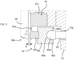
Fig. 3 is an enlarged view of a region A inFig. 2B . - Embodiments of the present invention will be described below. Various characteristic features shown in the following embodiments may be combined with each other. In addition, the scope of the present invention is established independently for each of the features.
- As shown in
Figs. 1 to 2 , amolding apparatus 10 of a first embodiment of the present invention includes aresin feeder 12 and amold unit 14. Theresin feeder 12 is provided with anextruder 18 including ahopper 16 and ahydraulic motor 20. Inside theextruder 18, there is provided a screw (not shown) connected to ahydraulic motor 20, which melts and kneads a resin fed from thehopper 16. - The
extruder 18 is connected to anaccumulator 24 including aplunger 26. Theaccumulator 24 is connected to a T-die 28 via avalve 27. The T-die 28 is provided with adie bolt 46 for adjusting a clearance amount S (seeFig. 3 ) of a slit of adie lip 28a of the T-die 28. Thedie lip 28a of the T-die 28 is opened and closed by a die lip opening/closing device 50, which will be described in detail below. - The resin is melted and kneaded in the
extruder 18, and theaccumulator 24 is filled with the resin. Theplunger 26 operates such that the T-die 28 resin is filled with the resin filling theaccumulator 24 at a high pressure. During the filling of the T-die 28 with molten resin, thedie lip 28a of the T-die 28 is closed. When theaccumulator 24 and T-die 28 are sufficiently filled with the amount of molten resin required for molding, the die lip opening/closing device 50 opens thedie lip 28a, and a molten resin sheet P is extruded through the slit ofdie lip 28a. - The thermoplastic resin, which is the material of the molten resin sheet P, may be selected as desired. Examples thereof include a material obtained by adding a foaming agent to any one of polyolefins, such as polypropylene and polyethylene, and acrylic derivatives, such as polyamide, polystyrene, and polyvinyl chloride, or a mixture of two or more kinds thereof. For example, the molten resin sheet P may be made of a material containing foamed polystyrene and/or foamed polypropylene. Any physical foaming agents, chemical foaming agents, and mixtures thereof may be used as the foaming agent. Any inorganic physical foaming agents such as air, carbon dioxide gas, nitrogen gas, and water, and organic physical foaming agents such as butane, pentane, hexane, dichloromethane, and dichloroethane, and their supercritical fluids may be used as the physical foaming agent.
- The
mold unit 14 is disposed below the T-die 28 and includesmolds cavity 116 is formed in themold 32A.Rollers die 28, between themolds resin feeder 12, the molten resin sheet P passes between therollers rollers molds rollers rollers die lip 28a, thus eliminating the use of therollers rollers die lip 28a while extruding the molten resin sheet P. A gradual increase in the opening degree of the die lip during extrusion can prevent drawdown without usingrollers - A
mold frame 33A is provided on an outer periphery of thecavity 116 of themold 32A. On themold 32B, amold frame 33B is provided facing themold frame 33A. The mold frames 33A, 33B are formed in a substantially annular shape and formed so as to be movable in a direction approaching each other. The mold frames 33A, 33B contact the molten resin sheet P and sandwich the molten resin sheet P, making the space area enclosed by themold 32A (cavity 116), themold frame 33A, and the molten resin sheet P a sealed space. As necessary for molding, the space enclosed by themold 32B, themold frame 33B, and the molten resin sheet P is also made a sealed space. Then, when themolds cavity 116, and the like is depressurized by a vacuum pump (not shown) to form the molten resin sheet P into the shape of thecavity 116. At this time, pressurized fluid may be fed into the space enclosed by themold 32B, themold frame 33B, and the molten resin sheet P. Incidentally, in addition to the molds (molds - Next, the die lip opening/
closing device 50 will be described in detail with reference toFig. 2 . Upper andlower plates frame 70 of the die lip opening/closing device 50 are fixedly provided to the T-die 28 via abracket 73. It should be noted that the upper andlower plates frame 70 shown inFig. 2B are omitted inFig. 2A . - An
actuator 51 is fixed to aplate 74 of theframe 70 on the opposite side of the T-die 28. Theactuator 51 operates under the control of a controller (not shown). In the present embodiment, theactuator 51 is a linear-acting cylinder and includes acylinder 51a and a piston rod 5 1b. Thepiston rod 51b has a variable protrusion from thecylinder 51a. The power of theactuator 51 may be, but not limited to, hydraulic or electric. - A
pusher 1 is provided on the T-die 28 side of theactuator 51. Thepusher 1 is configured to move linearly, actuated by theactuator 51. Thedie lip 28a of the T-die 28 is configured to open and close in response to the linear motion of thepusher 1. - The
pusher 1 includes a plurality ofsub-pushers 6 disposed along the longitudinal direction of thedie lip 28a (vertical direction ofFig. 2A ). The plurality ofsub-pushers 6 are movable independently of each other. Thesub-pushers 6 each include abracket 61, apusher base 62, and apusher bar 63. - The
pusher base 62 is linked to the piston rod 5 1b via thebracket 61. A plurality of substantially cylindrical pusher bars 63 are provided on the T-die 28 side of thepusher base 62. In the present embodiment, twopusher bars 63 are provided for each of thesub-pushers 6 in the longitudinal direction of thepusher base 62, and since there are twosub-pushers 6, a total of fourpusher bars 63 are provided. As shown inFig. 3 , eachpusher bar 63 is guided by abushing 73a provided on thebracket 73 so as to be linearly movable. Apusher head 63a with an end curved when viewed from the side is formed at an end portion of eachpusher bar 63. InPatent Literature 1, thepusher head 63a is provided in common for all the pusher bars 63, but in the present embodiment, thepusher head 63a is provided individually for each of the pusher bars 63. This configuration prevents thepusher base 62 from tilting due to resin pressure. - The
actuator 51 is provided for each of thesub-pushers 6, and the plurality ofactuators 51 operate in conjunction with each other, thereby enabling the linear motion of thepusher 1 constituted by the plurality ofsub-pushers 6. As such, in the die lip opening/closing device 50 of the present embodiment, thepusher 1 is constituted by the plurality ofsub-pushers 6, and each sub-pusher 6 is provided with theactuator 51. Thesub-pushers 6 in the longitudinal direction have a length shorter than that of the pusher and are thus hardly tilted by the resin pressure from resin in the T-die 28, preventing wear and damage on theactuator 51. Further, when a plurality ofactuators 51 are provided on onepusher 1 without dividing thepusher 1, thepusher 1 tends to be tilted due to deviations in the operation timing of theactuators 51; however, by constituting thepusher 1 with a plurality ofsub-pushers 6, tilting of thepusher 1 due to deviations in operation timing can be prevented. - As shown in
Fig. 2B , thepusher base 62 is connected to aposition detection sensor 100. Theposition detection sensor 100 may be an eddy current type displacement sensor and be capable of detecting the position of thepusher 1. Other types of sensors, such as proximity sensors, can be used as theposition detection sensor 100. - As shown in
Figs. 2A and3 , the T-die 28 is provided with a receivingpiece 80 corresponding to thepusher bar 63. The plurality (four in the present embodiment) of pusher bars 63 and the receivingpieces 80 are each symmetrically disposed with respect to the longitudinal direction of the central plane C of thedie lip 28a. This configuration makes it easier to apply pressure evenly to thedie lip 28a. - As shown in
Fig. 3 , the receivingpiece 80 is provided with anaccommodating recess 80a for accommodating thepusher head 63a. A bottom of theaccommodating recess 80a has a shape substantially complementary to the end of thepusher head 63a. To be more specific, the end of thepusher head 63a is curved, and the bottom of theaccommodating recess 80a is curved in a similar manner. Preferably, the end of thepusher head 63a and the bottom of theaccommodating recess 80a are cylindrically curved. Thepusher head 63a is sandwiched between anupper wall 80b and alower wall 80c in theaccommodating recess 80a. This configuration keeps thepusher head 63a from rattling in the vertical direction within theaccommodating recess 80a and stably holds thepusher head 63a. As shown inFig. 3 , theaccommodating recess 80a extends toward the entrance side (pusher head 63a side) (that is, the length in the vertical direction of theaccommodating recess 80a is longer), and theupper wall 80b and thelower wall 80c do not contact thepusher head 63a in the vicinity of the entrance of theaccommodating recess 80a. This configuration makes it easier to accommodate thepusher head 63a in theaccommodating recess 80a. - The receiving
piece 80 is connected to thedie lip piece 81 provided in thedie lip 28a. Thedie lip piece 81 includes a bendingportion 81a formed into a thin wall with a large substantially rectangular parallelepiped block cut out, a receivingpiece connection 81b to which the receivingpiece 80 is attached, and a fixingportion 81c fixed to a body of the T-die 28. That is, the receivingpiece connection 81b and the fixingportion 81c are connected by the bendingportion 81a. The opening/closing structure W configured to open and close the slit of thedie lip 28a, indicated by the clearance amount S, includes the receivingpiece 80 and thedie lip piece 81. - The
die lip 28a and thedie lip piece 81 are sandwiched by a pair ofside plates 75, and the slit of thedie lip 28a is opened and closed while being guided by theside plates 75. This configuration enables stable opening and closing of the slit. - The die lip opening/
closing device 50 operates as follows. In the case of filling theaccumulator 24 or the T-die 28 with molten resin, the slit of thedie lip 28a is required to be closed. In this case, each actuator 51 advances (linearly moves in the direction of T-die 28) eachsub-pusher 6. When thepusher head 63a of the sub-pusher 6 advances, thepusher head 63a presses the receivingpiece connection 81b through the receivingpiece 80, and this causes the bendingportion 81a to bend and the receivingpiece connection 81b to rotate downward around the bendingportion 81a portion. Then, the clearance amount S of the slit is reduced reaching to 0. In other words, thedie lip 28a is closed. - Also, when the molten resin sheet P is extruded, each actuator 51 retracts each
sub-pusher 6. When thepusher head 63a of thesub-pusher 6 retracts, the pressure of the receivingpiece 80 by thepusher head 63a is released, and the receivingpiece 80 and the receivingpiece connection 81b return by the restoring force of the bendingportion 81a of thedie lip piece 81, allowing thedie lip 28a (slit) to open. -
- · In the above embodiment, the
actuator 51 is a linear-acting cylinder, but it may be an actuator of the form having a motion conversion unit that changes the rotational movement of the drive shaft of the motor to the linear movement of the pusher as inPatent Literature 1. - In the above embodiment, the
pusher head 63a is provided individually for each of thepusher bar 63, but thepusher head 63a may be provided in common for each of the plurality of pusher bars 63 belonging to thesame sub-pusher 6. For example, as shown inFig. 2A , a first pusher head common to two upper pusher bars 63 and a second pusher head common to two lower pusher bars 63 may be provided. In this case, the significance of constituting thepusher 1 with the plurality ofsub-pushers 6 is hardly lost, and the number of components can be reduced. - 1: pusher, 6: sub-pusher, 10: molding apparatus, 12: resin feeder, 14: mold unit, 16: hopper, 18: extruder, 20: hydraulic motor, 24: accumulator, 26: plunger, 27: valve, 28: T-die, 28a: die lip, 30A: roller, 30B: roller, 32A: mold, 32B: mold, 33A: mold frame, 33B: mold frame, 46: die bolt, 50: die lip opening/closing device, 51: actuator, 51a: cylinder, 51b: piston rod, 61: bracket, 62: pusher base, 63: pusher bar, 63a: pusher head, 70: frame, 71: plate, 72: plate, 73: bracket, 73a: bushing, 74: plate, 75: side plate, 80: receiving piece, 80a: accommodating recess, 80b: upper wall, 80c: lower wall, 81: die lip piece, 81a: bending portion, 81b: receiving piece connection, 81c: fixing portion, 100: position detection sensor, 116: cavity, P: molten resin sheet, S: clearance amount, W: opening/closing structure
Claims (2)
- A die lip opening/closing device comprising:an opening/closing structure configured to open and close a die lip of a T-die in response to a linear motion of a pusher; andan actuator configured to actuate the pusher to move linearly,wherein the pusher comprises a plurality of sub-pushers disposed along a longitudinal direction of the die lip, andthe actuator is provided for each of the sub-pushers.
- The die lip opening/closing device of Claim 1,
wherein the actuator is constituted by a linear-acting cylinder.
Applications Claiming Priority (2)
| Application Number | Priority Date | Filing Date | Title |
|---|---|---|---|
| JP2021086451A JP7719353B2 (en) | 2021-05-21 | 2021-05-21 | Resin supply device, die lip opening and closing device |
| PCT/JP2022/016327 WO2022244524A1 (en) | 2021-05-21 | 2022-03-30 | Die lip opening/closing device |
Publications (2)
| Publication Number | Publication Date |
|---|---|
| EP4338929A1 true EP4338929A1 (en) | 2024-03-20 |
| EP4338929A4 EP4338929A4 (en) | 2024-10-23 |
Family
ID=84141247
Family Applications (1)
| Application Number | Title | Priority Date | Filing Date |
|---|---|---|---|
| EP22804440.0A Pending EP4338929A4 (en) | 2021-05-21 | 2022-03-30 | DEVICE FOR OPENING/CLOSING A NOZZLE LIP |
Country Status (6)
| Country | Link |
|---|---|
| US (1) | US12434418B2 (en) |
| EP (1) | EP4338929A4 (en) |
| JP (1) | JP7719353B2 (en) |
| KR (1) | KR20230154996A (en) |
| CN (1) | CN117120238A (en) |
| WO (1) | WO2022244524A1 (en) |
Family Cites Families (9)
| Publication number | Priority date | Publication date | Assignee | Title |
|---|---|---|---|---|
| JPS61291117A (en) * | 1985-06-19 | 1986-12-20 | Toshiba Mach Co Ltd | T die for extrusion molding |
| US4704083A (en) | 1985-06-19 | 1987-11-03 | Toshiba Kikai Kabushiki Kaisha | T-dies adapted for extrusion molding |
| JPS63246223A (en) * | 1987-04-02 | 1988-10-13 | Johoku Seikosho:Kk | Lip width control device for t-die |
| DE19535930C1 (en) * | 1995-09-27 | 1997-01-09 | Heinz Dr Ing Gros | Device for variably delimiting a flat flow channel and method for discharging a mass track with variable geometry |
| DE102010018527A1 (en) | 2010-04-27 | 2011-10-27 | Kautex Textron Gmbh & Co. Kg | Process for the production of hollow bodies made of thermoplastic material |
| JP5651504B2 (en) * | 2011-03-08 | 2015-01-14 | 東洋ゴム工業株式会社 | Sheet rubber molding apparatus and method |
| WO2012170713A1 (en) * | 2011-06-07 | 2012-12-13 | 3M Innovative Properties Company | Slot die position adjustment |
| JP7138285B2 (en) | 2019-01-24 | 2022-09-16 | キョーラク株式会社 | Die lip opening and closing device |
| WO2020153436A1 (en) * | 2019-01-24 | 2020-07-30 | キョーラク株式会社 | Die lip opening/closing device and method for manufacturing molded body |
-
2021
- 2021-05-21 JP JP2021086451A patent/JP7719353B2/en active Active
-
2022
- 2022-03-30 CN CN202280027682.8A patent/CN117120238A/en active Pending
- 2022-03-30 KR KR1020237034685A patent/KR20230154996A/en active Pending
- 2022-03-30 EP EP22804440.0A patent/EP4338929A4/en active Pending
- 2022-03-30 WO PCT/JP2022/016327 patent/WO2022244524A1/en not_active Ceased
- 2022-03-30 US US18/560,762 patent/US12434418B2/en active Active
Also Published As
| Publication number | Publication date |
|---|---|
| JP7719353B2 (en) | 2025-08-06 |
| US20240246278A1 (en) | 2024-07-25 |
| WO2022244524A1 (en) | 2022-11-24 |
| JP2022179163A (en) | 2022-12-02 |
| EP4338929A4 (en) | 2024-10-23 |
| CN117120238A (en) | 2023-11-24 |
| KR20230154996A (en) | 2023-11-09 |
| US12434418B2 (en) | 2025-10-07 |
Similar Documents
| Publication | Publication Date | Title |
|---|---|---|
| US5074772A (en) | Mold for injection molded parts made of plasticizable material | |
| CN111417502B (en) | Blow molding device | |
| US3317955A (en) | Apparatus for blow molding hollow containers | |
| CA2295121A1 (en) | Metal mold driving device for molding, holding device, and holding method | |
| JP2788324B2 (en) | Gas shut-off valve and method for controlling plastic processing equipment equipped with the gas shut-off valve | |
| CA2312229A1 (en) | Hydroforming method and hydroforming device | |
| EP4338929A1 (en) | Die lip opening/closing device | |
| CN103282184A (en) | Device for blowing containers | |
| JP7138285B2 (en) | Die lip opening and closing device | |
| US2887716A (en) | Apparatus for the manufacture of hollow articles composed of a plastic material | |
| JP5981289B2 (en) | Blow molding machine mold clamping device | |
| US4822274A (en) | Hydraulic clamping unit for a molding apparatus | |
| JP6856123B2 (en) | Mold height change unit, frame drawing machine, and mold height change method | |
| EP2516132A2 (en) | Drive device for an extrusion blow mould | |
| JP6831262B2 (en) | Hollow molding equipment | |
| JP2003145614A (en) | Molding machine | |
| ITTO930197A1 (en) | INJECTION MOLDING MACHINE. | |
| JP4619561B2 (en) | Mold opening and closing device of injection foam molding machine | |
| JP4211555B2 (en) | Core back injection molding method and injection molded article | |
| JP2006334793A (en) | Injection molding equipment for foam molded products | |
| US5238390A (en) | Blow-molding apparatus for fabricating hollow articles from an open-ended tubular body of thermoplastic material | |
| JP2002518204A (en) | Slot die for producing sheets from foamed plastic | |
| WO2020153436A1 (en) | Die lip opening/closing device and method for manufacturing molded body | |
| CN113618046A (en) | 5G communication piece mould | |
| JPS61262112A (en) | Injection molding apparatus for preparing bellows molding |
Legal Events
| Date | Code | Title | Description |
|---|---|---|---|
| STAA | Information on the status of an ep patent application or granted ep patent |
Free format text: STATUS: THE INTERNATIONAL PUBLICATION HAS BEEN MADE |
|
| PUAI | Public reference made under article 153(3) epc to a published international application that has entered the european phase |
Free format text: ORIGINAL CODE: 0009012 |
|
| STAA | Information on the status of an ep patent application or granted ep patent |
Free format text: STATUS: REQUEST FOR EXAMINATION WAS MADE |
|
| 17P | Request for examination filed |
Effective date: 20231211 |
|
| AK | Designated contracting states |
Kind code of ref document: A1 Designated state(s): AL AT BE BG CH CY CZ DE DK EE ES FI FR GB GR HR HU IE IS IT LI LT LU LV MC MK MT NL NO PL PT RO RS SE SI SK SM TR |
|
| DAV | Request for validation of the european patent (deleted) | ||
| DAX | Request for extension of the european patent (deleted) | ||
| A4 | Supplementary search report drawn up and despatched |
Effective date: 20240924 |
|
| RIC1 | Information provided on ipc code assigned before grant |
Ipc: B29C 48/475 20190101ALI20240918BHEP Ipc: B29C 48/375 20190101ALI20240918BHEP Ipc: B29C 48/365 20190101ALI20240918BHEP Ipc: B29C 48/305 20190101ALI20240918BHEP Ipc: B29C 48/31 20190101AFI20240918BHEP |