EP4338918A1 - Composite material pulverization device, moving body, and composite material pulverization method - Google Patents
Composite material pulverization device, moving body, and composite material pulverization method Download PDFInfo
- Publication number
- EP4338918A1 EP4338918A1 EP22824506.4A EP22824506A EP4338918A1 EP 4338918 A1 EP4338918 A1 EP 4338918A1 EP 22824506 A EP22824506 A EP 22824506A EP 4338918 A1 EP4338918 A1 EP 4338918A1
- Authority
- EP
- European Patent Office
- Prior art keywords
- composite material
- crushing
- pieces
- dividing
- crushing apparatus
- Prior art date
- Legal status (The legal status is an assumption and is not a legal conclusion. Google has not performed a legal analysis and makes no representation as to the accuracy of the status listed.)
- Pending
Links
Images






Classifications
-
- B—PERFORMING OPERATIONS; TRANSPORTING
- B29—WORKING OF PLASTICS; WORKING OF SUBSTANCES IN A PLASTIC STATE IN GENERAL
- B29B—PREPARATION OR PRETREATMENT OF THE MATERIAL TO BE SHAPED; MAKING GRANULES OR PREFORMS; RECOVERY OF PLASTICS OR OTHER CONSTITUENTS OF WASTE MATERIAL CONTAINING PLASTICS
- B29B17/00—Recovery of plastics or other constituents of waste material containing plastics
- B29B17/04—Disintegrating plastics, e.g. by milling
-
- B—PERFORMING OPERATIONS; TRANSPORTING
- B29—WORKING OF PLASTICS; WORKING OF SUBSTANCES IN A PLASTIC STATE IN GENERAL
- B29B—PREPARATION OR PRETREATMENT OF THE MATERIAL TO BE SHAPED; MAKING GRANULES OR PREFORMS; RECOVERY OF PLASTICS OR OTHER CONSTITUENTS OF WASTE MATERIAL CONTAINING PLASTICS
- B29B17/00—Recovery of plastics or other constituents of waste material containing plastics
- B29B2017/0094—Mobile recycling devices, e.g. devices installed in truck trailers
-
- B—PERFORMING OPERATIONS; TRANSPORTING
- B29—WORKING OF PLASTICS; WORKING OF SUBSTANCES IN A PLASTIC STATE IN GENERAL
- B29B—PREPARATION OR PRETREATMENT OF THE MATERIAL TO BE SHAPED; MAKING GRANULES OR PREFORMS; RECOVERY OF PLASTICS OR OTHER CONSTITUENTS OF WASTE MATERIAL CONTAINING PLASTICS
- B29B17/00—Recovery of plastics or other constituents of waste material containing plastics
- B29B17/04—Disintegrating plastics, e.g. by milling
- B29B2017/0424—Specific disintegrating techniques; devices therefor
- B29B2017/0468—Crushing, i.e. disintegrating into small particles
-
- B—PERFORMING OPERATIONS; TRANSPORTING
- B29—WORKING OF PLASTICS; WORKING OF SUBSTANCES IN A PLASTIC STATE IN GENERAL
- B29K—INDEXING SCHEME ASSOCIATED WITH SUBCLASSES B29B, B29C OR B29D, RELATING TO MOULDING MATERIALS OR TO MATERIALS FOR MOULDS, REINFORCEMENTS, FILLERS OR PREFORMED PARTS, e.g. INSERTS
- B29K2105/00—Condition, form or state of moulded material or of the material to be shaped
- B29K2105/06—Condition, form or state of moulded material or of the material to be shaped containing reinforcements, fillers or inserts
-
- B—PERFORMING OPERATIONS; TRANSPORTING
- B29—WORKING OF PLASTICS; WORKING OF SUBSTANCES IN A PLASTIC STATE IN GENERAL
- B29L—INDEXING SCHEME ASSOCIATED WITH SUBCLASS B29C, RELATING TO PARTICULAR ARTICLES
- B29L2031/00—Other particular articles
- B29L2031/08—Blades for rotors, stators, fans, turbines or the like, e.g. screw propellers
- B29L2031/082—Blades, e.g. for helicopters
- B29L2031/085—Wind turbine blades
-
- B—PERFORMING OPERATIONS; TRANSPORTING
- B63—SHIPS OR OTHER WATERBORNE VESSELS; RELATED EQUIPMENT
- B63B—SHIPS OR OTHER WATERBORNE VESSELS; EQUIPMENT FOR SHIPPING
- B63B35/00—Vessels or similar floating structures specially adapted for specific purposes and not otherwise provided for
- B63B35/44—Floating buildings, stores, drilling platforms, or workshops, e.g. carrying water-oil separating devices
- B63B2035/4473—Floating structures supporting industrial plants, such as factories, refineries, or the like
-
- B—PERFORMING OPERATIONS; TRANSPORTING
- B63—SHIPS OR OTHER WATERBORNE VESSELS; RELATED EQUIPMENT
- B63H—MARINE PROPULSION OR STEERING
- B63H21/00—Use of propulsion power plant or units on vessels
- B63H21/32—Arrangements of propulsion power-unit exhaust uptakes; Funnels peculiar to vessels
-
- Y—GENERAL TAGGING OF NEW TECHNOLOGICAL DEVELOPMENTS; GENERAL TAGGING OF CROSS-SECTIONAL TECHNOLOGIES SPANNING OVER SEVERAL SECTIONS OF THE IPC; TECHNICAL SUBJECTS COVERED BY FORMER USPC CROSS-REFERENCE ART COLLECTIONS [XRACs] AND DIGESTS
- Y02—TECHNOLOGIES OR APPLICATIONS FOR MITIGATION OR ADAPTATION AGAINST CLIMATE CHANGE
- Y02W—CLIMATE CHANGE MITIGATION TECHNOLOGIES RELATED TO WASTEWATER TREATMENT OR WASTE MANAGEMENT
- Y02W30/00—Technologies for solid waste management
- Y02W30/50—Reuse, recycling or recovery technologies
- Y02W30/62—Plastics recycling; Rubber recycling
Definitions
- the present disclosure relates to a composite material crushing apparatus, a moving unit, and a composite material crushing method.
- Patent Literature 1 discloses using a wire saw forced with predetermined tension to cut a cutting target object fixed to a main frame.
- Patent Literature 1 by merely cutting a long composite material at a predetermined position in the longitudinal direction by a wire saw as disclosed in Patent Literature 1, it is not possible to sufficiently reduce the volume of the long composite material because the size of the cut composite materials is relatively large. Further, to reduce the volume after cutting a composite material, it is required to carry the cut composite materials to a crushing apparatus or the like for further reducing the size of the composite materials, which will increase the cost in carrying the composite materials.
- the present disclosure has been made in view of such circumstances and intends to provide a composite material crushing apparatus, a moving unit, and a composite material crushing method that can sufficiently reduce the volume of a long composite material without increasing costs.
- a composite material crushing apparatus includes: a dividing part configured to divide a long composite material into pieces, the composite material being formed of a resin material containing a fiber base material; a conveying part configured to convey the pieces divided by the dividing part; and a crushing part configured to crush the pieces conveyed by the conveying part.
- a composite material crushing method includes: a dividing step of dividing a long composite material into pieces, the composite material being formed of a resin material containing a fiber base material; a transport step of transporting the pieces divided by the dividing step; and a crushing step of crushing the pieces transported by the transport step.
- a composite material crushing apparatus a moving unit, and a composite material crushing method that can sufficiently reduce the volume of a long composite material can be provided.
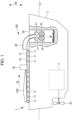
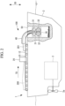
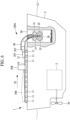
- FIGS. 1 and 2 are partial cross-sectional views showing a ship (moving unit) 1 having a composite material crushing apparatus 100 according to the first embodiment of the present disclosure.
- Fig. 1 shows a state before the composite 200 is cut
- Fig. 2 shows a state before the composite 200 is ground.
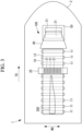
- Fig. 3 is a top view of the composite material crushing apparatus 100 shown in Fig. 1 .
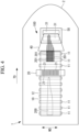
- Fig. 4 is a top view of the composite material crushing apparatus 100 shown in Fig. 2 .
- the volume reduction processing apparatus 100 of the present embodiment is an apparatus for reducing the volume of the long composite material 200.
- the long composite material 200 is an airfoil member used in aircraft wings and renewable energy power generation, for example, wind turbines and tidal power generators.
- the composite material 200 is formed of a resin material including a fiber base material.
- the fiber base material is, for example, a member in which a sheet formed of a reinforcing fiber material such as carbon fiber or glass fiber is laminated over a plurality of layers.
- the fiber base material may be a prepreg previously impregnated or partially impregnated with a resin material, or a combination of the prepreg and the reinforcing fiber material.
- the resin material is, for example, an epoxy resin; a thermosetting resin material such as unsaturated polyester, vinyl ester, phenol, cyanate ester, polyimide, or the like; or a thermoplastic resin such as polyether ether ketone (PEEK), polyethylene terephthalate (PET), polybutylene terephthalate (PBT), nylon 6 (PA6), nylon 66 (PA66), polyphenylene sulfide (PPS), polyetherimide (PEI), polyether ketone ketone (PEKK), or the like.
- PEEK polyether ether ketone
- PET polyethylene terephthalate
- PBT polybutylene terephthalate
- PA6 nylon 6
- PA66 nylon 66
- PPS polyphenylene sulfide
- PEI polyetherimide
- PEKK polyether ketone ketone
- the ship 1 of the present embodiment has a composite material crushing apparatus 100, a body 2 in which the composite material crushing apparatus 100 is installed, and an internal combustion engine (thrust generating device) 3 generating thrust for moving the body 2.
- the internal combustion engine 3 rotates the screw 3a to obtain a thrust force for moving the main body 2.
- the composite material crushing apparatus 100 has a conveying part 10, a cutting part (dividing part) 20, a crushing part 30, a conveying guide 40, and a collection part 50.
- the conveying part 10 is a device that conveys the composite material 200. As illustrated in Fig. 1 , the conveying part 10 has a plurality of rollers 11 and a belt 12 stretched around the plurality of rollers 11. The conveying part 10 transmits drive force from the plurality of rollers 11 to the belt 12 and conveys the composite material 200 to the cutting part 20 along a transport direction TD. Further, the conveying part 10 conveys pieces of the composite material 200, which have been cut by the cutting part 20, toward the crushing part 30. Note that the conveying part 10 may be a part that conveys the composite material 200 by using only the rollers 11 without having the belt 12.
- the cutting part 20 is a device that cuts (divides) the composite material 200 into pieces (for example, the length thereof in the width direction WD is less than or equal to 100 mm). As illustrated in Fig. 3 and Fig. 4 , the cutting part 20 has a plurality of cutting members 21 each extending in the transport direction. The cutting members 21 are arranged spaced apart from each other along the width direction WD orthogonal to the transport direction TD. Each cutting member 21 is, for example, a rounded circular saw that is rotated about an axis, a belt-like band saw that is rotated about an axis, or a wire stretched around so as to be rotated. As the cutting part 20, a water jet cutting device or a laser cutting device may be employed.
- the cutting part 20 is fixed to the body 2 at a predetermined position in the transport direction TD.
- the composite material 200 conveyed along the transport direction TD by the conveying part 10 is cut at a plurality of positions in the width direction WD along the transport direction TD by the cutting members 21 when passing through the cutting part 20 fixed at the predetermined position in the transport direction TD.
- the cutting part 20 cuts the composite material 200 by the plurality of cutting members 21 and thereby divides the composite material 200 into a plurality of pieces 201.
- the crushing part 30 is a device for crushing fragments 201 conveyed by the conveying part 10. As shown in Figs. 1 and 2 , the crushing part 30 has a pair of gripping rollers 31 rotating in opposite directions, and a pair of crushing rollers 32 rotating in opposite directions.
- the pair of gripping rollers 31 are rollers that rotate the pieces 201 of the composite material 200 conveyed through the conveying guide 40 while being tightened by the conveying part 10, and push the pieces 201 into the pair of crushing rollers 32.
- a pair of crushing rollers 32 form a device for crushing a piece 201 of a composite material 200 pressed by a pair of gripping rollers 31.
- a pair of crushing rollers 32 are provided with a plurality of claws (not shown) on the outer peripheral surface thereof, and the pieces 201 of the composite material 200 are crushed by the plurality of claws.
- the pieces 201 crushed by the pair of crushing rollers 32 are crushed to a size of, for example, an average value of 50 mm or less.
- the conveying guide 40 is a casing that guides the pieces 201 of the composite material 200, which have been cut by the cutting part 20, from the conveying part 10 to the crushing part 30. As illustrated in Fig. 1 and Fig. 2 , the conveying guide 40 is formed in a circular arc shape in sectional view so as to guide the pieces 201 of the composite material 200, which have been transported horizontally along the transport direction TD, to the collection part 50 extending in the vertical direction VD. The conveying guide 40 guides the horizontally transported composite material 200 downward along the vertical direction VD.
- the collection part 50 is arranged inside the body 2 and formed in a cylindrical shape along the vertical direction.
- the collection part 50 is a device that collects the pieces 201 of the composite material 200 crushed by the crushing part 30.
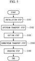
- FIG. 5 is a flowchart illustrating the composite material crushing method of the present embodiment.
- step S101 installation step
- the composite material 200 is installed to the conveying part 10 upstream in the transport direction TD from the cutting part 20.
- the composite material 200 is carried to the conveying part 10 while being suspended by a crane (not illustrated) and is then installed to the conveying part 10.
- step S102 upstream transport step
- the composite material 200 installed to the conveying part 10 is conveyed toward the cutting part 20 upstream in the transport direction TD from the cutting part 20.
- step S103 cutting step
- the composite material 200 is cut into the pieces 201 by the cutting part 20.
- the cutting part 20 cuts the composite material 200 by the cutting members 21 and thereby divides the composite material 200 into the plurality of pieces 201.
- step S104 downstream transport step
- the pieces 201 of the composite material 200 installed to the conveying part 10 are conveyed toward the crushing part 30 downstream in the transport direction TD from the cutting part 20.
- the pieces 201 conveyed by the conveying part 10 are guided by the conveying guide 40 and guided into the pair of gripping rollers 31 of the crushing part 30.
- step S105 crushing step
- the piece 201 of the composite material 200 conveyed in step S104 is crushed.
- a crushing part 30 crushes a piece 201 of a composite material 200 pressed by a pair of gripping rollers 31 using a pair of crushing rollers 32.
- the pieces 201 crushed by the pair of crushing rollers 32 are recovered by a recovery part 50.
- the long composite material 200 is divided into the pieces 201 by the cutting part 20.
- the pieces 201 of the composite material 200, which have been cut by the cutting part 20, are conveyed to the crushing part 30 by the conveying part 10 and crushed by the crushing part 30. Since the composite material 200 cut into the pieces 201 can be conveyed to and crushed by the crushing part 30, it is possible to sufficiently reduce the volume of the long composite material 200 without increasing costs.
- both the composite material 200 before cut by the cutting part 20 and the pieces 201 of the composite material 200 after cut by the cutting part 20 are conveyed by the conveying part 10. Therefore, both the process of using the cutting part 20 to cut the composite material 200 installed to the conveying part 10 into the pieces 201 and the process of using the crushing part 30 to crush the pieces 201 cut by the cutting part 20 can be performed automatically and continuously without intervention of an operator.
- the composite material crushing apparatus 100 of the present embodiment is installed to the watercraft 1 having the internal combustion engine 3 that generates thrust for moving the body 2. It is thus possible to move the composite material crushing apparatus 100 to the place where the composite material 200 is arranged without carrying the long composite material 200 to be crushed to the place where the composite material crushing apparatus 100 is installed. It is thus possible to reduce the cost in carrying the composite material 200 to the place where the composite material crushing apparatus 100 is installed.
- the present embodiment is a modified example for the first embodiment and is the same as the first embodiment except as specifically described below, and the description thereof will be omitted below.
- the cutting part 20 cuts the composite material 200 along the conveying direction TD by cutting members 21 provided at a plurality of positions in the width direction WD.
- the composite material crushing apparatus 100 A of the present embodiment cuts the composite material 200 along the width direction WD by moving the cutting member 21 A along the width direction WD.
- Fig. 6 is a partial sectional view illustrating the watercraft 1 having the composite material crushing apparatus 100A according to the second embodiment of the present disclosure.
- Fig. 7 is a plan view of the composite material crushing apparatus 100A illustrated in Fig. 6 when viewed from above. As illustrated in Fig. 6 and Fig. 7 , the composite material crushing apparatus 100A has a cutting part 20A fixed to the body 2 at a predetermined position in the transport direction TD.
- the cutting part 20A is a device that cuts (divides) the composite material 200 into pieces (for example, the length thereof in the transport direction TD is 5 m or less). As illustrated in Fig. 7 , the cutting part 20A has a plurality of cutting members 21A extending in the width direction WD. The cutting members 21A are configured to move along the width direction WD. Each cutting member 21A is, for example, a rounded circular saw that is rotated about an axis or a belt-like band saw that is rotated about an axis.
- the cutting part 20A is fixed to the body 2 at a predetermined position in the transport direction TD.
- the composite material 200 conveyed along the transport direction TD by the conveying part 10 is cut at a plurality of positions in the transport direction TD along the width direction WD by the cutting members 21A when passing through the cutting part 20A fixed at the predetermined position in the transport direction TD.
- the cutting part 20A cuts the composite material 200 at a plurality of positions in the transport direction TD by the cutting members 21A and thereby divides the composite material 200 into a plurality of pieces 201.
- the cutting part 20A is fixed to the body 2 at a predetermined position in the transport direction TD, it is desirable to temporarily suspend the motion in the transport direction TD of the composite material 200 performed by the conveying part 10 when the composite material 200 is being cut by the cutting members 21A.
- a motion mechanism (not illustrated) that moves the cutting part 20A along the transport direction TD may be provided.
- the cutting part 20A is moved along the transport direction TD at the same speed as the composite material 200, it is not necessary to temporarily suspend the motion in the transport direction TD of the composite material 200 performed by the conveying part 10 when the composite material 200 is being cut by the cutting part 20A. That is, the composite material 200 may be cut by the cutting part 20A while the composite material 200 is being moved by the conveying part 10.
- a modified example may be employed in which turning mechanisms 60 that turn the orientation of the pieces 201 of the composite material 200 conveyed by the conveying part 10 both downstream in the transport direction TD of the cutting part 20A and upstream in the transport direction TD of the crushing part 30 is provided.
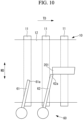
- Fig. 8 to Fig. 10 are plan views illustrating this modified example for the second embodiment of the present disclosure.
- the turning mechanism 60 of the modified example for the present embodiment has a first rotary bar 61 and a second rotary bar 62 arranged downstream in the transport direction TD from the first rotary bar 61.
- the first rotary bar 61 and the second rotary bar 62 are fixed to the body 2 at predetermined positions in the transport direction TD.
- the first rotary bar 61 and the second rotary bar 62 are members installed so as to extend in the horizontal direction above the belt 12.
- the directions in which the first rotary bar 61 and the second rotary bar 62 extend are fixed at predefined angles relative to the transport direction TD.
- the position of a tip 62a of the second rotary bar 62 is a position closer to the center in the width direction WD of the belt 12 than a tip 61a of the first rotary bar 61. That is, the position of the tip 62a of the second rotary bar 62 more protrudes toward the center in the width direction WD of the belt 12 than the position of the tip 61a of the first rotary bar 61.
- Fig. 8 to Fig. 10 illustrate a temporal change of the orientation of the piece 201 of the composite material 200 conveyed by the conveying part 10 from upstream in the transport direction TD.
- the piece 201 first comes into contact with the tip 61a of the first rotary bar 61 and is rotated clockwise on the belt 12 into the state illustrated in Fig. 9 .
- the piece 201 comes into contact with the tip 62a of the second rotary bar 62 and is rotated clockwise on the belt 12 into the state illustrated in Fig. 10 .
- the piece 201 by causing the piece 201 to come into contact with the first rotary bar 61 and the second rotary bar 62 while conveying the piece 201 by the conveying part 10, it is possible to turn the orientation of the piece 201 relative to the transport direction TD by substantially 90 degrees.
- the turning mechanism 60 By using the turning mechanism 60 to turn the orientation of the piece 201 relative to the transport direction TD by substantially 90 degrees, it is possible to have a shorter length in the width direction WD of the piece 201. This makes it possible to reliably arrange the piece 201 at the center in the width direction WD on the belt 12 and improve the crushing efficiency in the crushing part 30. Further, for example, when a region in the width direction WD that can be crushed by the crushing part 30 is predefined, it is possible to reliably transport the piece 201 to the region in the width direction WD that can be crushed by the crushing part 30.
- first rotary bar 61 and the second rotary bar 62 are fixed at angles predefined relative to the transport direction TD in the above description, other forms may be employed.
- first rotary bar 61 and the second rotary bar 62 may be rotated counterclockwise. In such a case, the angle at which the piece 201 can be rotated by a single rotary bar can be increased.
- the number of rotary bars may be any number of one or greater without being limited to two.
- the present embodiment is a modified example for the first embodiment and the second embodiment and is the same as the first embodiment and the second embodiment except as specifically described below, and the description thereof will be omitted below.
- the composite material crushing apparatus of the present embodiment has a destruction part 70 that partially destroys the composite material 200 cut by the cutting part 20 before supplied to the crushing part 30.
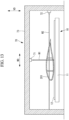
- Fig. 11 is a plan view of the destruction part 70 of the composite material crushing apparatus according to a first example of the third embodiment of the present disclosure when viewed from above.
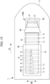
- Fig. 12 is a plan view of the destruction part 70 of the composite material crushing apparatus according to a second example of the third embodiment of the present disclosure when viewed from above.
- Fig. 13 is a sectional view viewed along the line A-A illustrating the destruction part 70 of Fig. 12 .
- the destruction parts 70 illustrated in Fig. 11 and Fig. 12 have the same structure.
- the destruction part 70 illustrated in Fig. 11 is arranged downstream of the cutting part 20 and upstream of the crushing part 30 of the first embodiment.
- the conveying part 10 illustrated in Fig. 11 transports the piece 201 cut by the cutting part 20 to the destruction part 70. Further, the conveying part 10 illustrated in Fig. 11 conveys the piece 201 destroyed by the destruction part 70 to the crushing part 30.
- the destruction part 70 illustrated in Fig. 12 is arranged downstream of the cutting part 20A and upstream of the crushing part 30 of the second embodiment.
- the conveying part 10 illustrated in Fig. 12 conveys the piece 201 cut by the cutting part 20A to the destruction part 70. Further, the conveying part 10 illustrated in Fig. 12 conveys the piece 201 destroyed by the destruction part 70 to the crushing part 30.
- the destruction part 70 is, for example, a water jet injection device that partially destroys the piece 201 of the composite material 200 by a water flow.
- the destruction part 70 illustrated in Fig. 13 has both a first injection part 71 that can move in the width direction WD and a second injection part 72 that can move in the vertical direction VD.
- the first injection part 71 and the second injection part 72 are mounted on a gate-shaped casing 73 arranged so as to cover the conveying part 10.
- the first injection part 71 partially destroys the piece 201 by injecting a water flow W1 from above to below in the vertical direction VD at any position in the width direction WD.
- the first injection part 71 forms, in the piece 201, a through hole penetrating the piece 201 along the vertical direction VD.
- the second injection part 72 partially destroys the piece 201 by injecting a water flow W2 along the width direction WD at any position in the width direction WD.
- the second injection part 72 forms, in the piece 201, a through hole penetrating the piece 201 along the width direction WD.
- the destruction part 70 may have only any one of the first injection part 71 and the second injection part 72.
- the destruction part 70 of the present embodiment may be a destruction part 70A of a modified example illustrated in Fig. 14 .
- the destruction part 70A of the modified example has an injection part 71A that injects a water flow W and an arch-shaped casing 73A arranged so as to cover the conveying part 10.
- the injection part 71A is mounted on the casing 73A.
- the injection part 71A of the destruction part 70A of the modified example can move along the inner circumferential surface of the casing 73A. As illustrated in Fig. 14 , the injection part 71A injects the water flow W from any position in the width direction WD and forms a through hole in the piece 201.
- a destruction step of partially destroying the piece 201 by the destruction part 70, 70A is performed between step S103 (cutting step) and step S105 (crushing step) of the first embodiment.
- a first transport step of transporting the piece 201 cut by step S103 (cutting step) from the cutting part 20, 20A to the destruction part 70, 70A and a second transport step of transporting the piece 201 partially destroyed by the destruction step from the destruction part 70, 70A to the crushing part 30 are performed.
- the composite material crushing apparatus of the present embodiment since the piece 201 cut by the cutting part 20, 20A is partially destroyed by the destruction part 70, 70A, the crushing efficiency of the piece 201 by the crushing part 30 can be increased, and the composite material 200 can be more reliably reduced in volume.
- the destruction parts 70, 70A each are a water jet injection device in the above description, other forms may be employed.
- a press machine that destroys the piece 201 by a pressure may be used as the destruction part 70, 70A.
- a device having a crusher that clamps and destroys the piece 201 may be used.
- the present embodiment is a modified example for the first embodiment and the second embodiment and is the same as the first embodiment and the second embodiment except as specifically described below, and the description thereof will be omitted below.
- the composite material crushing apparatus 100 of the first embodiment cuts the composite material 200 by using the cutting part 20 to cut the composite material 200 into the pieces 201.
- the composite material crushing apparatus 100B of the present embodiment blows up the composite material 200 with an explosive by an explosive part 80 to divide the composite material 200.
- Fig. 15 is a plan view of the composite material crushing apparatus 100B according to the fourth embodiment of the present disclosure when viewed from above.
- the explosive part (dividing part) 80 is arranged upstream in the transport direction TD of the conveying part 10.
- the explosive part 80 has a casing 81 that accommodates the composite material 200 in which explosives B are installed.
- an ignition mechanism (not illustrated) that ignites the explosives B is provided in the casing 81.
- the explosive part 80 ignites the explosives B to divide the composite material 200 into a plurality of pieces 201.
- the casing 81 is for protection to prevent an impact due to ignition of the explosives B from propagating to outside.
- the pieces 201 divided from the composite material 200 by the explosive part 80 are conveyed from the explosive part 80 to the crushing part 30 by the conveying part 10.
- the crushing part 30 crushes the pieces 201 conveyed from the conveying part 10 and supplies the pieces 201 to the collection part 50.
- the long composite material 200 can be blown up and divided by the explosives B, and pieces crushed by the crushing part 30 can be obtained.
- the present embodiment is a modified example for the first embodiment and is the same as the first embodiment except as specifically described below, and the description thereof will be omitted below.
- the composite material crushing apparatus 100C of the present embodiment has a heating part 90 that heats the composite material 200 cut by the cutting part 20.
- the heating part 90 has a casing 91 arranged so as to cover the conveying part 10 and a heater 92 installed inside the casing 91.
- the heater 92 is a device that heats the resin material, which is contained in the composite material 200 installed on the belt 12 of the conveying part 10, to a softening temperature or higher.
- the heater 92 heats the resin material contained in the composite material 200 to the softening temperature or higher to soften the resin material.
- the heater 92 can generate heat by electric power, other forms may be employed.
- exhaust heat may be collected from the internal combustion engine 3 and used as the heat source of the heater 92.
- an incinerator that incinerates fragments of the composite material 200 collected by the collection part 50 may be provided, and heat generated by the incinerator may be collected to be used as the heat source of the heater 92.
- any other heat sources may be used as the heat source of the heater 92.
- the composite material crushing apparatus 100C of the present embodiment since the composite material 200 whose resin material has been softened after heated by the heating part 90 is cut by the cutting part 20, the load required for cutting the composite material 200 by the cutting part 20 can be reduced, and the composite material 200 can be reliably cut into the pieces 201.
- the present embodiment is a modified example for the first embodiment and is the same as the first embodiment except as specifically described below, and the description thereof will be omitted below.
- the composite material crushing apparatus 100 of the first embodiment guides the pieces 201 of the composite material 200 downward along the vertical direction VD by the conveying guide 40 and crushes the pieces 201 by the crushing part 30 installed above the collection part 50.
- the composite material crushing apparatus 100D of the present embodiment has a crushing part 30D arranged on the extension line of the transport direction TD of the conveying part 10.
- the composite material crushing apparatus 100D of the present embodiment has a crushing part 30D.
- the crushing part 30D is a device for crushing pieces 201 conveyed by the conveying part 10.
- the crushing part 30D has a pair of gripping rollers 31D rotating in opposite directions to each other and a pair of crushing rollers 32D rotating in opposite directions to each other.
- the pair of gripping rollers 31D rotate while gripping the piece 201 of the composite material 200 conveyed by the conveying part 10, and push the piece 201 into the pair of gripping rollers 32D.
- the pair of crushing rollers 32D form a device that crushes the pieces 201 of the composite material 200, which have been pushed by the pair of gripping rollers 31D.
- the pair of crushing rollers 32D are provided with a plurality of claws (not illustrated) on their outer circumferential surfaces and collapse and thereby crush the pieces 201 of the composite material 200 by the plurality of claws.
- the pieces 201 of the composite material 200, which have been crushed by the crushing part 30D, are collected by the collection part 50D.
- the crushing part 30D is arranged on the extension line of the transport direction TD of the conveying part 10, it is possible to convey the pieces 201 of the composite material 200 to the crushing part 30D without changing the transport direction TD provided by the conveying part 10 and crush the pieces 201 by the crushing part 30D.
- the composite material crushing apparatus according to the present embodiments described above are understood as follows, for example.
- a composite material crushing apparatus (100) includes: a dividing part (20) configured to divide a long composite material (200) into pieces, the composite material being formed of a resin material containing a fiber base material; a conveying part (10) configured to convey the pieces divided by the dividing part; and a crushing part (30) configured to crush the pieces conveyed by the conveying part.
- a long composite material is divided into pieces by the dividing part.
- the pieces of the composite material, which have been divided by the dividing part, are conveyed to the crushing part by the conveying part and crushed by the crushing part. Since the composite material divided into pieces can be conveyed to and crushed by the crushing part, it is possible to sufficiently reduce the volume of the long composite material without increasing costs.
- the dividing part may be configured to divide the composite material by using a cutting member (21) to cut the composite material.
- a long composite material can be divided by the cutting member into pieces to be crushed by the crushing part.
- the dividing part may be configured to divide the composite material by using an explosive to blow up the composite material.
- a long composite material can be blown up and divided by an explosive, and thereby pieces to be crushed by the crushing part can be obtained.
- the composite material crushing apparatus may be configured to include a destruction part (70) arranged downstream in the transport direction from the dividing part and configured to partially destroy the pieces divided by the dividing part, and the conveying part may be configured to convey the pieces divided by the dividing part to the destruction part and convey the pieces destroyed by the destruction part to the crushing part.
- a destruction part 70
- the conveying part may be configured to convey the pieces divided by the dividing part to the destruction part and convey the pieces destroyed by the destruction part to the crushing part.
- the composite material crushing apparatus of the present configuration since pieces divided by the dividing part are partially destroyed by the destruction part, the crushing efficiency of pieces by the crushing part can be increased, and the composite material can be more reliably reduced in volume.
- the composite material crushing apparatus may be configured to include a heating part (90) configured to heat the composite material to be divided by the dividing part to soften the resin material.
- the composite material crushing apparatus of the present configuration since the composite material whose resin material has been softened after heated by the heating part is divided by the dividing part, the load required for dividing the composite material by the dividing part can be reduced, and the composite material can be reliably cut into the pieces.
- a moving part (1) according to the present disclosure includes: the composite material crushing apparatus according to any one of the above; a body (2) in which the composite material crushing apparatus is installed; and a thrust generation part (3) configured to generate thrust for moving the body.
- the moving part of the present disclosure it is possible to move the composite material crushing apparatus to the place where the composite material is arranged without carrying the long composite material to be crushed to the place where the composite material crushing apparatus is installed. It is thus possible to reduce the cost in carrying the composite material to the place where the composite material crushing apparatus is installed.
- a composite material crushing method includes: a dividing step (S 103) of dividing a long composite material into pieces, the composite material being formed of a resin material containing a fiber base material; a transport step (S 104) of transporting the pieces divided by the dividing step; and a crushing step (S 105) of crushing the pieces transported by the transport step.
- a long composite material is divided into pieces by the dividing part.
- the pieces of the composite material which have been divided by the dividing step, are transported to the crushing part by the transport step and crushed by the crushing step. Since the composite material divided into pieces can be crushed by the crushing step, it is possible to sufficiently reduce the volume of the long composite material without increasing costs.
- the dividing step may be configured to divide the composite material by using a cutting member (21) to cut the composite material.
- a long composite material can be divided by the cutting member into pieces to be crushed by the crushing step.
- the dividing step may be configured to divide the composite material by using an explosive to blow up the composite material.
- a long composite material can be blown up and divided by an explosive, and thereby pieces to be crushed by the crushing step can be obtained.
- the composite material crushing method according to the present disclosure may be configured to include a destruction step of partially destroying the pieces divided by the dividing step, and the transport step may be configured to have a first transport step of transporting the pieces divided by the dividing step and a second transport step of transporting the pieces destroyed by the destruction step.
- the composite material crushing method of the present configuration since pieces divided by the dividing step are partially destroyed by the destruction step, the crushing efficiency of pieces by the crushing step can be increased, and the composite material can be more reliably reduced in volume.
- the composite material crushing method according to the present disclosure may be configured to include a heating step of heating the composite material to be divided by the dividing step to soften the resin material.
- the composite material crushing method of the present configuration since the composite material whose resin material has been softened after heated by the heating step is divided by the dividing step, the load required for dividing the composite material by the dividing step can be reduced, and the composite material can be reliably divided into the pieces.
Landscapes
- Engineering & Computer Science (AREA)
- Environmental & Geological Engineering (AREA)
- Mechanical Engineering (AREA)
- Crushing And Pulverization Processes (AREA)
- Disintegrating Or Milling (AREA)
Abstract
Description
- The present disclosure relates to a composite material crushing apparatus, a moving unit, and a composite material crushing method.
- Conventionally, in dismantling a long composite material of Fiber Reinforced Plastics (FRP) waste ship or the like, it is known to shear the long composite material by a construction machine such as a power shovel or cut the long composite material by a wire saw cutting device or the like (for example, see Patent Literature 1).
Patent Literature 1 discloses using a wire saw forced with predetermined tension to cut a cutting target object fixed to a main frame. - [PTL 1]
Japanese Patent No. 5720037 - However, by merely cutting a long composite material at a predetermined position in the longitudinal direction by a wire saw as disclosed in
Patent Literature 1, it is not possible to sufficiently reduce the volume of the long composite material because the size of the cut composite materials is relatively large. Further, to reduce the volume after cutting a composite material, it is required to carry the cut composite materials to a crushing apparatus or the like for further reducing the size of the composite materials, which will increase the cost in carrying the composite materials. - The present disclosure has been made in view of such circumstances and intends to provide a composite material crushing apparatus, a moving unit, and a composite material crushing method that can sufficiently reduce the volume of a long composite material without increasing costs.
- A composite material crushing apparatus according to the present disclosure includes: a dividing part configured to divide a long composite material into pieces, the composite material being formed of a resin material containing a fiber base material; a conveying part configured to convey the pieces divided by the dividing part; and a crushing part configured to crush the pieces conveyed by the conveying part.
- A composite material crushing method according to the present disclosure includes: a dividing step of dividing a long composite material into pieces, the composite material being formed of a resin material containing a fiber base material; a transport step of transporting the pieces divided by the dividing step; and a crushing step of crushing the pieces transported by the transport step.
- According to the present disclosure, a composite material crushing apparatus, a moving unit, and a composite material crushing method that can sufficiently reduce the volume of a long composite material can be provided.
-
- [
Fig. 1 ]
Fig. 1 is a partial sectional view illustrating a moving unit having a composite material crushing apparatus according to a first embodiment of the present disclosure, which illustrates a state before a composite material is cut. - [
Fig. 2 ]
Fig. 2 is a partial sectional view illustrating the moving unit having the composite material crushing apparatus according to the first embodiment of the present disclosure, which illustrates a state before a composite material is crushed. - [
Fig. 3 ]
Fig. 3 is a plan view of the composite material crushing apparatus illustrated inFig. 1 when viewed from above. - [
Fig. 4 ]
Fig. 4 is a top view of the composite material crushing apparatus illustrated inFig. 2 when viewed from above. - [
Fig. 5 ]
Fig. 5 is a flowchart illustrating a composite material cutting method of the first embodiment of the present disclosure. - [
Fig. 6 ]
Fig. 6 is a partial sectional view illustrating a moving unit having a composite material crushing apparatus according to a second embodiment of the present disclosure. - [
Fig. 7 ]
Fig. 7 is a plan view of the composite material crushing apparatus illustrated inFig. 6 when viewed from above. - [
Fig. 8 ]
Fig. 8 is a plan view illustrating a modified example for the second embodiment of the present disclosure. - [
Fig. 9 ]
Fig. 9 is a plan view illustrating a modified example for the second embodiment of the present disclosure. - [
Fig. 10 ]
Fig. 10 is a plan view illustrating a modified example for the second embodiment of the present disclosure. - [
Fig. 11 ]
Fig. 11 is a plan view of a destruction part of the composite material crushing apparatus according to a first example of a third embodiment of the present disclosure when viewed from above. - [
Fig. 12 ]
Fig. 12 is a plan view of a destruction part of the composite material crushing apparatus according to a second example of the third embodiment of the present disclosure when viewed from above. - [
Fig. 13 ]
Fig. 13 is a sectional view viewed along an arrow A-A illustrating the destruction part ofFig. 12 . - [
Fig. 14 ]
Fig. 14 is a sectional view illustrating a modified example of the destruction part. - [
Fig. 15 ]
Fig. 15 is a plan view of a composite material crushing apparatus according to a fourth embodiment of the present disclosure when viewed from above. - [
Fig. 16 ]
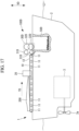
Fig. 16 is a partial sectional view illustrating a moving unit having a composite material crushing apparatus according to a fifth embodiment of the present disclosure. - [
Fig. 17 ]
Fig. 17 is a partial sectional view illustrating a moving unit having a composite material crushing apparatus according to a sixth embodiment of the present disclosure. - Hereinafter, the composite
material crushing apparatus 100 according to the first embodiment of the present disclosure will be described with reference to the drawings.FIGS. 1 and2 are partial cross-sectional views showing a ship (moving unit) 1 having a compositematerial crushing apparatus 100 according to the first embodiment of the present disclosure.Fig. 1 shows a state before thecomposite 200 is cut, andFig. 2 shows a state before thecomposite 200 is ground.Fig. 3 is a top view of the compositematerial crushing apparatus 100 shown inFig. 1 .Fig. 4 is a top view of the compositematerial crushing apparatus 100 shown inFig. 2 . - The volume
reduction processing apparatus 100 of the present embodiment is an apparatus for reducing the volume of the longcomposite material 200. The longcomposite material 200 is an airfoil member used in aircraft wings and renewable energy power generation, for example, wind turbines and tidal power generators. Thecomposite material 200 is formed of a resin material including a fiber base material. The fiber base material is, for example, a member in which a sheet formed of a reinforcing fiber material such as carbon fiber or glass fiber is laminated over a plurality of layers. The fiber base material may be a prepreg previously impregnated or partially impregnated with a resin material, or a combination of the prepreg and the reinforcing fiber material. - The resin material is, for example, an epoxy resin; a thermosetting resin material such as unsaturated polyester, vinyl ester, phenol, cyanate ester, polyimide, or the like; or a thermoplastic resin such as polyether ether ketone (PEEK), polyethylene terephthalate (PET), polybutylene terephthalate (PBT), nylon 6 (PA6), nylon 66 (PA66), polyphenylene sulfide (PPS), polyetherimide (PEI), polyether ketone ketone (PEKK), or the like.
- As shown in
FIG. 1 , theship 1 of the present embodiment has a compositematerial crushing apparatus 100, abody 2 in which the compositematerial crushing apparatus 100 is installed, and an internal combustion engine (thrust generating device) 3 generating thrust for moving thebody 2. Theinternal combustion engine 3 rotates thescrew 3a to obtain a thrust force for moving themain body 2. - As illustrated in
Fig. 1 , the compositematerial crushing apparatus 100 has a conveyingpart 10, a cutting part (dividing part) 20, a crushingpart 30, a conveyingguide 40, and acollection part 50. - The conveying
part 10 is a device that conveys thecomposite material 200. As illustrated inFig. 1 , the conveyingpart 10 has a plurality ofrollers 11 and abelt 12 stretched around the plurality ofrollers 11. The conveyingpart 10 transmits drive force from the plurality ofrollers 11 to thebelt 12 and conveys thecomposite material 200 to the cuttingpart 20 along a transport direction TD. Further, the conveyingpart 10 conveys pieces of thecomposite material 200, which have been cut by the cuttingpart 20, toward the crushingpart 30. Note that the conveyingpart 10 may be a part that conveys thecomposite material 200 by using only therollers 11 without having thebelt 12. - The cutting
part 20 is a device that cuts (divides) thecomposite material 200 into pieces (for example, the length thereof in the width direction WD is less than or equal to 100 mm). As illustrated inFig. 3 andFig. 4 , the cuttingpart 20 has a plurality of cuttingmembers 21 each extending in the transport direction. The cuttingmembers 21 are arranged spaced apart from each other along the width direction WD orthogonal to the transport direction TD. Each cuttingmember 21 is, for example, a rounded circular saw that is rotated about an axis, a belt-like band saw that is rotated about an axis, or a wire stretched around so as to be rotated. As the cuttingpart 20, a water jet cutting device or a laser cutting device may be employed. - The cutting
part 20 is fixed to thebody 2 at a predetermined position in the transport direction TD. Thecomposite material 200 conveyed along the transport direction TD by the conveyingpart 10 is cut at a plurality of positions in the width direction WD along the transport direction TD by the cuttingmembers 21 when passing through the cuttingpart 20 fixed at the predetermined position in the transport direction TD. In such a way, the cuttingpart 20 cuts thecomposite material 200 by the plurality of cuttingmembers 21 and thereby divides thecomposite material 200 into a plurality ofpieces 201. - The crushing
part 30 is a device for crushingfragments 201 conveyed by the conveyingpart 10. As shown inFigs. 1 and2 , the crushingpart 30 has a pair ofgripping rollers 31 rotating in opposite directions, and a pair of crushingrollers 32 rotating in opposite directions. The pair ofgripping rollers 31 are rollers that rotate thepieces 201 of thecomposite material 200 conveyed through the conveyingguide 40 while being tightened by the conveyingpart 10, and push thepieces 201 into the pair of crushingrollers 32. - A pair of crushing
rollers 32 form a device for crushing apiece 201 of acomposite material 200 pressed by a pair ofgripping rollers 31. A pair of crushingrollers 32 are provided with a plurality of claws (not shown) on the outer peripheral surface thereof, and thepieces 201 of thecomposite material 200 are crushed by the plurality of claws. Thepieces 201 crushed by the pair of crushingrollers 32 are crushed to a size of, for example, an average value of 50 mm or less. - The conveying
guide 40 is a casing that guides thepieces 201 of thecomposite material 200, which have been cut by the cuttingpart 20, from the conveyingpart 10 to the crushingpart 30. As illustrated inFig. 1 andFig. 2 , the conveyingguide 40 is formed in a circular arc shape in sectional view so as to guide thepieces 201 of thecomposite material 200, which have been transported horizontally along the transport direction TD, to thecollection part 50 extending in the vertical direction VD. The conveyingguide 40 guides the horizontally transportedcomposite material 200 downward along the vertical direction VD. - The
collection part 50 is arranged inside thebody 2 and formed in a cylindrical shape along the vertical direction. Thecollection part 50 is a device that collects thepieces 201 of thecomposite material 200 crushed by the crushingpart 30. - A composite material crushing method for crushing the
composite material 200 by using the compositematerial crushing apparatus 100 of the present embodiment will now be described with reference to the drawings.Fig. 5 is a flowchart illustrating the composite material crushing method of the present embodiment. - In step S101 (installation step), the
composite material 200 is installed to the conveyingpart 10 upstream in the transport direction TD from the cuttingpart 20. For example, thecomposite material 200 is carried to the conveyingpart 10 while being suspended by a crane (not illustrated) and is then installed to the conveyingpart 10. - In step S102 (upstream transport step), the
composite material 200 installed to the conveyingpart 10 is conveyed toward the cuttingpart 20 upstream in the transport direction TD from the cuttingpart 20. - In step S103 (cutting step), the
composite material 200 is cut into thepieces 201 by the cuttingpart 20. The cuttingpart 20 cuts thecomposite material 200 by the cuttingmembers 21 and thereby divides thecomposite material 200 into the plurality ofpieces 201. - In step S104 (downstream transport step), the
pieces 201 of thecomposite material 200 installed to the conveyingpart 10 are conveyed toward the crushingpart 30 downstream in the transport direction TD from the cuttingpart 20. As illustrated inFig. 4 , thepieces 201 conveyed by the conveyingpart 10 are guided by the conveyingguide 40 and guided into the pair ofgripping rollers 31 of the crushingpart 30. - In step S105 (crushing step), the
piece 201 of thecomposite material 200 conveyed in step S104 is crushed. A crushingpart 30 crushes apiece 201 of acomposite material 200 pressed by a pair ofgripping rollers 31 using a pair of crushingrollers 32. Thepieces 201 crushed by the pair of crushingrollers 32 are recovered by arecovery part 50. - According to the composite
material crushing apparatus 100 of the present embodiment described above, the longcomposite material 200 is divided into thepieces 201 by the cuttingpart 20. Thepieces 201 of thecomposite material 200, which have been cut by the cuttingpart 20, are conveyed to the crushingpart 30 by the conveyingpart 10 and crushed by the crushingpart 30. Since thecomposite material 200 cut into thepieces 201 can be conveyed to and crushed by the crushingpart 30, it is possible to sufficiently reduce the volume of the longcomposite material 200 without increasing costs. - Further, in the composite
material crushing apparatus 100 of the present embodiment, both thecomposite material 200 before cut by the cuttingpart 20 and thepieces 201 of thecomposite material 200 after cut by the cuttingpart 20 are conveyed by the conveyingpart 10. Therefore, both the process of using the cuttingpart 20 to cut thecomposite material 200 installed to the conveyingpart 10 into thepieces 201 and the process of using the crushingpart 30 to crush thepieces 201 cut by the cuttingpart 20 can be performed automatically and continuously without intervention of an operator. - Further, the composite
material crushing apparatus 100 of the present embodiment is installed to thewatercraft 1 having theinternal combustion engine 3 that generates thrust for moving thebody 2. It is thus possible to move the compositematerial crushing apparatus 100 to the place where thecomposite material 200 is arranged without carrying the longcomposite material 200 to be crushed to the place where the compositematerial crushing apparatus 100 is installed. It is thus possible to reduce the cost in carrying thecomposite material 200 to the place where the compositematerial crushing apparatus 100 is installed. - Next, a composite
material crushing apparatus 100A according to the second embodiment of the present disclosure will be described with reference to the drawings. The present embodiment is a modified example for the first embodiment and is the same as the first embodiment except as specifically described below, and the description thereof will be omitted below. - In the composite
material crushing apparatus 100 of the first embodiment, The cuttingpart 20 cuts thecomposite material 200 along the conveying direction TD by cuttingmembers 21 provided at a plurality of positions in the width direction WD. In contrast, the compositematerial crushing apparatus 100 A of the present embodiment cuts thecomposite material 200 along the width direction WD by moving the cuttingmember 21 A along the width direction WD. -
Fig. 6 is a partial sectional view illustrating thewatercraft 1 having the compositematerial crushing apparatus 100A according to the second embodiment of the present disclosure.Fig. 7 is a plan view of the compositematerial crushing apparatus 100A illustrated inFig. 6 when viewed from above. As illustrated inFig. 6 andFig. 7 , the compositematerial crushing apparatus 100A has a cuttingpart 20A fixed to thebody 2 at a predetermined position in the transport direction TD. - The cutting
part 20A is a device that cuts (divides) thecomposite material 200 into pieces (for example, the length thereof in the transport direction TD is 5 m or less). As illustrated inFig. 7 , the cuttingpart 20A has a plurality of cuttingmembers 21A extending in the width direction WD. The cuttingmembers 21A are configured to move along the width direction WD. Each cuttingmember 21A is, for example, a rounded circular saw that is rotated about an axis or a belt-like band saw that is rotated about an axis. - The cutting
part 20A is fixed to thebody 2 at a predetermined position in the transport direction TD. Thecomposite material 200 conveyed along the transport direction TD by the conveyingpart 10 is cut at a plurality of positions in the transport direction TD along the width direction WD by the cuttingmembers 21A when passing through the cuttingpart 20A fixed at the predetermined position in the transport direction TD. In such a way, the cuttingpart 20A cuts thecomposite material 200 at a plurality of positions in the transport direction TD by the cuttingmembers 21A and thereby divides thecomposite material 200 into a plurality ofpieces 201. - Note that, since the cutting
part 20A is fixed to thebody 2 at a predetermined position in the transport direction TD, it is desirable to temporarily suspend the motion in the transport direction TD of thecomposite material 200 performed by the conveyingpart 10 when thecomposite material 200 is being cut by the cuttingmembers 21A. - Further, a motion mechanism (not illustrated) that moves the cutting
part 20A along the transport direction TD may be provided. In such a case, if the cuttingpart 20A is moved along the transport direction TD at the same speed as thecomposite material 200, it is not necessary to temporarily suspend the motion in the transport direction TD of thecomposite material 200 performed by the conveyingpart 10 when thecomposite material 200 is being cut by the cuttingpart 20A. That is, thecomposite material 200 may be cut by the cuttingpart 20A while thecomposite material 200 is being moved by the conveyingpart 10. - Further, in the present embodiment, a modified example may be employed in which
turning mechanisms 60 that turn the orientation of thepieces 201 of thecomposite material 200 conveyed by the conveyingpart 10 both downstream in the transport direction TD of the cuttingpart 20A and upstream in the transport direction TD of the crushingpart 30 is provided.Fig. 8 to Fig. 10 are plan views illustrating this modified example for the second embodiment of the present disclosure. - As illustrated in
Fig. 8 to Fig. 10 , theturning mechanism 60 of the modified example for the present embodiment has a firstrotary bar 61 and a secondrotary bar 62 arranged downstream in the transport direction TD from the firstrotary bar 61. The firstrotary bar 61 and the secondrotary bar 62 are fixed to thebody 2 at predetermined positions in the transport direction TD. The firstrotary bar 61 and the secondrotary bar 62 are members installed so as to extend in the horizontal direction above thebelt 12. The directions in which the firstrotary bar 61 and the secondrotary bar 62 extend are fixed at predefined angles relative to the transport direction TD. - As illustrated in
Fig. 8 to Fig. 10 , in the width direction WD, the position of atip 62a of the secondrotary bar 62 is a position closer to the center in the width direction WD of thebelt 12 than atip 61a of the firstrotary bar 61. That is, the position of thetip 62a of the secondrotary bar 62 more protrudes toward the center in the width direction WD of thebelt 12 than the position of thetip 61a of the firstrotary bar 61. -
Fig. 8 to Fig. 10 illustrate a temporal change of the orientation of thepiece 201 of thecomposite material 200 conveyed by the conveyingpart 10 from upstream in the transport direction TD. As illustrated inFig. 8 , thepiece 201 first comes into contact with thetip 61a of the firstrotary bar 61 and is rotated clockwise on thebelt 12 into the state illustrated inFig. 9 . - After the state illustrated in
Fig. 9 is obtained, thepiece 201 comes into contact with thetip 62a of the secondrotary bar 62 and is rotated clockwise on thebelt 12 into the state illustrated inFig. 10 . As described above, by causing thepiece 201 to come into contact with the firstrotary bar 61 and the secondrotary bar 62 while conveying thepiece 201 by the conveyingpart 10, it is possible to turn the orientation of thepiece 201 relative to the transport direction TD by substantially 90 degrees. - By using the
turning mechanism 60 to turn the orientation of thepiece 201 relative to the transport direction TD by substantially 90 degrees, it is possible to have a shorter length in the width direction WD of thepiece 201. This makes it possible to reliably arrange thepiece 201 at the center in the width direction WD on thebelt 12 and improve the crushing efficiency in the crushingpart 30. Further, for example, when a region in the width direction WD that can be crushed by the crushingpart 30 is predefined, it is possible to reliably transport thepiece 201 to the region in the width direction WD that can be crushed by the crushingpart 30. - Although the first
rotary bar 61 and the secondrotary bar 62 are fixed at angles predefined relative to the transport direction TD in the above description, other forms may be employed. For example, the firstrotary bar 61 and the secondrotary bar 62 may be rotated counterclockwise. In such a case, the angle at which thepiece 201 can be rotated by a single rotary bar can be increased. Further, the number of rotary bars may be any number of one or greater without being limited to two. - Next, a composite material crushing apparatus according to the third embodiment of the present disclosure will be described with reference to the drawings. The present embodiment is a modified example for the first embodiment and the second embodiment and is the same as the first embodiment and the second embodiment except as specifically described below, and the description thereof will be omitted below.
- The composite material crushing apparatus of the present embodiment has a
destruction part 70 that partially destroys thecomposite material 200 cut by the cuttingpart 20 before supplied to the crushingpart 30.Fig. 11 is a plan view of thedestruction part 70 of the composite material crushing apparatus according to a first example of the third embodiment of the present disclosure when viewed from above.Fig. 12 is a plan view of thedestruction part 70 of the composite material crushing apparatus according to a second example of the third embodiment of the present disclosure when viewed from above.Fig. 13 is a sectional view viewed along the line A-A illustrating thedestruction part 70 ofFig. 12 . - The
destruction parts 70 illustrated inFig. 11 andFig. 12 have the same structure. Thedestruction part 70 illustrated inFig. 11 is arranged downstream of the cuttingpart 20 and upstream of the crushingpart 30 of the first embodiment. The conveyingpart 10 illustrated inFig. 11 transports thepiece 201 cut by the cuttingpart 20 to thedestruction part 70. Further, the conveyingpart 10 illustrated inFig. 11 conveys thepiece 201 destroyed by thedestruction part 70 to the crushingpart 30. - The
destruction part 70 illustrated inFig. 12 is arranged downstream of the cuttingpart 20A and upstream of the crushingpart 30 of the second embodiment. The conveyingpart 10 illustrated inFig. 12 conveys thepiece 201 cut by the cuttingpart 20A to thedestruction part 70. Further, the conveyingpart 10 illustrated inFig. 12 conveys thepiece 201 destroyed by thedestruction part 70 to the crushingpart 30. - As illustrated in
Fig. 13 , thedestruction part 70 is, for example, a water jet injection device that partially destroys thepiece 201 of thecomposite material 200 by a water flow. Thedestruction part 70 illustrated inFig. 13 has both afirst injection part 71 that can move in the width direction WD and asecond injection part 72 that can move in the vertical direction VD. Thefirst injection part 71 and thesecond injection part 72 are mounted on a gate-shapedcasing 73 arranged so as to cover the conveyingpart 10. - The
first injection part 71 partially destroys thepiece 201 by injecting a water flow W1 from above to below in the vertical direction VD at any position in the width direction WD. For example, thefirst injection part 71 forms, in thepiece 201, a through hole penetrating thepiece 201 along the vertical direction VD. - The
second injection part 72 partially destroys thepiece 201 by injecting a water flow W2 along the width direction WD at any position in the width direction WD. For example, thesecond injection part 72 forms, in thepiece 201, a through hole penetrating thepiece 201 along the width direction WD. Note that thedestruction part 70 may have only any one of thefirst injection part 71 and thesecond injection part 72. - The
destruction part 70 of the present embodiment may be adestruction part 70A of a modified example illustrated inFig. 14 . As illustrated inFig. 14 , thedestruction part 70A of the modified example has aninjection part 71A that injects a water flow W and an arch-shapedcasing 73A arranged so as to cover the conveyingpart 10. Theinjection part 71A is mounted on thecasing 73A. - The
injection part 71A of thedestruction part 70A of the modified example can move along the inner circumferential surface of thecasing 73A. As illustrated inFig. 14 , theinjection part 71A injects the water flow W from any position in the width direction WD and forms a through hole in thepiece 201. - In the composite material crushing method of the present embodiment, a destruction step of partially destroying the
piece 201 by thedestruction part piece 201 cut by step S103 (cutting step) from the cuttingpart destruction part piece 201 partially destroyed by the destruction step from thedestruction part part 30 are performed. - According to the composite material crushing apparatus of the present embodiment, since the
piece 201 cut by the cuttingpart destruction part piece 201 by the crushingpart 30 can be increased, and thecomposite material 200 can be more reliably reduced in volume. - Although the
destruction parts piece 201 by a pressure may be used as thedestruction part piece 201 may be used. - Next, a composite
material crushing apparatus 100B according to the fourth embodiment of the present disclosure will be described with reference to the drawings. The present embodiment is a modified example for the first embodiment and the second embodiment and is the same as the first embodiment and the second embodiment except as specifically described below, and the description thereof will be omitted below. - The composite
material crushing apparatus 100 of the first embodiment cuts thecomposite material 200 by using the cuttingpart 20 to cut thecomposite material 200 into thepieces 201. In contrast, the compositematerial crushing apparatus 100B of the present embodiment blows up thecomposite material 200 with an explosive by anexplosive part 80 to divide thecomposite material 200. -
Fig. 15 is a plan view of the compositematerial crushing apparatus 100B according to the fourth embodiment of the present disclosure when viewed from above. As illustrated inFig. 15 , in the compositematerial crushing apparatus 100B of the present embodiment, the explosive part (dividing part) 80 is arranged upstream in the transport direction TD of the conveyingpart 10. Theexplosive part 80 has acasing 81 that accommodates thecomposite material 200 in which explosives B are installed. - In the
casing 81, an ignition mechanism (not illustrated) that ignites the explosives B is provided. Theexplosive part 80 ignites the explosives B to divide thecomposite material 200 into a plurality ofpieces 201. Thecasing 81 is for protection to prevent an impact due to ignition of the explosives B from propagating to outside. - The
pieces 201 divided from thecomposite material 200 by theexplosive part 80 are conveyed from theexplosive part 80 to the crushingpart 30 by the conveyingpart 10. The crushingpart 30 crushes thepieces 201 conveyed from the conveyingpart 10 and supplies thepieces 201 to thecollection part 50. - According to the composite
material crushing apparatus 100B of the present embodiment, the longcomposite material 200 can be blown up and divided by the explosives B, and pieces crushed by the crushingpart 30 can be obtained. - Next, a composite material crushing apparatus 100C according to the fifth embodiment of the present disclosure will be described with reference to the drawings. The present embodiment is a modified example for the first embodiment and is the same as the first embodiment except as specifically described below, and the description thereof will be omitted below. The composite material crushing apparatus 100C of the present embodiment has a
heating part 90 that heats thecomposite material 200 cut by the cuttingpart 20. - As illustrated in
Fig. 16 , theheating part 90 has acasing 91 arranged so as to cover the conveyingpart 10 and aheater 92 installed inside thecasing 91. Theheater 92 is a device that heats the resin material, which is contained in thecomposite material 200 installed on thebelt 12 of the conveyingpart 10, to a softening temperature or higher. Theheater 92 heats the resin material contained in thecomposite material 200 to the softening temperature or higher to soften the resin material. - Although the
heater 92 can generate heat by electric power, other forms may be employed. For example, exhaust heat may be collected from theinternal combustion engine 3 and used as the heat source of theheater 92. Further, an incinerator that incinerates fragments of thecomposite material 200 collected by thecollection part 50 may be provided, and heat generated by the incinerator may be collected to be used as the heat source of theheater 92. Further, any other heat sources may be used as the heat source of theheater 92. - According to the composite material crushing apparatus 100C of the present embodiment, since the
composite material 200 whose resin material has been softened after heated by theheating part 90 is cut by the cuttingpart 20, the load required for cutting thecomposite material 200 by the cuttingpart 20 can be reduced, and thecomposite material 200 can be reliably cut into thepieces 201. - Next, a composite
material crushing apparatus 100D according to the sixth embodiment of the present disclosure will be described with reference to the drawings. The present embodiment is a modified example for the first embodiment and is the same as the first embodiment except as specifically described below, and the description thereof will be omitted below. - The composite
material crushing apparatus 100 of the first embodiment guides thepieces 201 of thecomposite material 200 downward along the vertical direction VD by the conveyingguide 40 and crushes thepieces 201 by the crushingpart 30 installed above thecollection part 50. In contrast, the compositematerial crushing apparatus 100D of the present embodiment has a crushingpart 30D arranged on the extension line of the transport direction TD of the conveyingpart 10. - As shown in
Fig. 17 , the compositematerial crushing apparatus 100D of the present embodiment has a crushingpart 30D. The crushingpart 30D is a device for crushingpieces 201 conveyed by the conveyingpart 10. The crushingpart 30D has a pair ofgripping rollers 31D rotating in opposite directions to each other and a pair of crushingrollers 32D rotating in opposite directions to each other. The pair ofgripping rollers 31D rotate while gripping thepiece 201 of thecomposite material 200 conveyed by the conveyingpart 10, and push thepiece 201 into the pair ofgripping rollers 32D. - The pair of crushing
rollers 32D form a device that crushes thepieces 201 of thecomposite material 200, which have been pushed by the pair ofgripping rollers 31D. The pair of crushingrollers 32D are provided with a plurality of claws (not illustrated) on their outer circumferential surfaces and collapse and thereby crush thepieces 201 of thecomposite material 200 by the plurality of claws. Thepieces 201 of thecomposite material 200, which have been crushed by the crushingpart 30D, are collected by thecollection part 50D. - According to the composite
material crushing apparatus 100D of the present embodiment, since the crushingpart 30D is arranged on the extension line of the transport direction TD of the conveyingpart 10, it is possible to convey thepieces 201 of thecomposite material 200 to the crushingpart 30D without changing the transport direction TD provided by the conveyingpart 10 and crush thepieces 201 by the crushingpart 30D. - The composite material crushing apparatus according to the present embodiments described above are understood as follows, for example.
- A composite material crushing apparatus (100) according to the present disclosure includes: a dividing part (20) configured to divide a long composite material (200) into pieces, the composite material being formed of a resin material containing a fiber base material; a conveying part (10) configured to convey the pieces divided by the dividing part; and a crushing part (30) configured to crush the pieces conveyed by the conveying part.
- According to the composite material crushing apparatus of the present disclosure, a long composite material is divided into pieces by the dividing part. The pieces of the composite material, which have been divided by the dividing part, are conveyed to the crushing part by the conveying part and crushed by the crushing part. Since the composite material divided into pieces can be conveyed to and crushed by the crushing part, it is possible to sufficiently reduce the volume of the long composite material without increasing costs.
- In the composite material crushing apparatus according to the present disclosure, the dividing part may be configured to divide the composite material by using a cutting member (21) to cut the composite material.
- According to the composite material crushing apparatus of the present configuration, a long composite material can be divided by the cutting member into pieces to be crushed by the crushing part.
- In the composite material crushing apparatus according to the present disclosure, the dividing part may be configured to divide the composite material by using an explosive to blow up the composite material.
- According to the composite material crushing apparatus of the present configuration, a long composite material can be blown up and divided by an explosive, and thereby pieces to be crushed by the crushing part can be obtained.
- The composite material crushing apparatus according to the present disclosure may be configured to include a destruction part (70) arranged downstream in the transport direction from the dividing part and configured to partially destroy the pieces divided by the dividing part, and the conveying part may be configured to convey the pieces divided by the dividing part to the destruction part and convey the pieces destroyed by the destruction part to the crushing part.
- According to the composite material crushing apparatus of the present configuration, since pieces divided by the dividing part are partially destroyed by the destruction part, the crushing efficiency of pieces by the crushing part can be increased, and the composite material can be more reliably reduced in volume.
- The composite material crushing apparatus according to the present disclosure may be configured to include a heating part (90) configured to heat the composite material to be divided by the dividing part to soften the resin material.
- According to the composite material crushing apparatus of the present configuration, since the composite material whose resin material has been softened after heated by the heating part is divided by the dividing part, the load required for dividing the composite material by the dividing part can be reduced, and the composite material can be reliably cut into the pieces.
- The moving parts according to the present embodiments described above are understood as follows, for example.
- A moving part (1) according to the present disclosure includes: the composite material crushing apparatus according to any one of the above; a body (2) in which the composite material crushing apparatus is installed; and a thrust generation part (3) configured to generate thrust for moving the body.
- According to the moving part of the present disclosure, it is possible to move the composite material crushing apparatus to the place where the composite material is arranged without carrying the long composite material to be crushed to the place where the composite material crushing apparatus is installed. It is thus possible to reduce the cost in carrying the composite material to the place where the composite material crushing apparatus is installed.
- The composite material crushing methods according to the present embodiments described above are understood as follows, for example.
- A composite material crushing method according to the present disclosure includes: a dividing step (S 103) of dividing a long composite material into pieces, the composite material being formed of a resin material containing a fiber base material; a transport step (S 104) of transporting the pieces divided by the dividing step; and a crushing step (S 105) of crushing the pieces transported by the transport step.
- According to the composite material crushing method of the present disclosure, a long composite material is divided into pieces by the dividing part. The pieces of the composite material, which have been divided by the dividing step, are transported to the crushing part by the transport step and crushed by the crushing step. Since the composite material divided into pieces can be crushed by the crushing step, it is possible to sufficiently reduce the volume of the long composite material without increasing costs.
- In the composite material crushing method according to the present disclosure, the dividing step may be configured to divide the composite material by using a cutting member (21) to cut the composite material.
- According to the composite material crushing method of the present configuration, a long composite material can be divided by the cutting member into pieces to be crushed by the crushing step.
- In the composite material crushing method according to the present disclosure, the dividing step may be configured to divide the composite material by using an explosive to blow up the composite material.
- According to the composite material crushing method of the present configuration, a long composite material can be blown up and divided by an explosive, and thereby pieces to be crushed by the crushing step can be obtained.
- The composite material crushing method according to the present disclosure may be configured to include a destruction step of partially destroying the pieces divided by the dividing step, and the transport step may be configured to have a first transport step of transporting the pieces divided by the dividing step and a second transport step of transporting the pieces destroyed by the destruction step.
- According to the composite material crushing method of the present configuration, since pieces divided by the dividing step are partially destroyed by the destruction step, the crushing efficiency of pieces by the crushing step can be increased, and the composite material can be more reliably reduced in volume.
- The composite material crushing method according to the present disclosure may be configured to include a heating step of heating the composite material to be divided by the dividing step to soften the resin material.
- According to the composite material crushing method of the present configuration, since the composite material whose resin material has been softened after heated by the heating step is divided by the dividing step, the load required for dividing the composite material by the dividing step can be reduced, and the composite material can be reliably divided into the pieces.
-
- 1
- watercraft (moving part)
- 2
- body
- 3
- internal combustion engine (thrust generation part)
- 10
- conveying part
- 11
- roller
- 12
- belt
- 20, 20A
- cutting part (dividing part)
- 21, 21A
- cutting member
- 30, 30D
- crushing part
- 31, 31D
- gripping roller
- 32, 32D
- crushing roller
- 40
- conveying guide
- 50, 50D
- collection part
- 60
- turning mechanism
- 61
- first rotary bar
- 62
- second rotary bar
- 70, 70A
- destruction part
- 80
- explosive part (dividing part)
- 81
- casing
- 90
- heating part
- 100, 100A, 100B, 100C, 100D
- composite material crushing apparatus
- 200
- composite material
- 201
- piece
- B
- explosive
- TD
- transport direction
- VD
- vertical direction
- W, W1, W2
- water flow
- WD
- width direction
Claims (11)
- A composite material crushing apparatus comprising:a dividing part configured to divide a long composite material into pieces, the composite material being formed of a resin material containing a fiber base material;a conveying part configured to convey the pieces divided by the dividing part; anda crushing part configured to crush the pieces conveyed by the conveying part.
- The composite material crushing apparatus according to claim 1, wherein the dividing part divides the composite material by using a cutting member to cut the composite material.
- The composite material crushing apparatus according to claim 1, wherein the dividing part divides the composite material by using an explosive to blow up the composite material.
- The composite material crushing apparatus according to any one of claims 1 to 3 further comprising a destruction part arranged downstream in a transport direction of the composite material from the dividing part and configured to partially destroy the pieces divided by the dividing part,
wherein the conveying part conveys the pieces divided by the dividing part to the destruction part and conveys the pieces destroyed by the destruction part to the crushing part. - The composite material crushing apparatus according to any one of claims 1 to 4 further comprising a heating part configured to heat the composite material to be divided by the dividing part to soften the resin material.
- A moving unit comprising:the composite material crushing apparatus according to any one of claims 1 to 5;a body in which the composite material crushing apparatus is installed; anda thrust generation part configured to generate thrust used to move the body.
- A composite material crushing method comprising:a dividing step of dividing a long composite material into pieces, the composite material being formed of a resin material containing a fiber base material;a transport step of transporting the pieces divided by the dividing step; anda crushing step of crushing the pieces transported by the transport step.
- The composite material crushing method according to claim 7, wherein the dividing step is to divide the composite material by using a cutting member to cut the composite material.
- The composite material crushing method according to claim 7, wherein the dividing step is to divide the composite material by using an explosive to blow up the composite material.
- The composite material crushing method according to any one of claims 7 to 9 further comprising a destruction step of partially destroying the pieces divided by the dividing step,
wherein the transport step has a first transport step of transporting the pieces divided by the dividing step and a second transport step of transporting the pieces destroyed by the destruction step. - The composite material crushing method according to any one of claims 7 to 10 further comprising a heating step of heating the composite material to be divided by the dividing step to soften the resin material.
Applications Claiming Priority (2)
| Application Number | Priority Date | Filing Date | Title |
|---|---|---|---|
| JP2021099889A JP7798491B2 (en) | 2021-06-16 | 2021-06-16 | Composite material crushing device, moving body, and composite material crushing method |
| PCT/JP2022/005680 WO2022264505A1 (en) | 2021-06-16 | 2022-02-14 | Composite material pulverization device, moving body, and composite material pulverization method |
Publications (2)
| Publication Number | Publication Date |
|---|---|
| EP4338918A1 true EP4338918A1 (en) | 2024-03-20 |
| EP4338918A4 EP4338918A4 (en) | 2024-09-25 |
Family
ID=84527003
Family Applications (1)
| Application Number | Title | Priority Date | Filing Date |
|---|---|---|---|
| EP22824506.4A Pending EP4338918A4 (en) | 2021-06-16 | 2022-02-14 | COMPOSITE MATERIAL SPRAYING DEVICE, MOVING BODY AND COMPOSITE MATERIAL SPRAYING METHOD |
Country Status (3)
| Country | Link |
|---|---|
| EP (1) | EP4338918A4 (en) |
| JP (1) | JP7798491B2 (en) |
| WO (1) | WO2022264505A1 (en) |
Cited By (1)
| Publication number | Priority date | Publication date | Assignee | Title |
|---|---|---|---|---|
| WO2026027335A1 (en) * | 2024-07-31 | 2026-02-05 | Basf Se | Polymer composition |
Family Cites Families (10)
| Publication number | Priority date | Publication date | Assignee | Title |
|---|---|---|---|---|
| JPH01151954A (en) * | 1987-12-07 | 1989-06-14 | Kawasaki Heavy Ind Ltd | How to dispose of used utility poles |
| JPH03101853A (en) * | 1989-09-14 | 1991-04-26 | Shimoda Kiko Kk | Treatment of spent frp |
| JPH03213159A (en) * | 1990-01-18 | 1991-09-18 | Ujiie Seisakusho:Kk | Treatment of fiber reinforced plastic molding and apparatus for cutting treatment thereof |
| JP2895774B2 (en) * | 1995-06-14 | 1999-05-24 | 志陽 上田 | FRP abandoned ship demolition work boat |
| JPH1035582A (en) * | 1996-07-23 | 1998-02-10 | Kiyoshi Takeuchi | FRP abandoned ship demolition work boat |
| JPH10315235A (en) * | 1997-05-21 | 1998-12-02 | Mitsubishi Heavy Ind Ltd | Waste crushing method and apparatus |
| JP2007216131A (en) * | 2006-02-16 | 2007-08-30 | Kyokuhei Glass Kako Kk | Glass cullet supply system for reuse of flat panel display substrates |
| JP5720037B2 (en) | 2012-08-01 | 2015-05-20 | 有限会社矢上船舶機器サービス | Blade pressure adjustment automatic cutting device |
| DE102013002005A1 (en) * | 2013-02-06 | 2014-08-07 | Fraunhofer-Gesellschaft zur Förderung der angewandten Forschung e.V. | Process for the recovery of fibers from components and products made of plastic fiber composite materials |
| GB202004479D0 (en) * | 2020-03-27 | 2020-05-13 | Lm Wind Power As | Mobile on-site recycling system for a wind turbine blade |
-
2021
- 2021-06-16 JP JP2021099889A patent/JP7798491B2/en active Active
-
2022
- 2022-02-14 WO PCT/JP2022/005680 patent/WO2022264505A1/en not_active Ceased
- 2022-02-14 EP EP22824506.4A patent/EP4338918A4/en active Pending
Cited By (1)
| Publication number | Priority date | Publication date | Assignee | Title |
|---|---|---|---|---|
| WO2026027335A1 (en) * | 2024-07-31 | 2026-02-05 | Basf Se | Polymer composition |
Also Published As
| Publication number | Publication date |
|---|---|
| JP2022191587A (en) | 2022-12-28 |
| JP7798491B2 (en) | 2026-01-14 |
| WO2022264505A1 (en) | 2022-12-22 |
| EP4338918A4 (en) | 2024-09-25 |
Similar Documents
| Publication | Publication Date | Title |
|---|---|---|
| CN115298008A (en) | Method for preparing a wind turbine blade for recovery | |
| KR101243986B1 (en) | Drying apparatus for waste material | |
| WO2009156761A2 (en) | Processing of waste | |
| JP7798491B2 (en) | Composite material crushing device, moving body, and composite material crushing method | |
| EP3444091B1 (en) | Installation for recycling composite materials with carbon fibre and/or glass fibre reinforcement, and method for recycling in said installation | |
| CN113262841A (en) | Crushing device and method for carbon fiber composite material | |
| JPWO2018074189A1 (en) | Carbonized fuel manufacturing apparatus and carbonized fuel manufacturing method | |
| Naik et al. | Recycling of thermoset composites waste: end of life solution | |
| KR100202462B1 (en) | Apparatus for converting household and/or other waste to solid fuel | |
| KR20210095332A (en) | Waste plastic treatment device and treatment method | |
| US8714468B2 (en) | Plastic scrap crushing apparatus | |
| KR20120139104A (en) | Composite waste crusher | |
| US11865595B2 (en) | Device for wholly treating urban and rural mixed household refuse at low temperature on site and using method thereof | |
| EP4332158A1 (en) | Moving body | |
| CN108348967B (en) | Method and device for dismantling composite materials and mixtures, in particular solid mixtures and slags | |
| CN103660076B (en) | Automotive upholstery recovery pulverizer | |
| KR20230158983A (en) | Cutting method and device for recycling carbon fiber reinforced plastics | |
| KR100715482B1 (en) | Waste synthetic resin processing device equipped with cutter | |
| DE102018103702A1 (en) | crushing system | |
| JP2022191587A5 (en) | ||
| JPH07308900A (en) | Breaking up method for large structure consisting of electroconductive fiber reinforcement complex material | |
| KR20090100466A (en) | Combustible Waste Multiple Shredder for Manufacturing RDF or RPF Solid Fuel | |
| Rehman et al. | Case Studies on Incorporating Circularity in Composites | |
| CN120828485A (en) | A device for recycling HDPE in composite plastic fuel tanks | |
| CN119773110A (en) | A system for recycling recycled carbon fiber |
Legal Events
| Date | Code | Title | Description |
|---|---|---|---|
| STAA | Information on the status of an ep patent application or granted ep patent |
Free format text: STATUS: THE INTERNATIONAL PUBLICATION HAS BEEN MADE |
|
| PUAI | Public reference made under article 153(3) epc to a published international application that has entered the european phase |
Free format text: ORIGINAL CODE: 0009012 |
|
| STAA | Information on the status of an ep patent application or granted ep patent |
Free format text: STATUS: REQUEST FOR EXAMINATION WAS MADE |
|
| 17P | Request for examination filed |
Effective date: 20231215 |
|
| AK | Designated contracting states |
Kind code of ref document: A1 Designated state(s): AL AT BE BG CH CY CZ DE DK EE ES FI FR GB GR HR HU IE IS IT LI LT LU LV MC MK MT NL NO PL PT RO RS SE SI SK SM TR |
|
| A4 | Supplementary search report drawn up and despatched |
Effective date: 20240827 |
|
| DAV | Request for validation of the european patent (deleted) | ||
| DAX | Request for extension of the european patent (deleted) | ||
| RIC1 | Information provided on ipc code assigned before grant |
Ipc: B63B 35/44 20060101ALN20240821BHEP Ipc: B29K 105/06 20060101ALN20240821BHEP Ipc: B29L 31/08 20060101ALN20240821BHEP Ipc: B29B 17/00 20060101ALN20240821BHEP Ipc: B29B 17/04 20060101AFI20240821BHEP |