EP4338889A1 - Shear wrench tool - Google Patents
Shear wrench tool Download PDFInfo
- Publication number
- EP4338889A1 EP4338889A1 EP23166649.6A EP23166649A EP4338889A1 EP 4338889 A1 EP4338889 A1 EP 4338889A1 EP 23166649 A EP23166649 A EP 23166649A EP 4338889 A1 EP4338889 A1 EP 4338889A1
- Authority
- EP
- European Patent Office
- Prior art keywords
- motor
- shear
- wrench tool
- controller
- bolt
- Prior art date
- Legal status (The legal status is an assumption and is not a legal conclusion. Google has not performed a legal analysis and makes no representation as to the accuracy of the status listed.)
- Pending
Links
- 230000005540 biological transmission Effects 0.000 claims abstract description 22
- 238000010008 shearing Methods 0.000 claims description 8
- 238000010586 diagram Methods 0.000 description 7
- 238000000034 method Methods 0.000 description 4
- 230000001419 dependent effect Effects 0.000 description 3
- 230000000994 depressogenic effect Effects 0.000 description 3
- 230000000694 effects Effects 0.000 description 3
- 238000010276 construction Methods 0.000 description 2
- 230000006870 function Effects 0.000 description 2
- 229910000831 Steel Inorganic materials 0.000 description 1
- 230000004075 alteration Effects 0.000 description 1
- 238000013500 data storage Methods 0.000 description 1
- 230000000881 depressing effect Effects 0.000 description 1
- 238000001514 detection method Methods 0.000 description 1
- 238000005516 engineering process Methods 0.000 description 1
- 230000004907 flux Effects 0.000 description 1
- 230000000977 initiatory effect Effects 0.000 description 1
- 230000007246 mechanism Effects 0.000 description 1
- 239000000203 mixture Substances 0.000 description 1
- 238000012986 modification Methods 0.000 description 1
- 230000004048 modification Effects 0.000 description 1
- 230000003287 optical effect Effects 0.000 description 1
- 230000008569 process Effects 0.000 description 1
- 239000004065 semiconductor Substances 0.000 description 1
- 239000010959 steel Substances 0.000 description 1
Images


Classifications
-
- B—PERFORMING OPERATIONS; TRANSPORTING
- B25—HAND TOOLS; PORTABLE POWER-DRIVEN TOOLS; MANIPULATORS
- B25B—TOOLS OR BENCH DEVICES NOT OTHERWISE PROVIDED FOR, FOR FASTENING, CONNECTING, DISENGAGING OR HOLDING
- B25B21/00—Portable power-driven screw or nut setting or loosening tools; Attachments for drilling apparatus serving the same purpose
- B25B21/002—Portable power-driven screw or nut setting or loosening tools; Attachments for drilling apparatus serving the same purpose for special purposes
-
- B—PERFORMING OPERATIONS; TRANSPORTING
- B25—HAND TOOLS; PORTABLE POWER-DRIVEN TOOLS; MANIPULATORS
- B25B—TOOLS OR BENCH DEVICES NOT OTHERWISE PROVIDED FOR, FOR FASTENING, CONNECTING, DISENGAGING OR HOLDING
- B25B23/00—Details of, or accessories for, spanners, wrenches, screwdrivers
- B25B23/14—Arrangement of torque limiters or torque indicators in wrenches or screwdrivers
- B25B23/1415—Break members; Arrangements specially adapted for break-bolts
-
- B—PERFORMING OPERATIONS; TRANSPORTING
- B25—HAND TOOLS; PORTABLE POWER-DRIVEN TOOLS; MANIPULATORS
- B25B—TOOLS OR BENCH DEVICES NOT OTHERWISE PROVIDED FOR, FOR FASTENING, CONNECTING, DISENGAGING OR HOLDING
- B25B13/00—Spanners; Wrenches
- B25B13/48—Spanners; Wrenches for special purposes
- B25B13/488—Spanners; Wrenches for special purposes for connections where two parts must be turned in opposite directions by one tool
-
- B—PERFORMING OPERATIONS; TRANSPORTING
- B25—HAND TOOLS; PORTABLE POWER-DRIVEN TOOLS; MANIPULATORS
- B25B—TOOLS OR BENCH DEVICES NOT OTHERWISE PROVIDED FOR, FOR FASTENING, CONNECTING, DISENGAGING OR HOLDING
- B25B23/00—Details of, or accessories for, spanners, wrenches, screwdrivers
- B25B23/14—Arrangement of torque limiters or torque indicators in wrenches or screwdrivers
- B25B23/147—Arrangement of torque limiters or torque indicators in wrenches or screwdrivers specially adapted for electrically operated wrenches or screwdrivers
Definitions
- the disclosure relates to a shear wrench tool.
- tension control bolts are used to fasten two workpieces together, for example, steel joints in heavy construction.
- a nut and a tension control bolt are threadably tightened until a tip shears from the tension control bolt when a predetermined fastening torque is exceeded.
- a shear wrench tool When a user commences such a fastening operation with a shear wrench tool the user cannot remove the shear wrench tool from the tension control bolt and nut until the tip has been sheared due to friction occurring between the shear wrench tool and the parts of the tension control bolt and nut which are engaged by the tool. This can be problematic if the user initiates a fastening operation when the workpiece is in the wrong position because the position of the workpiece cannot be adjusted after the tension control bolt is fully tightened.
- a shear wrench tool according to claim 1.
- Such a tool can be used to tighten a nut on a tension control bolt without shearing the tip of the bolt and then remove the tool from the nut and bolt combination, whereby a user can install a workpiece in place using a plurality of tension control bolts and check that the workpiece is in the correct position before permanently fixing the workpiece in place.
- the nuts can be loosened on the tension control bolts to enable workpiece adjustment.
- the user can fix it permanently in place by tightening the nuts on the tension control bolts and shearing the tips of the tension control bolts.
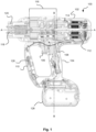
- Fig. 1 shows a side cross-sectional view of a shear wrench tool 100.
- the shear wrench tool 100 is a power tool suitable for tightening a tension control bolt 200 and cooperating nut 202 as shown in Fig. 2 .
- Fig. 2 shows a side view of the bolt 200 and nut 202 for use with the shear wrench tool 100.
- the bolt 200 and nut 202 as shown in Fig. 2 are used to fasten a first workpiece 204 and a second workpiece 206 at a predetermined torque.
- the bolt 200 comprises bolt body portion 208 and a shearable tip 210.
- the nut 202 is threaded on a threaded shaft 212 of the bolt body portion 208.
- the tip 210 shears from the bolt body portion 208 when the shear wrench tool 100 exerts a predetermined torque when tightening the nut 202 on the bolt 200.
- the dimensions of the bolt 200 can be varied to adjust the torque at which the tip 210 shears from the bolt body portion 208.
- the shear wrench tool 100 tightens the nut 202 on the bolt 200 by simultaneously exerting a torque in opposite directions on the bolt 200 and the nut 202. The operation of the shear wrench tool 100 will be discussed in more detail below
- the shear wrench tool 100 comprises a housing 102 which has a clam-shell type construction.
- the housing 102 extends along a first longitudinal axis A-A.
- the housing 102 comprises a primary handle 104 for the user to grip during use.
- the primary handle 104 extends in a direction substantially perpendicular to the first longitudinal axis A-A along a second longitudinal axis B-B.
- a trigger 106 is located in the primary handle 104 and is arranged to actuate a trigger switch 108 when the user squeezes the trigger 106.
- the housing 102 comprises a secondary handle 110 for the user to also grip during use.
- a DC brushless motor 112 is mounted in the housing 102 and is electrically connected to a removeable battery pack 128.
- the battery pack 128 is connected to the housing 102 on the primary handle 104.
- the battery pack 128 is mechanically mounted via an electrical and mechanical connection.
- the battery pack 128 is known and will not be discussed in any further detail.
- a controller 126 is mounted in the housing 102 and the controller 126 is electrically connected to motor 112 and the battery pack 128.
- the controller 126 is configured to issue control signals to the motor 112 to control the speed and direction of the motor 112.
- the controller 126 interacts with control circuitry of the DC brushless motor 112 for controlling operation of the motor 112.
- the controller 126 mounted on a printed circuit board and fastened to the housing 102. It will be appreciated by persons skilled in the art that there is freedom to select an appropriate location of the controller 126 within the shear wrench tool 100.
- the motor 112 comprises an output drive shaft 114.
- the output drive shaft 114 is operatively connected to a transmission 116.
- the transmission 116 in turn is operatively connected to a first socket 118 and a second socket 120. In this way, the transmission 116 transmits a torque provided by the motor 112 to the first and second sockets 118, 120.
- the first socket 118 is engageable with the tip 210 of the bolt 200 and rotates in a first direction when the motor 112 is operated in use.
- the second socket 120 is engageable with the nut 202 and rotates in an opposite direction to the first socket 118 when the motor 112 is operated in use.
- the transmission 116 comprises a plurality of operatively coupled planetary and sun gears in order to generate a high torque at the first and second sockets 118, 120.
- the configuration of a transmission 116 suitable for transferring torque between the motor 112 and the first and second sockets 118, 120 will be apparent to a person skilled in the art; for example a suitable transmission is the transmission 24 described in EP 3 831 532 A1 the contents of which are incorporated herein by reference.
- the transmission 116 can comprise any suitable gearing between the output drive shaft 114 of the motor and the first and second sockets 118, 120 to transmit torque therebetween.
- the torque exerted by the first and second sockets 118, 120 is high. This means that the frictional forces between the first socket 118 and the bolt 200 and the second socket 120 and the nut 202 are sufficiently high to prevent the user from removing the shear wrench tool 100 from the bolt 200 and nut 202. Due to factors including the motor 112 comprising permanent magnets and friction experienced by the gearing of the transmission 116, this means that the user is not able to manually reverse the direction of the first and second sockets 118, 120.
- the user may only release the shear wrench tool from a bolt 200 and a nut 202 by shearing the tip 210 from the bolt body portion 208.
- the user may want to only partly tighten the nut 202 against the bolt 200. That is, the user does not want to always shear the tip 210 from the bolt 200 when tightening the nut 202.
- the user may desire to insert multiple bolts 200 into the first and second workpieces 204, 206 and ensure correct alignment of the workpieces before fully tightening the bolts 200 and nuts 202.
- the user can easily move the first workpiece 204 with respect to the second workpiece 206, including unfastening a nut 202 from a bolt 200 to enable this adjustment, to ensure the correct position of the first and second workpieces 204, 206.
- the shear wrench tool 100 is operable in a pre-shear mode whereby the shear wrench tool 100 fastens the bolt 200 and the nut 202 without shearing the tip 210 from the bolt body portion 208. Operation of the shear wrench tool 100 in the pre-shear mode will now be discussed in further detail with respect to Figs 3 and 4 .
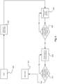
- Fig. 3 shows a schematic drawing of the shear wrench tool 100.
- the controller 126 is connected to a memory 300 for storing operational parameters of the shear wrench tool 100.
- the trigger switch 108 is connected to the controller 126 which is configured to receive a signal from the trigger switch 108 when the trigger 106 is actuated.
- Fig. 4 shows a flow diagram of a first example of the shear wrench tool 100 operating in the pre-shear mode.
- the operation of the shear wrench tool 100 starts.
- the operation of the shear wrench tool 100 is started by the user squeezing the trigger 106.
- the trigger 106 then closes trigger switch 108 and the controller 126 receives the signal from the trigger switch 108.
- the controller 126 then initiates the shear wrench tool 100 to operating in the pre-shear mode as shown in step 402. This means that the controller 126 prevents the shear wrench tool 100 from shearing the tip 210 of the bolt 200 from the bolt body portion 208.
- the controller 126 then issues a control signal to the motor 112 to rotate in a first direction as shown in step 404. As mentioned above, this transmits a torque via the transmission 116 to the first socket 118 and the second socket 120.
- the first and second sockets 118, 120 rotate in first opposing directions for tightening the nut 202 on the bolt 200.
- the controller 126 continues to control the motor 112 to rotate in the first direction. Whilst the motor 112 rotates in the first direction, the controller 126 determines in step 406 whether the motor 112 has rotated in the first direction equal to a predetermined extent.
- the predetermined extent of rotation of the motor 112 in the first direction is a threshold number of motor turns.
- the threshold number of motor turns in the first direction is stored in the memory 300.
- the threshold number of motor turns in the first direction is selectively predetermined depending on the circumstances such as the properties of the bolt 200 and nut 202 to be used, the thickness of the objects 204, 206 being fastened together and the extent of play between the objects 204, 206 which is needed to achieve pre-shear functionality.
- the threshold number of motor turns in the first direction can be changed and thereby selected so that the shear wrench tool 100 will not fully tighten the bolt 200 and nut 202 in the pre-shear mode.
- the tool 100 stores multiple sets of data in the memory 300 associating respective threshold numbers of motor turns with different types of data (such as different types of bolt and nut combinations, thicknesses of objects 204, 206 being fastened and required degrees of play between such objects 204, 206 needed to achieve pre-shear functionality), meaning that a user can select the appropriate threshold number of motor turns based on the required effect.
- different types of data such as different types of bolt and nut combinations, thicknesses of objects 204, 206 being fastened and required degrees of play between such objects 204, 206 needed to achieve pre-shear functionality
- the threshold number of motor turns in the first direction corresponds to a torque which is not great enough to shear the tip 210 from the bolt body portion 208. This means that as the controller 126 keeps the number of motor turns below the threshold number of motor turns in the first direction in the pre-shear mode, the bolt 200 and nut 202 will not be fully tightened.
- step 406 On a negative determination by the controller 126 in step 406, namely that the number of motor turns is below the threshold number of motor turns in the first direction, the controller 126 continues to rotate the motor 112 in the first direction.
- step 406 On a positive determination by the controller 126 in step 406, namely that the number of motor turns is equal to or above the threshold number of motor turns in the first direction, the controller 126 stops the motor 112 rotating in the first direction.
- the controller 126 determines the extent of the rotation of the motor 112 in different ways.
- the controller 126 determines the extent of the motor rotation by counting the number of turns of the motor 112 makes in the pre-shear mode.
- the controller 126 can receive a signal from the motor 112 corresponding to the number of turns that the motor 112 has made.
- the concept of counting motor turns is known and suitable techniques for counting motor turns of the motor 112 of the shear wrench tool 100 will be apparent to persons skilled in the art.
- the controller 126 receives information from the control circuitry of the motor 112 which is indicative of motor turn information. Such information received from the control circuitry of the motor 112 can be directly indicative of motor turn information, whereas in other embodiments the controller 126 derives motor turn information based on the information received from the motor control circuitry.
- the controller 126 issues a control signal to rotate the motor 112 in a second direction as shown in step 408.
- the second direction of the motor 112 is the reverse direction to the first direction. This transmits a torque via the transmission 116 to the first socket 118 and the second socket 120.
- the first and second sockets 118, 120 rotate in second opposing directions.
- the motor 112 does not rotate in the second direction for a sufficient number of turns to remove the nut 202 from the bolt 200. Instead, the motor 112 rotates a predetermined extent in the second direction to release the first and second sockets 118, 120 from the bolt 200 and the nut 202.
- the reverse rotation of the motor 112 and the transmission 116 mean that the frictional forces between the first and second sockets 118, 120 and the bolt 200 and the nut 202 is reduced so that a user can remove the tool 100 from the snugly tightened but unsheared bolt 200 and nut 202.
- the predetermined extent to which the first and second sockets 118, 120 should rotate relative to each other in the reverse direction ranges in some embodiments between 1 and 16 degrees; it will however be appreciated that in other embodiments this range may be different and is dependent on the nature of the cooperating surfaces between the first and second sockets 118, 120 and the nut 202 and the tip 210 of the bolt 200.
- Changes in the shape of such features which are in contact with each other in use changes the extent to which the first and second sockets 118, 120 are required to be rotated relative to each other in order to reduce friction between the first and second sockets 118, 120 and the nut 202 and the tip 210 of the bolt 200 to such an extent that a user can pull the shear wrench tool 100 away from an unsheared bolt 200.
- the first and second sockets 118, 120 will need to be rotated further relative to each other to implement pre-shear functionality compared to if there is a smaller degree of play between such cooperating surfaces of the second socket 120 and the nut 202.
- the controller 126 determines in step 410 whether the motor 112 has rotated by a predetermined extent.
- the predetermined extent of rotation of the motor 112 is a threshold number of motor turns stored in the memory 300.
- the threshold number of motor turns in the second direction is dependent on the nature of the transmission 116, namely the overall gear ratio between the input and output sections of the transmission 116, meaning there is some freedom in the specific number of the threshold number of motor turns selected for implementing step 410 however the threshold number of motor turns selected should be enough to merely release the first and second sockets 118, 120 from the bolt 200 and the nut 202 such that a user can pull the tool 100 from the snugly tightened but unsheared bolt 200 and nut 202. In other words the threshold number of motor turns selected should be enough to cause the first and second sockets 118, 120 to rotate in the reverse direction relative to each other to the aforementioned predetermined extent.
- step 410 On a negative determination by the controller 126 in step 410, namely that the number of motor turns is below the threshold number of motor turns in the second direction, the controller 126 continues to rotate the motor 112 in the second direction.
- step 410 On a positive determination by the controller 126 in step 410, namely that the number of motor turns is equal to or above the threshold number of motor turns in the second direction, the controller 126 stops the motor 112 rotating in the second direction as shown in step 412.
- the shear wrench tool 100 can be removed from the bolt 200 and the nut 202.
- Fig. 5 shows another example of a flow diagram of operation of another shear wrench tool 100 in pre-shear mode.
- Fig. 5 is the same as shown in Fig. 4 except that controller 126 determines that the motor 112 has rotated in the first direction equal to a predetermined extent in a different way.
- step 406 has been replaced with step 500.
- the controller 126 determines whether the user has released the trigger 106 in the pre-shear mode. When the user releases the trigger 106 in the pre-shear mode, the user decides when the bolt 200 and the nut 202 are tight enough. For example, the user can feel or hear when the shear wrench tool 100 has sufficiently tightened the bolt 200 and the nut 202 without shearing the tip 210.
- step 500 On a negative determination by the controller 126 in step 500, namely that the user has not released the trigger 106, the controller 126 continues to rotate the motor 112 in the first direction in step 404.
- step 500 On a positive determination by the controller 126 in step 500, namely that the user has released the trigger 106, the controller 126 stops the motor 112 rotating in the first direction and continues to step 408 as before.
- FIG. 6 shows another example of a flow diagram of operation of another shear wrench tool 100 in pre-shear mode.
- Fig. 6 is the same as shown in Fig. 4 except that controller 126 determines that the motor 112 has rotated in the first direction equal to a required extent in a different way.
- step 406 has been replaced with step 600.
- the controller 126 determines whether the torque of the motor 112 is equal to a predetermined torque threshold.
- the controller 126 continues to control the motor 112 to rotate in the first direction. Whilst the motor 112 rotates in the first direction, the controller 126 determines in step 600 whether the motor 112 is providing a torque equal to a predetermined torque threshold.
- the torque generated by the motor 112 is proportional to the torque provided by the first and second sockets 118, 120 to the nut 202 and bolt 200 wherein the predetermined torque threshold is selected such that the torque output by the tool 100 is below the torque needed to shear the tip 210.
- Tool 100 stores multiple sets of data in the memory 300 associating respective threshold torque values with different types of data (such as different types of bolt and nut combinations, thicknesses of objects 204, 206 being fastened and required degrees of play between such objects 204, 206 needed to achieve pre-shear functionality), meaning that a user can select the appropriate threshold torque value based on the required effect.
- types of data such as different types of bolt and nut combinations, thicknesses of objects 204, 206 being fastened and required degrees of play between such objects 204, 206 needed to achieve pre-shear functionality
- step 600 On a negative determination by the controller 126 in step 600, namely that the torque provided by the motor 112 is below the predetermined torque threshold, the controller 126 continues to rotate the motor 112 in the first direction in step 404.
- step 600 On a positive determination by the controller 126 in step 600, namely that the torque provided at the motor 112 is at least equal to the predetermined torque threshold, the controller 126 stops the motor 112 rotating in the first direction and continues to step 408 as before.
- the controller 126 stops the motor 112 rotating in the first direction and continues to step 408 as before.
- the controller 126 is connected to a torque sensor 302 which is operatively coupled to the output drive shaft 114 of the motor 112. This means that the controller 126 can determine the torque provided by the motor 112 during operation.
- FIG. 7 shows another example of a flow diagram of operation of another shear wrench tool 100 in pre-shear mode.
- Fig. 7 is the same as shown in Fig. 4 except that controller 126 determines that the motor 112 has rotated in the first direction equal to a required extent in a different way.
- step 406 has been replaced with step 700.
- the controller 126 determines whether the load of the motor 112 is equal to a predetermined load threshold.
- the predetermined load threshold corresponds to a load of the motor 112 when the first and second sockets 118, 120 snugly tighten the nut 202 on the bolt 200 but do not shear the tip 210 from the bolt body portion 208.
- the controller 126 determines the load on the motor 112 based on the motor current and/or the motor voltage.
- the load of the motor 112 is proportional to the torque provided by the first and second sockets 118, 120 to the nut 202 and bolt 200 wherein the predetermined load threshold is selected such that the torque output by the tool 100 is below the torque needed to shear the tip 210.
- Tool 100 stores multiple sets of data in the memory 300 associating respective threshold motor load threshold values with different types of data (such as different types of bolt and nut combinations, thicknesses of objects 204, 206 being fastened and required degrees of play between such objects 204, 206 needed to achieve pre-shear functionality), meaning that a user can select the appropriate motor load threshold value based on the required effect.
- types of data such as different types of bolt and nut combinations, thicknesses of objects 204, 206 being fastened and required degrees of play between such objects 204, 206 needed to achieve pre-shear functionality
- step 700 On a negative determination by the controller 126 in step 700, namely that the load of the motor 112 is below the predetermined motor load, the controller 126 continues to rotate the motor 112 in the first direction in step 404.
- step 700 On a positive determination by the controller 126 in step 700, namely that the load of the motor 112 is at least equal to the predetermined motor load, the controller 126 stops the motor 112 rotating in the first direction and continues to step 408 as before.
- the controller 126 stops the motor 112 rotating in the first direction and continues to step 408 as before.
- FIG. 8 illustrates a flow diagram of operation of another shear wrench tool 100.
- Fig. 8 is the same as shown in Fig. 4 except that the shear wrench tool 100 can be selectively operated in either a pre-shear mode or a shear mode. The steps of the pre-shear mode have been previously discussed with reference to Fig 4 .
- the shear mode of the shear wrench tool 100 is a mode of operation whereby the shear wrench tool 100 fastens the bolt 200 and the nut 202 to the extent that it shears the tip 210 from the bolt body portion 208.
- the shear wrench tool 100 comprises a mode selector 304 for manually selecting between the pre-shear mode and the shear mode.
- the mode selector 304 is a slider switch mounted on the housing 102 and is configured to transmit a signal to the controller 126. Accordingly, the controller 126 can determine the selected mode from the position of the mode selector 304.
- the controller 126 determines whether the pre-shear mode is selected as shown in step 800.
- the mode selector 304 is in a first configuration corresponding to the pre-shear mode.
- the mode selector 304 sends a signal to the controller 126 corresponding to the selection of the pre-shear mode.
- the controller 126 in step 800 determines that the pre-shear mode is selected and the controller 126 continues to initiate the pre-shear mode in step 402 as before; wherein step 406 can be replaced with any of steps 500, 600 and 700 as heretofore described.
- the mode selector 304 is in a second configuration corresponding to the shear mode.
- the mode selector 304 sends a signal to the controller 126 corresponding to the selection of the shear mode. Accordingly, the controller 126 in step 800 determines that the shear mode is selected and the controller 126 initiates the shear mode as shown in step 802.
- the controller 126 then issues a control signal to the motor 112 to rotate in the first direction as shown in step 804.
- the motor 112 continues to rotate in the first direction until a user releases the trigger 106 upon manually determining that the tip 210 of the bolt 200 is sheared from the bolt body portion 208 and the controller 126 stops the motor 112 in step 412.
- the mode selector 304 is a button which the user depresses to select the pre-shear mode.
- the controller 126 will default to initiating the shear mode in step 802 unless the mode selector 304 is depressed. This means that the shear wrench tool 100 will default to a normal shear mode unless the user actively selects the pre-shear mode.
- the mode selector 304 is optional and the step 800 as shown in Fig. 8 is optional.
- the controller 126 automatically selects the pre-shear mode or the shear mode without the user actuating a slider switch or depressing a button.
- the controller 126 can automatically power up in a pre-shear mode and the controller 126 can operate in the pre-shear mode until the user releases the trigger 106 for a first time.
- the controller 126 On detection of the user squeezing the trigger 106 again within a predetermined time frame, the controller 126 operates the shear wrench tool 100 in the shear mode. If the user waits longer than the predetermined time frame before pulling the trigger 106 again then the process starts again and the tool will remain in pre-shear mode.
- the pre-shear functionality has been computer controlled, however, it is envisaged that in other embodiments pre-shear functionality can be manually controlled.
- the shear wrench tool 100 in Fig. 1 has a feature which can be manipulated by a user for indicating to the controller 126 whether to run the motor 112 forwards or backwards upon pulling of the trigger 106.
- a feature may be a slide switch which causes the generation of a signal indicative to the controller 126 of whether the motor 112 should run forwards or backwards upon pulling of the trigger 106 depending on the position of the slide switch.
- a button can be provided which when depressed causes the generation of a signal indicative to the controller 126 that the motor 112 should run forwards upon pulling of the trigger 106 and then when depressed again causes the generation of a signal indicative that the motor 112 should run backwards upon pulling of the trigger 106, whereby subsequent pushes of the button indicate to the controller 126 whether to run the motor 112 forwards or backwards upon pulling the trigger 106; the user can thus control the motor 112 to run forwards or backwards by pushing the button.
- the user selects that the motor 112 should run forwards.
- the user then commences a fastening operation in the normal manner firstly by engaging the first and second sockets 118, 120 with the tip 210 of a bolt 200 and a nut 202 and secondly by pulling the trigger 106 of the shear wrench tool 100.
- the user decides when the bolt 200 and the nut 202 are tight enough and releases the trigger 106 to stop the motor 112. For example, the user can feel or hear when the shear wrench tool 100 has sufficiently tightened the bolt 200 and the nut 202 around workpieces 204, 206 without shearing the tip 210.
- the user selects that the motor 112 should run backwards e.g. by using the aforementioned slide switch or button to indicate to the controller 126 that the motor 112 should run in reverse upon pulling of the trigger 106.
- the user then pulls the trigger 106 for driving the first and second sockets 118, 120 in the opposite direction to that in which they were driven during tightening.
- the user pulls the shear wrench tool 100 away from the bolt 200 and nut 202.
- the shear wrench tool 100 may be able to implement computer controlled pre-shear mode functionality and/or manual pre-shear mode functionality in which case a feature is provided which can be manipulated by a user (e.g. a button) for indicating to the controller 126 whether or not manual pre-shear mode functionality is selected.
- a user e.g. a button
- Some other shear wrench tools 100 do not have a feature for indicating to the controller 126 to run the motor 112 forwards or backwards. On the contrary the motor 112 is always caused to run in the same direction.
- the first and second sockets 118, 120 are caused to selectively rotate in a first direction relative to each other and in a second direction relative to each other due to a feature of the transmission which, when in a first position causes the first and second sockets 118, 120 to rotate in a first direction relative to each other and when in a second position causes the first and second sockets 118, 120 to rotate in a second direction relative to each other.
- a slidable feature for manipulation by a user may be provided, which is operatively coupled to said feature of the transmission, to selectively cause the first and second sockets 118, 120 to rotate in the first or second direction relative to each other.
- controller 126 may be implemented in hardware or special purpose circuits, software, logic, or any combination thereof.
- some aspects may be implemented in hardware while other aspects may be implemented in firmware or software which may be executed by the controller 126, microprocessor or other computing device although the disclosure is not limited thereto.
- firmware or software which may be executed by the controller 126, microprocessor or other computing device although the disclosure is not limited thereto. While various aspects of the disclosure may be illustrated and described as block diagrams, flow charts, or using some other pictorial representation, it is well understood that these blocks, apparatus, systems, techniques or methods described herein may be implemented in, as non-limiting examples, hardware, software, firmware, special purpose circuits or logic, general purpose hardware or by the controller 126 or other computing devices or some combination thereof.
- the examples of this disclosure may be implemented by computer software executable by a data processor or by hardware or by a combination of software and hardware.
- the data processing may be provided by means of one or more data processors.
- any blocks of the logic flow as in the Figures may represent program steps, or interconnected logic circuits, blocks and functions, or a combination of program steps and logic circuits, blocks and functions.
- the memory 300 may be of any type suitable to the local technical environment and may be implemented using any suitable data storage technology, such as semiconductor based memory devices, magnetic memory devices and systems, optical memory devices and systems, fixed memory, and removable memory.
- the controller 126 may be of any type suitable to the local technical environment, and may include one or more of general purpose microprocessors, digital signal processors (DSPs) or processors based on multi core processor architecture as non-limiting examples.
- DSPs digital signal processors
- Some examples of the disclosure may be implemented as a chipset, in other words a series of integrated circuits communicating among each other.
- the chipset may comprise microprocessors arranged to run code, application specific integrated circuits (ASICs), or programmable digital signal processors for performing the operations described above.
- ASICs application specific integrated circuits
- programmable digital signal processors for performing the operations described above.
- the motor 112 has been described as being a DC brushless motor and the controller 126 cooperates with the brushless motor (in particular with its control electronics) in order to control the brushless motor and determine motor status information e.g. number of motor turns.
- the motor 112 may be a brushed motor having a motor output shaft driven by a stator and having at least one magnet on the motor output shaft.
- the tool 100 additionally has at least one motor sensor for generating output indicative of motor turn information; such as at least one Hall sensor which cooperates with the at least one magnet on the motor output shaft and which generates output indicative of variations in magnetic flux density as the motor shaft rotates which can be used by the controller 126 to determine motor turn information e.g. number of motor turns. Since the concept of determining motor turn information in the context of brushed and brushless motors is already known there is freedom for a designer to select an appropriate way of determining motor turn information when designing a shear wrench tool 100 which implements the invention described herein.
- at least one motor sensor for generating output indicative of motor turn information; such as at least one Hall sensor which cooperates with the at least one magnet on the motor output shaft and which generates output indicative of variations in magnetic flux density as the motor shaft rotates which can be used by the controller 126 to determine motor turn information e.g. number of motor turns. Since the concept of determining motor turn information in the context of brushed and brushless motors is already known there is freedom for a designer to select
- the motor 112 (whether brushed or brushless) is configured to operate using DC current whereas in mains operated embodiments the motor is configured to operate using AC current.
Abstract
A shear wrench tool comprising: a motor; a transmission operatively connected to the motor;a first socket arranged to engage a tip of a bolt to be sheared; and a second socket arranged to engage a nut threaded on the bolt; wherein the first and second sockets are operatively connected to the transmission and rotate in opposite directions relative to each other when the motor provides a torque to the transmission; and wherein the motor can be driven in both forwards and reverse directions.
Description
- The disclosure relates to a shear wrench tool.
- In some worksites tension control bolts are used to fasten two workpieces together, for example, steel joints in heavy construction. During a fastening operation a nut and a tension control bolt are threadably tightened until a tip shears from the tension control bolt when a predetermined fastening torque is exceeded. When a user commences such a fastening operation with a shear wrench tool the user cannot remove the shear wrench tool from the tension control bolt and nut until the tip has been sheared due to friction occurring between the shear wrench tool and the parts of the tension control bolt and nut which are engaged by the tool. This can be problematic if the user initiates a fastening operation when the workpiece is in the wrong position because the position of the workpiece cannot be adjusted after the tension control bolt is fully tightened.
- According to the present invention there is provided a shear wrench tool according to claim 1. Such a tool can be used to tighten a nut on a tension control bolt without shearing the tip of the bolt and then remove the tool from the nut and bolt combination, whereby a user can install a workpiece in place using a plurality of tension control bolts and check that the workpiece is in the correct position before permanently fixing the workpiece in place. Naturally if the workpiece is not in the correct position the nuts can be loosened on the tension control bolts to enable workpiece adjustment. When the workpiece is in the correct position the user can fix it permanently in place by tightening the nuts on the tension control bolts and shearing the tips of the tension control bolts.
- Optional features of the shear wrench tool are defined in the dependent claims 2 to 14.
- Various aspects and examples of the invention will now be described by way of non-limiting example with reference to the accompanying drawings, in which:
-
Fig. 1 shows a cross-sectional side view of a shear wrench tool according to an example; -
Fig. 2 shows a side view of a bolt and a nut for use with a shear wrench tool according to an example; -
Fig. 3 shows a schematic view of a shear wrench tool according to an example; -
Figs 4 to 8 show flow diagrams of operation of a shear wrench tool according to various examples. -
Fig. 1 shows a side cross-sectional view of ashear wrench tool 100. Theshear wrench tool 100 is a power tool suitable for tightening atension control bolt 200 and cooperatingnut 202 as shown inFig. 2 . -
Fig. 2 shows a side view of thebolt 200 andnut 202 for use with theshear wrench tool 100. Thebolt 200 andnut 202 as shown inFig. 2 are used to fasten afirst workpiece 204 and asecond workpiece 206 at a predetermined torque. Thebolt 200 comprisesbolt body portion 208 and ashearable tip 210. Thenut 202 is threaded on a threadedshaft 212 of thebolt body portion 208. Thetip 210 shears from thebolt body portion 208 when theshear wrench tool 100 exerts a predetermined torque when tightening thenut 202 on thebolt 200. The dimensions of thebolt 200 can be varied to adjust the torque at which thetip 210 shears from thebolt body portion 208. Theshear wrench tool 100 tightens thenut 202 on thebolt 200 by simultaneously exerting a torque in opposite directions on thebolt 200 and thenut 202. The operation of theshear wrench tool 100 will be discussed in more detail below. - The
shear wrench tool 100 comprises ahousing 102 which has a clam-shell type construction. Thehousing 102 extends along a first longitudinal axis A-A. Thehousing 102 comprises aprimary handle 104 for the user to grip during use. Theprimary handle 104 extends in a direction substantially perpendicular to the first longitudinal axis A-A along a second longitudinal axis B-B. Atrigger 106 is located in theprimary handle 104 and is arranged to actuate atrigger switch 108 when the user squeezes thetrigger 106. Thehousing 102 comprises asecondary handle 110 for the user to also grip during use. - A DC
brushless motor 112 is mounted in thehousing 102 and is electrically connected to aremoveable battery pack 128. Thebattery pack 128 is connected to thehousing 102 on theprimary handle 104. Thebattery pack 128 is mechanically mounted via an electrical and mechanical connection. Thebattery pack 128 is known and will not be discussed in any further detail. - A
controller 126 is mounted in thehousing 102 and thecontroller 126 is electrically connected tomotor 112 and thebattery pack 128. Thecontroller 126 is configured to issue control signals to themotor 112 to control the speed and direction of themotor 112. In particular thecontroller 126 interacts with control circuitry of the DCbrushless motor 112 for controlling operation of themotor 112. Thecontroller 126 mounted on a printed circuit board and fastened to thehousing 102. It will be appreciated by persons skilled in the art that there is freedom to select an appropriate location of thecontroller 126 within theshear wrench tool 100. - The
motor 112 comprises anoutput drive shaft 114. Theoutput drive shaft 114 is operatively connected to atransmission 116. Thetransmission 116 in turn is operatively connected to afirst socket 118 and asecond socket 120. In this way, thetransmission 116 transmits a torque provided by themotor 112 to the first andsecond sockets - The
first socket 118 is engageable with thetip 210 of thebolt 200 and rotates in a first direction when themotor 112 is operated in use. Thesecond socket 120 is engageable with thenut 202 and rotates in an opposite direction to thefirst socket 118 when themotor 112 is operated in use. When thetip 210 of thebolt 200 has been sheared from thebolt body portion 208, thetip 210 remains in thefirst socket 118 until it is removed such as by being ejected from thefirst socket 118 by an ejection mechanism of thetool 100. - The
transmission 116 comprises a plurality of operatively coupled planetary and sun gears in order to generate a high torque at the first andsecond sockets transmission 116 suitable for transferring torque between themotor 112 and the first andsecond sockets EP 3 831 532 A1 the contents of which are incorporated herein by reference. Thetransmission 116 can comprise any suitable gearing between theoutput drive shaft 114 of the motor and the first andsecond sockets - When the first and
second sockets bolt 200 and thenut 202 during use, the torque exerted by the first andsecond sockets first socket 118 and thebolt 200 and thesecond socket 120 and thenut 202 are sufficiently high to prevent the user from removing theshear wrench tool 100 from thebolt 200 andnut 202. Due to factors including themotor 112 comprising permanent magnets and friction experienced by the gearing of thetransmission 116, this means that the user is not able to manually reverse the direction of the first andsecond sockets - In previous shear wrench tools after commencing a fastening operation the user may only release the shear wrench tool from a
bolt 200 and anut 202 by shearing thetip 210 from thebolt body portion 208. However, in some circumstances, the user may want to only partly tighten thenut 202 against thebolt 200. That is, the user does not want to always shear thetip 210 from thebolt 200 when tightening thenut 202. For example, the user may desire to insertmultiple bolts 200 into the first andsecond workpieces bolts 200 andnuts 202. By not fully tightening thenuts 202 andbolts 200 the user can easily move thefirst workpiece 204 with respect to thesecond workpiece 206, including unfastening anut 202 from abolt 200 to enable this adjustment, to ensure the correct position of the first andsecond workpieces - In this way, the
shear wrench tool 100 is operable in a pre-shear mode whereby theshear wrench tool 100 fastens thebolt 200 and thenut 202 without shearing thetip 210 from thebolt body portion 208. Operation of theshear wrench tool 100 in the pre-shear mode will now be discussed in further detail with respect toFigs 3 and4 . -
Fig. 3 shows a schematic drawing of theshear wrench tool 100. Thecontroller 126 is connected to amemory 300 for storing operational parameters of theshear wrench tool 100. - The
trigger switch 108 is connected to thecontroller 126 which is configured to receive a signal from thetrigger switch 108 when thetrigger 106 is actuated. Some of the features of theshear wrench tool 100 as shown inFig. 3 are optional and are shown with dotted lines. The optional features will be described in further detail below in subsequent examples. -
Fig. 4 shows a flow diagram of a first example of theshear wrench tool 100 operating in the pre-shear mode. - At
step 400, the operation of theshear wrench tool 100 starts. The operation of theshear wrench tool 100 is started by the user squeezing thetrigger 106. Thetrigger 106 then closestrigger switch 108 and thecontroller 126 receives the signal from thetrigger switch 108. - The
controller 126 then initiates theshear wrench tool 100 to operating in the pre-shear mode as shown instep 402. This means that thecontroller 126 prevents theshear wrench tool 100 from shearing thetip 210 of thebolt 200 from thebolt body portion 208. - The
controller 126 then issues a control signal to themotor 112 to rotate in a first direction as shown instep 404. As mentioned above, this transmits a torque via thetransmission 116 to thefirst socket 118 and thesecond socket 120. The first andsecond sockets nut 202 on thebolt 200. - The
controller 126 continues to control themotor 112 to rotate in the first direction. Whilst themotor 112 rotates in the first direction, thecontroller 126 determines instep 406 whether themotor 112 has rotated in the first direction equal to a predetermined extent. The predetermined extent of rotation of themotor 112 in the first direction is a threshold number of motor turns. The threshold number of motor turns in the first direction is stored in thememory 300. - The threshold number of motor turns in the first direction is selectively predetermined depending on the circumstances such as the properties of the
bolt 200 andnut 202 to be used, the thickness of theobjects objects shear wrench tool 100 will not fully tighten thebolt 200 andnut 202 in the pre-shear mode. In other words thetool 100 stores multiple sets of data in thememory 300 associating respective threshold numbers of motor turns with different types of data (such as different types of bolt and nut combinations, thicknesses ofobjects such objects - The threshold number of motor turns in the first direction corresponds to a torque which is not great enough to shear the
tip 210 from thebolt body portion 208. This means that as thecontroller 126 keeps the number of motor turns below the threshold number of motor turns in the first direction in the pre-shear mode, thebolt 200 andnut 202 will not be fully tightened. - On a negative determination by the
controller 126 instep 406, namely that the number of motor turns is below the threshold number of motor turns in the first direction, thecontroller 126 continues to rotate themotor 112 in the first direction. - On a positive determination by the
controller 126 instep 406, namely that the number of motor turns is equal to or above the threshold number of motor turns in the first direction, thecontroller 126 stops themotor 112 rotating in the first direction. - In
step 406, thecontroller 126 determines the extent of the rotation of themotor 112 in different ways. In the first example shown inFig. 4 , thecontroller 126 determines the extent of the motor rotation by counting the number of turns of themotor 112 makes in the pre-shear mode. Thecontroller 126 can receive a signal from themotor 112 corresponding to the number of turns that themotor 112 has made. The concept of counting motor turns is known and suitable techniques for counting motor turns of themotor 112 of theshear wrench tool 100 will be apparent to persons skilled in the art. Thecontroller 126 receives information from the control circuitry of themotor 112 which is indicative of motor turn information. Such information received from the control circuitry of themotor 112 can be directly indicative of motor turn information, whereas in other embodiments thecontroller 126 derives motor turn information based on the information received from the motor control circuitry. - Once the
controller 126 has stopped themotor 112 in the first direction, thecontroller 126 issues a control signal to rotate themotor 112 in a second direction as shown instep 408. The second direction of themotor 112 is the reverse direction to the first direction. This transmits a torque via thetransmission 116 to thefirst socket 118 and thesecond socket 120. The first andsecond sockets motor 112 does not rotate in the second direction for a sufficient number of turns to remove thenut 202 from thebolt 200. Instead, themotor 112 rotates a predetermined extent in the second direction to release the first andsecond sockets bolt 200 and thenut 202. - Accordingly, the reverse rotation of the
motor 112 and thetransmission 116 mean that the frictional forces between the first andsecond sockets bolt 200 and thenut 202 is reduced so that a user can remove thetool 100 from the snugly tightened butunsheared bolt 200 andnut 202. To enable this the predetermined extent to which the first andsecond sockets second sockets nut 202 and thetip 210 of thebolt 200. Changes in the shape of such features which are in contact with each other in use changes the extent to which the first andsecond sockets second sockets nut 202 and thetip 210 of thebolt 200 to such an extent that a user can pull theshear wrench tool 100 away from anunsheared bolt 200. For example if there is a large degree of play between cooperating surfaces of thesecond socket 120 and thenut 202 then the first andsecond sockets second socket 120 and thenut 202. - Whilst the
motor 112 rotates in the second direction, thecontroller 126 determines instep 410 whether themotor 112 has rotated by a predetermined extent. The predetermined extent of rotation of themotor 112 is a threshold number of motor turns stored in thememory 300. The threshold number of motor turns in the second direction is dependent on the nature of thetransmission 116, namely the overall gear ratio between the input and output sections of thetransmission 116, meaning there is some freedom in the specific number of the threshold number of motor turns selected for implementingstep 410 however the threshold number of motor turns selected should be enough to merely release the first andsecond sockets bolt 200 and thenut 202 such that a user can pull thetool 100 from the snugly tightened butunsheared bolt 200 andnut 202. In other words the threshold number of motor turns selected should be enough to cause the first andsecond sockets - On a negative determination by the
controller 126 instep 410, namely that the number of motor turns is below the threshold number of motor turns in the second direction, thecontroller 126 continues to rotate themotor 112 in the second direction. - On a positive determination by the
controller 126 instep 410, namely that the number of motor turns is equal to or above the threshold number of motor turns in the second direction, thecontroller 126 stops themotor 112 rotating in the second direction as shown instep 412. - Once the
motor 112 has stopped rotating in the second direction, theshear wrench tool 100 can be removed from thebolt 200 and thenut 202. -
Fig. 5 shows another example of a flow diagram of operation of anothershear wrench tool 100 in pre-shear mode.Fig. 5 is the same as shown inFig. 4 except thatcontroller 126 determines that themotor 112 has rotated in the first direction equal to a predetermined extent in a different way. - In this case,
step 406 has been replaced withstep 500. In this step, thecontroller 126 determines whether the user has released thetrigger 106 in the pre-shear mode. When the user releases thetrigger 106 in the pre-shear mode, the user decides when thebolt 200 and thenut 202 are tight enough. For example, the user can feel or hear when theshear wrench tool 100 has sufficiently tightened thebolt 200 and thenut 202 without shearing thetip 210. - On a negative determination by the
controller 126 instep 500, namely that the user has not released thetrigger 106, thecontroller 126 continues to rotate themotor 112 in the first direction instep 404. - On a positive determination by the
controller 126 instep 500, namely that the user has released thetrigger 106, thecontroller 126 stops themotor 112 rotating in the first direction and continues to step 408 as before. - Another example is shown in
Fig. 6 which shows another example of a flow diagram of operation of anothershear wrench tool 100 in pre-shear mode.Fig. 6 is the same as shown inFig. 4 except thatcontroller 126 determines that themotor 112 has rotated in the first direction equal to a required extent in a different way. - In this case,
step 406 has been replaced withstep 600. In this step, thecontroller 126 determines whether the torque of themotor 112 is equal to a predetermined torque threshold. - The
controller 126 continues to control themotor 112 to rotate in the first direction. Whilst themotor 112 rotates in the first direction, thecontroller 126 determines instep 600 whether themotor 112 is providing a torque equal to a predetermined torque threshold. The torque generated by themotor 112 is proportional to the torque provided by the first andsecond sockets nut 202 and bolt 200 wherein the predetermined torque threshold is selected such that the torque output by thetool 100 is below the torque needed to shear thetip 210.Tool 100 stores multiple sets of data in thememory 300 associating respective threshold torque values with different types of data (such as different types of bolt and nut combinations, thicknesses ofobjects such objects - On a negative determination by the
controller 126 instep 600, namely that the torque provided by themotor 112 is below the predetermined torque threshold, thecontroller 126 continues to rotate themotor 112 in the first direction instep 404. - On a positive determination by the
controller 126 instep 600, namely that the torque provided at themotor 112 is at least equal to the predetermined torque threshold, thecontroller 126 stops themotor 112 rotating in the first direction and continues to step 408 as before. It will be appreciated that during fastening of thenut 202 onto thebolt 200 when the workpieces being fastened begin to be squeezed by thenut 202 and bolt 200 the output torque of thetool 100 increases, whereby the torque generated by themotor 212 increases and it is when the torque generated by themotor 212 reaches the threshold torque amount that thetool 100 determines thenut 202 has been snugly tightened onto thebolt 200. - The
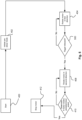
controller 126 is connected to atorque sensor 302 which is operatively coupled to theoutput drive shaft 114 of themotor 112. This means that thecontroller 126 can determine the torque provided by themotor 112 during operation. - Another example is shown in
Fig. 7 which shows another example of a flow diagram of operation of anothershear wrench tool 100 in pre-shear mode.Fig. 7 is the same as shown inFig. 4 except thatcontroller 126 determines that themotor 112 has rotated in the first direction equal to a required extent in a different way. - In this case,
step 406 has been replaced withstep 700. In this step, thecontroller 126 determines whether the load of themotor 112 is equal to a predetermined load threshold. - The predetermined load threshold corresponds to a load of the
motor 112 when the first andsecond sockets nut 202 on thebolt 200 but do not shear thetip 210 from thebolt body portion 208. Thecontroller 126 determines the load on themotor 112 based on the motor current and/or the motor voltage. The load of themotor 112 is proportional to the torque provided by the first andsecond sockets nut 202 and bolt 200 wherein the predetermined load threshold is selected such that the torque output by thetool 100 is below the torque needed to shear thetip 210.Tool 100 stores multiple sets of data in thememory 300 associating respective threshold motor load threshold values with different types of data (such as different types of bolt and nut combinations, thicknesses ofobjects such objects - On a negative determination by the
controller 126 instep 700, namely that the load of themotor 112 is below the predetermined motor load, thecontroller 126 continues to rotate themotor 112 in the first direction instep 404. - On a positive determination by the
controller 126 instep 700, namely that the load of themotor 112 is at least equal to the predetermined motor load, thecontroller 126 stops themotor 112 rotating in the first direction and continues to step 408 as before. It will be appreciated that during fastening of thenut 202 onto thebolt 200 when the workpieces being fastened begin to be squeezed by thenut 202 and bolt 200 the output torque of thetool 100 increases, whereby the power consumed by themotor 212 increases and it is when the load of themotor 212 reaches the threshold load value that thetool 100 determines thenut 202 has been snugly tightened onto thebolt 200. - Another example is shown in
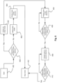
Fig. 8 which illustrates a flow diagram of operation of anothershear wrench tool 100.Fig. 8 is the same as shown inFig. 4 except that theshear wrench tool 100 can be selectively operated in either a pre-shear mode or a shear mode. The steps of the pre-shear mode have been previously discussed with reference toFig 4 . The shear mode of theshear wrench tool 100 is a mode of operation whereby theshear wrench tool 100 fastens thebolt 200 and thenut 202 to the extent that it shears thetip 210 from thebolt body portion 208. - The
shear wrench tool 100 comprises amode selector 304 for manually selecting between the pre-shear mode and the shear mode. Themode selector 304 is a slider switch mounted on thehousing 102 and is configured to transmit a signal to thecontroller 126. Accordingly, thecontroller 126 can determine the selected mode from the position of themode selector 304. - After the
shear wrench tool 100 has been initiated instep 400 by pulling thetrigger 106, thecontroller 126 determines whether the pre-shear mode is selected as shown instep 800. - In a first scenario, the
mode selector 304 is in a first configuration corresponding to the pre-shear mode. Themode selector 304 sends a signal to thecontroller 126 corresponding to the selection of the pre-shear mode. Accordingly, thecontroller 126 instep 800 determines that the pre-shear mode is selected and thecontroller 126 continues to initiate the pre-shear mode instep 402 as before; whereinstep 406 can be replaced with any ofsteps - In a second scenario, the
mode selector 304 is in a second configuration corresponding to the shear mode. Themode selector 304 sends a signal to thecontroller 126 corresponding to the selection of the shear mode. Accordingly, thecontroller 126 instep 800 determines that the shear mode is selected and thecontroller 126 initiates the shear mode as shown instep 802. - The
controller 126 then issues a control signal to themotor 112 to rotate in the first direction as shown instep 804. Themotor 112 continues to rotate in the first direction until a user releases thetrigger 106 upon manually determining that thetip 210 of thebolt 200 is sheared from thebolt body portion 208 and thecontroller 126 stops themotor 112 instep 412. - In another example, the
mode selector 304 is a button which the user depresses to select the pre-shear mode. In this example, thecontroller 126 will default to initiating the shear mode instep 802 unless themode selector 304 is depressed. This means that theshear wrench tool 100 will default to a normal shear mode unless the user actively selects the pre-shear mode. - In another example the
mode selector 304 is optional and thestep 800 as shown inFig. 8 is optional. In this case, thecontroller 126 automatically selects the pre-shear mode or the shear mode without the user actuating a slider switch or depressing a button. For example, thecontroller 126 can automatically power up in a pre-shear mode and thecontroller 126 can operate in the pre-shear mode until the user releases thetrigger 106 for a first time. On detection of the user squeezing thetrigger 106 again within a predetermined time frame, thecontroller 126 operates theshear wrench tool 100 in the shear mode. If the user waits longer than the predetermined time frame before pulling thetrigger 106 again then the process starts again and the tool will remain in pre-shear mode. - In the foregoing embodiments the pre-shear functionality has been computer controlled, however, it is envisaged that in other embodiments pre-shear functionality can be manually controlled. In such an embodiment the
shear wrench tool 100 inFig. 1 has a feature which can be manipulated by a user for indicating to thecontroller 126 whether to run themotor 112 forwards or backwards upon pulling of thetrigger 106. Such a feature may be a slide switch which causes the generation of a signal indicative to thecontroller 126 of whether themotor 112 should run forwards or backwards upon pulling of thetrigger 106 depending on the position of the slide switch. Alternatively a button can be provided which when depressed causes the generation of a signal indicative to thecontroller 126 that themotor 112 should run forwards upon pulling of thetrigger 106 and then when depressed again causes the generation of a signal indicative that themotor 112 should run backwards upon pulling of thetrigger 106, whereby subsequent pushes of the button indicate to thecontroller 126 whether to run themotor 112 forwards or backwards upon pulling thetrigger 106; the user can thus control themotor 112 to run forwards or backwards by pushing the button. - To implement manual pre-shear functionality the user selects that the
motor 112 should run forwards. The user then commences a fastening operation in the normal manner firstly by engaging the first andsecond sockets tip 210 of abolt 200 and anut 202 and secondly by pulling thetrigger 106 of theshear wrench tool 100. The user decides when thebolt 200 and thenut 202 are tight enough and releases thetrigger 106 to stop themotor 112. For example, the user can feel or hear when theshear wrench tool 100 has sufficiently tightened thebolt 200 and thenut 202 aroundworkpieces tip 210. - Subsequently the user selects that the
motor 112 should run backwards e.g. by using the aforementioned slide switch or button to indicate to thecontroller 126 that themotor 112 should run in reverse upon pulling of thetrigger 106. The user then pulls thetrigger 106 for driving the first andsecond sockets shear wrench tool 100 away from thebolt 200 andnut 202. When the first andsecond sockets second sockets nut 202 and thetip 210 of thebolt 200 will have been reduced to such an extent that the user can pull theshear wrench tool 100 away from theunsheared bolt 200. The user then releases thetrigger 106. - The
shear wrench tool 100 may be able to implement computer controlled pre-shear mode functionality and/or manual pre-shear mode functionality in which case a feature is provided which can be manipulated by a user (e.g. a button) for indicating to thecontroller 126 whether or not manual pre-shear mode functionality is selected. - Some other
shear wrench tools 100 do not have a feature for indicating to thecontroller 126 to run themotor 112 forwards or backwards. On the contrary themotor 112 is always caused to run in the same direction. The first andsecond sockets second sockets second sockets second sockets - It will be appreciated that whilst various aspects and examples have heretofore been described the scope of the present invention is not limited thereto and instead extends to encompass all arrangements, and modifications and alterations thereto, which fall within the spirit and scope of the appended claims.
- For instance, whilst illustrative examples have been described as employing software it will be appreciated by persons skilled in the art that the functionality provided by such software may instead be provided by hardware (for example by one or more application specific integrated circuits), or indeed by a mix of hardware and software.
- In general the functionality described in connection with the
controller 126 may be implemented in hardware or special purpose circuits, software, logic, or any combination thereof. For example some aspects may be implemented in hardware while other aspects may be implemented in firmware or software which may be executed by thecontroller 126, microprocessor or other computing device although the disclosure is not limited thereto. While various aspects of the disclosure may be illustrated and described as block diagrams, flow charts, or using some other pictorial representation, it is well understood that these blocks, apparatus, systems, techniques or methods described herein may be implemented in, as non-limiting examples, hardware, software, firmware, special purpose circuits or logic, general purpose hardware or by thecontroller 126 or other computing devices or some combination thereof. - The examples of this disclosure may be implemented by computer software executable by a data processor or by hardware or by a combination of software and hardware. The data processing may be provided by means of one or more data processors. Further in this regard it should be noted that any blocks of the logic flow as in the Figures may represent program steps, or interconnected logic circuits, blocks and functions, or a combination of program steps and logic circuits, blocks and functions.
- The
memory 300 may be of any type suitable to the local technical environment and may be implemented using any suitable data storage technology, such as semiconductor based memory devices, magnetic memory devices and systems, optical memory devices and systems, fixed memory, and removable memory. Also thecontroller 126 may be of any type suitable to the local technical environment, and may include one or more of general purpose microprocessors, digital signal processors (DSPs) or processors based on multi core processor architecture as non-limiting examples. - Some examples of the disclosure may be implemented as a chipset, in other words a series of integrated circuits communicating among each other. The chipset may comprise microprocessors arranged to run code, application specific integrated circuits (ASICs), or programmable digital signal processors for performing the operations described above.
- The
motor 112 has been described as being a DC brushless motor and thecontroller 126 cooperates with the brushless motor (in particular with its control electronics) in order to control the brushless motor and determine motor status information e.g. number of motor turns. In other embodiments however themotor 112 may be a brushed motor having a motor output shaft driven by a stator and having at least one magnet on the motor output shaft. For thecontroller 126 to determine motor turn information of such a brushed motor thetool 100 additionally has at least one motor sensor for generating output indicative of motor turn information; such as at least one Hall sensor which cooperates with the at least one magnet on the motor output shaft and which generates output indicative of variations in magnetic flux density as the motor shaft rotates which can be used by thecontroller 126 to determine motor turn information e.g. number of motor turns. Since the concept of determining motor turn information in the context of brushed and brushless motors is already known there is freedom for a designer to select an appropriate way of determining motor turn information when designing ashear wrench tool 100 which implements the invention described herein. - In battery operated embodiments of the
shear wrench tool 100 the motor 112 (whether brushed or brushless) is configured to operate using DC current whereas in mains operated embodiments the motor is configured to operate using AC current.
Claims (14)
- A shear wrench tool comprising:a motor;a transmission operatively connected to the motor;a first socket arranged to engage a tip of a bolt to be sheared; anda second socket arranged to engage a nut threaded on the bolt;wherein the first and second sockets are operatively connected to the transmission and rotate in opposite directions relative to each other when the motor provides a torque to the transmission; andwherein the motor can be driven in both forwards and reverse directions.
- The shear wrench tool of claim 1 further comprising a user manipulatable portion for selectively causing the motor to operate in a forwards or reverse direction, optionally wherein the user manipulatable portion is a button.
- The shear wrench tool of claim 1 or 2 wherein a user can manually control the extent to which the first and second sockets rotate in a first direction relative to each other in use and the extent to which the first and second sockets rotate in a second direction relative to each other in use.
- The shear wrench tool of claim 1 further comprising a controller for controlling the tool to implement pre-shear mode functionality whereby in use the motor rotates in the forwards direction such that the first and second sockets tighten the bolt and nut on an object without shearing the tip of the bolt and the motor subsequently rotates a predetermined extent in the reverse direction for causing the first and second sockets to rotate in the opposite direction relative to each other.
- The shear wrench tool according to claim 4 wherein the controller causes the motor to reverse the rotational direction from the forwards direction to the reverse direction when the controller determines the motor has rotated in the forwards direction by a predetermined number of motor turns.
- The shear wrench tool according to claim 4 wherein the controller is configured to reverse the motor direction from the forwards direction to the reverse direction when the controller determines that a user releases a trigger switch when the motor is operating in the pre-shear mode.
- The shear wrench tool according to claim 4 wherein a torque sensor is configured to output information indicative of the output torque generated by the motor when the motor rotates in the forwards direction and the controller is configured to reverse the motor direction from the forwards direction to the reverse direction based on the information generated by the torque sensor.
- The shear wrench tool according to claim 4 wherein the controller is configured to monitor the load of the motor, optionally the current consumed by the motor, and is configured to reverse the motor direction from the forwards direction to the reverse direction based on the monitored load of the motor.
- The shear wrench tool according to any of claims 4 to 8 wherein the motor stops rotating in the reverse direction when the motor has rotated in the reverse direction a threshold number of motor turns.
- The shear wrench tool according to any of claims 4 to 8 wherein the motor stops rotating in the reverse direction when the first and second sockets have been rotated relative to each other by a predetermined rotational extent.
- The shear wrench tool of claim 10 wherein the predetermined rotational extent ranges between 1 to 16 degrees.
- The shear wrench tool according to any of claims 4 to 11 wherein the tool can operate in either the pre-shear mode or a shear mode, wherein in the shear mode the motor rotates in the forwards direction in use such that the first socket and the second socket tighten the nut and bolt and shear the tip of the bolt.
- The shear wrench tool according to claim 12 wherein the shear wrench tool comprises a mode selector input configured to enable a user to selectively cause the tool to operate in the pre-shear mode or the shear mode.
- The shear wrench tool according to any of the preceding claims wherein the motor is a brushless DC motor.
Applications Claiming Priority (1)
| Application Number | Priority Date | Filing Date | Title |
|---|---|---|---|
| GBGB2213333.4A GB202213333D0 (en) | 2022-09-13 | 2022-09-13 | Shear wrench tool |
Publications (1)
| Publication Number | Publication Date |
|---|---|
| EP4338889A1 true EP4338889A1 (en) | 2024-03-20 |
Family
ID=83945091
Family Applications (1)
| Application Number | Title | Priority Date | Filing Date |
|---|---|---|---|
| EP23166649.6A Pending EP4338889A1 (en) | 2022-09-13 | 2023-04-04 | Shear wrench tool |
Country Status (3)
| Country | Link |
|---|---|
| US (1) | US20240082991A1 (en) |
| EP (1) | EP4338889A1 (en) |
| GB (1) | GB202213333D0 (en) |
Citations (3)
| Publication number | Priority date | Publication date | Assignee | Title |
|---|---|---|---|---|
| WO2016002293A1 (en) * | 2014-06-30 | 2016-01-07 | 株式会社マキタ | Nut tightening machine |
| JP2016010832A (en) * | 2014-06-30 | 2016-01-21 | 株式会社マキタ | Nut fastening machine |
| EP3831532A1 (en) | 2019-12-06 | 2021-06-09 | Black & Decker Inc. | A shear wrench tool |
-
2022
- 2022-09-13 GB GBGB2213333.4A patent/GB202213333D0/en not_active Ceased
-
2023
- 2023-04-04 EP EP23166649.6A patent/EP4338889A1/en active Pending
- 2023-04-11 US US18/298,566 patent/US20240082991A1/en active Pending
Patent Citations (3)
| Publication number | Priority date | Publication date | Assignee | Title |
|---|---|---|---|---|
| WO2016002293A1 (en) * | 2014-06-30 | 2016-01-07 | 株式会社マキタ | Nut tightening machine |
| JP2016010832A (en) * | 2014-06-30 | 2016-01-21 | 株式会社マキタ | Nut fastening machine |
| EP3831532A1 (en) | 2019-12-06 | 2021-06-09 | Black & Decker Inc. | A shear wrench tool |
Also Published As
| Publication number | Publication date |
|---|---|
| US20240082991A1 (en) | 2024-03-14 |
| GB202213333D0 (en) | 2022-10-26 |
Similar Documents
| Publication | Publication Date | Title |
|---|---|---|
| US7011000B2 (en) | Bolt or nut tightening device having reaction force receiving member | |
| EP1595649A2 (en) | Rotary impact tool | |
| JP5914841B2 (en) | Electric tool | |
| US6971454B2 (en) | Pulsed rotation screw removal and insertion device | |
| US20050247459A1 (en) | Method for operating a disengagable screwdriver, and a disengagable screwdriver | |
| JP2008006560A (en) | Screw part fastener | |
| WO2011074543A1 (en) | Threaded fastener tightening and loosening device | |
| US11130218B2 (en) | Electric quick action wrench with settable torque | |
| WO2018131577A1 (en) | Fastening tool | |
| JP5895211B2 (en) | Electric tool and control device for electric tool | |
| EP4338889A1 (en) | Shear wrench tool | |
| JP5363965B2 (en) | Screw parts tightening device | |
| JP3130851U (en) | Handy type clamping machine with reaction force receiver | |
| EP2708329B1 (en) | Power tool | |
| WO2012108372A1 (en) | Power tool | |
| JP7113264B2 (en) | Electric tool | |
| KR20150001741A (en) | Power wrench | |
| JP5716898B2 (en) | Electric tool | |
| JP5958817B2 (en) | Electric tool | |
| JP2005006384A (en) | Switch for power tool and power tool employing it | |
| JPH04336980A (en) | Power tool | |
| US20240082992A1 (en) | Shear wrench tool | |
| JP7135791B2 (en) | power tools | |
| JP2011148071A (en) | Electric fastening tool | |
| JP2024043261A (en) | Power tools and motor control methods for power tools |
Legal Events
| Date | Code | Title | Description |
|---|---|---|---|
| PUAI | Public reference made under article 153(3) epc to a published international application that has entered the european phase |
Free format text: ORIGINAL CODE: 0009012 |
|
| STAA | Information on the status of an ep patent application or granted ep patent |
Free format text: STATUS: THE APPLICATION HAS BEEN PUBLISHED |
|
| AK | Designated contracting states |
Kind code of ref document: A1 Designated state(s): AL AT BE BG CH CY CZ DE DK EE ES FI FR GB GR HR HU IE IS IT LI LT LU LV MC ME MK MT NL NO PL PT RO RS SE SI SK SM TR |