EP4338807B1 - Vorrichtung zur erfassung einer schwellengeschwindigkeit einer sperrvorrichtung, sperrvorrichtung und verfahren zum blockieren eines drahtelements - Google Patents
Vorrichtung zur erfassung einer schwellengeschwindigkeit einer sperrvorrichtung, sperrvorrichtung und verfahren zum blockieren eines drahtelements Download PDFInfo
- Publication number
- EP4338807B1 EP4338807B1 EP23194746.6A EP23194746A EP4338807B1 EP 4338807 B1 EP4338807 B1 EP 4338807B1 EP 23194746 A EP23194746 A EP 23194746A EP 4338807 B1 EP4338807 B1 EP 4338807B1
- Authority
- EP
- European Patent Office
- Prior art keywords
- rotation
- roller
- axis
- pin
- contact surface
- Prior art date
- Legal status (The legal status is an assumption and is not a legal conclusion. Google has not performed a legal analysis and makes no representation as to the accuracy of the status listed.)
- Active
Links
Images


Classifications
-
- A—HUMAN NECESSITIES
- A62—LIFE-SAVING; FIRE-FIGHTING
- A62B—DEVICES, APPARATUS OR METHODS FOR LIFE-SAVING
- A62B1/00—Devices for lowering persons from buildings or the like
- A62B1/06—Devices for lowering persons from buildings or the like by making use of rope-lowering devices
- A62B1/14—Devices for lowering persons from buildings or the like by making use of rope-lowering devices with brakes sliding on the rope
-
- F—MECHANICAL ENGINEERING; LIGHTING; HEATING; WEAPONS; BLASTING
- F16—ENGINEERING ELEMENTS AND UNITS; GENERAL MEASURES FOR PRODUCING AND MAINTAINING EFFECTIVE FUNCTIONING OF MACHINES OR INSTALLATIONS; THERMAL INSULATION IN GENERAL
- F16D—COUPLINGS FOR TRANSMITTING ROTATION; CLUTCHES; BRAKES
- F16D59/00—Self-acting brakes, e.g. coming into operation at a predetermined speed
- F16D59/02—Self-acting brakes, e.g. coming into operation at a predetermined speed spring-loaded and adapted to be released by mechanical, fluid, or electromagnetic means
-
- A—HUMAN NECESSITIES
- A62—LIFE-SAVING; FIRE-FIGHTING
- A62B—DEVICES, APPARATUS OR METHODS FOR LIFE-SAVING
- A62B1/00—Devices for lowering persons from buildings or the like
- A62B1/06—Devices for lowering persons from buildings or the like by making use of rope-lowering devices
- A62B1/08—Devices for lowering persons from buildings or the like by making use of rope-lowering devices with brake mechanisms for the winches or pulleys
- A62B1/10—Devices for lowering persons from buildings or the like by making use of rope-lowering devices with brake mechanisms for the winches or pulleys mechanically operated
-
- A—HUMAN NECESSITIES
- A62—LIFE-SAVING; FIRE-FIGHTING
- A62B—DEVICES, APPARATUS OR METHODS FOR LIFE-SAVING
- A62B35/00—Safety belts or body harnesses; Similar equipment for limiting displacement of the human body, especially in case of sudden changes of motion
- A62B35/0081—Equipment which can travel along the length of a lifeline, e.g. travelers
-
- A—HUMAN NECESSITIES
- A62—LIFE-SAVING; FIRE-FIGHTING
- A62B—DEVICES, APPARATUS OR METHODS FOR LIFE-SAVING
- A62B35/00—Safety belts or body harnesses; Similar equipment for limiting displacement of the human body, especially in case of sudden changes of motion
- A62B35/0093—Fall arrest reel devices
Definitions
- the invention relates to a device for detecting a threshold speed of a rope blocking device, a blocking device and a method for blocking a rope.
- the person When working at height, to ensure the safety of the person working, it is necessary to connect them to a rope that acts as a lifeline.
- the person is attached to a fall arrest device that runs along the lifeline.
- the fall arrest device has a rotating roller that is configured to turn in one direction or the other depending on whether the person is ascending or descending.
- the vertical speed of the fall arrest device along the lifeline reaches a threshold value, which corresponds to a threshold rotation speed of a roller relative to a plate of the fall arrest device.
- a threshold rotation speed of a roller corresponds to a threshold rotation speed of a roller relative to a plate of the fall arrest device.
- a fall arrest device configuration is marketed by the applicant under the name “ASAP”.
- a fall arrest device configuration is disclosed in the document US 2014/0196985 as well as in the document US 2014/0196989 .
- the documents CN 114 941 667 A , EP 2 958 635 B And EP 2 777 773 A also disclose prior art anti-fall devices.
- the document US 2014/0262611 discloses a configuration where a roller rotates until it reaches a threshold rotational speed. Once the threshold rotational speed is reached, the roller is blocked.
- the roller is mounted to rotate around a rotation shaft.
- Two pins are mounted movably inside the roller and are each actuated by a spring that is configured to bring them back towards the axis of rotation. When the rotational speed of the roller increases, the centrifugal force tends to move the pins outwards so as to come into contact with blockers. Once the pins are in contact with the blockers, the roller can no longer rotate.
- Each of the pins has a contact surface with the blocker that extends over the entire height of the pin and over the entire height of the blocker.
- the blocker and the pin are arranged outside the roller, which corresponds to a relatively bulky device.
- An object of the invention is to provide a detection device configured to detect the rotational speed of a roller of a rope locking device which presents a better compromise between the size of the detection device and the sensitivity of the speed detection.
- a radial distance between the first axis of rotation and the distal part of the weight portion is greater than a radial distance between the first axis of rotation and a proximal portion of the first blocking zone.
- the roller is hollow and the blocker is arranged inside the roller.
- the pin is rotatably mounted about a second rotation shaft between the first pin position and the second pin position, the second rotation shaft being rotatably mounted about the first rotation shaft inside the roller.
- the pin is mounted to rotate about a second rotation shaft between the first pin position and the second pin position.
- a stop is fixedly mounted to the roller, the stop being in contact with the ratchet element when the pin is in the second pin position to reduce the mechanical stress on the second rotation shaft.
- the ratchet element and the second rotation shaft define a functional clearance at least along an arc of a circle of which the first axis of rotation is the center to reduce the mechanical stress on the second rotation shaft.
- the body comprises a first flange and a second flange, the first rotation shaft being fixed to the first flange and to the second flange, the roller being arranged between the first flange and the second flange.
- the blocker is fixedly mounted on the second flange.
- the slide In the first button position, the slide is arranged so as not to obstruct the rotation of the nipple around the first axis of rotation.
- the stud slides along the slide, moving the pin at least to a pin position where the distance between the first axis of rotation and the distal portion of the second contact zone is greater than the distance between the first axis of rotation and the proximal portion of the first contact zone.
- the stud in the second pawn position and in the second button position, the stud is not in contact with the slide.
- the weight portion is arranged inside the roller.
- the weight portion is fixedly mounted relative to the second contact surface.
- the invention also relates to a device for locking a wire element comprising a detection device according to any one of the preceding configurations.
- a locking device is more compact than the configurations of the prior art without degrading the effectiveness in detecting the threshold rotation speed for locking the roller.
- the invention also relates to a method for locking a wire element which makes it possible to efficiently and repeatably detect the threshold rotation speed in order to be able to lock the roller.
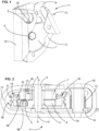
- the Figures 1 to 14 illustrate different views of a locking device 1 for a wire element, preferably a rope.
- the locking device 1 is preferably a fall arrest device.
- the rope locking device comprises a roller 2 mounted to rotate in at least a first direction of rotation around a first rotation shaft 3.
- the first rotation shaft 3 defines a first axis of rotation for the roller 2.
- the locking device 1 defines a path intended for the passage of a rope.
- the path defines a passage crossing of which one wall is formed by the roller 2 so that the sliding of the rope in the locking device causes the rotation of the roller 2.
- the rope locking device is configured to block the rotation of the roller 2 in at least the first direction of rotation when the rotation speed of the roller 2 about the first axis of rotation reaches a threshold value.
- the roller 2 is configured to rotate freely in both directions of rotation at least when the rotation speed is lower than the threshold value.
- the rope locking device comprises a detection device configured to detect the rotation speed of the roller 2 in a direction of rotation.
- the detection device is configured to allow the rotation of the roller 2 when the rotation speed in the first direction of rotation is lower than the threshold speed and to prevent the rotation of the roller 2 when the rotation speed of the roller 2 in the first direction of rotation reaches the threshold speed.
- the detection device detects that the rotation speed in the first direction of rotation corresponds to the threshold speed, the roller 2 locks, which has the effect of locking any rope present in the rope locking device.
- the detection device comprises the roller 2 and the first rotation shaft 3 which defines the first rotation axis of the roller 2.
- the roller 2 is fixed to the first rotation shaft 3.
- the first rotation shaft 3 passes through the roller 2 or is inserted into the roller 2 so that the roller 2 rotates around the first rotation shaft 3.
- the first rotation shaft 3 is fixed to a body.
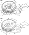
- the detection device comprises at least one pin 4 which is fixed to the roller 2.
- the pin 4 rotates around the first axis of rotation.
- the pin 4 is also mounted to be movable relative to the first axis of rotation so as to be able to move closer to or further away from the first axis of rotation AA.
- the detection device comprises one, two, three or four pins 4.
- the 4 pawns work independently of each other. In the illustrated embodiment, only one pawn 4 is used.
- the detection device comprises a blocker 5.
- the blocker 5 is fixedly mounted on a body.
- the blocker 5 has a first contact surface 5a and the at least one pin 4 has a second contact surface 4a intended to come into contact with the first contact surface 5a to block the rotation of the roller 2.
- Each pin 4 is mounted to move so that the first contact surface 5a moves closer to or further away from the second contact surface 4a.
- the pin 4 moves in a plane perpendicular to the first axis of rotation AA.
- the first contact surface 5a and the second contact surface 4a are crossed by the same plane perpendicular to the first axis of rotation AA.
- the center of gravity of the pin 4 is offset from the first axis of rotation AA so that the rotation of the roller 2 about the first axis of rotation AA causes the rotation of the pin 4 about the first axis of rotation AA and the generation of a centrifugal force which tends to move the second contact surface 4a away from the first axis of rotation.
- the at least one pin 4 is mounted to move relative to the first axis of rotation AA between a first position and a second position.
- the blocker 5 is configured to prevent the rotation of the roller 2 around the first axis of rotation in the first direction of rotation when the first contact surface 5a is in contact with the second contact surface 4a.
- the force generated on the at least one pin 4 is such that the second contact surface 4a comes into contact with the first contact surface 5a which blocks the rotation of the at least one pin 4. least one pin 4 and therefore which blocks the rotation of the roller 2 at least in the first direction of rotation.
- the blocker 5 prevents the rotation of the roller 2 in the first direction of rotation.
- the pin 4 is in the second pin position, it is preferable for the pin 4 to be in contact with the internal side wall of the roller 2.
- the weight portion 4b and the ratchet element 4c are fixedly mounted to each other and they advantageously form part of a monolithic pin.
- the second contact surface 4a of the at least one pin 4 is not in contact with the first contact surface 5a of the blocker 5.
- a first distance between the first axis of rotation AA and a distal part of the second contact area 4a is less than a second distance between the first axis of rotation AA and a proximal part of the first contact surface 5a.
- the second contact surface 4a of the at least one pin 4 is in contact with the first contact surface 5a of the blocker 5. In other words, the first distance is greater than the second distance.
- the detection device defines an annular volume which is arranged between the first axis of rotation AA and the blocker 5. As long as the pin is inside the annular volume, the pin 4 is able to rotate. When the pin 4 projects beyond the annular volume, the rotation of the pin 4 will result in the first contact surface 4a coming into contact with the second contact surface 4a, which will result in the blocking of the roller 2.
- the rotation speed of roller 2 is such that blocker 5 does not oppose the rotation of roller 2 in the first direction of rotation.
- the rotation speed of roller 2 has reached the speed threshold and pin 4 comes to bear against blocker 5 to prevent rotation of roller 2 in the first direction of rotation.
- the roller 2 and the pin 4 can rotate around the first axis of rotation AA without the pin 4 coming into contact with the blocker 5. It is therefore important that there is a significant spacing between the pin 4 and the blocker 5 when the pin 4 and the blocker 5 are arranged radially opposite each other and the roller 2 is stationary or at low speed.
- the second contact surface 4a of the pin 4 is particularly advantageous for the second contact surface 4a of the pin 4 to be biased by a spring in the direction of the first axis of rotation.
- the value of the spacing and the stiffness of the spring make it possible to define the value of the centrifugal force which causes the movement of the pin 4 such that the pin 4 comes to bear on the blocker 5 and therefore this defines the value of the threshold speed.
- the detection device has a spring that is configured to bias the at least one pin 4 so that the second contact surface 4a moves away from the first contact surface 5a.
- the centrifugal force applied to the pin 4 is sufficiently large to oppose the force generated by the spring, which allows the first contact surface 5a to come into contact with the second contact surface 4a and the roller 2 to be blocked.
- the spring opposes the centrifugal force applied to the pin 4, i.e. applies a force directed towards the axis of rotation AA.
- the spring is connected on the one hand to the pin 4 and on the other hand to the roller 2. It is also possible to connect the spring to the pin 4 and to the first rotation shaft 3. In the embodiment illustrated in different figures, the spring is installed in a cavity formed in pin 4, the spring being installed between pin 4 and the bottom of roller 2.
- a stepped pin 4 that is to say a pin which has a weight portion 4b and a pawl element 4c arranged at two different levels along the first axis of rotation AA of the roller.
- the pawl element 4c has the second contact surface 4a and the weight portion 4b is devoid of the second contact surface 4a.
- the weight portion 4b is not intended to come into contact with the blocker 5 to block the rotation of the roller 2.
- the weight portion 4b and the pawl element 4c do not have not the same shape when observed in a direction parallel to the first axis of rotation AA.
- the weight portion 4b and the pawl element 4c are arranged one after the other in a direction parallel to the first axis of rotation AA or substantially parallel to the first axis of rotation AA.
- the distal part of the weight portion 4b is further from the first axis of rotation AA than the distal part of the second contact surface 4a and more generally than the distal part of the pawl element 4c in a radial direction which extends from the first axis of rotation AA.
- the center of gravity of the weight portion 4b is further from the first axis of rotation than the center of gravity of the pawl element 4c. This makes it possible to have an increase in the centrifugal force compared to a pin of constant or substantially constant section over the entire height of the pin 4 (in the direction AA).
- the weight portion 4b has a part which is opposite the ratchet element 4c in an observation along the first axis of rotation AA, it is advantageous to have a opposite equal to at least 50% of the surface of the ratchet element 4c, preferably at least 75%.
- the ratchet element 4c is entirely opposite the weight portion 4b in an observation along the first axis of rotation AA.
- the weight portion 4b has a surface area that is at least 30% greater than the surface area of the pawl element 4c. It is advantageous for the pawl element 4c and the weight portion 4b to be in the form of two arcs of rings. It is preferable for the weight portion 4b to protrude from one or both ends of the pawl element 4c along an arc of a circle whose center corresponds to the first axis of rotation AA. This makes it possible to increase the mass of the pin without increasing the size of the pawl element 4c. This configuration makes it possible to move the center of gravity away compared to a pin 4 comprising only the pawl element 4c.
- the weight portion 4b makes it possible to move the center of gravity away and therefore to increase the centrifugal force for a given threshold rotation speed.
- the stepped configuration of the pin 4 with a weight part 4b which is offset relative to the pawl element 4c makes it possible to improve the compromise between centrifugal force generated and size.
- the weight portion 4b is at a distance from the first axis of rotation AA which is greater than the distance which separates the first axis of rotation AA and the contact zone between the pin 4 and the blocker 5.
- the weight portion 4b when the pin 4 is in the second position with the pawl element 4c resting on the blocker 5, it is advantageous for the weight portion 4b to extend beyond the pawl element 4c over a distance which is equal to at least 10% of the radius between the first axis of rotation AA and the distal part of the contact zone between the blocker 5 and the pawl element 4c. Even more preferably, the weight portion 4b extends beyond the pawl element 4c over a distance which is equal to at least 20%.
- a roller 2 which is hollow and to arrange the pin 4 inside the roller 2. It is possible to form a detection device which better detects the threshold speed without modifying the diameter of the roller 2.
- the blocker 5 is at least partly arranged inside the roller 2 which makes it possible to form a particularly compact detection device without degrading the sensitivity of detection of the rotation speed of the roller 2. It is advantageous for the weight part 4b and/or the ratchet element 4c to be located inside the hollow of the roller 2.
- the blocker 5 When the blocker 5 is installed in the internal volume of the roller 2 which is hollow 2, the blocker 5 does not form an obstacle over the entire height of the internal volume of the roller.
- the height is the dimension parallel to the first axis of rotation AA.
- the blocker 5 leaves a space in the roller 2 so as to allow the rotation of the weight portion 4b above or below the blocker 5.
- a radial distance between the first axis of rotation AA and the distal portion of the weight portion 4b is greater than a radial distance between the first axis of rotation AA and a proximal portion of the first blocking surface 5a.
- the weight portion 4b can then rotate about the first axis of rotation AA and pass above or below the blocker 5 in an observation direction parallel to the first axis of rotation AA when the roller 2 rotates as long as the threshold speed is not reached. Once the threshold speed is reached, the ratchet element 4c comes to bear on the blocker 5 which prevents the rotation of the weight portion 4b and the rotation of the roller 2 in the first direction of rotation AA.
- the weight portion 4b comes into contact with the internal side wall 2a of the roller 2. It is advantageous that when the weight portion 4b comes into contact with the internal side wall 2a of the roller 2, the pawl element 4c is included in a circle whose radius is equal to 2/3 of the radius defined by the internal side wall 2a of the roller 2 and the first axis of rotation.
- the weight portion 4b and the ratchet element 4c are fixedly mounted to each other.
- the distance between the first axis of rotation AA and the distal part of the weight portion 4b is greater than or equal to the distance between the first axis of rotation AA and the proximal part of the first contact surface 5a.
- the proximal part of the pawl element 4c is against the side wall of the roller 2 defining a passage hole for the first rotation shaft 3. It is then advantageous for the distance between the distal part of the pawl element 4c and the first axis of rotation AA to be less than equal to 2/3 of the radius between the first axis of rotation AA and the distal part of the weight portion 4b. This configuration makes it possible to improve the ratio between the speed detection sensitivity and the compactness of the detection device.
- the distal portion of the ratchet element 4c is the portion of the ratchet element 4c furthest from the first axis of rotation.
- the distal portion of the weight portion 4b is the portion of the weight portion 4b furthest from the first axis of rotation.
- the proximal portions are the portions closest to the first axis of rotation AA.
- the comparison of the distances between the distal portions of the ratchet element 4c and the weight portion 4b are carried out for the same radius. The same applies to the comparison between the proximal portions or between the proximal and distal portions.
- the weight portion 4b extends radially beyond the distal part of the ratchet element 4c and it also extends circumferentially as illustrated in the various figures.
- the weight portion 4b extends from each of the two circumferential ends of the ratchet element 4c.
- the ratchet element 4c is located between the projecting part of the weight portion 4b and the first axis of rotation AA.
- the weight portion 4b represents at least 20% of the mass of the pin 4. Even more preferably, the weight portion represents at least 33% of the mass of the pin 4.
- the weight portion 4b and the pawl element 4c are separated by a plane perpendicular to the first axis of rotation AA and which passes through the end of the first contact surface 5a and the second contact zone 4a.
- the mass of the weight portion corresponds to the mass of the pin located on the side of the plane containing the weight portion while the mass of the pawl element 4c corresponds to the mass of the rest of the pin 4 and which is located on the other side of the plane.
- the radius between the first axis of rotation AA and the distal part of the first contact surface 5a is less than or equal to 75% of the radius between the first axis of rotation and the distal part of the weight portion 4b.
- the radius between the first axis of rotation and the first contact zone 5b is less than or equal to 75% of the radius of the internal side wall 2a of the roller 2 when the roller 2 is hollow and receives the blocker 5 as well as the pin 4.
- a hollow roller 2 is particularly advantageous because it improves the compactness of the structure.
- a plane perpendicular to the first axis of rotation AA passes through the ratchet element 4c, the blocker 5 and the groove 2b of the roller 2 which is to receive the rope.
- Improving the compactness of the detection device without degrading the sensitivity of detecting the rotational speed of the roller 2 makes it possible to reduce the diameter of the roller 2.
- the rotational speed of the roller 2 and therefore the effect on the centrifugal force are increased.
- decomposing the pin 4 into a weight portion 4b and a pawl element 4c which are arranged one after the other in a direction parallel to the first axis of rotation makes it possible to reduce the diameter of the roller 2 without reducing the detection sensitivity because it becomes possible to increase the rotational speed of the roller 2 for a given linear rope speed.
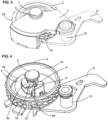
- This configuration is particularly advantageous because, as illustrated in Figures 1 to 14 , the detection device 1 of the rotation speed of the roller 2 is entirely or almost entirely installed inside the roller 2.
- the roller 2 is arranged between a first plate 6 and a second plate 7 of the body.
- the first rotation shaft 3 is fixed to the first plate 6 and to the second plate 7.
- the roller 2 rotates around the first rotation shaft 3 in the body and more precisely between the plates 6 and 7 which are fixed.
- the roller 2 is a blind part with the exception of the hole for the passage of the first rotation shaft 3.
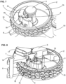
- the pin 4 is fixed to the roller 2 to follow the rotation of the roller 2 around the first axis of rotation AA. It is advantageous for the pin 4 to be mounted so as to be rotatable between the first position and the second position, preferably around a second rotation shaft 8.
- the second rotation shaft 8 is fixed to the roller 2 so that the second rotation shaft 8 rotates around the first rotation shaft 3.
- the pin 4 is fixed to the second rotation shaft 8 so that the pin 4 rotates around the first rotation shaft 3 and rotates around the second rotation shaft 8.
- the pin 4 comes to bear on a stop 9 of the roller 2 which is offset from the second rotation shaft 8.
- the pin 4 has a third contact zone 4d which bears on a fourth contact zone 9a formed by the stop 9 when the pin is in the second pin position, this makes it possible to reduce the mechanical stress on the second rotation shaft 8.
- the stop 9 of the roller 2 exerts a force on the pin 4 and the pin 4 exerts a force on the blocker 5 to block the rotation of the roller 2 in the first direction of rotation without excessively stressing the second rotation shaft 8.
- the blocking of the stop 9 causes the blocking of the roller 2.
- the stop 9 of the roller 2 is fixedly mounted relative to the roller 2.
- the ratchet element 4c is on the one hand in abutment against the stop 9 and on the other hand in abutment against the blocker 5. In the position blocking the rotation of the roller 2, the ratchet element 4c is located between the stop 9 and the blocker 5.
- This configuration makes it possible to reduce the forces applied to the second rotation shaft 8.
- the third contact zone 4d and the fourth contact zone are flat surfaces, they form a first plane which includes the first axis of rotation, as illustrated in the figures 9 to 14 .
- the support is tangential, which limits the stress on the second rotation shaft. It is also possible to have textured contact zones, for example notched or saw-toothed, to reduce or avoid the appearance of a radially extending force which stresses the second rotation shaft 8.
- the pin 4, more preferably the ratchet element 4c, and the second rotation shaft 8 to define a functional clearance in a direction perpendicular to the axis AA representing the axis of rotation of the roller 2.
- the functional clearance extends at least along an arc of a circle whose radius extends from the axis of rotation AA of the roller 2 and which passes through the second rotation shaft 8.
- the arc of a circle has the axis of rotation AA as its center.
- the pin 4 rests against the peripheral side wall of the roller 2 as illustrated in figures 12 And 14 .
- the first contact surface 5a and the second contact area 4a define a second plane parallel to the first axis of rotation AA.
- the first plane intersects the second plane, the contact between the third contact area 4d and the fourth contact area 9a being separated from the intersection between the first plane and the second plane by the first axis of rotation AA in an observation along the first axis of rotation AA.
- a stop 9 is particularly advantageous in association with a stepped pin 4, but it is also possible to have a stop 9 which blocks the rotation of a roller 2 with a pin according to one of the configurations of the prior art, in particular a configuration where the section of the pin 4 is constant or substantially constant over the entire height of the pin.
- the third contact zone 4d is predominantly or exclusively formed by the ratchet element 4c.
- the third contact zone 4d does not extend beyond the radius defined by the distal portion between the ratchet element 4c and the axis of rotation of the roller 2.
- the third contact area 4d is formed in the pawl element 4c as well as in the weight portion 4b. It is advantageous that the third contact area 4d is formed by one face of the weight portion and preferably at a greater distance than the contact area between the stop and the pawl element 4c.
- the second rotation shaft 8 is arranged at a radius from the first rotation axis AA which is less than the radius of the second contact surface 4a when the pin 4 is in the second pin position.
- the first plate 6 and the second plate 7 of the body are fixed to each other by means of a third rotation shaft 10 which is also fixed on a support 11.
- the third rotation shaft 10 and the first rotation shaft 3 are fixed together so as to form a single-piece assembly with the first plate 6 and the second plate 7.
- the single-piece assembly is mounted to move relative to the support 11 and mounted to rotate around the third rotation shaft 10.
- the first rotation shaft 3 is mounted to pivot around the third rotation shaft 10.
- the single-piece assembly pivots relative to the support 11 so as to define an open position which allows the introduction or removal of a rope in the support 11 of the rope locking device, here of the fall arrest device.
- the support 11 has a U-shaped zone 12 which defines a ring intended to receive a rope.
- the ring opens or closes by means of the single-piece assembly which is movable and in particular by means of the roller 2 which moves relative to the support 11.
- the one-piece assembly is biased by means of a second spring 13 so that the one-piece assembly is by default, that is to say in the absence of external bias, in the position which keeps the rope inside the fall arrest device and more precisely inside the U-shaped zone 12.
- the spring biases the roller towards the U-shaped zone which is intended to press the rope against the U-shaped zone to have significant contact between the rope and the roller 2 when the blocking device moves relative to the rope.
- the roller 2 has a groove 2b which is textured, i.e. a non-smooth groove.
- the groove 2b may be provided with pins 2c or grooves so as to increase the friction between the roller 2 and the rope.
- the second plate 7 defines the blocker 5 and is inserted into the hollow of the roller 2.
- the second plate 7 makes it possible to block the rotation of the roller 2.
- the fixing of the second plate 7 with the first plate 6 by means of the first rotation shaft 3 and the third rotation shaft 10 makes it possible to form a particularly effective blocker 5.
- the first plate 6 is fixed to the second plate 7 by means of a rod 14.
- the second plate 7 closes the cavity defined in the roller 2. It is preferable that the speed detection device is provided with a seal 15 of annular section which connects the roller 2 and the second plate 7. It is advantageous that the internal side wall 2a of the roller 2 has a groove 16 which extends circularly. The seal 15 is inserted into the groove 16 so as to provide sealing. The seal 15 which connects the second plate 7 with the roller 2 in association with a roller 2 which is blind makes it possible to form a substantially sealed space which makes it possible to improve the service life of the detection device.
- a button 17 is fixed to the body and preferably to the second plate 7 and is mounted to be movable relative to the second plate 7.
- the button 17 is movable between a first button position and a second button position.
- the button 17 is mounted to be movable relative to the first axis of rotation AA. In the first button position, the button 17 does not interact with the pin 4 which operates as described above.
- the button 17 In the second button position, the button 17 causes the roller 2 to be blocked when the roller 2 rotates in the first direction of rotation.
- the pin 4 is provided with a stud 18. It is advantageous for the stud not to be opposite the second locking zone 4a in a plane perpendicular to the first axis of rotation AA.
- the stud 18 can be mounted projecting from the pawl element 4c or from the weight portion 4b in a direction parallel to the first axis of rotation AA.
- the stud 18 is preferably fixedly mounted on the pin 4. The stud 18 rotates about the first axis of rotation 3 when the roller 2 rotates about the first axis of rotation 3. The stud 18 moves between a first stud position and a second stud position.
- the stud 18 rotates about the first axis of rotation AA at a distance from the first axis of rotation AA which is greater than or equal to a first value.
- the first value corresponds to the minimum distance between the first axis of rotation AA and the stud 18 when the pin 4 is in the first pin position, for example the roller 2 is stationary.
- the stud 18 is spaced from the first axis of rotation by a second value greater than the first value.
- the annular volume has a maximum radius which corresponds to the second value.
- the button 17 defines a slide 19.
- the slide 19 In the first position of the button 17, the slide 19 is arranged so as not to come into contact with the stud 18, it does not form an obstacle to the rotation of the stud 18.
- the stud 18 rotates in a plane which is perpendicular to the first axis of rotation AA.
- the slide 19 In the first position of the button, the slide 19 is arranged outside the plane of rotation of the stud 18 and/or at a distance from the axis of rotation AA which is less than the first value or which is greater than the second value, for example greater than the radius of the roller 2.
- the slide 19 is arranged outside the positions which the stud 18 can take when the roller rotates.
- the slide 19 is arranged to form an obstacle to the movement of the stud 18.
- the slide 19 is located in the plane of rotation of the stud 18, i.e. in a plane perpendicular to the first axis of rotation AA and which passes through the stud 18.
- the slide 19 forms an obstacle which extends from the first value to a third value greater than the first value.
- the third value can be the second value which corresponds to the pin in the second pin position.
- the third value corresponds to the pin 4 in a position such that the distance between the first axis of rotation AA and the distal part of the second contact zone 4a is greater than the distance between the first axis of rotation AA and the proximal part of the first contact zone 5a.
- the ratchet element 4c is far enough from the first axis of rotation AA for the ratchet element 4c to come into contact with the blocker 5 which will cause the roller 2 to be blocked.
- the slide 19 is not in contact with the stud 18 so as to prevent the slide 19 and the stud 18 from taking up the locking forces of the roller 2.
- the pin 4 When the stud 18 is in the first stud position, the pin 4 is in the first pin position. When the stud 18 is in the second stud position, the pin 4 is in the second pin position.
- the stud 18 is fixedly mounted relative to the second contact area 4a.
- the slide 19 moves only in a plane perpendicular to the first axis of rotation AA.
- the button 17 is mounted to move so as to move closer to or further away from the first rotation shaft 3 between the first button position and the second button position.
- the movement of the pin from the first position to the second position is independent of the rotation speed of roller 2.
- the locking of roller 2 is obtained at the latest when the roller has completed a complete revolution.
- Such a button is particularly advantageous because it is simple to produce while being very effective.
- the button and the stud are presented in association with a stepped pin, it is possible to use another pin configuration.
- the stud 18 is not opposite the second contact zone 4a in a plane which is perpendicular to the first axis of rotation AA.
- the button 17 passes through the second plate 7 so that the button 17 defines a slide 19 for the stud 18 which is separated from the actuation zone of the button by the second plate 7.
- the stud 18 slides along the slide 19.
- the stud 18 rotates about the first axis of rotation AA and the stud 18 does not come into contact with the slide 19.
- the stud 18 moves from the first stud 18 position to the second stud 18 position without the stud 18 coming into contact with the slide 19.
- the pin 4 comes into contact with the blocker 5 which blocks the roller 2 without the stud 18 coming into contact with the slide 19.
- the slide 19 intersects the path of the stud 18 when the roller 2 rotates in the first direction of rotation.
- the stud 18 rotates about the first axis of rotation and slides along the slide 19, which causes the stud 18 to move from the first stud position to the second pin position.
- the ratchet element 4c is in contact with the blocker 5 which completes moving the pin 4 into the second pin position.
- the rotation of the roller 2 causes the first contact surface 5a to be in contact with the second contact surface 4a which has the effect of blocking the roller 2.
- the button 17 defines a slide 19 which intercepts the trajectory of the stud 18 which shifts the stud 18 so as to move the pin 4 into the second pin position and thus achieve the locking of the roller 2 independently of the rotation speed of the roller 2.
- the button 17 moves from the first pin position to the second pin position which makes it possible to lock the roller 2 independently of the rotation speed of the roller 2.
- This solution is particularly advantageous because the same pin 4 is used to block roller 2 either when the rotation speed of roller 3 reaches the threshold speed, or when roller 2 makes a turn when button 17 is moved to a position for blocking roller 2.
- buttons 17 are mounted to be able to rotate in order to move the slide 19.
- the configuration illustrated in the Figures 1 to 14 is advantageous because it has a reduced number of parts which reduces the risk of failure rate.
- the device for detecting the rotation speed of the roller is advantageously part of a fall arrest device.
- the fall arrest device may comprise a rope installed in the support in contact with the roller 2.
- the fall arrest device is configured to prevent the fall arrest device from traveling along the rope at a linear speed that is greater than a threshold speed.
- the rope being in contact with the roller, the running speed between the rope and the fall arrest device corresponds to a rotation speed of the roller.
- the wire element is circulated in the blocking device, which causes the roller to rotate. When the rotation speed of the roller 2 reaches the threshold rotation speed, the roller 2 is blocked.
- the roller 2 is configured to cooperate with a rope of circular section, but it is also possible to provide a roller intended to cooperate with a strap whose section is square or rectangular.
- the detection device is particularly suitable for use in a device for blocking a wire element, in particular a rope, but it is also possible to provide for its use in an automatic winder.
Landscapes
- Health & Medical Sciences (AREA)
- General Health & Medical Sciences (AREA)
- Business, Economics & Management (AREA)
- Emergency Management (AREA)
- Engineering & Computer Science (AREA)
- General Engineering & Computer Science (AREA)
- Mechanical Engineering (AREA)
- Physics & Mathematics (AREA)
- Electromagnetism (AREA)
- One-Way And Automatic Clutches, And Combinations Of Different Clutches (AREA)
- Filamentary Materials, Packages, And Safety Devices Therefor (AREA)
- Maintenance And Inspection Apparatuses For Elevators (AREA)
- Clamps And Clips (AREA)
- Transmission Devices (AREA)
- Force Measurement Appropriate To Specific Purposes (AREA)
- Wire Processing (AREA)
Claims (13)
- Detektionsvorrichtung, die dazu konfiguriert ist, die Drehgeschwindigkeit einer Rolle (2) einer Sperrvorrichtung (1) für ein Seilelement zu erfassen, umfassend:- einen Körper (6,7);- eine erste Drehwelle (3), die am Körper (6,7) befestigt ist;- eine Rolle (2), die um die erste Drehwelle (3) drehbar montiert ist, wobei die erste Drehwelle (3) eine erste Drehachse (AA) für die Rolle (2) definiert;- einen Blockierer (5), der am Körper (6, 7) befestigt ist und eine erste Kontaktfläche (5a) aufweist;- mindestens einen Zapfen (4), der derart an der Rolle (2) befestigt ist, dass er sich in einem ringförmigen Volumen, das zwischen der ersten Drehachse (AA) und dem Blockierer (5) angeordnet ist, um die erste Drehachse (AA) dreht, wobei der mindestens eine Zapfen (4) eine zweite Kontaktfläche (4a) aufweist, der mindestens eine Zapfen (4) in Bezug auf die erste Drehachse (AA) zwischen einer ersten Zapfenposition, in welcher ein erster Abstand zwischen der ersten Drehachse (AA) und einem distalen Teil des zweiten Kontaktbereichs (4a) kleiner ist als ein zweiter Abstand zwischen der ersten Drehachse (AA) und einem proximalen Teil der ersten Kontaktfläche (5a), und einer zweiten Zapfenposition, in welcher der erste Abstand größer ist als der zweite Abstand, beweglich montiert ist, wobei die Drehung der Rolle (2) eine Zentrifugalkraft erzeugt, die die zweite Kontaktfläche (4a) von der ersten Drehachse (AA) entfernt, um den Wert des ersten Abstands so zu erhöhen, dass die zweite Kontaktfläche (4a) mit der ersten Kontaktfläche (5a) in Kontakt ist, wenn die Drehgeschwindigkeit der Rolle (2) eine Schwellendrehgeschwindigkeit übersteigt, wobei der Blockierer (5) eine Drehrichtung der Rolle (2) sperrt, wenn die erste Kontaktfläche (5a) mit der zweiten Kontaktfläche (4a) in Kontakt ist;wobei die Detektionsvorrichtung dadurch gekennzeichnet ist, dass der Zapfen (4) einen Fliehgewichtsabschnitt (4b) und ein Klinkenelement (4c) aufweist, die in einer Richtung parallel zur ersten Drehachse (AA) nacheinander angeordnet sind, wobei das Klinkenelement (4c) die zweite Kontaktfläche (4a) umfasst;dass der Fliehgewichtsabschnitt (4b) in der zweiten Zapfenposition nicht mit dem Blockierer (5) in Kontakt ist; unddass ein distaler Teil des Fliehgewichtsabschnitts (4b) entlang der ersten Drehachse (AA) gesehen weiter von der ersten Drehachse (AA) entfernt ist als ein distaler Teil der zweiten Kontaktfläche (4a).
- Detektionsvorrichtung nach Anspruch 1, wobei ein radialer Abstand zwischen der ersten Drehachse (AA) und dem distalen Teil des Fliehgewichtsabschnitts (4b) in der ersten Zapfenposition größer ist als ein radialer Abstand zwischen der ersten Drehachse (AA) und einem proximalen Teil der ersten Blockierfläche (5a).
- Detektionsvorrichtung nach einem der Ansprüche 1 und 2, wobei die Rolle (2) hohl ist und der Blockierer (5) im Inneren der Rolle (2) angeordnet ist.
- Detektionsvorrichtung nach Anspruch 3, wobei der Zapfen (4) zwischen der ersten Zapfenposition und der zweiten Zapfenposition um eine zweite Drehwelle (8) drehbar montiert ist, wobei die zweite Drehwelle (8) an der Rolle befestigt ist und im Inneren der Rolle (2) um die erste Drehwelle (3) drehbar montiert ist.
- Detektionsvorrichtung nach einem der Ansprüche 3 und 4, wobei der Fliehgewichtsabschnitt (4b) im Inneren der Rolle (2) angeordnet ist.
- Detektionsvorrichtung nach einem der Ansprüche 1 bis 5, wobei der Zapfen (4) zwischen der ersten Zapfenposition und der zweiten Zapfenposition um eine zweite Drehwelle (8) drehbar montiert ist, wobei ein Anschlag (9) fest an der Rolle (2) angebracht ist, wobei der Anschlag (9) mit dem Klinkenelement (4c) in Kontakt ist, wenn der Zapfen sich in der zweiten Zapfenposition befindet, um die mechanische Beanspruchung der zweiten Drehwelle (8) zu reduzieren.
- Detektionsvorrichtung nach Anspruch 6, wobei das Klinkenelement (4c) und die zweite Drehwelle (8) mindestens entlang eines Kreisbogens, dessen Mittelpunkt die erste Drehachse (AA) ist, ein Funktionsspiel definieren, um die mechanische Beanspruchung der zweiten Drehwelle (8) zu reduzieren.
- Detektionsvorrichtung nach einem der Ansprüche 1 bis 7, wobei der Körper einen ersten Flansch (6) und einen zweiten Flansch (7) umfasst, wobei die erste Drehwelle (3) am ersten Flansch (6) und am zweiten Flansch (7) befestigt ist, die Rolle (2) zwischen dem ersten Flansch (6) und dem zweiten Flansch (7) angeordnet ist, und wobei der Blockierer (5) fest am zweiten Flansch (7) angebracht ist.
- Detektionsvorrichtung nach einem der Ansprüche 1 bis 8, umfassend :- einen Stift (18), der in einer Richtung parallel zur ersten Drehachse (AA) vom Zapfen (4) vorspringt;einen Knopf (17), der am Körper (6, 7) befestigt ist und zwischen einer ersten Knopfposition und einer zweiten Knopfposition beweglich montiert ist, wobei der Knopf (17) eine Gleitffläche (19) aufweist; undwobei die Gleitffläche (19) in der ersten Knopfposition derart angeordnet ist, dass sie kein Hindernis für die Drehung des Stifts (18) um die erste Drehachse (AA) bildet; undwobei in der zweiten Knopfposition der Stift (18) bei einer Umdrehung der Rolle (2) entlang der Gleitffläche (19) gleitet und den Zapfen (4) dabei mindestens in eine Zapfenposition bewegt, in welcher der Abstand zwischen der ersten Drehachse (AA) und dem distalen Teil der zweiten Kontaktfläche (4a) größer ist als der Abstand zwischen der ersten Drehachse (AA) und dem proximalen Teil der ersten Kontaktfläche (5a).
- Detektionsvorrichtung nach Anspruch 9, wobei der Stift (18) in der zweiten Zapfenposition und in der zweiten Knopfposition nicht mit der Gleitffläche (19) in Kontakt ist.
- Detektionsvorrichtung nach einem der Ansprüche 1 bis 10, wobei der Fliehgewichtsabschnitt (4b) in Bezug auf die zweite Kontaktfläche (4a) fest angebracht ist.
- Sperrvorrichtung für ein Seilelement, umfassend eine Detektionsvorrichtung nach einem der vorherigen Ansprüche.
- Verfahren zum Blockieren eines Seilelements, umfassend die folgenden Schritte:- Bereitstellen einer Sperrvorrichtung nach Anspruch 12 und eines Seilelements, das in der Sperrvorrichtung mit der Rolle (2) in Kontakt montiert ist;- Laufenlassen des Seilelements in der Sperrvorrichtung, sodass die Rolle (2) bis zu einer Schwellendrehzahl gedreht wird, um die Rolle (2) zu blockieren und das Seilelement in der Sperrvorrichtung (1) zu blockieren.
Applications Claiming Priority (1)
| Application Number | Priority Date | Filing Date | Title |
|---|---|---|---|
| FR2209400A FR3139726B1 (fr) | 2022-09-19 | 2022-09-19 | Dispositif de détection d’une vitesse seuil d’un dispositif de blocage, dispositif de blocage et procédé de blocage d’un élément filaire |
Publications (2)
| Publication Number | Publication Date |
|---|---|
| EP4338807A1 EP4338807A1 (de) | 2024-03-20 |
| EP4338807B1 true EP4338807B1 (de) | 2025-03-19 |
Family
ID=84053262
Family Applications (1)
| Application Number | Title | Priority Date | Filing Date |
|---|---|---|---|
| EP23194746.6A Active EP4338807B1 (de) | 2022-09-19 | 2023-08-31 | Vorrichtung zur erfassung einer schwellengeschwindigkeit einer sperrvorrichtung, sperrvorrichtung und verfahren zum blockieren eines drahtelements |
Country Status (5)
| Country | Link |
|---|---|
| US (1) | US20240093736A1 (de) |
| EP (1) | EP4338807B1 (de) |
| CN (1) | CN222318978U (de) |
| ES (1) | ES3024460T3 (de) |
| FR (1) | FR3139726B1 (de) |
Family Cites Families (6)
| Publication number | Priority date | Publication date | Assignee | Title |
|---|---|---|---|---|
| FR3000900B1 (fr) | 2013-01-15 | 2015-02-27 | Zedel | Appareil de securite antichute sur corde avec fonction bloqueur |
| FR3000899B1 (fr) | 2013-01-15 | 2015-06-26 | Zedel | Appareil de securite antichute et blocage sur corde |
| GB201303153D0 (en) * | 2013-02-22 | 2013-04-10 | Capital Safety Group Northern Europ Ltd | Fall Arrest Device |
| US9623269B2 (en) | 2013-03-14 | 2017-04-18 | Black Diamond Equipment, Ltd. | Systems for assisted braking belay with a cam-clutch mechanism |
| EP2777773A3 (de) * | 2013-03-14 | 2017-01-25 | Black Diamond Equipment AG | Bremssysteme für das assistierte Abseilen mit einem Nocken-Kupplungsmechanismus |
| CN114941667B (zh) * | 2022-06-29 | 2025-11-14 | 青岛亿和海丽安防科技有限公司 | 一种自动绳索止坠器 |
-
2022
- 2022-09-19 FR FR2209400A patent/FR3139726B1/fr active Active
-
2023
- 2023-08-31 ES ES23194746T patent/ES3024460T3/es active Active
- 2023-08-31 EP EP23194746.6A patent/EP4338807B1/de active Active
- 2023-09-15 US US18/369,051 patent/US20240093736A1/en active Pending
- 2023-09-18 CN CN202322537193.1U patent/CN222318978U/zh active Active
Also Published As
| Publication number | Publication date |
|---|---|
| ES3024460T3 (en) | 2025-06-04 |
| CN222318978U (zh) | 2025-01-07 |
| US20240093736A1 (en) | 2024-03-21 |
| EP4338807A1 (de) | 2024-03-20 |
| FR3139726A1 (fr) | 2024-03-22 |
| FR3139726B1 (fr) | 2025-04-11 |
Similar Documents
| Publication | Publication Date | Title |
|---|---|---|
| EP0743053B1 (de) | Sicherheits- und Kontrollvorrichtung der Verriegelung einer Radnabe, insbesondere für Rollstuhl | |
| EP3599000B1 (de) | Abseilgerät mit seilrolle | |
| FR2649284A1 (fr) | Tete de coupe, pouvant etre entrainee en rotation, pour un appareil a couper des plantes | |
| EP0063993A1 (de) | Lageranordnung, insbesondere für Turbomaschinen | |
| FR3007095B1 (fr) | Bague de synchronisation pour une unite de synchronisation d'une boite de vitesses et unite de synchronisation presentant une telle bague de synchronisation | |
| FR2748078A1 (fr) | Poulie a flasque pivotant et a bloqueur integre | |
| FR2693776A1 (fr) | Joint homocinétique. | |
| EP4338807B1 (de) | Vorrichtung zur erfassung einer schwellengeschwindigkeit einer sperrvorrichtung, sperrvorrichtung und verfahren zum blockieren eines drahtelements | |
| EP0192081B1 (de) | Zugkraftbetätigtes Kupplungslager | |
| EP4338806B1 (de) | Vorrichtung zum verriegeln eines drahtelements und verfahren zum blockieren eines drahtelements | |
| FR3139725A1 (fr) | Dispositif de détection d’une vitesse seuil d’un dispositif de blocage, dispositif de blocage et procédé de blocage d’un élément filaire | |
| EP2409044A1 (de) | Ausrückbarer axialer anschlag | |
| EP2011546A1 (de) | Absturzsicherungsvorrichtung und Sicherheitsanlage, die eine solche Vorrichtung umfasst | |
| EP1760259B1 (de) | Blockierungsvorrichtung für einen axialen Retentionsring einer Schaufel | |
| FR2925943A1 (fr) | Assemblage pour roulement a rouleaux coniques et son procede de fabrication | |
| FR3150123A1 (fr) | Dispositif de blocage de corde et procédé d’utilisation | |
| WO2012110735A1 (fr) | Dispositif de blocage circonferentiel d'aubes pour turbomachine, a deploiement radial par mouvement de rotation d'un organe du dispositif | |
| FR2735094A1 (fr) | Rotor d'helicoptere | |
| EP3935265B1 (de) | Rotor einer flugzeugturbomaschine mit dämpfungsvorrichtung | |
| FR3115338A1 (fr) | Palier muni d’un dispositif de retenue haute performance | |
| EP1234691B1 (de) | Speichenradnabe für leichte Fahrzeuge | |
| EP0114549B1 (de) | Scheibenbremse | |
| FR2476491A1 (fr) | Retracteur pour sangle de securite | |
| WO2021170757A1 (fr) | Dispositif amortisseur de torsion, siege pour dispositif amortisseur de torsion et procede de fabrication d'un amortisseur de torsion | |
| FR2718503A1 (fr) | Dispositif de commande verrouillable pour boîte de vitesses de véhicule automobile. |
Legal Events
| Date | Code | Title | Description |
|---|---|---|---|
| PUAI | Public reference made under article 153(3) epc to a published international application that has entered the european phase |
Free format text: ORIGINAL CODE: 0009012 |
|
| STAA | Information on the status of an ep patent application or granted ep patent |
Free format text: STATUS: THE APPLICATION HAS BEEN PUBLISHED |
|
| AK | Designated contracting states |
Kind code of ref document: A1 Designated state(s): AL AT BE BG CH CY CZ DE DK EE ES FI FR GB GR HR HU IE IS IT LI LT LU LV MC ME MK MT NL NO PL PT RO RS SE SI SK SM TR |
|
| STAA | Information on the status of an ep patent application or granted ep patent |
Free format text: STATUS: REQUEST FOR EXAMINATION WAS MADE |
|
| GRAP | Despatch of communication of intention to grant a patent |
Free format text: ORIGINAL CODE: EPIDOSNIGR1 |
|
| STAA | Information on the status of an ep patent application or granted ep patent |
Free format text: STATUS: GRANT OF PATENT IS INTENDED |
|
| 17P | Request for examination filed |
Effective date: 20240909 |
|
| RBV | Designated contracting states (corrected) |
Designated state(s): AL AT BE BG CH CY CZ DE DK EE ES FI FR GB GR HR HU IE IS IT LI LT LU LV MC ME MK MT NL NO PL PT RO RS SE SI SK SM TR |
|
| RIC1 | Information provided on ipc code assigned before grant |
Ipc: A62B 35/00 20060101ALI20240926BHEP Ipc: A62B 1/10 20060101ALI20240926BHEP Ipc: A62B 1/14 20060101AFI20240926BHEP |
|
| INTG | Intention to grant announced |
Effective date: 20241004 |
|
| GRAJ | Information related to disapproval of communication of intention to grant by the applicant or resumption of examination proceedings by the epo deleted |
Free format text: ORIGINAL CODE: EPIDOSDIGR1 |
|
| STAA | Information on the status of an ep patent application or granted ep patent |
Free format text: STATUS: REQUEST FOR EXAMINATION WAS MADE |
|
| GRAP | Despatch of communication of intention to grant a patent |
Free format text: ORIGINAL CODE: EPIDOSNIGR1 |
|
| GRAJ | Information related to disapproval of communication of intention to grant by the applicant or resumption of examination proceedings by the epo deleted |
Free format text: ORIGINAL CODE: EPIDOSDIGR1 |
|
| GRAP | Despatch of communication of intention to grant a patent |
Free format text: ORIGINAL CODE: EPIDOSNIGR1 |
|
| STAA | Information on the status of an ep patent application or granted ep patent |
Free format text: STATUS: GRANT OF PATENT IS INTENDED |
|
| INTC | Intention to grant announced (deleted) | ||
| INTG | Intention to grant announced |
Effective date: 20241128 |
|
| GRAS | Grant fee paid |
Free format text: ORIGINAL CODE: EPIDOSNIGR3 |
|
| GRAA | (expected) grant |
Free format text: ORIGINAL CODE: 0009210 |
|
| STAA | Information on the status of an ep patent application or granted ep patent |
Free format text: STATUS: THE PATENT HAS BEEN GRANTED |
|
| AK | Designated contracting states |
Kind code of ref document: B1 Designated state(s): AL AT BE BG CH CY CZ DE DK EE ES FI FR GB GR HR HU IE IS IT LI LT LU LV MC ME MK MT NL NO PL PT RO RS SE SI SK SM TR |
|
| REG | Reference to a national code |
Ref country code: GB Ref legal event code: FG4D Free format text: NOT ENGLISH |
|
| REG | Reference to a national code |
Ref country code: CH Ref legal event code: EP |
|
| REG | Reference to a national code |
Ref country code: IE Ref legal event code: FG4D Free format text: LANGUAGE OF EP DOCUMENT: FRENCH |
|
| REG | Reference to a national code |
Ref country code: DE Ref legal event code: R096 Ref document number: 602023002480 Country of ref document: DE |
|
| REG | Reference to a national code |
Ref country code: ES Ref legal event code: FG2A Ref document number: 3024460 Country of ref document: ES Kind code of ref document: T3 Effective date: 20250604 |
|
| PG25 | Lapsed in a contracting state [announced via postgrant information from national office to epo] |
Ref country code: RS Free format text: LAPSE BECAUSE OF FAILURE TO SUBMIT A TRANSLATION OF THE DESCRIPTION OR TO PAY THE FEE WITHIN THE PRESCRIBED TIME-LIMIT Effective date: 20250619 |
|
| PG25 | Lapsed in a contracting state [announced via postgrant information from national office to epo] |
Ref country code: FI Free format text: LAPSE BECAUSE OF FAILURE TO SUBMIT A TRANSLATION OF THE DESCRIPTION OR TO PAY THE FEE WITHIN THE PRESCRIBED TIME-LIMIT Effective date: 20250319 |
|
| REG | Reference to a national code |
Ref country code: LT Ref legal event code: MG9D |
|
| PG25 | Lapsed in a contracting state [announced via postgrant information from national office to epo] |
Ref country code: NO Free format text: LAPSE BECAUSE OF FAILURE TO SUBMIT A TRANSLATION OF THE DESCRIPTION OR TO PAY THE FEE WITHIN THE PRESCRIBED TIME-LIMIT Effective date: 20250619 |
|
| PG25 | Lapsed in a contracting state [announced via postgrant information from national office to epo] |
Ref country code: HR Free format text: LAPSE BECAUSE OF FAILURE TO SUBMIT A TRANSLATION OF THE DESCRIPTION OR TO PAY THE FEE WITHIN THE PRESCRIBED TIME-LIMIT Effective date: 20250319 |
|
| PG25 | Lapsed in a contracting state [announced via postgrant information from national office to epo] |
Ref country code: LV Free format text: LAPSE BECAUSE OF FAILURE TO SUBMIT A TRANSLATION OF THE DESCRIPTION OR TO PAY THE FEE WITHIN THE PRESCRIBED TIME-LIMIT Effective date: 20250319 |
|
| PG25 | Lapsed in a contracting state [announced via postgrant information from national office to epo] |
Ref country code: BG Free format text: LAPSE BECAUSE OF FAILURE TO SUBMIT A TRANSLATION OF THE DESCRIPTION OR TO PAY THE FEE WITHIN THE PRESCRIBED TIME-LIMIT Effective date: 20250319 Ref country code: GR Free format text: LAPSE BECAUSE OF FAILURE TO SUBMIT A TRANSLATION OF THE DESCRIPTION OR TO PAY THE FEE WITHIN THE PRESCRIBED TIME-LIMIT Effective date: 20250620 |
|
| REG | Reference to a national code |
Ref country code: NL Ref legal event code: MP Effective date: 20250319 |
|
| REG | Reference to a national code |
Ref country code: AT Ref legal event code: MK05 Ref document number: 1776488 Country of ref document: AT Kind code of ref document: T Effective date: 20250319 |
|
| PG25 | Lapsed in a contracting state [announced via postgrant information from national office to epo] |
Ref country code: NL Free format text: LAPSE BECAUSE OF FAILURE TO SUBMIT A TRANSLATION OF THE DESCRIPTION OR TO PAY THE FEE WITHIN THE PRESCRIBED TIME-LIMIT Effective date: 20250319 |
|
| PG25 | Lapsed in a contracting state [announced via postgrant information from national office to epo] |
Ref country code: SE Free format text: LAPSE BECAUSE OF FAILURE TO SUBMIT A TRANSLATION OF THE DESCRIPTION OR TO PAY THE FEE WITHIN THE PRESCRIBED TIME-LIMIT Effective date: 20250319 |
|
| PG25 | Lapsed in a contracting state [announced via postgrant information from national office to epo] |
Ref country code: SM Free format text: LAPSE BECAUSE OF FAILURE TO SUBMIT A TRANSLATION OF THE DESCRIPTION OR TO PAY THE FEE WITHIN THE PRESCRIBED TIME-LIMIT Effective date: 20250319 |
|
| PG25 | Lapsed in a contracting state [announced via postgrant information from national office to epo] |
Ref country code: PT Free format text: LAPSE BECAUSE OF FAILURE TO SUBMIT A TRANSLATION OF THE DESCRIPTION OR TO PAY THE FEE WITHIN THE PRESCRIBED TIME-LIMIT Effective date: 20250721 |
|
| PGFP | Annual fee paid to national office [announced via postgrant information from national office to epo] |
Ref country code: ES Payment date: 20250917 Year of fee payment: 3 |
|
| PGFP | Annual fee paid to national office [announced via postgrant information from national office to epo] |
Ref country code: DE Payment date: 20250819 Year of fee payment: 3 |
|
| PG25 | Lapsed in a contracting state [announced via postgrant information from national office to epo] |
Ref country code: PL Free format text: LAPSE BECAUSE OF FAILURE TO SUBMIT A TRANSLATION OF THE DESCRIPTION OR TO PAY THE FEE WITHIN THE PRESCRIBED TIME-LIMIT Effective date: 20250319 |
|
| PGFP | Annual fee paid to national office [announced via postgrant information from national office to epo] |
Ref country code: IT Payment date: 20250901 Year of fee payment: 3 |
|
| PG25 | Lapsed in a contracting state [announced via postgrant information from national office to epo] |
Ref country code: AT Free format text: LAPSE BECAUSE OF FAILURE TO SUBMIT A TRANSLATION OF THE DESCRIPTION OR TO PAY THE FEE WITHIN THE PRESCRIBED TIME-LIMIT Effective date: 20250319 |
|
| PGFP | Annual fee paid to national office [announced via postgrant information from national office to epo] |
Ref country code: FR Payment date: 20250821 Year of fee payment: 3 |
|
| PG25 | Lapsed in a contracting state [announced via postgrant information from national office to epo] |
Ref country code: EE Free format text: LAPSE BECAUSE OF FAILURE TO SUBMIT A TRANSLATION OF THE DESCRIPTION OR TO PAY THE FEE WITHIN THE PRESCRIBED TIME-LIMIT Effective date: 20250319 |
|
| PGFP | Annual fee paid to national office [announced via postgrant information from national office to epo] |
Ref country code: CZ Payment date: 20250819 Year of fee payment: 3 |
|
| PG25 | Lapsed in a contracting state [announced via postgrant information from national office to epo] |
Ref country code: RO Free format text: LAPSE BECAUSE OF FAILURE TO SUBMIT A TRANSLATION OF THE DESCRIPTION OR TO PAY THE FEE WITHIN THE PRESCRIBED TIME-LIMIT Effective date: 20250319 |
|
| PG25 | Lapsed in a contracting state [announced via postgrant information from national office to epo] |
Ref country code: SK Free format text: LAPSE BECAUSE OF FAILURE TO SUBMIT A TRANSLATION OF THE DESCRIPTION OR TO PAY THE FEE WITHIN THE PRESCRIBED TIME-LIMIT Effective date: 20250319 |
|
| PG25 | Lapsed in a contracting state [announced via postgrant information from national office to epo] |
Ref country code: IS Free format text: LAPSE BECAUSE OF FAILURE TO SUBMIT A TRANSLATION OF THE DESCRIPTION OR TO PAY THE FEE WITHIN THE PRESCRIBED TIME-LIMIT Effective date: 20250719 |
|
| REG | Reference to a national code |
Ref country code: DE Ref legal event code: R097 Ref document number: 602023002480 Country of ref document: DE |
|
| PG25 | Lapsed in a contracting state [announced via postgrant information from national office to epo] |
Ref country code: DK Free format text: LAPSE BECAUSE OF FAILURE TO SUBMIT A TRANSLATION OF THE DESCRIPTION OR TO PAY THE FEE WITHIN THE PRESCRIBED TIME-LIMIT Effective date: 20250319 |
|
| PLBE | No opposition filed within time limit |
Free format text: ORIGINAL CODE: 0009261 |
|
| STAA | Information on the status of an ep patent application or granted ep patent |
Free format text: STATUS: NO OPPOSITION FILED WITHIN TIME LIMIT |
|
| REG | Reference to a national code |
Ref country code: CH Ref legal event code: L10 Free format text: ST27 STATUS EVENT CODE: U-0-0-L10-L00 (AS PROVIDED BY THE NATIONAL OFFICE) Effective date: 20260128 |
|
| 26N | No opposition filed |
Effective date: 20251222 |