EP4338721A1 - Dental treatment unit compatible with different connections boxes - Google Patents
Dental treatment unit compatible with different connections boxes Download PDFInfo
- Publication number
- EP4338721A1 EP4338721A1 EP23196568.2A EP23196568A EP4338721A1 EP 4338721 A1 EP4338721 A1 EP 4338721A1 EP 23196568 A EP23196568 A EP 23196568A EP 4338721 A1 EP4338721 A1 EP 4338721A1
- Authority
- EP
- European Patent Office
- Prior art keywords
- dental
- base
- hydrogroup
- unit
- treatment unit
- Prior art date
- Legal status (The legal status is an assumption and is not a legal conclusion. Google has not performed a legal analysis and makes no representation as to the accuracy of the status listed.)
- Pending
Links
Images







Classifications
-
- A—HUMAN NECESSITIES
- A61—MEDICAL OR VETERINARY SCIENCE; HYGIENE
- A61G—TRANSPORT, PERSONAL CONVEYANCES, OR ACCOMMODATION SPECIALLY ADAPTED FOR PATIENTS OR DISABLED PERSONS; OPERATING TABLES OR CHAIRS; CHAIRS FOR DENTISTRY; FUNERAL DEVICES
- A61G12/00—Accommodation for nursing, e.g. in hospitals, not covered by groups A61G1/00 - A61G11/00, e.g. trolleys for transport of medicaments or food; Prescription lists
- A61G12/002—Supply appliances, e.g. columns for gas, fluid, electricity supply
- A61G12/007—Supply appliances, e.g. columns for gas, fluid, electricity supply mounted on the floor, e.g. tracks
-
- A—HUMAN NECESSITIES
- A61—MEDICAL OR VETERINARY SCIENCE; HYGIENE
- A61G—TRANSPORT, PERSONAL CONVEYANCES, OR ACCOMMODATION SPECIALLY ADAPTED FOR PATIENTS OR DISABLED PERSONS; OPERATING TABLES OR CHAIRS; CHAIRS FOR DENTISTRY; FUNERAL DEVICES
- A61G15/00—Operating chairs; Dental chairs; Accessories specially adapted therefor, e.g. work stands
- A61G15/14—Dental work stands; Accessories therefor
Definitions
- the present invention relates to dental treatment units, and in particular to a base and a hydrogroup for said units allowing an easy replacement of a dental treatment unit already installed in a dental practice with a new dental treatment unit.
- Dental treatment units have been industrially produced for several decades, and comprise a plurality of instruments allowing a dentist to administer dental therapies to a patient.
- they comprise a patient chair, a hydrogroup, a scialytic lamp, a dentist's board, an assistant's board generally provided with suction cannulas.
- said patient chair comprises a headrest.
- the two configurations a and b have been known for a long time in the art, too.
- US3650033A1 of Siemens AG shows a patient chair of the chair mounted type, wherein the hydrogroup is integrally connected to the patient chair through a connecting arm, while the patient chair is fixed to the floor.
- Figure 2 of US3650033A1 shows a patient chair 1 and a hydrogroup 10 connected through a connecting arm 35.
- a parallelogram arm 8 allows the rising and lowering of said patient chair 1, which thanks to its integral connections to the hydrogroup 10 through said arm 35, drags said hydrogroup 10 raising and lowering it with respect to the floor.
- DE1822226U of EMDA published in 1960 , describes a solution of the type b, i.e. a suspended chair dental treatment unit, with a hydrogroup fixed to the floor provided with a vertical movement for the patient chair with respect to the floor, well visible in Figure 2 of DE1822226U .
- Other known art documents are EP2086489A1 of Kaltenbach & Voigt, published in 2009 , and EP2526916A1 of Planmeca, published in 2012 .
- the unit is shiftable orbitally and laterally with respect to the chair so that the instrument center can be located in the correct position relative to the position of the headrest of the chair throughout the range of adjustment of the chair back.
- the invention described in this patent allows to move the hydrogroup (called dental unit 12) with respect to the patient chair 11, in order to obtain alternatively a first configuration wherein the hydrogroup is placed on the right of the patient seated in the chair or a second configuration wherein the hydrogroup is placed on the left of the patient seated in the chair.
- a movement on the horizontal plane of dental unit 12 with respect to the patient chair 11 is provided.
- vacuum connection 52 electric connection 53, compressed air connection 54, water connection 55, and a drain or waste connection 56, i.e. the well 51, is located under the base assembly 10, inside the outline of the patient chair 11.
- These connections must allow the movement of the dental unit 12 around the patient chair 11.
- a further feature is that, in case of fixed hydrogroup dental units, the patient chair can alternatively provide:
- Figures 1 show a chair mounted dental treatment unit presently produced by the applicant
- Figures 2 show a floor mounted dental treatment unit presently produced by the applicant
- Figures 3 show a suspended chair dental treatment unit presently produced by the applicant.
- Figures 2 show a floor mounted dental unit provided with a patient chair comprising two articulated portions, the first portion supporting patient's thighs and the second portion supporting patient's calves.
- the hydrogroup is a structural portion of the dental treatment unit, which generally allows to support the dental treatment unit portions different from patient chair, i.e. the assistant's board, the scialytic lamp, optionally the dentist's board, which in its turn supports a plurality of dental handpieces (dental syringe, micro-motor, turbine, polymerizing lamp, dental camera, etc.). Often the hydrogroup also supports a bowl and a water-to-cup spout.
- the hydrogroup is substantially a hollow structure housing reservoirs, electronic boards, piping and wiring. These components are hidden from view, so that the dental treatment unit shows a pleasing and reassuring look for patients.
- Said hydrogroup is substantially provided with the shape of a parallelepiped with six sides:
- the metallic frame of the hydrogroup can be likened to a boxed body, in fact its faces are actually its two top and lower bases. Its four lateral faces are open; there are provided just the edges of the boxed body.
- the metallic frame of the hydrogroup is closed and hidden from view by an aesthetic housing, generally made of a suitable plastic material.
- Patient chair must be connected to electric energy for its movements; dental handpieces generally need be fed with electric energy, compressed air and water; suction cannulas must be connected to a suction device. Moreover, the liquids coming from the dental treatment unit must be conveyed to sewer drain. Generally, under the floor there are provided systems providing the necessary feeds, and the drain of liquids. These systems generally come out from the floor in contiguous points, forming a connections box.
- connections box relates to the set of all the supplies (i.e. suction, compressed air, water, electric energy and drain) that are needed for the functioning of dental units, i.e. the piping and wiring providing said supplies in their point of emersion from the floor, which piping and wiring are typically placed inside a small area, called connections box.
- supplies i.e. suction, compressed air, water, electric energy and drain
- connections boxes are provided so as to arrive directly under the dental treatment unit; e.g. see US3524676A of Cocherell et al . In this way, they remain hidden from view, once the dental treatment unit is installed in a dental practice.
- the piping and wiring conveying suction, compressed air, water, electric energy and drain piping come out from said connections box, which generally lies on the floor; then their path continues in order to establish a connection to said dental treatment unit in a site called feeds entry point.
- the market of dental treatment units is a mature market, wherein the main part of dental treatment units, in a proportion of about 90/10, is acquired in order to replace a pre-existing dental treatment unit, already installed in a dental practice.
- Each manufacturer of dental treatment units provides its own characteristic arrangement of the internal organs of the hydrogroup, in particular with respect to the connections box. This allows to easily replace an already installed dental treatment unit with a new dental treatment unit provided with its connections box arranged in the same position.
- Aim of the present invention is providing a dental treatment unit allowing to easily replace an already installed dental treatment unit with a new one, even when the already installed dental treatment unit is provided with a different arrangement of said connections box.
- the present invention is applicable to dental units of the type chair mounted dental treatment unit and floor mounted dental treatment unit.
- the present invention reaches this aim by providing a base allowing the connection of the feeds entry point in the hydrogroup with all the main positions of the connections boxes known in the art. Moreover, each of the connections boxes is covered by a respective aesthetic housing hiding feed piping and wiring (for suction, compressed air, water, electric energy and drain) from the view, from their point of exit from the floor and for a portion of such piping and wiring. Said aesthetic housings are provided adjacent and in continuity with the aesthetic housing covering the base of patient chair, so as to form a visual-functional unit, preventing the running of free piping and wiring on the floor, which poses a serious danger for the safety of dental staff and patients.
- Said bases are provided in different embodiments according to the kind of dental treatment unit, as will be made clearer in the following.
- Each base is substantially a plate optionally in continuity with the base of the hydrogroup lying on the floor.
- Each embodiment allows the passage of piping and wiring above said base.
- said base cooperates with the structure of the hydrogroup. According to different cases, the ingress of piping and wiring is provided on the main side of the hydrogroup oriented toward the patient chair, or on the posterior short side of the hydrogroup, or on the front of the chair.
- the different kinds of bases are completed by specific aesthetic housings made of a suitable plastic material, aimed at covering the different connections boxes from view.
- a first advantage is easing and accelerating the replacement of a dental treatment unit already installed in a dental practice with a new one, by exploiting the already existing hydraulic/electric/pneumatic connections.
- a second advantage is the possibility of replacement without the need of masonry/hydraulic/electric/pneumatic works.
- the third advantage is the possibility of maintaining the same outline on the floor of the patient chair already installed in the dental practice, without the need to move the new dental treatment unit in order to connect it to the floor feeds already present. Therefore, for dental staff the room for manoeuvre remains the same.
- a fourth advantage is the improvement in safety for dental staff and patients, in that the aesthetic housings form a visual-functional continuity with the floor outline of the dental treatment unit, preventing the possibility of tripping in flying connections.
- a fifth advantage is that the aesthetic housings according to the invention are modular. According to the connections box already present in the dental practice, a housing can be chosen in order to obtain a dental treatment unit pleasing to the eye, but especially safe for dental staff and patients.
- FIGS 1A, 1B show a chair mounted dental treatment unit 10 that is part of the present production of the applicant.
- Said chair mounted dental treatment unit comprises: a patient chair 1, a hydrogroup 2, a bowl 3, a dentist's board 4, an assistant's board 5 and a headrest 9.
- the vertical movement of the patient chair 1 is performed through a pantograph mechanism placed in the base of patient chair 1, provided with a pantograph arm 6.
- the patient chair 1 and the hydrogroup 2 are integrally connected through a connecting arm 8 (visible in Figure 1B only), and therefore patient chair and hydrogroup rise and lower at the same time.
- FIGS 2A, 2B show a floor mounted dental treatment unit 20 that is part of the present production of the applicant.
- Said floor mounted dental treatment unit comprises: a patient chair 1, a hydrogroup 2, a bowl 3, a dentist's board 4, an assistant's board 5 and a headrest 9.
- the vertical movement of the patient chair 1 is performed through a pantograph mechanism placed in the base of patient chair 1, provided with a pantograph arm 6.
- the hydrogroup 2 remains stationary, while the patient chair 1 rises and lowers with respect to the floor and the hydrogroup.
- the patient chair 1 and the hydrogroup 2 are substantially independent.
- the chair 1 is provided with a support 11 for patient's thighs and a support 12 for patient's calves, articulated at the level of patient's knees.
- FIGS 3A, 3B show a suspended chair dental treatment unit 30 that is part of the present production of the applicant.
- Said suspended chair dental treatment unit comprises: a patient chair 1, a hydrogroup 2, a bowl 3, a dentist's board 4, an assistant's board 5 and a headrest 9.
- the vertical movement of the patient chair 1 is performed through a raising/lowering mechanism inside the hydrogroup 2, comprising a mechanism for raising and lowering the patient chair through an arm 7 (visible in Figure 3B only).
- the hydrogroup 2 remains stationary, while the patient chair 1 rises and lowers with respect to the hydrogroup 2 and the floor.
- Figure 4 shows a simplified axonometric view of a dental treatment unit 101 of a floor mounted dental unit according to the first embodiment of the present invention, comprising a patient chair 41 and a hydrogroup 42.
- Figure 4 shows the main alternative positions of the connections boxes C1, C2, C3 with respect to patient chair 41 and hydrogroup 42.
- just one of the shown connections boxes is present on the floor of the dental practice, and to this connections box the already installed dental treatment unit is connected.
- Figure 5 shows the second embodiment according to the present invention, with the main alternative positions of the connections boxes C1, C3 with respect to the patient chair 411, 412, 413 and hydrogroup 42.
- the patient chair is provided with a seat 412 articulated with a calf support 413 at the height of patient's knees.
- the calf support 413 In the position wherein both the backrest 411 and the calf support 413 are perpendicular to the floor, the calf support 413 must not collide against the housing of the chair base, and therefore the chair base must be provided with dimensions more reduced with respect to the first embodiment.
- Figure 6 shows the third embodiment according to the present invention, with the main alternative positions of the connections boxes C2, C3 with respect to the patient chair 41 and hydrogroup 42. As the hydrogroup 42 never touches the floor, in this embodiment the connection with the connections box C1 is not provided.
- connection box C3 As can be observed in Figures 4 , 5 , 6 , the positions of the different connections boxes are characteristic and markedly different. For instance, should a new dental treatment unit be connected to a connections box C3, masonry works would be needed in order to move the connections box. Alternatively, the new dental treatment unit should be translated in the space, but in the new position collisions might occur with dental practice walls or furniture. Alternatively, the connections box and the feeds entry point of the new dental treatment might be connected through external piping and wiring running freely on the floor, which are an obstacle and pose a danger for dental staff and patients.
- the present invention allows reaching the feeds entry point inside the hydrogroup 42 from any of the connections boxes C1 or C2 or C3 thanks to a base 511, 512, 513 according to the present invention.
- the placement of the different components inside the hydrogroup was made so as to allow the ingress of piping and wiring from alternative points, substantially placed on the posterior short side or on the internal main side of said hydrogroup or in front of the chair.
- Over said base there are provided specific aesthetic housings, allowing to cover the path of piping/wiring from the different connections boxes C1 or C2 or C3 to the feeds entry point.
- Said aesthetic housings are placed in continuity with the aesthetic housings covering the chair base or the hydrogroup, and therefore no free-running piping/wiring are provided, and anyway the housings are in a visual-functional continuity with the dental treatment unit.
- FIGS 7A, 7B , 7C show the hydrogroup without its aesthetic housing 42 allowing to appreciate the path of the piping/wiring coming from C1, C2 and C3 connections boxes, respectively, and the shape of the base 511 according to the first embodiment.
- Said hydrogroup comprises a known metallic frame 52 having a parallelepiped shape.
- Said metallic frame 52 is a frame supporting the functional internal components (not shown reservoirs, piping, electric boards, wiring), which is in its turn integral with said base 511.
- the connections box C1 piping and wiring enter into the hydrogroup by the posterior short side
- the connections boxes C2 and C3 the same piping and wiring enter into the hydrogroup by the internal main side.
- internal main side the hydrogroup side oriented toward the patient chair is meant.
- Said base 511 which remains the same for all connections boxes C1, C2, C3, is provided with a substantial T-shape, with the base 551 of said T adjacent to the base 43 of said metallic structure 52, a posterior arm 552 and an anterior arm 558.
- Said anterior arm 558 is provided with two prongs, a first prong 556 and a second prong 557, between which there is provided a recess 555.
- the central portion 553 of said T is provided with a slot 554.
- Figure 7A shows the position of the connections box C1, which is adjacent to the posterior short side of the metallic structure 52, and in use is covered by a specific aesthetic housing, forming a visual-functional unit.
- Figure 7B shows the position of the connections box C3, which is placed in front of the base of patient chair 41, but nearer to the hydrogroup, and in use is covered by an aesthetic housing, forming a visual-functional unit. From the connections box C3, piping/wiring follow a path leading them to the feeds entry point inside said hydrogroup.
- Figure 7C shows the position of the connections box C2, which is placed in front of the base of patient chair 41 too, and in use is covered by an aesthetic housing, forming a visual-functional unit.
- the connections box C2 is placed inside said recess 555 provided between said two prongs 556 and 557. From the connections box C2, piping/wiring follow a path leading them to the feeds entry point inside said hydrogroup.
- FIGS 8A, 8B show the hydrogroup without the aesthetic housings 42 and allow to appreciate the path of piping/wiring coming from connections boxes C1 and C3, respectively, and the shape of the base 512 according to the second embodiment.
- Said hydrogroup comprises the known metallic frame 52 having a parallelepiped shape.
- Said metallic frame 52 is a frame supporting the functional internal components (not shown reservoirs, piping, electric boards, wiring), which is in its turn integral with said base 512.
- Said base 512 which remains the same for both connections boxes C1 and C3, in its rear position is provided with the same shape of the base 511. Due to the fact that the base must support a patient chair provided with an articulated calf support 413 (see Figure 5 ), the front portion of the T is missing, i.e. the front arm 558 is missing.
- the base 551 of the T is adjacent to said hydrogroup base 43, and there is provided the rear arm 552.
- the central portion 553 of the T is provided with said slot 554.
- Figure 8A shows the position of the connections box C1, which is adjacent to the rear short side of the metallic structure 52, and in use is covered by a specific aesthetic housing, forming a visual-functional unit.
- Figure 8B shows the connections box C3, which is placed in front of the base of patient chair 41, but nearer to the hydrogroup, and in use is covered by a specific aesthetic housing, forming a visual-functional unit. From the connections box C3, piping/wiring follow a path leading them to the feeds entry point inside said hydrogroup.
- Figures 9A, 9B show the base of the patient chair 41 without the aesthetic housing and allow to appreciate the path of piping/wiring coming from connections boxes C2 and C3, respectively, and the shape of the base 513 according to the third embodiment.
- the hydrogroup never touches the ground. Therefore, the position C1 of the connections box is not provided.
- the piping/wiring coming from the connections box C2 and C3 follow a path (visible in Figure 9C ) that provides, in its first portion downside the connections box, penetrating inside the housing covering the pantograph arm 6 supporting the patient chair 41, then passing inside the arm 8 connecting the patient chair 41 and the hydrogroup 42, and finally reaching the hydrogroup on its internal main side.
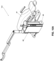
- FIG 10A shows the dental treatment unit 101 as it appears from the outside when connected to the connections box C1 ( Figure 7A ).
- the point of emergence of piping/wiring from the floor is covered by a specific housing 61, which is provided only in the case when the dental unit 101 is actually connected to a connections box C1. If the dental unit 101 is connected to a connections box C2 or C3, the aesthetic housing 61 is not provided.
- Figure 10B shows the dental treatment unit 101 as it appears from the outside when it is connected to the connections box C1 or C2 or C3.
- An aesthetic housing 441 covers the basis of the patient chair 41.
- a further aesthetic housing 63 covers the portion 556 of the base 511, and is always provided.
- the two aesthetic housings 441 and 63 are adjacent; on the adjacent walls of the housings 441 and 63 there are provided apertures allowing the passage of piping/wiring. On the floor there are no free piping/wiring.
- Figures 11A and 11B show the dental treatment unit 102 as it appears from the outside when it is connected to the connections box C1 ( Figure 8A ).
- An aesthetic housing 442 completely covers the base 512.
- Figure 11A shows the dental treatment unit 102 in a front view when it is connected to the connections box C1.
- Figure 11B shows that the point of emergence of piping/wiring from the floor is covered by a specific housing 62, which is provided only when said unit 102 is actually connected to a connections box C1. If the dental unit 102 is connected to a connections C3, the housing 62 is not provided.
- Figures 12A and 12B show the dental treatment unit 102 as it appears from the outside when it is connected to the connections box C3 ( Figure 8B ).
- Figure 12A shows the dental unit 102 in a front view.
- the aesthetic housing 442 completely covers the base 512, and is of reduced dimensions in order to allow the calf support 413 to reach its extreme position wherein it is perpendicular to the floor.
- An aesthetic housing 64 covers the connections box C3, and is in a visual-functional continuity with the housing 442.
- the aesthetic housing 442 is pre-set in order to connect it to the aesthetic housing 64: there are provided some apertures for the passage of piping/wiring.
- Figure 12B that is a rear view, shows that the aesthetic housing 61 is not provided, as in this case is useless.
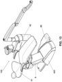
- Figure 13 shows the dental treatment unit 103 as it appears from the outside when it is connected to the connections box C2 or C3.
- An aesthetic housing 65 covers the portion 556 of the base 513, and is in a visual-functional continuity with the housing 443. From the outside it is not possible to tell whether the dental unit 103 is connected to a connections box C2 or C3, as the aesthetic housings 443 and 65 do not change.
- the aesthetic housing 443 is pre-set with apertures for the passage of piping/wiring in order to connect it to the aesthetic housing 65.
- the front wall of said housing 441, 442 is continuous.
- the wall of the housing 443 is continuous, while the housing 42 covering the hydrogroup is pre-set for the passage of piping/wiring.
- the wall of the aesthetic cover 441, 443 covering the chair base is provided for allowing the passage of connecting piping/wiring coming from the connections box C3.
- the bases 511, 512, 513 are components produced in metallic carpentry, which undergo suitable working for fixing the carpentry components that form the supporting structure 52 of the hydrogroup, preferably made of metal.
- the base 43 of the hydrogroup 42 and the bases 511, 512 form one piece: this allows to obtain a dental treatment unit with more stability.
- the method according to the present invention comprises the following steps:
Landscapes
- Health & Medical Sciences (AREA)
- Life Sciences & Earth Sciences (AREA)
- Animal Behavior & Ethology (AREA)
- General Health & Medical Sciences (AREA)
- Public Health (AREA)
- Veterinary Medicine (AREA)
- Nursing (AREA)
- Accommodation For Nursing Or Treatment Tables (AREA)
Abstract
- said hydrogroup comprising an internal support frame (52) substantially having the shape of a parallelepiped, provided with two opposed main sides parallel to the longitudinal axis of the patient chair (41), two opposed short sides perpendicular to said main sides, one of which is posterior i.e. oriented to the patient chair headrest (9), and the other is anterior, a lower hydrogroup base (43) oriented toward the floor and a hydrogroup top base supporting a bowl (3);
- there being provided piping and wiring for the connection to feeds and drain of said dental unit (101, 102, 103), said piping and wiring aimed at connecting a connections box (C1 or C2 or C3) placed in different points of the floor in an environment for installing said dental unit to an ingress point of said piping/wiring in said hydrogroup (42),
- a dental unit base (511, 512, 513) provided with a rear portion (552) and a slot (554) in its central portion; said dental unit base being optionally integral to the hydrogroup base (43);
characterized in that
the ingress of piping/wiring coming from one connections box (C1 or C2 or C3) into said hydrogroup (42) is fixed and is different and specific for each connections box (C1 or C2 or C3).

Description
- The present invention relates to dental treatment units, and in particular to a base and a hydrogroup for said units allowing an easy replacement of a dental treatment unit already installed in a dental practice with a new dental treatment unit.
- Dental treatment units have been industrially produced for several decades, and comprise a plurality of instruments allowing a dentist to administer dental therapies to a patient. Typically, they comprise a patient chair, a hydrogroup, a scialytic lamp, a dentist's board, an assistant's board generally provided with suction cannulas. In a known way, said patient chair comprises a headrest.
- In the art, there are known two main kinds of dental treatment units:
- Chair mounted dental treatment unit
wherein the hydrogroup is integral to the patient chair through a connecting arm, while the patient chair is fixed to the floor. The height of the hydrogroup varies at the same time as the chair height with respect to the floor. The patient chair is provided with a vertical movement typically performed by a pantograph or parallelogram mechanism. - Fixed hydrogroup dental treatment unit
wherein said hydrogroup is independent from the patient chair and is fixed to the floor, therefore its height from the floor never changes. The patient chair only performs a vertical movement, rising and lowering with respect to the floor and to the hydrogroup, which is stationary. - Among the dental treatment units provided with a fixed hydrogroup, there are provided two traditional configurations. The two configurations a and b have been known for a long time in the art, too.
- a. Floor mounted or free-stand dental treatment units
wherein the hydrogroup is fixed to the floor and the patient chair is mechanically independent from it; the controls used for moving the patient chair are placed on the dentist's board, which in some cases can be connected to the hydrogroup. The patient chair is provided with a base fixed to the floor, and rises and lowers with respect to the floor, generally using a pantograph or parallelogram mechanism. - b. Suspended chair dental treatment unit
in this case the hydrogroup fixed to the floor is provided with a rising and lowering mechanism connected to a supporting arm for the patient chair, which allows to raise and lower the patient chair, which moves on a vertical axis with respect to the hydrogroup, stationary on the floor. -
US3650033A1 of Siemens AG, published in 1972 , shows a patient chair of the chair mounted type, wherein the hydrogroup is integrally connected to the patient chair through a connecting arm, while the patient chair is fixed to the floor. In particular,Figure 2 ofUS3650033A1 shows a patient chair 1 and ahydrogroup 10 connected through a connecting arm 35. Aparallelogram arm 8 allows the rising and lowering of said patient chair 1, which thanks to its integral connections to thehydrogroup 10 through said arm 35, drags saidhydrogroup 10 raising and lowering it with respect to the floor. -
DE1932324U of Kaltenbach & Voigt, published in 1966 , describes a solution of the type a, i.e. with a floor mounted hydrogroup and an independent patient chair. Other documents of the known art describing floor mounted hydrogroup and independent patient chair are e.g.EP0100491A2 of Siemens, published in 1984 , andEP0895769A2, of Kaltenbach & Voigt again, published in 1999 . -
DE1822226U of EMDA, published in 1960 , describes a solution of the type b, i.e. a suspended chair dental treatment unit, with a hydrogroup fixed to the floor provided with a vertical movement for the patient chair with respect to the floor, well visible inFigure 2 ofDE1822226U . Other known art documents areEP2086489A1 of Kaltenbach & Voigt, published in 2009 , andEP2526916A1 of Planmeca, published in 2012 . - A further document describing a dental treatment unit is
US3524676A of Cocherell et al., published in 1970 . Such document describes another solution well known in the art, that is a dental treatment unit which can be used both by right-handed dentists and left-handed dentists. According to this document, "The unit is shiftable orbitally and laterally with respect to the chair so that the instrument center can be located in the correct position relative to the position of the headrest of the chair throughout the range of adjustment of the chair back." The invention described in this patent allows to move the hydrogroup (called dental unit 12) with respect to thepatient chair 11, in order to obtain alternatively a first configuration wherein the hydrogroup is placed on the right of the patient seated in the chair or a second configuration wherein the hydrogroup is placed on the left of the patient seated in the chair. In other words, a movement on the horizontal plane ofdental unit 12 with respect to thepatient chair 11 is provided. Nonetheless, the point of entry ofvacuum connection 52, electric connection 53, compressed air connection 54, water connection 55, and a drain or waste connection 56, i.e. the well 51, is located under thebase assembly 10, inside the outline of thepatient chair 11. These connections must allow the movement of thedental unit 12 around thepatient chair 11. - A further feature is that, in case of fixed hydrogroup dental units, the patient chair can alternatively provide:
- a seat formed by just one portion, supporting patient's thighs and calves;
- a seat comprising two articulated portions moving with respect to each other indicatively at patient's knee (see e.g.
US3578379A1 of Pennwalt, published in 1971 ). - The applicant, too, provides its customers with solutions similar to the above-described ones, in the form of chair mounted dental treatment units, in the form of floor mounted dental treatment units, and in the form of suspended chair dental treatment units. For better clarity,
Figures 1 show a chair mounted dental treatment unit presently produced by the applicant,Figures 2 show a floor mounted dental treatment unit presently produced by the applicant, andFigures 3 show a suspended chair dental treatment unit presently produced by the applicant. In particular,Figures 2 show a floor mounted dental unit provided with a patient chair comprising two articulated portions, the first portion supporting patient's thighs and the second portion supporting patient's calves. - The hydrogroup is a structural portion of the dental treatment unit, which generally allows to support the dental treatment unit portions different from patient chair, i.e. the assistant's board, the scialytic lamp, optionally the dentist's board, which in its turn supports a plurality of dental handpieces (dental syringe, micro-motor, turbine, polymerizing lamp, dental camera, etc.). Often the hydrogroup also supports a bowl and a water-to-cup spout. The hydrogroup is substantially a hollow structure housing reservoirs, electronic boards, piping and wiring. These components are hidden from view, so that the dental treatment unit shows a pleasing and reassuring look for patients.
- Said hydrogroup is substantially provided with the shape of a parallelepiped with six sides:
- two main sides, parallel to the longitudinal axis of patient chair, one of which sides is external, while the other is internal, i.e. oriented toward the patient chair;
- two short sides perpendicular to said main sides, one of which is oriented toward the headrest of patient chair (defined as posterior), while the other is oriented toward the foot support (defined as anterior);
- a lower base which in floor mounted and suspended chair dental units lies on the floor, while in chair mounted dental units never touches the floor;
- a top base supporting said bowl.
- It is worth noting that, although the metallic frame of the hydrogroup can be likened to a boxed body, in fact its faces are actually its two top and lower bases. Its four lateral faces are open; there are provided just the edges of the boxed body. The metallic frame of the hydrogroup is closed and hidden from view by an aesthetic housing, generally made of a suitable plastic material.
- Patient chair must be connected to electric energy for its movements; dental handpieces generally need be fed with electric energy, compressed air and water; suction cannulas must be connected to a suction device. Moreover, the liquids coming from the dental treatment unit must be conveyed to sewer drain. Generally, under the floor there are provided systems providing the necessary feeds, and the drain of liquids. These systems generally come out from the floor in contiguous points, forming a connections box.
- For the sake of clarity, in this document connections box relates to the set of all the supplies (i.e. suction, compressed air, water, electric energy and drain) that are needed for the functioning of dental units, i.e. the piping and wiring providing said supplies in their point of emersion from the floor, which piping and wiring are typically placed inside a small area, called connections box.
- Both for avoiding obstacles on the floor, and in order to make the dental environment more pleasing to the eye, generally said connections boxes are provided so as to arrive directly under the dental treatment unit; e.g. see
US3524676A of Cocherell et al . In this way, they remain hidden from view, once the dental treatment unit is installed in a dental practice. - The piping and wiring conveying suction, compressed air, water, electric energy and drain piping come out from said connections box, which generally lies on the floor; then their path continues in order to establish a connection to said dental treatment unit in a site called feeds entry point.
- In Western countries (Europe and USA), the number of dental treatment units sold in one year can be estimated to be around 60.000 units. The market of dental treatment units is a mature market, wherein the main part of dental treatment units, in a proportion of about 90/10, is acquired in order to replace a pre-existing dental treatment unit, already installed in a dental practice.
- Each manufacturer of dental treatment units provides its own characteristic arrangement of the internal organs of the hydrogroup, in particular with respect to the connections box. This allows to easily replace an already installed dental treatment unit with a new dental treatment unit provided with its connections box arranged in the same position.
- When wishing to buy a new dental treatment unit of a different model produced by the same manufacturer, or to buy a new dental treatment unit produced by a different manufacturer, dentists find themselves in the disagreeable situation of limiting their choice to a new dental treatment unit provided with a position of the connections box compatible with the dental treatment unit already installed in their dental practice.
- As can be observed in
Figure 4 , the positions of the connections boxes are characteristic and markedly different. When a model of dental treatment unit provided with a connections box arranged in a position different from that of the dental treatment unit already installed in a dental practice is chosen, the following alternative solutions are possible: - the new dental treatment unit must be translated in the space in order to exploit the existing connections box, but this could lead to collisions of the newly installed dental treatment unit with the dental practice walls or furniture;
- masonry works should be performed in order to move the connections box to a position compatible with the new dental treatment unit;
- the connections box and the feeds entry point of the new dental treatment unit could be connected through external piping running on the floor. Said piping represent an obstacle and pose a danger for dental staff and patients.
- Aim of the present invention is providing a dental treatment unit allowing to easily replace an already installed dental treatment unit with a new one, even when the already installed dental treatment unit is provided with a different arrangement of said connections box.
- This object is achieved by an apparatus and a method having the features of the independent claims. Advantageous embodiment and refinements are specified in the claims dependent thereon.
- It is worth specifying that the present invention is applicable to dental units of the type chair mounted dental treatment unit and floor mounted dental treatment unit.
- The present invention reaches this aim by providing a base allowing the connection of the feeds entry point in the hydrogroup with all the main positions of the connections boxes known in the art. Moreover, each of the connections boxes is covered by a respective aesthetic housing hiding feed piping and wiring (for suction, compressed air, water, electric energy and drain) from the view, from their point of exit from the floor and for a portion of such piping and wiring. Said aesthetic housings are provided adjacent and in continuity with the aesthetic housing covering the base of patient chair, so as to form a visual-functional unit, preventing the running of free piping and wiring on the floor, which poses a serious danger for the safety of dental staff and patients.
- Said bases are provided in different embodiments according to the kind of dental treatment unit, as will be made clearer in the following.
- Each base is substantially a plate optionally in continuity with the base of the hydrogroup lying on the floor. Each embodiment allows the passage of piping and wiring above said base. Moreover, said base cooperates with the structure of the hydrogroup. According to different cases, the ingress of piping and wiring is provided on the main side of the hydrogroup oriented toward the patient chair, or on the posterior short side of the hydrogroup, or on the front of the chair.
- There are provided three embodiments:
- A first embodiment is provided for floor mounted (fixed hydrogroup) dental units, wherein said base is provided with a T-shape, having the posterior arm of the base stretching toward the rear part of the dental treatment unit and the base of said T in continuity with the hydrogroup base;
- A second embodiment provided for floor mounted (fixed hydrogroup) dental units, similar to the first embodiment in the T posterior arm and the T-base in continuity with the hydrogroup base, wherein the anterior part is missing due to the fact that the patient chair is provided with an articulation between seat and calf support at the height of patient's knees;
- A third embodiment, provided for chair mounted dental units, very similar to the first embodiment, wherein said base is never in continuity with the hydrogroup base.
- The different kinds of bases are completed by specific aesthetic housings made of a suitable plastic material, aimed at covering the different connections boxes from view.
- The advantages of the present invention are manifold.
- A first advantage is easing and accelerating the replacement of a dental treatment unit already installed in a dental practice with a new one, by exploiting the already existing hydraulic/electric/pneumatic connections.
- A second advantage is the possibility of replacement without the need of masonry/hydraulic/electric/pneumatic works.
- The third advantage is the possibility of maintaining the same outline on the floor of the patient chair already installed in the dental practice, without the need to move the new dental treatment unit in order to connect it to the floor feeds already present. Therefore, for dental staff the room for manoeuvre remains the same.
- A fourth advantage is the improvement in safety for dental staff and patients, in that the aesthetic housings form a visual-functional continuity with the floor outline of the dental treatment unit, preventing the possibility of tripping in flying connections.
- A fifth advantage is that the aesthetic housings according to the invention are modular. According to the connections box already present in the dental practice, a housing can be chosen in order to obtain a dental treatment unit pleasing to the eye, but especially safe for dental staff and patients.
- Further advantages and properties of the present invention are disclosed in the following description, in which exemplary embodiments of the present invention are explained in detail based on the drawings:
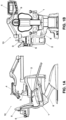
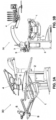
- Figure 1A, 1B
- Known art: chair mounted dental treatment unit, lateral and rear view;
- Figure 2A, 2B
- Known art: floor mounted dental treatment unit, lateral and rear view;
- Figure 3A, 3B
- Known art: suspended chair dental treatment unit, lateral and rear view;
- Figure 4
- Dental treatment unit according to the present invention shown in relationship with the main connections boxes, axonometric view without aesthetic housings, first embodiment;
- Figure 5
- Dental treatment unit according to the present invention shown in relationship with the main connections boxes, axonometric view without aesthetic housings, second embodiment;
- Figure 6
- Dental treatment unit according to the present invention shown in relationship with the main connections boxes, axonometric view without aesthetic housings, third embodiment;
- Figure 7A,7B, 7C
- First embodiment, hydrogroup with base with connection to connections box C1, C2, C3, respectively, axonometric view;
- Figure 8A, 8B
- Second embodiment, hydrogroup with base with connection to connections box C1, C3, respectively, axonometric view;
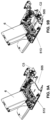
- Figure 9A, 9B
- Third embodiment, hydrogroup with base with connection to connections box C2, C3, respectively, axonometric view;
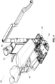
- Figure 9C
- Third embodiment, detail of the path of piping and wiring from the connections box to the inside of hydrogroup in chair mounted dental units;
- Figure 10A, 10B
- Fixed hydrogroup dental treatment unit, first embodiment with aesthetic housings, rear and front axonometric view;
- Figure 11A, 11B
- Fixed hydrogroup dental treatment unit, second embodiment with aesthetic housings for connecting to connections box C1, front and back axonometric view;
- Figure 12A, 12B
- Fixed hydrogroup dental treatment unit, second embodiment with aesthetic housings for connecting to connections box C3, front and back axonometric view;
- Figure 13
- Chair mounted dental treatment unit, second embodiment with aesthetic housings for connecting to connections box C2, C3, axonometric view;
- Figure 14
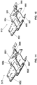
- Detail of the base according to the first embodiment, axonometric view;
- Figure 15
- Detail of the base according to the third embodiment, axonometric view;
- Figure 16
- Detail of the base according to the second embodiment, axonometric view.
-
Figures 1A, 1B show a chair mounteddental treatment unit 10 that is part of the present production of the applicant. Said chair mounted dental treatment unit comprises: a patient chair 1, ahydrogroup 2, abowl 3, a dentist'sboard 4, an assistant'sboard 5 and aheadrest 9. The vertical movement of the patient chair 1 is performed through a pantograph mechanism placed in the base of patient chair 1, provided with apantograph arm 6. The patient chair 1 and thehydrogroup 2 are integrally connected through a connecting arm 8 (visible inFigure 1B only), and therefore patient chair and hydrogroup rise and lower at the same time. -
Figures 2A, 2B show a floor mounteddental treatment unit 20 that is part of the present production of the applicant. Said floor mounted dental treatment unit comprises: a patient chair 1, ahydrogroup 2, abowl 3, a dentist'sboard 4, an assistant'sboard 5 and aheadrest 9. The vertical movement of the patient chair 1 is performed through a pantograph mechanism placed in the base of patient chair 1, provided with apantograph arm 6. As explained in the introduction, thehydrogroup 2 remains stationary, while the patient chair 1 rises and lowers with respect to the floor and the hydrogroup. The patient chair 1 and thehydrogroup 2 are substantially independent. The chair 1 is provided with asupport 11 for patient's thighs and asupport 12 for patient's calves, articulated at the level of patient's knees. -
Figures 3A, 3B show a suspended chairdental treatment unit 30 that is part of the present production of the applicant. Said suspended chair dental treatment unit comprises: a patient chair 1, ahydrogroup 2, abowl 3, a dentist'sboard 4, an assistant'sboard 5 and aheadrest 9. The vertical movement of the patient chair 1 is performed through a raising/lowering mechanism inside thehydrogroup 2, comprising a mechanism for raising and lowering the patient chair through an arm 7 (visible inFigure 3B only). As explained in the introduction, thehydrogroup 2 remains stationary, while the patient chair 1 rises and lowers with respect to thehydrogroup 2 and the floor. -
Figure 4 shows a simplified axonometric view of adental treatment unit 101 of a floor mounted dental unit according to the first embodiment of the present invention, comprising apatient chair 41 and ahydrogroup 42.Figure 4 shows the main alternative positions of the connections boxes C1, C2, C3 with respect topatient chair 41 andhydrogroup 42. Obviously, in reality, just one of the shown connections boxes is present on the floor of the dental practice, and to this connections box the already installed dental treatment unit is connected. In particular, there are shown the respective positions of - C1 connections box, placed at the rear end of the hydrogroup;
- C2 connections box, typical of the chair mounted dental units presently produced by the applicant and of
manufacturer 2; - C3 connections box, typical of
manufacturer 3. -
Figure 5 shows the second embodiment according to the present invention, with the main alternative positions of the connections boxes C1, C3 with respect to thepatient chair hydrogroup 42. In this second embodiment, the patient chair is provided with aseat 412 articulated with acalf support 413 at the height of patient's knees. In the position wherein both thebackrest 411 and thecalf support 413 are perpendicular to the floor, thecalf support 413 must not collide against the housing of the chair base, and therefore the chair base must be provided with dimensions more reduced with respect to the first embodiment. -
Figure 6 shows the third embodiment according to the present invention, with the main alternative positions of the connections boxes C2, C3 with respect to thepatient chair 41 andhydrogroup 42. As thehydrogroup 42 never touches the floor, in this embodiment the connection with the connections box C1 is not provided. - As can be observed in
Figures 4 ,5 ,6 , the positions of the different connections boxes are characteristic and markedly different. For instance, should a new dental treatment unit be connected to a connections box C3, masonry works would be needed in order to move the connections box. Alternatively, the new dental treatment unit should be translated in the space, but in the new position collisions might occur with dental practice walls or furniture. Alternatively, the connections box and the feeds entry point of the new dental treatment might be connected through external piping and wiring running freely on the floor, which are an obstacle and pose a danger for dental staff and patients. - The present invention allows reaching the feeds entry point inside the
hydrogroup 42 from any of the connections boxes C1 or C2 or C3 thanks to abase -
Figures 7A, 7B ,7C show the hydrogroup without itsaesthetic housing 42 allowing to appreciate the path of the piping/wiring coming from C1, C2 and C3 connections boxes, respectively, and the shape of the base 511 according to the first embodiment. Said hydrogroup comprises a knownmetallic frame 52 having a parallelepiped shape. Saidmetallic frame 52 is a frame supporting the functional internal components (not shown reservoirs, piping, electric boards, wiring), which is in its turn integral with saidbase 511. As can be appreciated by comparingFigures 7 , in the case of the connections box C1, piping and wiring enter into the hydrogroup by the posterior short side, while in the case of the connections boxes C2 and C3, the same piping and wiring enter into the hydrogroup by the internal main side. By internal main side the hydrogroup side oriented toward the patient chair is meant. - Said
base 511, which remains the same for all connections boxes C1, C2, C3, is provided with a substantial T-shape, with thebase 551 of said T adjacent to thebase 43 of saidmetallic structure 52, aposterior arm 552 and ananterior arm 558. Saidanterior arm 558 is provided with two prongs, afirst prong 556 and asecond prong 557, between which there is provided arecess 555. Thecentral portion 553 of said T is provided with aslot 554. -
Figure 7A shows the position of the connections box C1, which is adjacent to the posterior short side of themetallic structure 52, and in use is covered by a specific aesthetic housing, forming a visual-functional unit. -
Figure 7B shows the position of the connections box C3, which is placed in front of the base ofpatient chair 41, but nearer to the hydrogroup, and in use is covered by an aesthetic housing, forming a visual-functional unit. From the connections box C3, piping/wiring follow a path leading them to the feeds entry point inside said hydrogroup. -
Figure 7C shows the position of the connections box C2, which is placed in front of the base ofpatient chair 41 too, and in use is covered by an aesthetic housing, forming a visual-functional unit. In particular, the connections box C2 is placed inside saidrecess 555 provided between said twoprongs -
Figures 8A, 8B show the hydrogroup without theaesthetic housings 42 and allow to appreciate the path of piping/wiring coming from connections boxes C1 and C3, respectively, and the shape of the base 512 according to the second embodiment. Said hydrogroup comprises the knownmetallic frame 52 having a parallelepiped shape. Saidmetallic frame 52 is a frame supporting the functional internal components (not shown reservoirs, piping, electric boards, wiring), which is in its turn integral with saidbase 512. - Said
base 512, which remains the same for both connections boxes C1 and C3, in its rear position is provided with the same shape of thebase 511. Due to the fact that the base must support a patient chair provided with an articulated calf support 413 (seeFigure 5 ), the front portion of the T is missing, i.e. thefront arm 558 is missing. In the base 512 according to the second embodiment, thebase 551 of the T is adjacent to saidhydrogroup base 43, and there is provided therear arm 552. Thecentral portion 553 of the T is provided with saidslot 554. -
Figure 8A shows the position of the connections box C1, which is adjacent to the rear short side of themetallic structure 52, and in use is covered by a specific aesthetic housing, forming a visual-functional unit. -
Figure 8B shows the connections box C3, which is placed in front of the base ofpatient chair 41, but nearer to the hydrogroup, and in use is covered by a specific aesthetic housing, forming a visual-functional unit. From the connections box C3, piping/wiring follow a path leading them to the feeds entry point inside said hydrogroup. - As can be appreciated by comparing
Figures 8 , in the case of the connections box C1, piping and wiring enter into the hydrogroup by the posterior short side, while in the case of the connections boxes C2 and C3, the same piping and wiring enter into the hydrogroup by the internal main side. -
Figures 9A, 9B show the base of thepatient chair 41 without the aesthetic housing and allow to appreciate the path of piping/wiring coming from connections boxes C2 and C3, respectively, and the shape of the base 513 according to the third embodiment. In the case of the chair mounted dental units, the hydrogroup never touches the ground. Therefore, the position C1 of the connections box is not provided. The piping/wiring coming from the connections box C2 and C3 follow a path (visible inFigure 9C ) that provides, in its first portion downside the connections box, penetrating inside the housing covering thepantograph arm 6 supporting thepatient chair 41, then passing inside thearm 8 connecting thepatient chair 41 and thehydrogroup 42, and finally reaching the hydrogroup on its internal main side. -
Figure 10A shows thedental treatment unit 101 as it appears from the outside when connected to the connections box C1 (Figure 7A ). The point of emergence of piping/wiring from the floor is covered by aspecific housing 61, which is provided only in the case when thedental unit 101 is actually connected to a connections box C1. If thedental unit 101 is connected to a connections box C2 or C3, theaesthetic housing 61 is not provided. -
Figure 10B shows thedental treatment unit 101 as it appears from the outside when it is connected to the connections box C1 or C2 or C3. Anaesthetic housing 441 covers the basis of thepatient chair 41. A furtheraesthetic housing 63 covers theportion 556 of thebase 511, and is always provided. The twoaesthetic housings housings -
Figures 11A and 11B show thedental treatment unit 102 as it appears from the outside when it is connected to the connections box C1 (Figure 8A ). Anaesthetic housing 442 completely covers thebase 512. -
Figure 11A shows thedental treatment unit 102 in a front view when it is connected to the connections box C1.Figure 11B shows that the point of emergence of piping/wiring from the floor is covered by aspecific housing 62, which is provided only when saidunit 102 is actually connected to a connections box C1. If thedental unit 102 is connected to a connections C3, thehousing 62 is not provided. -
Figures 12A and 12B show thedental treatment unit 102 as it appears from the outside when it is connected to the connections box C3 (Figure 8B ).Figure 12A shows thedental unit 102 in a front view. Theaesthetic housing 442 completely covers thebase 512, and is of reduced dimensions in order to allow thecalf support 413 to reach its extreme position wherein it is perpendicular to the floor. Anaesthetic housing 64 covers the connections box C3, and is in a visual-functional continuity with thehousing 442. Theaesthetic housing 442 is pre-set in order to connect it to the aesthetic housing 64: there are provided some apertures for the passage of piping/wiring.Figure 12B , that is a rear view, shows that theaesthetic housing 61 is not provided, as in this case is useless. -
Figure 13 shows thedental treatment unit 103 as it appears from the outside when it is connected to the connections box C2 or C3. Anaesthetic housing 65 covers theportion 556 of thebase 513, and is in a visual-functional continuity with thehousing 443. From the outside it is not possible to tell whether thedental unit 103 is connected to a connections box C2 or C3, as theaesthetic housings aesthetic housing 443 is pre-set with apertures for the passage of piping/wiring in order to connect it to theaesthetic housing 65. - The comparison of the
Figures 14 and 15 allows to appreciate that the twobases portion 556. - On the other hand, the comparison between the
Figures 14 and 15 on the one side and theFigure 16 on the other side allows to observe that the base 512 according to the second embodiment is completely missing thefront portion 558. - In the case of the connections box C1, the front wall of said
housing housing 443 is continuous, while thehousing 42 covering the hydrogroup is pre-set for the passage of piping/wiring. In the cases of the connections boxes C3 shown inFigures 10 and13 , the wall of theaesthetic cover - The
bases structure 52 of the hydrogroup, preferably made of metal. - In an embodiment, the
base 43 of thehydrogroup 42 and thebases - The method according to the present invention comprises the following steps:
- Removing an already installed
dental treatment unit - Placing a new
dental treatment unit dental chair 41 in the same outline on the floor as the removed patient chair 1, connecting the pre-existing connections box C1 or C2 or C3 with the feeds entry point of the newdental treatment unit aesthetic housings - Optionally covering the path of connecting piping/wiring with a further suitable
aesthetic housing - 1
- patient chair
- 2
- hydrogroup
- 3
- bowl
- 4
- dentist's board
- 5
- assistant's board
- 6
- pantograph arm
- 7
- chair-hydrogroup connecting arm
- 8
- chair-hydrogroup connecting arm
- 9
- headrest
- 10
- chair mounted dental treatment unit
- 11
- thigh support
- 12
- calf support
- 20
- floor mounted or free-stand dental treatment units
- 30
- suspended chair dental treatment unit
- C1
- position of CEFLA and of manufacturer 1 connections box
- C2
- position of CEFLA chair mounted dental treatment unit and of
manufacturer 2 connections box - C3
- position of
manufacturer 3 connections box - 41
- patient chair
- 42
- hydrogroup
- 43
- hydrogroup base
- 44
- housing for connections box C1
- 52
- metal frame
- 61
- housing for connections box C1
- 62
- housing for connections box C1
- 63
- housing for connections box C3
- 64
- housing for connections box C3
- 65
- housing for connections box C3
- 101
- dental treatment unit first embodiment
- 102
- dental treatment unit second embodiment
- 103
- dental treatment unit third embodiment
- 411
- backrest
- 412
- thigh support
- 413
- calf support
- 441
- housing for chair base, first embodiment
- 442
- housing for chair base, second embodiment
- 443
- housing for chair base, third embodiment
- 511
- dental unit base first embodiment
- 512
- dental unit base second embodiment
- 513
- dental unit base third embodiment
- 551
- T base
- 552
- T rear arm
- 553
- T central portion
- 554
- T slot
- 555
- T recess
- 556
- protrusion
- 557
- protrusion
- 558
- T front arm
Claims (13)
- Dental treatment unit (101, 102, 103) set up for fixing to a floor, comprising a patient chair (41) and a hydrogroup (42);- said hydrogroup comprising an internal support frame (52) substantially having the shape of a parallelepiped, provided with two opposed main sides parallel to the longitudinal axis of the patient chair (41), two opposed short sides perpendicular to said main sides, one of which is posterior i.e. oriented to the patient chair headrest (9), and the other is anterior, a lower hydrogroup base (43) oriented toward the floor and a top hydrogroup base supporting a bowl (3);- there being provided piping and wiring for the connection to feeds and drain of said dental unit (101, 102, 103), said piping and wiring aimed at connecting a connections box (C1 or C2 or C3) placed in different points of the floor in an environment for installing said dental unit to an ingress point of said piping/wiring in said hydrogroup (42),- a dental unit base (511, 512, 513) provided with a rear portion (552) and a slot (554) in its central portion; said dental unit base being optionally integral to the hydrogroup lower base (43);characterized in that
the ingress of piping/wiring coming from one connections box (C1 or C2 or C3) into said hydrogroup (42) is fixed and is different and specific for each connections box (C1 or C2 or C3). - Dental treatment unit (101, 102, 103) comprising said dental unit base (511, 512, 513) according to claim 1, wherein said connections box (C1 or C2 or C3), is placed at a distance from feeds entry point (50), and wherein the path from said connections box (C1 or C2 or C3), to said feeds entry point (50) is at least partially covered by a respective aesthetic housing hiding from the view feed piping and wiring supplying suction, compressed air, water, electric energy and drain; said aesthetic housings being provided adjacent and in continuity with the aesthetic housing covering the base of patient chair, so as to form a visual-functional unit.
- Dental treatment unit (101, 102, 103) comprising said dental unit base (511, 512, 513) according to claim 1, suitable for connecting said dental unit (101, 102, 103) comprising a patient dental chair (1) to a pre-existing fixed connections box (C1 or C2 or C3), said connections box having been previously connected to another dental treatment unit (10 or 20 or 30) to be replaced, said dental unit base (511, 512, 513) allowing to place said patient chair (41) in the same outline on the floor as the replaced patient dental chair (1).
- Dental treatment unit (101, 102, 103) comprising said dental unit base (511, 512, 513) according to claim 1, wherein no movement on the horizontal plane, i.e. a plane parallel to the floor, of said patient chair (41) with respect to said hydrogroup (42) and vice versa is provided.
- Dental treatment unit (101, 102, 103) comprising said dental unit base (511, 512, 513) according to claim 1, wherein said base (511, 512, 513) comprises at least a recess for housing a connections box (C2, C3), especially for a position of said connections box (C2, C3) in an intermediate position (C3) between the base of said patient chair (41) and the base (43) of said hydrogroup (42) and for a position (555) of said connections box (C2) on the front side of the base of said patient chair (41).
- Dental treatment unit (101, 102, 103) comprising said dental unit base (511, 512, 513) according to claim 1 or 5, wherein said dental unit base (511, 512, 513) is provided with a T-shape, comprising- a T-base (551) oriented toward said hydrogroup (42), optionally in continuity with said base (43) of said hydrogroup,- a rear arm (552), with reference to the antero-posterior orientation of the patient chair (41),- a central slot (554).
- Dental treatment unit (101, 103) comprising said dental unit base (511, 513) according to claim 6, wherein said dental unit base (511, 513) further comprises a front portion (558) provided with two prongs (556 and 557) defining a recess (555) between them.
- Dental treatment unit (102) comprising said dental unit base (512) according to claim 6, wherein said dental unit base (512) only comprises said rear arm (552), central slot (554) and T-base (551).
- Dental treatment unit (101, 102) comprising said dental unit base (511, 512) according to one or more of the preceding claims, wherein said dental unit base (511, 512) is realized as an element fixable/fixed to said base (43) of hydrogroup (42), or it is obtained as a unique piece, i.e. integral and in continuity with said base (43) of the hydrogroup (42).
- Dental treatment unit (101, 102, 103) comprising said dental unit base (511, 512, 513) according to one or more of the preceding claims, wherein said dental unit base (511, 512, 513) is provided with at least a hole for the fixing of said dental unit (101, 102, 103) to the floor through wall plugs or suitable fixing means.
- Dental treatment unit (101, 102, 103) comprising said dental unit base (511, 512, 513) according to one or more of the preceding claims, wherein the base of the patient chair (41) is covered by a single aesthetic cover (441, 442, 443), whose wall is continuous and/or the hydrogroup is covered by a housing (42) whose wall is continuous.
- Dental treatment unit (101, 102, 103) comprising said dental unit base (511, 512, 513) according to one or more of the preceding claims, wherein each connections box (C1 or C3) is covered by a respective aesthetic housing (61 or 63 or 63 or 64 or 65) that is in visual and/or functional continuity with said aesthetic housing (441, 442, 443) covering the base of patient chair or with the aesthetic housing (42) of the hydrogroup, wherein the side of said aesthetic housing (441, 442, 443) is set up for the connection with said further aesthetic housing (61 or 63 or 64 or 65).
- Method for replacing a dental unit (10, 20, 30) already installed in a dental practice with a new dental unit (101, 102, 103) according to one or more of claims 1-12, said method comprising the following steps:- Removing a dental treatment (10 or 20 or 30) already installed in a dental practice;- Positioning the new dental treatment unit (101 or 102, or 103) in said dental practice, connecting the pre-existing connections box (C1 or C2 or C3) with the feeds entry point inside said hydrogroup of the new dental unit (101 or 102 or 103) and covering with the aesthetic housings (441 or 442 or 443 and 63 or 65);- Optionally covering the path of connecting piping/wiring with a further appropriate aesthetic housing (61 or 62 or 64),characterized in that
the new patient chair (41) is positioned in the same outline on the floor as the outline of the removed patient chair (1).
Applications Claiming Priority (1)
| Application Number | Priority Date | Filing Date | Title |
|---|---|---|---|
| IT102022000018648A IT202200018648A1 (en) | 2022-09-13 | 2022-09-13 | DENTAL TREATMENT UNIT COMPATIBLE WITH DIFFERENT CONNECTION BOXES |
Publications (1)
| Publication Number | Publication Date |
|---|---|
| EP4338721A1 true EP4338721A1 (en) | 2024-03-20 |
Family
ID=84331342
Family Applications (1)
| Application Number | Title | Priority Date | Filing Date |
|---|---|---|---|
| EP23196568.2A Pending EP4338721A1 (en) | 2022-09-13 | 2023-09-11 | Dental treatment unit compatible with different connections boxes |
Country Status (2)
| Country | Link |
|---|---|
| EP (1) | EP4338721A1 (en) |
| IT (1) | IT202200018648A1 (en) |
Citations (9)
| Publication number | Priority date | Publication date | Assignee | Title |
|---|---|---|---|---|
| DE1822226U (en) | 1960-09-17 | 1960-11-24 | Emda | DENTAL HEIGHT-ADJUSTABLE TREATMENT CHAIR. |
| DE1932324U (en) | 1965-12-04 | 1966-02-10 | Kaltenbach & Voigt | UNIT DENTAL DEVICE. |
| US3524676A (en) | 1967-08-04 | 1970-08-18 | Francis E Cocherell | Dental apparatus |
| US3578379A (en) | 1967-12-28 | 1971-05-11 | Pennwalt Corp | Adjustable chair |
| US3650033A (en) | 1968-10-26 | 1972-03-21 | Siemens Ag | Dental treatment units |
| EP0100491A2 (en) | 1982-08-02 | 1984-02-15 | Siemens Aktiengesellschaft | Dental chair |
| EP0895769A2 (en) | 1997-07-30 | 1999-02-10 | Kaltenbach & Voigt Gmbh & Co. | Chair for medical or dental care |
| EP2086489A1 (en) | 2006-10-31 | 2009-08-12 | Kaltenbach & Voigt GmbH | Dental treatment chair |
| EP2526916A1 (en) | 2006-11-21 | 2012-11-28 | Planmeca Oy | Integrated dental care apparatus |
-
2022
- 2022-09-13 IT IT102022000018648A patent/IT202200018648A1/en unknown
-
2023
- 2023-09-11 EP EP23196568.2A patent/EP4338721A1/en active Pending
Patent Citations (9)
| Publication number | Priority date | Publication date | Assignee | Title |
|---|---|---|---|---|
| DE1822226U (en) | 1960-09-17 | 1960-11-24 | Emda | DENTAL HEIGHT-ADJUSTABLE TREATMENT CHAIR. |
| DE1932324U (en) | 1965-12-04 | 1966-02-10 | Kaltenbach & Voigt | UNIT DENTAL DEVICE. |
| US3524676A (en) | 1967-08-04 | 1970-08-18 | Francis E Cocherell | Dental apparatus |
| US3578379A (en) | 1967-12-28 | 1971-05-11 | Pennwalt Corp | Adjustable chair |
| US3650033A (en) | 1968-10-26 | 1972-03-21 | Siemens Ag | Dental treatment units |
| EP0100491A2 (en) | 1982-08-02 | 1984-02-15 | Siemens Aktiengesellschaft | Dental chair |
| EP0895769A2 (en) | 1997-07-30 | 1999-02-10 | Kaltenbach & Voigt Gmbh & Co. | Chair for medical or dental care |
| EP2086489A1 (en) | 2006-10-31 | 2009-08-12 | Kaltenbach & Voigt GmbH | Dental treatment chair |
| EP2526916A1 (en) | 2006-11-21 | 2012-11-28 | Planmeca Oy | Integrated dental care apparatus |
Also Published As
| Publication number | Publication date |
|---|---|
| IT202200018648A1 (en) | 2024-03-13 |
Similar Documents
| Publication | Publication Date | Title |
|---|---|---|
| CN102639029B (en) | Telescopic column, preferably for furniture | |
| US7195219B2 (en) | Modular dental chair equipment mounting system | |
| US4646211A (en) | Service outlet wall and rail system for use thereon | |
| JP5871869B2 (en) | Integrated dental treatment device | |
| EP4338720B1 (en) | Dental treatment unit compatible with various connection doses | |
| CN213607956U (en) | Knee joint rehabilitation training chair | |
| CN206651963U (en) | Modular construction for dental treatment unit | |
| US20200107984A1 (en) | Adjustable Surgical Chair | |
| US8408899B1 (en) | Dental delivery systems, related components and methods | |
| JPH08289909A (en) | Supply unit | |
| CN101583333A (en) | Integrated dental care apparatus | |
| CN108261221B (en) | Mandible cuts bone baffle | |
| JPH077934Y2 (en) | Swing arm for supporting patient saliva suction nozzle in dental chair | |
| US3295206A (en) | Dental equipment | |
| US3418714A (en) | Device for variable height positioning of treatment appliances on dental equipment | |
| WO2022049729A1 (en) | Vacuum suction-nozzle for dental treatment, vacuum for dental treatment, and dental treatment device | |
| CN201026239Y (en) | Podosoma treating bracket | |
| CN215535572U (en) | An ocular drug delivery device for glaucoma treatment | |
| CN211094697U (en) | Liftable operation terminal | |
| JP6784832B2 (en) | Dental chair and dental chair footswitch | |
| CN218008675U (en) | Double-person lifting table | |
| EP0116184A1 (en) | System of adjusting height and length of a bed frame | |
| USD1057952S1 (en) | Medical imaging stand | |
| CN217525477U (en) | Adjusting device for orthodontic mouth gag | |
| JP6482422B2 (en) | Medical console unit |
Legal Events
| Date | Code | Title | Description |
|---|---|---|---|
| PUAI | Public reference made under article 153(3) epc to a published international application that has entered the european phase |
Free format text: ORIGINAL CODE: 0009012 |
|
| STAA | Information on the status of an ep patent application or granted ep patent |
Free format text: STATUS: THE APPLICATION HAS BEEN PUBLISHED |
|
| AK | Designated contracting states |
Kind code of ref document: A1 Designated state(s): AL AT BE BG CH CY CZ DE DK EE ES FI FR GB GR HR HU IE IS IT LI LT LU LV MC ME MK MT NL NO PL PT RO RS SE SI SK SM TR |
|
| STAA | Information on the status of an ep patent application or granted ep patent |
Free format text: STATUS: REQUEST FOR EXAMINATION WAS MADE |
|
| 17P | Request for examination filed |
Effective date: 20240809 |
|
| RBV | Designated contracting states (corrected) |
Designated state(s): AL AT BE BG CH CY CZ DE DK EE ES FI FR GB GR HR HU IE IS IT LI LT LU LV MC ME MK MT NL NO PL PT RO RS SE SI SK SM TR |
|
| STAA | Information on the status of an ep patent application or granted ep patent |
Free format text: STATUS: EXAMINATION IS IN PROGRESS |
|
| 17Q | First examination report despatched |
Effective date: 20250917 |