EP4338345B1 - Anpassung der überwachung eines physikalischen downlink-steuerkanals mit mehreren zuständen - Google Patents
Anpassung der überwachung eines physikalischen downlink-steuerkanals mit mehreren zuständen Download PDFInfo
- Publication number
- EP4338345B1 EP4338345B1 EP22724941.4A EP22724941A EP4338345B1 EP 4338345 B1 EP4338345 B1 EP 4338345B1 EP 22724941 A EP22724941 A EP 22724941A EP 4338345 B1 EP4338345 B1 EP 4338345B1
- Authority
- EP
- European Patent Office
- Prior art keywords
- wireless device
- pdcch
- sssg
- network
- duration
- Prior art date
- Legal status (The legal status is an assumption and is not a legal conclusion. Google has not performed a legal analysis and makes no representation as to the accuracy of the status listed.)
- Active
Links
Images


Classifications
-
- H—ELECTRICITY
- H04—ELECTRIC COMMUNICATION TECHNIQUE
- H04L—TRANSMISSION OF DIGITAL INFORMATION, e.g. TELEGRAPHIC COMMUNICATION
- H04L5/00—Arrangements affording multiple use of the transmission path
- H04L5/003—Arrangements for allocating sub-channels of the transmission path
- H04L5/0053—Allocation of signalling, i.e. of overhead other than pilot signals
-
- H—ELECTRICITY
- H04—ELECTRIC COMMUNICATION TECHNIQUE
- H04L—TRANSMISSION OF DIGITAL INFORMATION, e.g. TELEGRAPHIC COMMUNICATION
- H04L5/00—Arrangements affording multiple use of the transmission path
- H04L5/0091—Signalling for the administration of the divided path, e.g. signalling of configuration information
- H04L5/0094—Indication of how sub-channels of the path are allocated
-
- Y—GENERAL TAGGING OF NEW TECHNOLOGICAL DEVELOPMENTS; GENERAL TAGGING OF CROSS-SECTIONAL TECHNOLOGIES SPANNING OVER SEVERAL SECTIONS OF THE IPC; TECHNICAL SUBJECTS COVERED BY FORMER USPC CROSS-REFERENCE ART COLLECTIONS [XRACs] AND DIGESTS
- Y02—TECHNOLOGIES OR APPLICATIONS FOR MITIGATION OR ADAPTATION AGAINST CLIMATE CHANGE
- Y02D—CLIMATE CHANGE MITIGATION TECHNOLOGIES IN INFORMATION AND COMMUNICATION TECHNOLOGIES [ICT], I.E. INFORMATION AND COMMUNICATION TECHNOLOGIES AIMING AT THE REDUCTION OF THEIR OWN ENERGY USE
- Y02D30/00—Reducing energy consumption in communication networks
- Y02D30/70—Reducing energy consumption in communication networks in wireless communication networks
Definitions
- the present disclosure relates, in general, to wireless communications and, more particularly, systems and methods for multi-states Physical Downlink Control Channel (PDCCH) monitoring adaptation.
- PDCCH Physical Downlink Control Channel
- Physical downlink control channel (PDCCH) monitoring in the active time is one of the most power-consuming activities in user equipment (UE).
- UE user equipment
- monitoring for PDCCH in the absence of data may be the dominant source of energy consumption in enhanced mobile broadband (eMBB) in typical scenarios.
- eMBB enhanced mobile broadband
- MOs unnecessary PDCCH monitoring occasions
- the UE monitors PDCCH in every slot so that the UE always be ready for data transmission and, thus, delay of the transmission is minimized. This might not be beneficial, however, from the perspective of UE power consumption.
- IAT inactivity timer
- the highest energy saving can be expected from reducing PDCCH monitoring during the IAT durations. During this duration, it is desirable to be in sparse monitoring such as, for example, every 2 nd , 4 th , or 8 th slot.
- 3GPP introduced a search-space set group (SSSG) switching feature which is applicable for NR unlicensed (NR-U).
- SSSG search-space set group
- NR-U NR unlicensed
- two groups of search space (SS)-sets can be configured in Rel-16. If configured (through the RRC parameters searchSpaceGroupIdList- r16 and searchSpaceSwitchingGroup-r16 .), then the UE can be switched between these two groups using either explicit or implicit mechanisms. Some SSs may not appear in the SS-sets. Such SSs will always be monitored, and monitoring of such SSs is not impacted by the SSSG-switching mechanism.
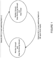
- FIGURE 1 illustrates an explicit Search Space Set Switching Mechanism.
- the UE can be switched between the two SSSGs through detection of DCI format 2_0. This is done by configuring the UE with the RRC parameter searchSpaceSwitchTrigger-r16 which provides a location for the SSSG-switching field (for a serving cell) in the DCI format 2_0.
- the SSSG-switching field is one bit in size, where a bit value of zero indicates the first group and a value of one indicates the second group.
- These two groups may be referred to as group0 and group1, where the SSSG-switching field takes the values zero and one, respectively.
- FIGURE 2 illustrates an implicit search space set switching mechanism. The procedure is as follows:
- DCI format 2_0 is configured in the common SS and potentially affects group transitions for all UEs with the same SFI-RNTI decoding the DCI; i.e. the SSSG-switching is not controlled on a UE-basis.
- a UE can be configured with up to 10 search spaces.
- Cell groups are defined for SSSG-switching such that if SS-set switching is triggered for one cell in the group of cells, it also triggers SS-set switching for all cells in the corresponding group. In Rel-16, four cell-groups are specified.
- Exploiting the SSSG-switching for UE power-saving can be done, for example, by configuring the first SSSG (e.g., SSSGO) to have sparse PDCCH monitoring occasions (MOs) and the second SSSG (e.g., SSSG1) to have dense PDCCH MOs.
- the UE monitors PDCCH according to the first SSSG when there is no data burst and switch to SSSG1 when the data burst comes.
- the UE then can switch back to SSSG0 when the data burst ends.
- PDCCH-skipping the idea is to configure the UE with a certain skipping duration. If the UE receives the skipping indication, the UE may skip PDCCH monitoring for the configured duration. When the skipping duration ends, the UE then goes back to monitor the PDCCH according to the SSs.
- PDCCH-skipping may be in terms of "one-shot" PDCCH-skipping.
- the network (NW) will not send PDCCHs inside the PDCCH-skipping duration.
- the UE may omit PDCCH monitoring and sleep during the PDCCH-skipping duration.
- PDCCH-skipping may also be in terms of "periodic" skipping, in which the UE is configured with a certain sleep-and-awake pattern, which may be called a skipping pattern. During the sleep part of the skipping pattern, the UE does not expect to receive PDCCH from the NW, and the UE can sleep during this duration. On the other hand, the UE needs to awake to monitor PDCCH during the awake duration of the pattern as the NW may send PDCCH in this duration.
- the UE may be configured with one skipping duration/pattern.
- the bit indication is used to determine whether the UE could skip monitor PDCCH or not.
- the UE may be configured with more than one skipping duration or pattern. In this case, the bit combination in the skipping indication points out which skipping duration/pattern should be applied by the UE.
- the UE may be configured with an SSSG index for each configured SS to accommodate the SSSG-switching feature.
- the UE may also in the same RRC configuration instance be configured with a certain skipping duration, i.e., to accommodate the PDCCH-skipping feature.
- certain previous methods use a 2-bit indication to differentiate between the skipping and switching command. For example, the following bit combination can be used:
- a more general term "network node” may be used and may correspond to any type of radio network node or any network node, which communicates with a UE (directly or via another node) and/or with another network node.
- network nodes are NodeB, eNodeB (eNB), gNodeB (gNB) Master eNodeB (MeNB), a network node belonging to Master Cell Group (MCG) or Secondary Cell Group (SCG), base station (BS), multi-standard radio (MSR) radio node such as MSR BS, network controller, radio network controller (RNC), base station controller (BSC), relay, donor node controlling relay, base transceiver station (BTS), access point (AP), transmission points, transmission nodes, Remote Radio Unit (RRU), Remote Radio Head (RRH), nodes in distributed antenna system (DAS), core network node (e.g.
- MSC Mobile Switching Center
- MME Mobility Management Entity
- O&M Operations & Maintenance
- OSS Operations Support System
- SON Self Organizing Node
- positioning node e.g. Evolved-Serving Mobile Location Center (E-SMLC)
- MDT Minimization of Drive Tests
- test equipment physical node or software
- the non-limiting term user equipment (UE) or wireless device may be used and may refer to any type of wireless device communicating with a network node and/or with another UE in a cellular or mobile communication system.
- UE are target device, device to device (D2D) UE, machine type UE or UE capable of machine to machine (M2M) communication, Personal Digital Assistant (PDA), Tablet, mobile terminals, smart phone, laptop embedded equipped (LEE), laptop mounted equipment (LME), Unified Serial Bus (USB) dongles, UE category M1, UE category M2, Proximity Services UE (ProSe UE), Vehicle-to-Vehicle UE (V2V UE), Vehicle-to-Vehicle UE (V2X UE), etc.
- D2D device to device
- M2M machine to machine
- PDA Personal Digital Assistant
- Tablet tablet
- smart phone smart phone
- LME laptop embedded equipped
- LME laptop mounted equipment
- USB Unified Serial Bus
- UE category M1 UE
- a method for describing the relationship between each state of the PDCCH monitoring adaptation feature, where the PDCCH monitoring adaptation feature consists of PDCCH-skipping and SSSG-switching.
- the PDCCH monitoring adaptation feature consists of PDCCH-skipping and SSSG-switching.
- certain embodiments disclosed herein provide mechanisms for how the UE should transition between PDCCH monitoring adaptation states, in particular, for example, when the transition is initiated by conditions other than explicit DCI indication.
- certain embodiments may provide possible additional information that can be contained in the DCI indication (on top of state transition indication is also given).
- a method, implemented in a UE configured with more than two PDCCH monitoring states may include:
- a wireless device such as, for example, a UE is configured such as by, for example, RRC configurations, for one or more cells, or group of cells, or bandwidth parts (BWPs), with the first SSSG (e.g., SSSGO) and the second SSSG (e.g., SSSG1).
- the wireless device may also be configured with a skipping duration.
- the skipping duration can be counted starting from the time the UE receives the skipping indication.
- the skipping duration can be counted starting from the end of the application delay.
- the UE may also optionally be configured with a timer such as, for example, a SSSG-switching timer.
- the wireless device may be configured with the first SSSG containing SSs having dense PDCCH , and the second SSSG containing SSs having sparse PDCCH MOs.
- first SSSG may include PDCCH monitoring in every slot
- second SSSG includes PDCCH monitoring in every 4 th slot.
- the determination of the configuration of the first and second SS-set group (e.g., periodicity, duration, etc.) and the skipping duration for example, can be based on the scheduling flexibility expected by the NW, QoS target, expected traffic, UE power saving metric, etc.
- the wireless device may skip PDCCH monitoring during the skipping duration.
- the wireless device should return to monitoring the PDCCH according to, at least, one of the SSSGs.
- the wireless device may monitor PDCCH according to a predetermined SSSG such as, for example, that defined through a specification.
- a predetermined SSSG such as, for example, that defined through a specification.
- the wireless device may be simply configured (e.g., through standardization) to monitor either according to SSSG0 or SSSG1 after the skipping duration ends.
- the wireless device may return to the SSSG that is associated with the denser PDCCH monitoring.
- the wireless device will return to SSSG0 after the duration ends. Having the UE go to denser SSSG monitoring after PDCCH skipping is beneficial in minimizing the latency and throughput loss.
- the SSSG-switching timer does not restart (SSSGO is basically the default SSSG).
- SSSGO is basically the default SSSG.
- the UE will always be in SSSG0 except if it is indicated to change to another SSSG via DCI. Therefore, it is easier to get synced between the NW and the UE.
- the wireless device should finish the PDCCH skipping duration first.
- a reason for letting the UE finish the skipping duration first is that the skipping is indicated by a more specific codepoint in the DCI (codepoint that represents skipping).
- the SSSG-switching timer (re)starts when the UE is indicated with no-skipping, indicated with skipping, or indicated to switch to SSSG1 (or SSSG2 if configured).
- certain embodiments may provide the PDCCH skipping indication a higher priority than the SSSG transition indication.
- the determination on which SS-set group the wireless device has to monitor PDCCH may depend on the status of the SSSG-switching timer. For example, if the SSSG-switching timer ends after the skipping duration ends, the wireless device may return to monitor PDCCH according to SSSGO; and if the SSSG-switching timer does not yet end after the skipping duration ends, the UE may return to monitor PDCCH according to SSSG1. In an additional example scenario, when returning to SSSG1, the UE may continue the SSSG-switching timer. In another example embodiment, when returning to SSSG1, the UE may restart the SSSG-switching timer.
- the wireless device may monitor PDCCH in SSSG1, and receive a PDCCH skipping command with a duration, e.g., X ms. The wireless device may then stop monitoring PDCCH in SSSG1 for the X ms duration, and start monitoring SSSG0 within the skipping duration if the SS switching timer ends before the end of the X ms skipping duration if it is configured as such.
- a duration e.g., X ms.
- the wireless device may monitor PDCCH according to the SSSG from which the wireless device enters the PDCCH-skipping state. For example, if the wireless device monitors PDCCH according to the first SSSG (e.g., SSSGO) before receiving the PDCCH-skipping command, the wireless device will return monitoring PDCCH according to the first SSSG (e.g., SSSGO).
- the first SSSG e.g., SSSGO
- the wireless device will return monitoring PDCCH according to the first SSSG (e.g., SSSGO).
- the determination in which the wireless device should monitor PDCCH can be configurable in the network, e.g., in the RRC configuration.
- the wireless device may still perform the configured activities, e.g., periodic/semi-periodic CSI report, SRS transmission, RRM/RLM/BFD measurements, and configured grants remain in place for the wireless device.
- the wireless device may be allowed to relax one or more of such configured activities during the skip duration either by higher layer NW configuration or by pre-configuration, e.g., as in standardization documentations.
- the wireless device may also be configured with a switching timer.
- the basic switching timer behavior can be based on the switching timer behavior of the SSSG switching feature of Release 16 NR-U, i.e., the wireless device will start (and restart) the switching timer when the wireless device receives an indication to monitor PDCCH according to SSSG1. The wireless device then returns to monitor PDCCH according to SSSG0 when the switching timer expires.
- the value of the switching timer can be, for example, based on QoS target, UE power-saving metric, expected traffic, etc.
- the wireless device may be currently monitoring PDCCH according to SSSG1 while the switching timer is running. The wireless device may then receive an indication to enter the PDCCH-skipping state. In one example, the wireless device may keep the switching timer counting irrespective of the PDCCH-skipping indication. In another example, the wireless device may also restart the switching timer when it receives a PDCCH-skipping indication. In yet another example, the wireless device may pause the switching timer during the skipping duration and continue counting when the skipping duration ends, and the wireless device returns monitoring PDCCH according to SSSG1.
- the value of the switching timer is limited to a certain maximum value. This may not be beneficial when the network wants to rely on the DCI indication for switching between SSSGs. Therefore, in one example, a value of infinity may be added to the switching timer possible values.
- the wireless device configured with a switching timer with a value of inf may remain on the SSSG1, at least, until the IAT expires if it does not receive any explicit switching or skipping indication.
- the network may have the option to not configure the switching timer.
- the wireless device may receive a SSSG-switching/PDCCH skipping configuration without the switching timer, and thus the wireless device may remain in an indicated state until it is explicitly indicated otherwise by receiving a DCI or a pre-configured event, e.g., transmitting a PRACH, using a configured grant to transmit PUSCH, transmitting a UL request, detection of beam failure and this starting beam failure recovery procedure, etc.
- the value of the configured SSSG-switching timer may be used as a restriction for the skipping duration. For example, if the wireless device is configured with an SSSG-switching timer with a value of X ms, the maximum value of the skipping duration is Y ms where Y ⁇ X.
- the UE may be configured with the switching timer and the corresponding behavior through higher layer signaling, e.g., RRC signaling.
- higher layer signaling e.g., RRC signaling.
- the bit indication is used either to switch to (or remain in) a certain SSSG or to indicate the UE that the UE could skip PDCCH monitoring for a certain duration.
- the indication bits may also be used to bring additional information.
- the different bit combinations may indicate different mechanisms related to the switching timer such as, for example, whether the switching timer should start (or restart).
- a wireless device indicated by the first bit-combination may switch from the first SSSG (e.g., SSSGO) to the second SSSG (e.g., SSSG1) and starts the switching timer.
- the wireless device may switch from the first SSSG (e.g., SSSGO) to the second SSSG (e.g., SSSG1) and may not start the switching timer.
- the following bit combination can be used when the wireless device is configured with 2-bit indication, 2 SSSGs, and one PDCCH-skipping duration.
- Switching to SSSG1 without activating the switching timer may be used by the network if the network wants the wireless device to remain in the SSSG1 until the IAT ends even when there is no data, i.e., the network wants to rely on the explicit DCI indication for PDCCH monitoring adaptation.
- switching to SSSG1 with starting the switching timer may be beneficial if the network wants to make sure that the UE will go to SS-set group0 if there is no data after a certain duration.
- a wireless device monitoring PDCCH according to the current SSSG, may be indicated by a first bit-combination to enter the PDCCH-skipping state and return to the first SSSG (e.g., SSSGO) when the skipping duration end.
- the wireless device may enter the PDCCH-skipping state and return to the second SSSG (e.g., SSSG1).
- the following indications can be used:
- this (re)transmission may extend the application delay. This will be beneficial, for example, as it could guarantee that the network could finish the retransmission, i.e., if there is PDSCHs transmission that is not successfully decoded by the wireless device.
- the extension of the application delay may depend on the type of transmission, e.g., based on the new data indicator (NDI). For example, if the transmission inside the application delay is a new transmission, the application delay is not extended. On the other hand, if the transmission inside the application delay is not a new transmission, the application delay will be extended. On top of that, the mechanism of the application delay may additionally be based on the state transition. For example, even if the transmission inside the application delay is retransmission, the application delay is not extended if the wireless device is switching from SSSG0 to SSSG1 while it is extended if the wireless device is switching from SSSG1 to SSSG0.
- Base stations may be categorized based on the amount of coverage they provide (or, stated differently, their transmit power level) and may then also be referred to as femto base stations, pico base stations, micro base stations, or macro base stations.
- a base station may be a relay node or a relay donor node controlling a relay.
- a network node may also include one or more (or all) parts of a distributed radio base station such as centralized digital units and/or RRUs, sometimes referred to as RRHs. Such remote radio units may or may not be integrated with an antenna as an antenna integrated radio. Parts of a distributed radio base station may also be referred to as nodes in a AS).
- network nodes include MSR equipment such as MSR BSs, network controllers such as RNCs or BSCs, BTSs, transmission points, transmission nodes, multi-cell/multicast coordination entities (MCEs), core network nodes (e.g., MSCs, MMEs), O&M nodes, OSS nodes, SON nodes, positioning nodes (e.g., E-SMI,Cs), and/or MDTs.
- MSR equipment such as MSR BSs
- network controllers such as RNCs or BSCs, BTSs, transmission points, transmission nodes, multi-cell/multicast coordination entities (MCEs), core network nodes (e.g., MSCs, MMEs), O&M nodes, OSS nodes, SON nodes, positioning nodes (e.g., E-SMI,Cs), and/or MDTs.
- MCEs multi-cell/multicast coordination entities
- core network nodes e.g., MSCs, MMEs
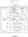
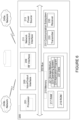
- Interface 190 is used in the wired or wireless communication of signalling and/or data between network node0, network 106, and/or wireless devices 110. As illustrated, interface 190 comprises port(s)/terminal(s) 194 to send and receive data, for example to and from network 106 over a wired connection. Interface 190 also includes radio front end circuitry 192 that may be coupled to, or in certain embodiments a part of, antenna 162. Radio front end circuitry 192 comprises filters 198 and amplifiers 196. Radio front end circuitry 192 may be connected to antenna 162 and processing circuitry 170. Radio front end circuitry may be configured to condition signals communicated between antenna 162 and processing circuitry 170.
- Radio front end circuitry 192 may receive digital data that is to be sent out to other network nodes or wireless devices via a wireless connection. Radio front end circuitry 192 may convert the digital data into a radio signal having the appropriate channel and bandwidth parameters using a combination of filters 198 and/or amplifiers 196. The radio signal may then be transmitted via antenna 162. Similarly, when receiving data, antenna 162 may collect radio signals which are then converted into digital data by radio front end circuitry 192. The digital data may be passed to processing circuitry 170. In other embodiments, the interface may comprise different components and/or different combinations of components.
- network node0 may not include separate radio front end circuitry 192, instead, processing circuitry 170 may comprise radio front end circuitry and may be connected to antenna 162 without separate radio front end circuitry 192.
- processing circuitry 170 may comprise radio front end circuitry and may be connected to antenna 162 without separate radio front end circuitry 192.
- all or some of RF transceiver circuitry 172 may be considered a part of interface 190.
- interface 190 may include one or more ports or terminals 194, radio front end circuitry 192, and RF transceiver circuitry 172, as part of a radio unit (not shown), and interface 190 may communicate with baseband processing circuitry 174, which is part of a digital unit (not shown).
- network node0 may include additional components beyond those shown in FIGURE 4 that may be responsible for providing certain aspects of the network node's functionality, including any of the functionality described herein and/or any functionality necessary to support the subject matter described herein.
- network node0 may include user interface equipment to allow input of information into network node0 and to allow output of information from network node0. This may allow a user to perform diagnostic, maintenance, repair, and other administrative functions for network node0.
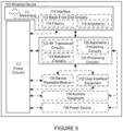
- FIGURE 5 illustrates an example wireless device 110.
- wireless device refers to a device capable, configured, arranged and/or operable to communicate wirelessly with network nodes and/or other wireless devices. Unless otherwise noted, the term wireless device may be used interchangeably herein with UE. Communicating wirelessly may involve transmitting and/or receiving wireless signals using electromagnetic waves, radio waves, infrared waves, and/or other types of signals suitable for conveying information through air.
- a wireless device may be configured to transmit and/or receive information without direct human interaction. For instance, a wireless device may be designed to transmit information to a network on a predetermined schedule, when triggered by an internal or external event, or in response to requests from the network.
- Examples of a wireless device include, but are not limited to, a smart phone, a mobile phone, a cell phone, a voice over IP (VoIP) phone, a wireless local loop phone, a desktop computer, a PDA, a wireless cameras, a gaming console or device, a music storage device, a playback appliance, a wearable terminal device, a wireless endpoint, a mobile station, a tablet, a laptop, a LEE, a ME), a smart device, a wireless CPE, a vehicle-mounted wireless terminal device, etc.
- VoIP voice over IP
- wireless device 110 includes antenna 111, interface 114, processing circuitry 120, device readable medium 130, user interface equipment 132, auxiliary equipment 134, power source 136 and power circuitry 137.
- Wireless device 110 may include multiple sets of one or more of the illustrated components for different wireless technologies supported by wireless device 110, such as, for example, GSM, WCDMA, LTE, NR, WiFi, WiMAX, or Bluetooth wireless technologies, just to mention a few. These wireless technologies may be integrated into the same or different chips or set of chips as other components within wireless device 110.
- interface 114 comprises radio front end circuitry 112 and antenna 111.
- Radio front end circuitry 112 comprise one or more filters 118 and amplifiers 116.
- Radio front end circuitry 112 is connected to antenna 111 and processing circuitry 120 and is configured to condition signals communicated between antenna 111 and processing circuitry 120.
- Radio front end circuitry 112 may be coupled to or a part of antenna 111.
- wireless device 110 may not include separate radio front end circuitry 112; rather, processing circuitry 120 may comprise radio front end circuitry and may be connected to antenna 111.
- some or all of RF transceiver circuitry 122 may be considered a part of interface 114.
- Processing circuitry 120 may comprise a combination of one or more of a microprocessor, controller, microcontroller, central processing unit, digital signal processor, application-specific integrated circuit, field programmable gate array, or any other suitable computing device, resource, or combination of hardware, software, and/or encoded logic operable to provide, either alone or in conjunction with other wireless device 110 components, such as device readable medium 130, wireless device 110 functionality. Such functionality may include providing any of the various wireless features or benefits discussed herein. For example, processing circuitry 120 may execute instructions stored in device readable medium 130 or in memory within processing circuitry 120 to provide the functionality disclosed herein.
- processing circuitry 120 includes one or more of RF transceiver circuitry 122, baseband processing circuitry 124, and application processing circuitry 126.
- the processing circuitry may comprise different components and/or different combinations of components.
- processing circuitry 120 of wireless device 110 may comprise a SOC.
- RF transceiver circuitry 122, baseband processing circuitry 124, and application processing circuitry 126 may be on separate chips or sets of chips.
- part or all of baseband processing circuitry 124 and application processing circuitry 126 may be combined into one chip or set of chips, and RF transceiver circuitry 122 may be on a separate chip or set of chips.
- part or all of RF transceiver circuitry 122 and baseband processing circuitry 124 may be on the same chip or set of chips, and application processing circuitry 126 may be on a separate chip or set of chips.
- part or all of RF transceiver circuitry 122, baseband processing circuitry 124, and application processing circuitry 126 may be combined in the same chip or set of chips.
- RF transceiver circuitry 122 may be a part of interface 114.
- RF transceiver circuitry 122 may condition RF signals for processing circuitry 120.
- Processing circuitry 120 may be configured to perform any determining, calculating, or similar operations (e.g., certain obtaining operations) described herein as being performed by a wireless device. These operations, as performed by processing circuitry 120, may include processing information obtained by processing circuitry 120 by, for example, converting the obtained information into other information, comparing the obtained information or converted information to information stored by wireless device 110, and/or performing one or more operations based on the obtained information or converted information, and as a result of said processing making a determination.
- processing information obtained by processing circuitry 120 by, for example, converting the obtained information into other information, comparing the obtained information or converted information to information stored by wireless device 110, and/or performing one or more operations based on the obtained information or converted information, and as a result of said processing making a determination.
- Device readable medium 130 may be operable to store a computer program, software, an application including one or more of logic, rules, code, tables, etc. and/or other instructions capable of being executed by processing circuitry 120.
- Device readable medium 130 may include computer memory (e.g., Random Access Memory (RAM) or Read Only Memory (ROM)), mass storage media (e.g., a hard disk), removable storage media (e.g., a Compact Disk (CD) or a Digital Video Disk (DVD)), and/or any other volatile or non-volatile, non-transitory device readable and/or computer executable memory devices that store information, data, and/or instructions that may be used by processing circuitry 120.
- processing circuitry 120 and device readable medium 130 may be considered to be integrated.
- User interface equipment 132 may provide components that allow for a human user to interact with wireless device 110. Such interaction may be of many forms, such as visual, audial, tactile, etc. User interface equipment 132 may be operable to produce output to the user and to allow the user to provide input to wireless device 110. The type of interaction may vary depending on the type of user interface equipment 132 installed in wireless device 110. For example, if wireless device 110 is a smart phone, the interaction may be via a touch screen; if wireless device 110 is a smart meter, the interaction may be through a screen that provides usage (e.g., the number of gallons used) or a speaker that provides an audible alert (e.g., if smoke is detected).
- usage e.g., the number of gallons used
- a speaker that provides an audible alert
- User interface equipment 132 may include input interfaces, devices and circuits, and output interfaces, devices and circuits. User interface equipment 132 is configured to allow input of information into wireless device 110 and is connected to processing circuitry 120 to allow processing circuitry 120 to process the input information. User interface equipment 132 may include, for example, a microphone, a proximity or other sensor, keys/buttons, a touch display, one or more cameras, a USB port, or other input circuitry. User interface equipment 132 is also configured to allow output of information from wireless device 110, and to allow processing circuitry 120 to output information from wireless device 110. User interface equipment 132 may include, for example, a speaker, a display, vibrating circuitry, a USB port, a headphone interface, or other output circuitry. Using one or more input and output interfaces, devices, and circuits, of user interface equipment 132, wireless device 110 may communicate with end users and/or the wireless network and allow them to benefit from the functionality described herein.
- Auxiliary equipment 134 is operable to provide more specific functionality which may not be generally performed by wireless devices. This may comprise specialized sensors for doing measurements for various purposes, interfaces for additional types of communication such as wired communications etc. The inclusion and type of components of auxiliary equipment 134 may vary depending on the embodiment and/or scenario.
- Power source 136 may, in some embodiments, be in the form of a battery or battery pack. Other types of power sources, such as an external power source (e.g., an electricity outlet), photovoltaic devices or power cells, may also be used.
- wireless device 110 may further comprise power circuitry 137 for delivering power from power source 136 to the various parts of wireless device 110 which need power from power source 136 to carry out any functionality described or indicated herein.
- Power circuitry 137 may in certain embodiments comprise power management circuitry.
- Power circuitry 137 may additionally or alternatively be operable to receive power from an external power source; in which case wireless device 110 may be connectable to the external power source (such as an electricity outlet) via input circuitry or an interface such as an electrical power cable.
- Power circuitry 137 may also in certain embodiments be operable to deliver power from an external power source to power source 136. This may be, for example, for the charging of power source 136. Power circuitry 137 may perform any formatting, converting, or other modification to the power from power source 136 to make the power suitable for the respective components of wireless device 110 to which power is supplied.
- FIGURE 6 illustrates one embodiment of a UE in accordance with various aspects described herein.
- a user equipment or UE may not necessarily have a user in the sense of a human user who owns and/or operates the relevant device.
- a UE may represent a device that is intended for sale to, or operation by, a human user but which may not, or which may not initially, be associated with a specific human user (e.g., a smart sprinkler controller).
- a UE may represent a device that is not intended for sale to, or operation by, an end user but which may be associated with or operated for the benefit of a user (e.g., a smart power meter).
- UE 200 may be any UE identified by the 3GPP, including a NB-IoT UE, a machine type communication (MTC) UE, and/or an enhanced MTC (eMTC) UE.
- UE 200 as illustrated in FIGURE 4 , is one example of a wireless device configured for communication in accordance with one or more communication standards promulgated by the 3GPP, such as 3GPP's GSM, UMTS, LTE, and/or 5G standards.
- 3GPP's GSM, UMTS, LTE, and/or 5G standards such as 3GPP's GSM, UMTS, LTE, and/or 5G standards.
- the term wireless device and UE may be used interchangeable. Accordingly, although FIGURE 6 is a UE, the components discussed herein are equally applicable to a wireless device, and vice-versa.
- UE 200 includes processing circuitry 201 that is operatively coupled to input/output interface 205, radio frequency (RF) interface 209, network connection interface 211, memory 215 including random access memory (RAM) 217, read-only memory (ROM) 219, and storage medium 221 or the like, communication subsystem 231, power source 233, and/or any other component, or any combination thereof.
- Storage medium 221 includes operating system 223, application program 225, and data 227. In other embodiments, storage medium 221 may include other similar types of information.
- Certain UEs may utilize all of the components shown in FIGURE 6 , or only a subset of the components. The level of integration between the components may vary from one UE to another UE. Further, certain UEs may contain multiple instances of a component, such as multiple processors, memories, transceivers, transmitters, receivers, etc.
- processing circuitry 201 may be configured to process computer instructions and data.
- Processing circuitry 201 may be configured to implement any sequential state machine operative to execute machine instructions stored as machine-readable computer programs in the memory, such as one or more hardware-implemented state machines (e.g., in discrete logic, FPGA, ASIC, etc.); programmable logic together with appropriate firmware; one or more stored program, general-purpose processors, such as a microprocessor or Digital Signal Processor (DSP), together with appropriate software; or any combination of the above.
- the processing circuitry 201 may include two central processing units (CPUs). Data may be information in a form suitable for use by a computer.
- input/output interface 205 may be configured to provide a communication interface to an input device, output device, or input and output device.
- UE 200 may be configured to use an output device via input/output interface 205.
- An output device may use the same type of interface port as an input device.
- a USB port may be used to provide input to and output from UE 200.
- the output device may be a speaker, a sound card, a video card, a display, a monitor, a printer, an actuator, an emitter, a smartcard, another output device, or any combination thereof.
- UE 200 may be configured to use an input device via input/output interface 205 to allow a user to capture information into UE 200.
- the input device may include a touch-sensitive or presence-sensitive display, a camera (e.g., a digital camera, a digital video camera, a web camera, etc.), a microphone, a sensor, a mouse, a trackball, a directional pad, a trackpad, a scroll wheel, a smartcard, and the like.
- the presence-sensitive display may include a capacitive or resistive touch sensor to sense input from a user.
- a sensor may be, for instance, an accelerometer, a gyroscope, a tilt sensor, a force sensor, a magnetometer, an optical sensor, a proximity sensor, another like sensor, or any combination thereof.
- the input device may be an accelerometer, a magnetometer, a digital camera, a microphone, and an optical sensor.
- RAM 217 may be configured to interface via bus 202 to processing circuitry 201 to provide storage or caching of data or computer instructions during the execution of software programs such as the operating system, application programs, and device drivers.
- ROM 219 may be configured to provide computer instructions or data to processing circuitry 201.
- ROM 219 may be configured to store invariant low-level system code or data for basic system functions such as basic input and output (I/O), startup, or reception of keystrokes from a keyboard that are stored in a non-volatile memory.
- Storage medium 221 may be configured to include memory such as RAM, ROM, programmable read-only memory (PROM), erasable programmable read-only memory (EPROM), electrically erasable programmable read-only memory (EEPROM), magnetic disks, optical disks, floppy disks, hard disks, removable cartridges, or flash drives.
- storage medium 221 may be configured to include operating system 223, application program 225 such as a web browser application, a widget or gadget engine or another application, and data file 227.
- Storage medium 221 may store, for use by UE 200, any of a variety of various operating systems or combinations of operating systems.
- Storage medium 221 may be configured to include a number of physical drive units, such as redundant array of independent disks (RAID), floppy disk drive, flash memory, USB flash drive, external hard disk drive, thumb drive, pen drive, key drive, high-density digital versatile disc (HD-DVD) optical disc drive, internal hard disk drive, Blu-Ray optical disc drive, holographic digital data storage (HDDS) optical disc drive, external mini-dual in-line memory module (DIMM), synchronous dynamic random access memory (SDRAM), external micro-DIMM SDRAM, smartcard memory such as a subscriber identity module or a removable user identity (SIM/RUIM) module, other memory, or any combination thereof.
- RAID redundant array of independent disks
- HD-DVD high-density digital versatile disc
- HDDS holographic digital data storage
- DIMM external mini-dual in-line memory module
- SDRAM synchronous dynamic random access memory
- SDRAM synchronous dynamic random access memory
- smartcard memory such as a subscriber identity module or a removable user
- Storage medium 221 may allow UE 200 to access computer-executable instructions, application programs or the like, stored on transitory or non-transitory memory media, to offload data, or to upload data.
- An article of manufacture, such as one utilizing a communication system may be tangibly embodied in storage medium 221, which may comprise a device readable medium.
- processing circuitry 201 may be configured to communicate with network 243b using communication subsystem 231.
- Network 243a and network 243b may be the same network or networks or different network or networks.
- Communication subsystem 231 may be configured to include one or more transceivers used to communicate with network 243b.
- communication subsystem 231 may be configured to include one or more transceivers used to communicate with one or more remote transceivers of another device capable of wireless communication such as another wireless device, UE, or base station of a radio access network (RAN) according to one or more communication protocols, such as IEEE 802.2, CDMA, WCDMA, GSM, LTE, UTRAN, WiMax, or the like.
- RAN radio access network
- Each transceiver may include transmitter 233 and/or receiver 235 to implement transmitter or receiver functionality, respectively, appropriate to the RAN links (e.g., frequency allocations and the like). Further, transmitter 233 and receiver 235 of each transceiver may share circuit components, software or firmware, or alternatively may be implemented separately.
- the communication functions of communication subsystem 231 may include data communication, voice communication, multimedia communication, short-range communications such as Bluetooth, near-field communication, location-based communication such as the use of the global positioning system (GPS) to determine a location, another like communication function, or any combination thereof.
- communication subsystem 231 may include cellular communication, Wi-Fi communication, Bluetooth communication, and GPS communication.
- Network 243b may encompass wired and/or wireless networks such as a local-area network (LAN), a wide-area network (WAN), a computer network, a wireless network, a telecommunications network, another like network or any combination thereof.
- network 243b may be a cellular network, a Wi-Fi network, and/or a near-field network.
- Power source 213 may be configured to provide alternating current (AC) or direct current (DC) power to components of UE 200.
- communication subsystem 231 may be configured to include any of the components described herein.
- processing circuitry 201 may be configured to communicate with any of such components over bus 202.
- any of such components may be represented by program instructions stored in memory that when executed by processing circuitry 201 perform the corresponding functions described herein.
- the functionality of any of such components may be partitioned between processing circuitry 201 and communication subsystem 231.
- the non-computationally intensive functions of any of such components may be implemented in software or firmware and the computationally intensive functions may be implemented in hardware.
- FIGURE 7 is a schematic block diagram illustrating a virtualization environment 300 in which functions implemented by some embodiments may be virtualized.
- virtualizing means creating virtual versions of apparatuses or devices which may include virtualizing hardware platforms, storage devices and networking resources.
- virtualization can be applied to a node (e.g., a virtualized base station or a virtualized radio access node) or to a device (e.g., a UE, a wireless device or any other type of communication device) or components thereof and relates to an implementation in which at least a portion of the functionality is implemented as one or more virtual components (e.g., via one or more applications, components, functions, virtual machines or containers executing on one or more physical processing nodes in one or more networks).
- a node e.g., a virtualized base station or a virtualized radio access node
- a device e.g., a UE, a wireless device or any other type of communication device
- some or all of the functions described herein may be implemented as virtual components executed by one or more virtual machines implemented in one or more virtual environments 300 hosted by one or more of hardware nodes 330. Further, in embodiments in which the virtual node is not a radio access node or does not require radio connectivity (e.g., a core network node), then the network node may be entirely virtualized.
- the virtual node is not a radio access node or does not require radio connectivity (e.g., a core network node)
- the network node may be entirely virtualized.
- the functions may be implemented by one or more applications 320 (which may alternatively be called software instances, virtual appliances, network functions, virtual nodes, virtual network functions, etc.) operative to implement some of the features, functions, and/or benefits of some of the embodiments disclosed herein.
- Applications 320 are run in virtualization environment 300 which provides hardware 330 comprising processing circuitry 360 and memory 390.
- Memory 390 contains instructions 395 executable by processing circuitry 360 whereby application 320 is operative to provide one or more of the features, benefits, and/or functions disclosed herein.
- Virtualization environment 300 comprises general-purpose or special-purpose network hardware devices 330 comprising a set of one or more processors or processing circuitry 360, which may be commercial off-the-shelf (COTS) processors, dedicated Application Specific Integrated Circuits (ASICs), or any other type of processing circuitry including digital or analog hardware components or special purpose processors.
- processors or processing circuitry 360 which may be commercial off-the-shelf (COTS) processors, dedicated Application Specific Integrated Circuits (ASICs), or any other type of processing circuitry including digital or analog hardware components or special purpose processors.
- Each hardware device may comprise memory 390-1 which may be non-persistent memory for temporarily storing instructions 395 or software executed by processing circuitry 360.
- Each hardware device may comprise one or more network interface controllers (NICs) 370, also known as network interface cards, which include physical network interface 380.
- NICs network interface controllers
- Each hardware device may also include non-transitory, persistent, machine-readable storage media 390-2 having stored therein software 395 and/or instructions executable by processing circuitry 360.
- Software 395 may include any type of software including software for instantiating one or more virtualization layers 350 (also referred to as hypervisors), software to execute virtual machines 340 as well as software allowing it to execute functions, features and/or benefits described in relation with some embodiments described herein.
- Virtual machines 340 comprise virtual processing, virtual memory, virtual networking or interface and virtual storage, and may be run by a corresponding virtualization layer 350 or hypervisor. Different embodiments of the instance of virtual appliance 320 may be implemented on one or more of virtual machines 340, and the implementations may be made in different ways.
- processing circuitry 360 executes software 395 to instantiate the hypervisor or virtualization layer 350, which may sometimes be referred to as a virtual machine monitor (VMM).
- VMM virtual machine monitor
- Virtualization layer 350 may present a virtual operating platform that appears like networking hardware to virtual machine 340.
- hardware 330 may be a standalone network node with generic or specific components. Hardware 330 may comprise antenna 3225 and may implement some functions via virtualization. Alternatively, hardware 330 may be part of a larger cluster of hardware (e.g. such as in a data center or customer premise equipment (CPE)) where many hardware nodes work together and are managed via management and orchestration (MANO) 3100, which, among others, oversees lifecycle management of applications 320.
- CPE customer premise equipment
- MANO management and orchestration
- NFV network function virtualization
- NFV may be used to consolidate many network equipment types onto industry standard high volume server hardware, physical switches, and physical storage, which can be located in data centers, and customer premise equipment.
- virtual machine 340 may be a software implementation of a physical machine that runs programs as if they were executing on a physical, non-virtualized machine.
- Each of virtual machines 340, and that part of hardware 330 that executes that virtual machine be it hardware dedicated to that virtual machine and/or hardware shared by that virtual machine with others of the virtual machines 340, forms a separate virtual network elements (VNE).
- VNE virtual network elements
- VNF Virtual Network Function
- one or more radio units 3200 that each include one or more transmitters 3220 and one or more receivers 3210 may be coupled to one or more antennas 3225.
- Radio units 3200 may communicate directly with hardware nodes 330 via one or more appropriate network interfaces and may be used in combination with the virtual components to provide a virtual node with radio capabilities, such as a radio access node or a base station.
- control system 3230 which may alternatively be used for communication between the hardware nodes 330 and radio units 3200.
- FIGURE 8 illustrates a telecommunication network connected via an intermediate network to a host computer in accordance with some embodiments.
- OTT connection 550 has been drawn abstractly to illustrate the communication between host computer 510 and UE 530 via base station 520, without explicit reference to any intermediary devices and the precise routing of messages via these devices.
- Network infrastructure may determine the routing, which it may be configured to hide from UE 530 or from the service provider operating host computer 510, or both. While OTT connection 550 is active, the network infrastructure may further take decisions by which it dynamically changes the routing (e.g., on the basis of load balancing consideration or reconfiguration of the network).
- Wireless connection 570 between UE 530 and base station 520 is in accordance with the teachings of the embodiments described throughout this disclosure.
- One or more of the various embodiments improve the performance of OTT services provided to UE 530 using OTT connection 550, in which wireless connection 570 forms the last segment. More precisely, the teachings of these embodiments may improve the data rate, latency, and/or power consumption and thereby provide benefits such as reduced user waiting time, relaxed restriction on file size, better responsiveness, and/or extended battery lifetime.
- a measurement procedure may be provided for the purpose of monitoring data rate, latency and other factors on which the one or more embodiments improve.
- the measurement procedure and/or the network functionality for reconfiguring OTT connection 550 may be implemented in software 511 and hardware 515 of host computer 510 or in software 531 and hardware 535 of UE 530, or both.
- sensors (not shown) may be deployed in or in association with communication devices through which OTT connection 550 passes; the sensors may participate in the measurement procedure by supplying values of the monitored quantities exemplified above or supplying values of other physical quantities from which software 511, 531 may compute or estimate the monitored quantities.
- the reconfiguring of OTT connection 550 may include message format, retransmission settings, preferred routing etc.; the reconfiguring need not affect base station 520, and it may be unknown or imperceptible to base station 520. Such procedures and functionalities may be known and practiced in the art.
- measurements may involve proprietary UE signaling facilitating host computer 510's measurements of throughput, propagation times, latency and the like.
- the measurements may be implemented in that software 511 and 531 causes messages to be transmitted, in particular empty or 'dummy' messages, using OTT connection 550 while it monitors propagation times, errors etc.
- step 630 the base station transmits to the UE the user data which was carried in the transmission that the host computer initiated, in accordance with the teachings of the embodiments described throughout this disclosure.
- step 640 the UE executes a client application associated with the host application executed by the host computer.
- IGURE 11 is a flowchart illustrating a method implemented in a communication system, in accordance with one embodiment.
- the communication system includes a host computer, a base station and a UE which may be those described with reference to FIGURES 8 and 9 .
- the host computer provides user data.
- the host computer provides the user data by executing a host application.
- the host computer initiates a transmission carrying the user data to the UE.
- the transmission may pass via the base station, in accordance with the teachings of the embodiments described throughout this disclosure.
- step 730 (which may be optional), the UE receives the user data carried in the transmission.
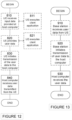
- FIGURE 12 is a flowchart illustrating a method implemented in a communication system, in accordance with one embodiment.
- the communication system includes a host computer, a base station and a UE which may be those described with reference to FIGURES 8 and 9 .
- the UE receives input data provided by the host computer.
- the UE provides user data.
- substep 821 (which may be optional) of step 820, the UE provides the user data by executing a client application.
- substep 811 (which may be optional) of step 810, the UE executes a client application which provides the user data in reaction to the received input data provided by the host computer.
- the executed client application may further consider user input received from the user.
- the UE initiates, in substep 830 (which may be optional), transmission of the user data to the host computer.
- step 840 of the method the host computer receives the user data transmitted from the UE, in accordance with the teachings of the embodiments described throughout this disclosure.
- FIGURE 13 is a flowchart illustrating a method implemented in a communication system, in accordance with one embodiment.
- the communication system includes a host computer, a base station and a UE which may be those described with reference to FIGURES 8 and 9 .
- the base station receives user data from the UE.
- the base station initiates transmission of the received user data to the host computer.
- the host computer receives the user data carried in the transmission initiated by the base station.
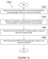
- FIGURE 14 depicts a method 1000 by a wireless device 110, according to certain embodiments.
- the wireless device monitors or not monitors a PDCCH.
- the wireless device receives an indication to transition from the first PDCCH monitoring state to a second PDCCH monitoring state.
- the wireless device transitions from the first PDCCH monitoring state to the second PDCCH monitoring state.
- the wireless device monitors or not monitors the PDCCH.
- the method may additionally or alternatively include one or more of the steps or features of the Group A, Group C, and Group E Example Embodiments described below.
- FIGURE 15 illustrates a schematic block diagram of a virtual apparatus 1100 in a wireless network (for example, the wireless network shown in FIGURE 3 ).
- the apparatus may be implemented in a wireless device or network node (e.g., wireless device 110 or network node0 shown in FIGURE 3 ).
- Apparatus 1100 is operable to carry out the example method described with reference to FIGURE 14 and possibly any other processes or methods disclosed herein. It is also to be understood that the method of FIGURE 14 is not necessarily carried out solely by apparatus 1100. At least some operations of the method can be performed by one or more other entities.
- Virtual Apparatus 1100 may comprise processing circuitry, which may include one or more microprocessor or microcontrollers, as well as other digital hardware, which may include digital signal processors (DSPs), special-purpose digital logic, and the like.
- the processing circuitry may be configured to execute program code stored in memory, which may include one or several types of memory such as read-only memory (ROM), random-access memory, cache memory, flash memory devices, optical storage devices, etc.
- Program code stored in memory includes program instructions for executing one or more telecommunications and/or data communications protocols as well as instructions for carrying out one or more of the techniques described herein, in several embodiments.
- the processing circuitry may be used to cause first monitoring module 1110, receiving module 1120, transitioning module 1130, second monitoring module M40, and any other suitable units of apparatus 1100 to perform corresponding functions according one or more embodiments of the present disclosure.
- first monitoring module 1110 may perform certain of the monitoring functions of the apparatus 1100. For example, first monitoring module 1110 may monitor or not monitor the PDCCH while in a first PDCCH monitoring state.
- receiving module 1120 may perform certain of the receiving functions of the apparatus 1100. For example, receiving module 1120 may receive an indication to transition from the first PDCCH monitoring state to a second PDCCH monitoring state.
- transitioning module 1130 may perform certain of the transitioning functions of the apparatus 1100. For example, transitioning module 1130 may transition from the first PDCCH monitoring state to the second PDCCH monitoring state.
- second monitoring module 1140 may perform certain of the monitoring functions of the apparatus 1100. For example, second monitoring module 1140 may monitor monitors or not monitors the PDCCH while in the second PDCCH monitoring state.
- virtual apparatus may additionally include one or more modules for performing any of the steps or providing any of the features in the Group A, Group C, and Group E Example Embodiments described below.
- module or unit may have conventional meaning in the field of electronics, electrical devices and/or electronic devices and may include, for example, electrical and/or electronic circuitry, devices, modules, processors, memories, logic solid state and/or discrete devices, computer programs or instructions for carrying out respective tasks, procedures, computations, outputs, and/or displaying functions, and so on, as such as those that are described herein.
- FIGURE 16 depicts a method 1200 by a network node0, according to certain embodiments.
- the network node transmits, to a wireless device, an indication to transition the wireless device from a first PDCCH monitoring state for monitoring a PDCCH to a second PDCCH monitoring state for monitoring the PDCCH.
- the method may include one or more of any of the steps or features of the Group B, Group D, and Group E Example Embodiments described below.
- FIGURE 17 illustrates a schematic block diagram of a virtual apparatus 1300 in a wireless network (for example, the wireless network shown in FIGURE 3 ).
- the apparatus may be implemented in a wireless device or network node (e.g., wireless device 110 or network node0 shown in FIGURE 3 ).
- Apparatus 1300 is operable to carry out the example method described with reference to FIGURE 16 and possibly any other processes or methods disclosed herein. It is also to be understood that the method of FIGURE 16 is not necessarily carried out solely by apparatus 1300. At least some operations of the method can be performed by one or more other entities.
- Virtual Apparatus 1300 may comprise processing circuitry, which may include one or more microprocessor or microcontrollers, as well as other digital hardware, which may include digital signal processors (DSPs), special-purpose digital logic, and the like.
- the processing circuitry may be configured to execute program code stored in memory, which may include one or several types of memory such as read-only memory (ROM), random-access memory, cache memory, flash memory devices, optical storage devices, etc.
- Program code stored in memory includes program instructions for executing one or more telecommunications and/or data communications protocols as well as instructions for carrying out one or more of the techniques described herein, in several embodiments.
- the processing circuitry may be used to cause transmitting module 1310 and any other suitable units of apparatus 1300 to perform corresponding functions according one or more embodiments of the present disclosure.
- transmitting module 1310 may perform certain of the transmitting functions of the apparatus 1300. For example, transmitting module 1310 may transmit, to a wireless device, an indication to transition the wireless device from a first PDCCH monitoring state for monitoring a PDCCH to a second PDCCH monitoring state for monitoring the PDCCH.
- virtual apparatus may additionally include one or more modules for performing any of the steps or providing any of the features in the Group B, Group D, and Group E Example Embodiments described below.
- DCCH monitoring is one contributing factor to wireless device power consumption in cellular systems such as system based on 3GPP 5 th Generation (5G, also referred to as NR) wireless communication standards.
- DRX is an important mechanism that allows reduction in wireless device power consumption by allowing the wireless device to sleep (e.g., go to DRX which may reduce/omit PDCCH monitoring) or to monitor PDCCH based during "active time,” etc.
- Active time typically includes the time duration when a DRX ON duration timer and/or a DRX Inactivity timer is running, and in which the wireless device monitors PDCCH. Since packet inter-arrival time is typically an unknown quantity, to avoid unnecessary packet delays, it may be preferable to let a wireless device monitor PDCCH for a certain duration after receiving a packet (e.g., to receive a future packet), rather than allowing the wireless device to immediately go to sleep. This is achieved using the Inactivity timer (IAT) which can be set to a reasonably large value (e.g., 200ms for a DRX cycle of length 320ms) and allows the wireless device to be awake for a certain duration after receiving a packet. However, use of the IAT can also lead to increased power consumption especially when the IAT value is very large.
- IAT Inactivity timer
- PDCCH search space set (SS) group switching also referred to as search space set switching
- PDCCH skipping PDCCH skipping
- Two groups of search space sets for a cell can be configured in 3GPP Release (Rel)-16. If configured (through the RRC parameters searchSpaceGroupIdList-r 16 and searchSpaceSwitchingGroup-r16), then the wireless device can be switched between these two groups of search space sets using either explicit or implicit mechanisms. Some search spaces may not appear in the search space sets. Such search spaces can be always and/or continuously monitored, and monitoring of such search spaces is not impacted by the search space set switching mechanism.
- the wireless device can be switched between the two search space groups through detection of a DCI format 2_0. This is performed by configuring the wireless device with the RRC parameter searchSpaceSwitchTrigger-r16 which provides a location for the search space set group switching field (for a serving cell) in the DCI format 2_0.
- the search-space-set- switching field is one bit in size, where a bit value of zero indicates one group and a value of one indicates the second group. We refer to these two groups by group0 and group 1, where the search-space-set-switching field takes the values zero and one, respectively.
- Implicit switching occurs when the wireless device is not configured with the RRC searchSpaceSwitchTrigger-r16 parameter.
- the procedure is as follows:
- a wireless device can be configured with up to 10 search space sets per cell.
- Cell groups are defined for SS set switching such that if SS switching is triggered for one cell in the group of cells, it also triggers SS switching for all cells in the corresponding group.
- up to four groups of cells can be supported, and these can be indicated using DCI format 2_0.
- the search space set switching triggering indication can also be provided in scheduling DCI such as DCI 1-1 that schedules downlink data (e.g., PDSCH) or DCI 0-1 that can schedule uplink data (e.g., PUSCH).
- DCI 1-1 that schedules downlink data
- DCI 0-1 that can schedule uplink data (e.g., PUSCH).
- the wireless device can be configured with a bitfield within one of the scheduling DCIs to indicate a duration during which the wireless device can skip decoding of PDCCH.
- the wireless device can be configured with a time duration of 4ms, and when the PDCCH skipping bit within a DCI is set to 1, the wireless device can skip PDCCH monitoring for next 4 ms.
- the wireless device may skip PDCCH monitoring for a particular set of search spaces and RNTIs, for example, the wireless device may skip monitoring of all wireless device-specific search space sets, and/or monitoring of wireless device-specific RNTIs, such as C-RNTI, CS-RNTI, etc.
- Some embodiments advantageously provide methods, systems, and apparatuses for modification of physical downlink control channel (PDCCH) monitoring.
- PDCCH physical downlink control channel
- a method of joint L1 indication of search space set switching and PDCCH skipping is described herein. Also described herein is a method of efficient control of the PDCCH monitoring adaption when the wireless device is configured with carrier aggregation, as well as for cases when the wireless device is configured with dormant BWP for some SCells and search space set switching for some SCells.
- existing systems lack methods to efficiently combine the search-space set group switching and PDCCH skipping framework for a given wireless device, especially when the wireless device is configured multiple carriers in a carrier aggregation scenario.
- the present disclosure advantageously solves at least a portion of the problems with existing systems by providing methods and mechanisms to provide the wireless device with the opportunity to reduce PDCCH monitoring during active time of C-DRX using both search-space set group switching and PDCCH skipping mechanisms, thereby achieving power savings.
- One or more embodiments described herein also reduce the PDCCH resources at the network node side e.g., by allowing the network node to indicate PDCCH monitoring adaptions for a group of cells in an efficient manner.
- one or more embodiments described herein provide the network node with the flexibility to choose flexibly between search space set group switching or PDCCH skipping depending on the traffic situation, data arrival patterns, latency, etc.
- Coupled may be used herein to indicate a connection, although not necessarily directly, and may include wired and/or wireless connections.
- network node can be any kind of network node comprised in a radio network which may further comprise any of base station (BS), radio base station, base transceiver station (BTS), base station controller (BSC), radio network controller (RNC), g Node B (gNB), evolved Node B (eNB or eNodeB), Node B, multi-standard radio (MSR) radio node such as MSR BS, multi-cell/multicast coordination entity (MCE), integrated access and backhaul (IAB) node, relay node, donor node controlling relay, radio access point (AP), transmission points, transmission nodes, Remote Radio Unit (RRU) Remote Radio Head (RRH), a core network node (e.g., mobile management entity (MME), self-organizing network (SON) node, a coordinating node, positioning node, MDT node, etc.), an external node (e.g., 3rd party node, a node external to the current network), nodes in distributed antenna system (
- BS base station
- wireless device or a user equipment (UE) are used interchangeably.
- the WD herein can be any type of wireless device capable of communicating with a network node or another WD over radio signals, such as wireless device (WD).
- the WD may also be a radio communication device, target device, device to device (D2D) WD, machine type WD or WD capable of machine to machine communication (M2M), low-cost and/or low-complexity WD, a sensor equipped with WD, Tablet, mobile terminals, smart phone, laptop embedded equipped (LEE), laptop mounted equipment (LME), USB dongles, Customer Premises Equipment (CPE), an Internet of Things (IoT) device, or a Narrowband IoT (NB-IOT) device, etc.
- D2D device to device
- M2M machine to machine communication
- M2M machine to machine communication
- Tablet mobile terminals
- smart phone laptop embedded equipped (LEE), laptop mounted equipment (LME), USB dongles
- CPE Customer Premises Equipment
- IoT Internet of Things
- NB-IOT Narrowband IoT
- radio network node can be any kind of a radio network node which may comprise any of base station, radio base station, base transceiver station, base station controller, network controller, RNC, evolved Node B (eNB), Node B, gNB, Multi-cell/multicast Coordination Entity (MCE), IAB node, relay node, access point, radio access point, Remote Radio Unit (RRU) Remote Radio Head (RRH).
- RNC evolved Node B
- MCE Multi-cell/multicast Coordination Entity
- IAB node IAB node
- relay node relay node
- access point radio access point
- RRU Remote Radio Unit
- RRH Remote Radio Head
- a cell may be generally a communication cell, e.g., of a cellular or mobile communication network, provided by a node.
- a serving cell may be a cell on or via which a network node (the node providing or associated to the cell, e.g., base station, gNB or eNodeB) transmits and/or may transmit data (which may be data other than broadcast data) to a user equipment, in particular control and/or user or payload data, and/or via or on which a user equipment transmits and/or may transmit data to the node;
- a serving cell may be a cell for or on which the user equipment is configured and/or to which it is synchronized and/or has performed an access procedure, e.g., a random access procedure, and/or in relation to which it is in a RRC_connected or RRC_idle state, e.g., in case the node and/or user equipment and/or network follow the LTE-standard.
- One or more carriers e.
- Transmitting in downlink may pertain to transmission from the network or network node to the wireless device.
- Transmitting in uplink may pertain to transmission from the wireless device to the network or network node.
- Transmitting in sidelink may pertain to (direct) transmission from one wireless device to another.
- Uplink, downlink and sidelink (e.g., sidelink transmission and reception) may be considered communication directions.
- uplink and downlink may also be used to described wireless communication between network nodes, e.g. for wireless backhaul and/or relay communication and/or (wireless) network communication for example between base stations or similar network nodes, in particular communication terminating at such. It may be considered that backhaul and/or relay communication and/or network communication is implemented as a form of sidelink or uplink communication or similar thereto.
- Configuring a terminal or wireless device or node may involve instructing and/or causing the wireless device or node to change its configuration, e.g., PDCCH monitoring configuration.
- a terminal or wireless device or node may be adapted to configure itself, e.g., according to information or data in a memory of the terminal or wireless device.
- Configuring a node or terminal or wireless device by another device or node or a network may refer to and/or comprise transmitting information and/or data and/or instructions to the wireless device or node by the other device or node or the network such as via a bitfield described herein.
- Configuring a terminal may include sending configuration data to the terminal indicating which modulation and/or encoding to use.
- WCDMA Wide Band Code Division Multiple Access
- WiMax Worldwide Interoperability for Microwave Access
- UMB Ultra Mobile Broadband
- GSM Global System for Mobile Communications
- functions described herein as being performed by a wireless device or a network node may be distributed over a plurality of wireless devices and/or network nodes.
- the functions of the network node and wireless device described herein are not limited to performance by a single physical device and, in fact, can be distributed among several physical devices.
- FIGURE 20 is a flowchart of an example process 1600 in a network node0 according to some embodiments of the present disclosure.
- One or more Blocks and/or functions performed by network node0 may be performed by one or more elements of network node0 such as by indication unit in processing circuitry, processor, radio interface, etc.
- network node such as via one or more of processing circuitry, processor, indication unit, communication interface and radio interface is configured to configure (1602) an indication for modifying physical downlink control channel, PDCCH, monitoring using at least one of search space set group switching and PDCCH skipping, as described herein.
- network node such as via one or more of processing circuitry 68, processor 70, indication unit 32, communication interface 60 and radio interface 62 is configured to cause transmission (1604) of the indication to the wireless device, as described herein.
- the indication is a bitfield that indicates performing both the search space set group switching and PDCCH skipping.
- the bitfield is configured to control at least one of search space set group switching and PDCCH skipping for at least one group of cells.
- the bitfield is configured to control at least one of search space set group switching and PDCCH skipping for a first group of cells and separately for a second group of cells.
- the bitfield is one of a PDCCH monitoring adaptation bitfield and cell group indication bitfield.
- FIGURE 21 is a flowchart of an example process 1700 in a wireless device 110 according to some embodiments of the present disclosure.
- One or more Blocks and/or functions performed by wireless device may be performed by one or more elements of wireless device such as by modification unit in processing circuitry 84, processor, radio interface, etc.
- wireless device such as via one or more of processing circuitry, processor, modification unit and radio interface is configured to receive (1702) an indication for modifying physical downlink control channel, PDCCH, monitoring using at least one of search space set group switching and PDCCH skipping, as described herein.
- wireless device such as via one or more of processing circuitry, processor 86, modification unit and radio interface is configured to modify (1704) the PDCCH monitoring based on the indication, as described herein.
- the indication is a bitfield that indicates performing both the search space set group switching and PDCCH skipping.
- the bitfield is configured to control at least one of search space set group switching and PDCCH skipping for at least one group of cells.
- the bitfield is configured to control at least one of search space set group switching and PDCCH skipping for a first group of cells and separately for a second group of cells.
- the bitfield is one of a PDCCH monitoring adaptation bitfield and cell group indication bitfield.
- Some embodiments provide modifying of PDCCH monitoring. Arrangements for joint control of search space set group switching and PDCCH skipping are described in detail herein. Note that when reference to DRX is made herein, this reference may include at least connected mode DRX (C-DRX). Such a DRX configuration typically includes an ON duration timer value, an inactivity timer value, and a long or short DRX cycle. In cases where short DRX cycle is configured, the configuration may additionally include a short DRX timer value.
- C-DRX connected mode DRX
- a wireless device is configured with DRX, and with at least one primary cell that may be provided by network node.
- the wireless device can be configured with one or more secondary cells that may be provided by the network node and/or another network node.
- Wireless device can be configured with at least two search space set groups for at least one cell.
- Wireless device can be further configured with a skip duration for the at least one cell.
- Wireless device such as via one or more of processing circuitry, processor, radio interface, modification unit, etc., can be configured to monitor a downlink control information on at least one cell containing at least a bitfield that can take field values indicating the wireless device to monitor PDCCH according to a first search space set group (SSSG#0), or to monitor PDCCH according to a second search space set group (SSG#1), and to skip PDCCH monitoring for a duration indicated by the higher layers, or pre-configured, e.g., in standardization documentations such as in 3GPP.
- the bitfield can be referred to as PDCCH monitoring adaptation bitfield.
- bitfield An example of the bitfield is shown in below in TABLE 1.
- the bitfield has 2 bits.
- the four resulting states can each indicate different wireless device behavior regarding PDCCH monitoring adaptation.
- the field value 01 can indicate that the wireless device start to monitor PDCCH according to search space sets in SSSG#0 (and stop PDCCH according to search space sets in SSSG#1).
- the field value can indicate that the wireless device such as via one or more of processing circuitry, processor, radio interface, modification unit, etc., start to monitor PDCCH according to search space sets in SSSG#1 (and stop PDCCH according to search space sets in SSSG#0).
- the field value indicate for wireless device such as via one or more of processing circuitry, processor, radio interface, modification unit, etc., skipping PDCCH monitoring for a time duration given by the skip duration.
- the field value 00 can indicate "reserved", for example to indicate that there is no change to wireless device's behavior with respect to PDCCH monitoring.
- the downlink control information containing the bitfield (e.g., PDCCH monitoring adaptation bitfield) is received by wireless device on a first serving cell, and the corresponding PDCCH monitoring adaptation is applicable for PDCCH monitoring on the first serving cell.
- the DCI bitfield is configured explicitly through higher layer signaling, e.g., RRC signaling, such as by network node.
- RRC signaling such as by network node.
- the associated DCI may be a non-fallback scheduling DCI format 0-1, 1-1, 1-2, or 0-2.
- wireless device can be configured through RRC signaling such as by network node with the PDCCH monitoring adaptation bitfield, and furthermore through RRC signaling, wireless device can be configured if one or all the specific indications are configured.
- the network node such as via one or more of processing circuitry, processor, radio interface, indication unit, etc. may only configure PDCCH skipping and not SS switching on a first serving cell, and thus network node only configures wireless device with the bitfield associated with PDCCH skipping.
- network node such as via one or more of processing circuitry, processor, radio interface, indication unit, etc., may configure PDCCH skipping and SS switching on a second serving cell, and thus wireless device is configured with all the indications mentioned in example above with respect to the configured bitfield.
- network node such as via one or more of processing circuitry, processor, radio interface, indication unit, etc., can configure the PDCCH monitoring adaptation bitfield in the same manner for all the valid DCIs, or to configure the bitfield individually for each valid DCI.
- network node such as via one or more of processing circuitry, processor, radio interface, indication unit, etc., may configure the PDCCH monitoring adaptation bitfield in DCI formats 1-1 and 0-1, and not in DCI format 1-2 or 0-2, since these two DCIs may be used for latency sensitive application.
- network node such as via one or more of processing circuitry, processor, radio interface, indication unit, etc., may configure all the fields in the adaptation bitfield for DCI formats 1-1 and 0-1, but may not configure PDCCH skipping for DCI formats 1-2 and 0-2, for example to avoid skipping PDCCH for latency sensitive applications.
- the wireless device can be configured with the PDCCH monitoring adaption bitfield by pre-configuration or a combination of pre-configuration and higher layer signaling from network node. For example, if wireless device such as via one or more of processing circuitry, processor, radio interface, modification unit, etc., receives a first configuration which meets a first condition, wireless device may then configure the PDCCH monitoring adaptation bitfield, or if the first configuration meets a second condition, then wireless device configures a subset of PDCCH monitoring bitfield and consider the rest as reserved or no change. In one example of this embodiment, wireless device is configured such as by network node with one or more search spaces (SSs) as the first configuration.
- SSs search spaces
- wireless device may assume the PDCCH monitoring adaptation field is present in the DCIs associated to the SSs, or all the potential DCIs which can be used for SS switching/PDCCH skipping.
- wireless device can be further configured with the skip PDCCH monitoring indication field also or to consider it as reserved if received.
- the wireless device may not be configured with search space set groups, but receives an indication from the higher layers configuring the PDCCH skipping indication in the PDCCH monitoring adaptation bitfield. In this case, wireless device consider the search space set group switching bitfield either as reserved or no change.
- network node may not transmit the PDCCH monitoring adaption bitfield even if configured.
- the wireless device such as via one or more of processing circuitry, processor, radio interface, modification unit, etc., receives a first DCI containing the monitoring adaptation bitfield, and thus the wireless device follows the indication in the DCI.
- wireless device such as via one or more of processing circuitry, processor 86, radio interface, modification unit, etc., receives a second DCI which could potentially include the bitfield as well, but wireless device does not receive the bitfield.
- wireless device behavior can be either configured by higher layer signaling from network node, or pre-configured such as by the network or network node. For example, if wireless device does not receive the PDCCH monitoring adaptation bitfield in a second DCI, then wireless device does not make any change, or wireless device follows a configured behavior, e.g., falling back to the first search space set group.
- the PDCCH monitoring adaptation can be further enhanced as described below.
- Wireless device can be configured with multiple serving cells such as cells belonging to frequency range 1 and/or frequency range 2 (FR1/FR2).
- the PDCCH monitoring adaptation can be configured such that a group of cells can be controlled using a single field.
- wireless device can be configured with a first group of cells, and a second group of cells, and the PDCCH monitoring adaptation can be configured and controlled individually for each group of the two group of cells.
- Wireless device can be configured to monitor a downlink control information on at least one cell containing at least a bitfield that can take field values indicating for wireless device to monitor PDCCH according to a first search space set group on the first group of cells, and to monitor PDCCH according to a second search space set group on the first group of cells, and to skip PDCCH monitoring on the first group of cells for a duration indicated by the higher layers.
- Wireless device such as via one or more of processing circuitry, processor 86, radio interface, modification unit, etc., detects a downlink control information, determines whether to monitor PDCCH and determines the search spaces to monitor based on the detected DCI, and monitors downlink control channel accordingly, and receives a downlink message in the downlink control channel.
- the DCI transmitted by, for example, network node can contain at least a second bitfield that can take field values indicating for wireless device to monitor PDCCH according to a first search space set group on the second group of cells, and to monitor PDCCH according to a second search space set group on the second group of cells, and to skip PDCCH monitoring on the second group of cells for a duration indicated by the higher layers.
- wireless device can be configured with a first grouping of cells for the search-space set group switching and a second grouping of cells for the PDCCH skipping. For example, if wireless device has/is configured with four cells (c0,c1,c2,c3), then for search space set group switching, the first group can comprise c0, and the second group can comprise c1,c2,c3, while for PDCCH skipping, the first group can include c0,c1, and the second group can comprise c2,c3.
- FIGURE 22 An example DCI format is shown in FIGURE 22 where different bitfields are configured in a DCI to control PDCCH monitoring adaptation for different cells.
- FIGURE 22 illustrates three different bitfields (CG0, CG1, CG2) to control search space set group switching and/or PDCCH skipping for three different groups of cells.
- Each field CG0 can control search space set group switching and/or PDCCH skipping for a group of cells configured by higher layers. For example, if wireless device is configured with FR1-FR2 carrier aggregation, a first cell group CG0 may contain the primary cell, a second cell group may contain the secondary serving cells belonging to FR1, and a third cell group may contain the secondary serving cells belonging to FR2.
- Each field (e.g., CG0) corresponding to each group (first group of cells) can indicate four values for each group of cells, as shown in below in TABLE 2.
- TABLE 2 PDCCH Monitoring adaptation bit field value WD behavior 00 No change or 'reserved' for the group of cells 01 Monitor SSSG#0 for the group of cells 10 Monitor SSSG#1 for the group of cells 11 Skip PDCCH monitoring for a skip duration for the group of cells
- wireless device can be configured with a first group of cells, and a second group of cells associated with search space set group switching.
- Wireless device can be configured with a third group of cells to skip PDCCH monitoring.
- the third group of cells includes all serving cells configured for wireless device.
- the wireless device such as via one or more of processing circuitry, processor, radio interface, modification unit, etc., can receive a configuration from higher layers that a first, a second and a third bitfields associated with a first, a second and a third group of cells is configured, and further, the higher layer signaling can indicate the starting location of each bitfield or their length (in case the length of the bitfields are configurable or different).
- the first, second and third bitfields may each be considered a PDDCH monitoring adaptation bitfield or may be considered to be part of the overall PDCCH monitoring adaption bitfield.
- network node is not required to transmit the associated bitfields all the time even if configured.
- wireless device such as via one or more of processing circuitry, processor, radio interface, modification unit, etc., may receive bitfield corresponding to CG0, but not CG1 and CG2.
- wireless device either adopts a behavior which is configured through higher layer signaling, or a pre-configured, e.g., default behavior.
- the default behavior can be, for example, no change in behavior for the corresponding group of cells.
- wireless device such as via one or more of processing circuitry, processor, radio interface, modification unit, etc., may receive CG0, but not CG1 and CG2.
- wireless device implements the indication in CG0, but does not change the behavior in CG1 and CG2, otherwise wireless device is configured differently from higher layers, e.g., to fall back to the first search space group.
- the presence or absence of the bitfields associated with the CGs can be indicated with another bitfield, e.g., a CG indication bitfield.
- a CG indication bitfield An example illustration is illustrated in FIGURE 23 where different bitfields configured in a DCI to control PDCCH monitoring adaptation for different cell groups as well as a CG indication bitfield to activate or deactivate a specific CG PDCCH monitoring adaption bitfield are illustrated.
- Wireless device may be configured to monitor three bits given by CG indication bitfield, corresponding to CG0, CG1 and CG2.
- Each bit in the indication bitfield can indicate to wireless device which of the CG PDCCH monitoring adaption bitfields are transmitted.
- wireless device may receive CG indication bitfield set to indicating that only information about CG0 is transmitted but not CG1 and CG2, or indicating information about CG0 and CG1 are transmitted but not CG2, or 001 indicating information about only CG2 is transmitted and so on.
- the advantage of this approach is to reduce the number of transmitted bits if network node does not want to change the PDCCH monitoring in a specific CG.
- Wireless device can be configured to monitor a downlink control information on at least one cell containing at least a bitfield that can take field values indicating wireless device to skip PDCCH monitoring according to a first skip duration on a first group of cells, and, to skip PDCCH monitoring according to a second skip duration on a second group of cells, where the grouping of cells is configured by higher layers.
- the first and second skip durations are also configured by higher layers.
- Wireless device such as via one or more of processing circuitry 84, processor, radio interface, modification unit, etc., detects a downlink control information, determines a PDCCH skip duration based on the detected DCI, skips PDCCH decoding on the corresponding group of cells, monitors downlink control channel accordingly after the skip duration, and receive a downlink message in the downlink control channel.
- only the special cell e.g., primary cell in the MCG or the primary cell in SCG
- the special cell can be configured to carry the PDCCH monitoring adaptation bitfield for the different group of cells, or alternatively, the bitfield can be present in the DCI scheduling the primary cell only.
- the PDCCH monitoring adaptation bitfield carried in a scheduling DCI for a secondary serving cell can adapt PDCCH monitoring for the secondary serving cell only.
- the PDCCH monitoring adaptation bitfield corresponds to the bitfield that jointly indicates search space set group switching and PDCCH skipping. In some embodiments, the PDCCH monitoring adaptation bitfield corresponds to the bitfield that can indicate at least one of search space set group switching and PDCCH skipping.
- a cell x (e.g., primary cell in the MCG or the primary cell in SCG) can be configured to adapt PDCCH monitoring for a group of cells (e.g., carry the PDCCH monitoring adaptation bitfield for the different group of cells), or for a single cell (e.g., same as cell), and the downlink control information includes an indication to indicate whether the bitfield adapts PDCCH monitoring for a group of cells or itself.
- wireless device may be configured with a first secondary cell and a second secondary cell, where the first secondary cell is additionally configured to be scheduled from the primary cell.
- wireless device is configured with PDCCH monitoring adaptation of all the secondary cells from the primary cell.
- wireless device can be configured with PDCCH monitoring adaption bitfields in all the associated scheduling DCIs received in the primary cell for all the cells.
- the first secondary cell PDCCH monitoring adaption is only configured to be handled through the DCIs received in primary cell to schedule the secondary cells, and the PDCCH monitoring adaptation of primary cell and the second secondary cell are handled through scheduling DCIs intended for the primary cell.
- wireless device may be configured such as by, for example, network node, with an explicit higher layer parameter indicating to use the dormancy framework to enable PDCCH monitoring adaptation according search space set group switching.
- wireless device can be configured such as by network node with at least some serving cells that are not configured with a dormant BWP (e.g., FR1 secondary serving cells), and some serving cells that are configured with a dormant BWP (e.g., FR2 secondary serving cells).
- a dormant BWP e.g., FR1 secondary serving cells
- FR2 secondary serving cells e.g., FR2 secondary serving cells
- Wireless device can be configured to use SCell dormancy bitfields, where for a first group of cells for which there is no dormant BWP, the SCell dormancy bit can be reinterpreted as indicating to monitor PDCCH according to a first search space set group on the first group of cells, or to monitor PDCCH according to a second search space set group on the first group of cells.
- Wireless device can be configured to use SCell dormancy bitfields, where for a first group of cells for which there is no dormant BWP, the SCell dormancy bit can be reinterpreted as indicating to skip PDCCH monitoring for a first skip duration on the first group of cells.
- wireless device When wireless device is explicitly configured with scheduling DCI based format search space group switching functionality, wireless device such as via one or more of processing circuitry, processor, radio interface, modification unit, etc., does not apply any search space set group switching based on DCI 2_0. Wireless device may still be configured with a timer value, that allows wireless device to switch between the first search space group and the second search space group.
- wireless device may be configured for SSSG switching only on the primary cell or sPCell.
- wireless device is configured with multiple serving cells (e.g., c0,c1,c2). For some or all of the multiple serving cells, wireless device is configured with multiple search space groups (SSGs). For example, for each cell, wireless device may be configured with a SSSG0 with SS sets having frequent PDCCH monitoring (e.g., PDCCH monitored every slot) and a SSSG1 with SS sets having sparse PDCCH monitoring (e.g., PDCCH monitored every N slots, N configured by higher layers with values e.g., 4 ,8, 20 etc.).
- PDCCH monitoring e.g., PDCCH monitored every slot
- SSSG1 SS sets having sparse PDCCH monitoring
- wireless device may detect a first DCI indicating whether to monitor PDCCH for the first serving cell according a first SSG or a second SSG of the multiple SSGs. For example, wireless device may on cell c1 detect the first DCI in slot x indicating it to monitor PDCCH according to SSG1 and in response start monitoring PDCCH on c1 according SSG1 (e.g., once every N slots) in slots later than slot x.
- wireless device On a second serving cell of the multiple serving cells (e.g., c0), wireless device may detect a second DCI indicating whether to monitor PDCCH for the first serving cell according the first SSG or the second SSG of the multiple SSGs.
- wireless device may on cell c0 detect the second DCI in slot y indicating it to monitor PDCCH in cell c1 according to SSG0, and in response start monitoring PDCCH on c1 according SSG0 (e.g., once every slot) in slots of c1 later than slot y.
- PDCCH monitoring on a first serving cell can be adapted from frequent to sparse using DCI on the same first serving cell, but when required, DCI on another second cell (with frequent PDCCH monitoring) can be used to switch the PDCCH monitoring from sparse to frequent.
- Such operation reduces the latency for data scheduling by making the first serving cell available sooner without waiting for PDCCH opportunities provided by sparse PDCCH monitoring SSG.
- the second serving cell that indicates SSG switch for first serving cell can be the sPCell. In some other cases, the second serving cell can be configured via RRC. In cases where wireless device receives first DCI and second DCI in slots that overlap in time, wireless device may follow an indication in one of the DCIs according to a priority rule (e.g., DCI on sPCell is always prioritized, DCI on first cell (i.e., same cell) is prioritized, DCI on second cell (i.e., different cell) is prioritized.
- a priority rule e.g., DCI on sPCell is always prioritized, DCI on first cell (i.e., same cell) is prioritized, DCI on second cell (i.e., different cell) is prioritized.
- one or more methods using a single bitfield to enable both search space set group switching and PDCCH skipping are provided.
- the bitfield may be configured by network node.
- one or more methods of simultaneously using cells groups-based PDCCH monitoring adaptation indication on primary cell and individual cell-based PDCCH monitoring adaptation on respective secondary cells are provided.
- the concepts described herein may be embodied as a method, data processing system, computer program product and/or computer storage media storing an executable computer program. Accordingly, the concepts described herein may take the form of an entirely hardware embodiment, an entirely software embodiment or an embodiment combining software and hardware aspects all generally referred to herein as a "circuit" or “module.” Any process, step, action and/or functionality described herein may be performed by, and/or associated to, a corresponding module, which may be implemented in software and/or firmware and/or hardware. Furthermore, the disclosure may take the form of a computer program product on a tangible computer usable storage medium having computer program code embodied in the medium that can be executed by a computer. Any suitable tangible computer readable medium may be utilized including hard disks, CD-ROMs, electronic storage devices, optical storage devices, or magnetic storage devices.
- These computer program instructions may also be stored in a computer readable memory or storage medium that can direct a computer or other programmable data processing apparatus to function in a particular manner, such that the instructions stored in the computer readable memory produce an article of manufacture including instruction means which implement the function/act specified in the flowchart and/or block diagram block or blocks.
- the computer program instructions may also be loaded onto a computer or other programmable data processing apparatus to cause a series of operational steps to be performed on the computer or other programmable apparatus to produce a computer implemented process such that the instructions which execute on the computer or other programmable apparatus provide steps for implementing the functions/acts specified in the flowchart and/or block diagram block or blocks.
- Computer program code for carrying out operations of the concepts described herein may be written in an object oriented programming language such as Python, Java ® or C++.
- the computer program code for carrying out operations of the disclosure may also be written in conventional procedural programming languages, such as the "C" programming language.
- the program code may execute entirely on the user's computer, partly on the user's computer, as a stand-alone software package, partly on the user's computer and partly on a remote computer or entirely on the remote computer.
- the remote computer may be connected to the user's computer through a local area network (LAN) or a wide area network (WAN), or the connection may be made to an external computer (for example, through the Internet using an Internet Service Provider).
- LAN local area network
- WAN wide area network
- Internet Service Provider for example, AT&T, MCI, Sprint, EarthLink, MSN, GTE, etc.
Landscapes
- Engineering & Computer Science (AREA)
- Signal Processing (AREA)
- Computer Networks & Wireless Communication (AREA)
- Mobile Radio Communication Systems (AREA)
Claims (15)
- Verfahren, das durch eine drahtlose Vorrichtung durchgeführt wird, die mit mindestens einer ersten Suchraumsatzgruppe, SSSG, und einer zweiten SSSG konfiguriert ist, wobei das Verfahren Folgendes umfasst:Empfangen einer ersten Angabe zum Übergehen von der ersten SSSG zu der zweiten SSSG;basierend auf der ersten Angabe, Starten eines SSSG-Wechselzeitgebers;während eines Überwachens eines PDCCH gemäß der zweiten SSSG, Empfangen einer zweiten Angabe zum Übergehen zu einem PDCCH-Überspringen für eine Dauer;wenn der SSSG-Wechselzeitgeber abläuft, bevor die Dauer endet, Fortsetzen des PDCCH-Überspringens, bis die Dauer endet.
- Verfahren nach Anspruch 1, ferner umfassend:
nachdem die Dauer abgelaufen ist, Wechseln zu der ersten SSSG. - Verfahren nach einem der Ansprüche 1 bis 2, wobei die erste SSSG weniger PDCCH-Überwachungsgelegenheiten aufweist als die zweite SSSG.
- Verfahren nach einem der Ansprüche 1 bis 3, ferner umfassend:während das UE ein PDCCH-Überspringen durchführt, Übertragen einer Uplink-Übertragung; undWechseln zum Überwachen des PDCCH gemäß der ersten SSSG oder der zweiten SSSG.
- Verfahren nach Anspruch 4, wobei die Uplink-Übertragung eine Planungsanforderung, SR, umfasst.
- Verfahren nach einem der Ansprüche 1 bis 5, ferner umfassend:vor dem Empfangen der zweiten Angabe, Empfangen einer Konfiguration für das PDCCH-Überspringen über eine Funkressourcensteuerungsnachricht, RRC-Nachricht, undwobei die Konfiguration die Dauer umfasst.
- Verfahren nach einem der Ansprüche 1 bis 6, wobei die drahtlose Vorrichtung den PDCCH überwacht, während sie sich in der ersten SSSG oder der zweiten SSSG befindet, und wobei die drahtlose Vorrichtung den PDCCH während des PDCCH-Überspringens nicht überwacht.
- Verfahren nach einem der Ansprüche 1 bis 7, wobei mindestens eine von der ersten Angabe und der zweiten Angabe über Downlink-Steuerinformationen, DCI, empfangen wird.
- Verfahren, das durch einen Netzwerkknoten durchgeführt wird, umfassend:Konfigurieren einer drahtlosen Vorrichtung mit mindestens einer ersten Suchraumsatzgruppe, SSSG, und einer zweiten SSSG,Übertragen, an die drahtlose Vorrichtung, einer ersten Angabe zum Übergehen von der ersten SSSG zu der zweiten SSSG;basierend auf der ersten Angabe, Starten eines SSSG-Wechselzeitgebers;während die drahtlose Vorrichtung einen physikalischen Downlink-Steuerkanal, PDCCH, gemäß der zweiten SSSG überwacht, Übertragen einer zweiten Angabe zum Übergehen zu einem PDCCH-Überspringen für eine Dauer;Bestimmen, den PDCCH während der Dauer nicht an die drahtlose Vorrichtung zu senden; undwenn der SSSG-Wechselzeitgeber abläuft, bevor die Dauer endet, Bestimmen, weiterhin den PDCCH während der Dauer nicht zu senden.
- Verfahren nach Anspruch 9, wobei die erste SSSG weniger PDCCH-Überwachungsgelegenheiten aufweist als die zweite SSSG.
- Verfahren nach einem der Ansprüche 9 bis 10, ferner umfassend:
nachdem die Dauer abgelaufen ist, Übertragen des PDCCH. - Drahtlose Vorrichtung, die mit mindestens einer ersten Suchraumsatzgruppe, SSSG, und einer zweiten SSSG konfiguriert ist, wobei die drahtlose Vorrichtung zu Folgendem angepasst ist:Empfangen einer ersten Angabe zum Übergehen von der ersten SSSG zu der zweiten SSSG;basierend auf der ersten Angabe, Starten eines SSSG-Wechselzeitgebers;während eines Überwachens eines physikalischen Downlink-Steuerkanals, PDCCH, gemäß der zweiten SSSG, Empfangen einer zweiten Angabe zum Übergehen zu einem PDCCH-Überspringen für eine Dauer; undwenn der SSSG-Wechselzeitgeber abläuft, bevor die Dauer endet, Fortsetzen des PDCCH-Überspringens, bis die Dauer endet.
- Drahtlose Vorrichtung nach Anspruch 12, die dazu angepasst ist, eines der Verfahren nach Anspruch 2 bis 8 durchzuführen.
- Netzwerkknoten, der zu Folgendem angepasst ist:Konfigurieren einer drahtlosen Vorrichtung mit mindestens einer ersten Suchraumsatzgruppe, SSSG, und einer zweiten SSSG,Übertragen, an die drahtlose Vorrichtung, einer ersten Angabe zum Übergehen von der ersten SSSG zu der zweiten SSSG;basierend auf der ersten Angabe, Starten eines SSSG-Wechselzeitgebers;während die drahtlose Vorrichtung einen physikalischen Downlink-Steuerkanal, PDCCH, gemäß der zweiten SSSG überwacht, Übertragen einer zweiten Angabe zum Übergehen zu einem PDCCH-Überspringen für eine Dauer;Bestimmen, den PDCCH während der Dauer nicht an die drahtlose Vorrichtung zu senden; undwenn der SSSG-Wechselzeitgeber abläuft, bevor die Dauer endet, Bestimmen, weiterhin den PDCCH während der Dauer nicht zu senden.
- Netzwerkknoten nach Anspruch 14, der dazu angepasst ist, eines der Verfahren nach Anspruch 10 bis 11 durchzuführen.
Applications Claiming Priority (2)
| Application Number | Priority Date | Filing Date | Title |
|---|---|---|---|
| US202163187019P | 2021-05-11 | 2021-05-11 | |
| PCT/SE2022/050454 WO2022240340A1 (en) | 2021-05-11 | 2022-05-10 | Multi-states physical downlink control channel monitoring adaptation |
Publications (3)
| Publication Number | Publication Date |
|---|---|
| EP4338345A1 EP4338345A1 (de) | 2024-03-20 |
| EP4338345B1 true EP4338345B1 (de) | 2025-01-15 |
| EP4338345C0 EP4338345C0 (de) | 2025-01-15 |
Family
ID=81750439
Family Applications (1)
| Application Number | Title | Priority Date | Filing Date |
|---|---|---|---|
| EP22724941.4A Active EP4338345B1 (de) | 2021-05-11 | 2022-05-10 | Anpassung der überwachung eines physikalischen downlink-steuerkanals mit mehreren zuständen |
Country Status (5)
| Country | Link |
|---|---|
| US (1) | US20240235787A1 (de) |
| EP (1) | EP4338345B1 (de) |
| CN (2) | CN117461281A (de) |
| BR (1) | BR112023023384A2 (de) |
| WO (1) | WO2022240340A1 (de) |
Families Citing this family (9)
| Publication number | Priority date | Publication date | Assignee | Title |
|---|---|---|---|---|
| JP2024508934A (ja) * | 2021-03-10 | 2024-02-28 | オフィノ, エルエルシー | 無線デバイスのため省電力動作 |
| EP4336934B1 (de) * | 2021-05-12 | 2026-01-21 | LG Electronics Inc. | Konfiguration einer vielzahl von parametersätzen zur anzeige der anzahl x von intervallen zur überwachung, anzahl y von intervallen zum überspringen und index z einer suchraumsatzgruppe |
| EP4406165A4 (de) * | 2021-09-24 | 2025-06-04 | Apple Inc. | Verfahren und vorrichtung zur signalisierung und zustandsübergang für pdcch-überspringung und sssg-umschaltung |
| WO2023050112A1 (en) * | 2021-09-29 | 2023-04-06 | Zte Corporation | Method, device, and system for power saving in wireless networks |
| US12457607B2 (en) * | 2022-01-06 | 2025-10-28 | Qualcomm Incorporated | Multi-slot physical downlink control channel monitoring |
| US20230379908A1 (en) * | 2022-05-23 | 2023-11-23 | Qualcomm Incorporated | Discontinuous reception enhancements for reduced physical downlink control channel monitoring and jitter handling |
| US20230420987A1 (en) * | 2022-06-24 | 2023-12-28 | Qualcomm Incorporated | Control of energy harvesting operation in a user equipment |
| US20240080773A1 (en) * | 2022-09-07 | 2024-03-07 | Qualcomm Incorporated | Prioritizing cell selection in a user equipment |
| US20250175993A1 (en) * | 2023-11-27 | 2025-05-29 | Qualcomm Incorporated | Physical downlink control channel (pdcch) monitoring adaptation for two stage downlink control information (dci) |
Citations (1)
| Publication number | Priority date | Publication date | Assignee | Title |
|---|---|---|---|---|
| US20200389874A1 (en) * | 2019-06-06 | 2020-12-10 | Samsung Electronics Co., Ltd. | Determination of search space sets for physical downlink control channel (pdcch) monitoring |
Family Cites Families (3)
| Publication number | Priority date | Publication date | Assignee | Title |
|---|---|---|---|---|
| US11438775B2 (en) * | 2019-05-02 | 2022-09-06 | Ofinno, Llc | Radio link monitoring in new radio |
| JP2024508934A (ja) * | 2021-03-10 | 2024-02-28 | オフィノ, エルエルシー | 無線デバイスのため省電力動作 |
| WO2022204871A1 (en) * | 2021-03-29 | 2022-10-06 | Zte Corporation | Methods, apparatus and systems for monitoring a control channel |
-
2022
- 2022-05-10 CN CN202280041654.1A patent/CN117461281A/zh active Pending
- 2022-05-10 EP EP22724941.4A patent/EP4338345B1/de active Active
- 2022-05-10 WO PCT/SE2022/050454 patent/WO2022240340A1/en not_active Ceased
- 2022-05-10 CN CN202410511006.9A patent/CN118337346A/zh active Pending
- 2022-05-10 US US18/559,620 patent/US20240235787A1/en active Pending
- 2022-05-10 BR BR112023023384A patent/BR112023023384A2/pt unknown
Patent Citations (1)
| Publication number | Priority date | Publication date | Assignee | Title |
|---|---|---|---|---|
| US20200389874A1 (en) * | 2019-06-06 | 2020-12-10 | Samsung Electronics Co., Ltd. | Determination of search space sets for physical downlink control channel (pdcch) monitoring |
Also Published As
| Publication number | Publication date |
|---|---|
| US20240235787A1 (en) | 2024-07-11 |
| CN117461281A (zh) | 2024-01-26 |
| EP4338345A1 (de) | 2024-03-20 |
| EP4338345C0 (de) | 2025-01-15 |
| BR112023023384A2 (pt) | 2024-01-23 |
| WO2022240340A1 (en) | 2022-11-17 |
| CN118337346A (zh) | 2024-07-12 |
Similar Documents
| Publication | Publication Date | Title |
|---|---|---|
| EP4338345B1 (de) | Anpassung der überwachung eines physikalischen downlink-steuerkanals mit mehreren zuständen | |
| US12219558B2 (en) | Transitioning between different scheduling delay assumptions | |
| US12262320B2 (en) | Control of power saving using layer-1 signaling | |
| US20230180173A1 (en) | User equipment positioning measurement procedures under active bandwidth part switching, corresponding devices and non-transitory computer-readable storage medium | |
| US12563532B2 (en) | Methods and apparatus for search space switching | |
| US12335870B2 (en) | Power saving signal monitoring occasions configuration and capability signaling | |
| US12081472B2 (en) | Reference signal and early termination in a wireless communication system | |
| US12550157B2 (en) | Reducing power consumption for PDCCH monitoring | |
| US20240080859A1 (en) | Physical downlink control channel monitoring with discontinuous reception and search space set groups configured | |
| US20240080801A1 (en) | Mapping of paging early indicator to multiple paging occasions | |
| WO2022023123A1 (en) | Simultaneous active time modification for a plurality of ue | |
| US20240235785A1 (en) | Beam related tracking reference signal availability signaling | |
| US12238753B2 (en) | Methods, apparatus and computer-readable mediums relating to uplink transmissions | |
| US12464467B2 (en) | Recurrent data reception in idle/inactive UE |
Legal Events
| Date | Code | Title | Description |
|---|---|---|---|
| STAA | Information on the status of an ep patent application or granted ep patent |
Free format text: STATUS: UNKNOWN |
|
| STAA | Information on the status of an ep patent application or granted ep patent |
Free format text: STATUS: THE INTERNATIONAL PUBLICATION HAS BEEN MADE |
|
| PUAI | Public reference made under article 153(3) epc to a published international application that has entered the european phase |
Free format text: ORIGINAL CODE: 0009012 |
|
| STAA | Information on the status of an ep patent application or granted ep patent |
Free format text: STATUS: REQUEST FOR EXAMINATION WAS MADE |
|
| 17P | Request for examination filed |
Effective date: 20231011 |
|
| AK | Designated contracting states |
Kind code of ref document: A1 Designated state(s): AL AT BE BG CH CY CZ DE DK EE ES FI FR GB GR HR HU IE IS IT LI LT LU LV MC MK MT NL NO PL PT RO RS SE SI SK SM TR |
|
| DAV | Request for validation of the european patent (deleted) | ||
| DAX | Request for extension of the european patent (deleted) | ||
| GRAP | Despatch of communication of intention to grant a patent |
Free format text: ORIGINAL CODE: EPIDOSNIGR1 |
|
| STAA | Information on the status of an ep patent application or granted ep patent |
Free format text: STATUS: GRANT OF PATENT IS INTENDED |
|
| INTG | Intention to grant announced |
Effective date: 20240913 |
|
| RIN1 | Information on inventor provided before grant (corrected) |
Inventor name: MALEKI, SINA Inventor name: NORY, RAVIKIRAN Inventor name: NIMBALKER, AJIT Inventor name: SHUBHI, ILMIAWAN |
|
| GRAS | Grant fee paid |
Free format text: ORIGINAL CODE: EPIDOSNIGR3 |
|
| GRAA | (expected) grant |
Free format text: ORIGINAL CODE: 0009210 |
|
| STAA | Information on the status of an ep patent application or granted ep patent |
Free format text: STATUS: THE PATENT HAS BEEN GRANTED |
|
| AK | Designated contracting states |
Kind code of ref document: B1 Designated state(s): AL AT BE BG CH CY CZ DE DK EE ES FI FR GB GR HR HU IE IS IT LI LT LU LV MC MK MT NL NO PL PT RO RS SE SI SK SM TR |
|
| REG | Reference to a national code |
Ref country code: CH Ref legal event code: EP Ref country code: GB Ref legal event code: FG4D |
|
| REG | Reference to a national code |
Ref country code: DE Ref legal event code: R096 Ref document number: 602022009623 Country of ref document: DE |
|
| REG | Reference to a national code |
Ref country code: IE Ref legal event code: FG4D |
|
| U01 | Request for unitary effect filed |
Effective date: 20250213 |
|
| U07 | Unitary effect registered |
Designated state(s): AT BE BG DE DK EE FI FR IT LT LU LV MT NL PT RO SE SI Effective date: 20250218 |
|
| U20 | Renewal fee for the european patent with unitary effect paid |
Year of fee payment: 4 Effective date: 20250527 |
|
| PG25 | Lapsed in a contracting state [announced via postgrant information from national office to epo] |
Ref country code: RS Free format text: LAPSE BECAUSE OF FAILURE TO SUBMIT A TRANSLATION OF THE DESCRIPTION OR TO PAY THE FEE WITHIN THE PRESCRIBED TIME-LIMIT Effective date: 20250415 |
|
| PG25 | Lapsed in a contracting state [announced via postgrant information from national office to epo] |
Ref country code: PL Free format text: LAPSE BECAUSE OF FAILURE TO SUBMIT A TRANSLATION OF THE DESCRIPTION OR TO PAY THE FEE WITHIN THE PRESCRIBED TIME-LIMIT Effective date: 20250115 |
|
| PG25 | Lapsed in a contracting state [announced via postgrant information from national office to epo] |
Ref country code: ES Free format text: LAPSE BECAUSE OF FAILURE TO SUBMIT A TRANSLATION OF THE DESCRIPTION OR TO PAY THE FEE WITHIN THE PRESCRIBED TIME-LIMIT Effective date: 20250115 |
|
| PG25 | Lapsed in a contracting state [announced via postgrant information from national office to epo] |
Ref country code: IS Free format text: LAPSE BECAUSE OF FAILURE TO SUBMIT A TRANSLATION OF THE DESCRIPTION OR TO PAY THE FEE WITHIN THE PRESCRIBED TIME-LIMIT Effective date: 20250515 Ref country code: NO Free format text: LAPSE BECAUSE OF FAILURE TO SUBMIT A TRANSLATION OF THE DESCRIPTION OR TO PAY THE FEE WITHIN THE PRESCRIBED TIME-LIMIT Effective date: 20250415 |
|
| PG25 | Lapsed in a contracting state [announced via postgrant information from national office to epo] |
Ref country code: HR Free format text: LAPSE BECAUSE OF FAILURE TO SUBMIT A TRANSLATION OF THE DESCRIPTION OR TO PAY THE FEE WITHIN THE PRESCRIBED TIME-LIMIT Effective date: 20250115 |
|
| PG25 | Lapsed in a contracting state [announced via postgrant information from national office to epo] |
Ref country code: GR Free format text: LAPSE BECAUSE OF FAILURE TO SUBMIT A TRANSLATION OF THE DESCRIPTION OR TO PAY THE FEE WITHIN THE PRESCRIBED TIME-LIMIT Effective date: 20250416 |
|
| PG25 | Lapsed in a contracting state [announced via postgrant information from national office to epo] |
Ref country code: SM Free format text: LAPSE BECAUSE OF FAILURE TO SUBMIT A TRANSLATION OF THE DESCRIPTION OR TO PAY THE FEE WITHIN THE PRESCRIBED TIME-LIMIT Effective date: 20250115 |
|
| PG25 | Lapsed in a contracting state [announced via postgrant information from national office to epo] |
Ref country code: CZ Free format text: LAPSE BECAUSE OF FAILURE TO SUBMIT A TRANSLATION OF THE DESCRIPTION OR TO PAY THE FEE WITHIN THE PRESCRIBED TIME-LIMIT Effective date: 20250115 |
|
| PG25 | Lapsed in a contracting state [announced via postgrant information from national office to epo] |
Ref country code: SK Free format text: LAPSE BECAUSE OF FAILURE TO SUBMIT A TRANSLATION OF THE DESCRIPTION OR TO PAY THE FEE WITHIN THE PRESCRIBED TIME-LIMIT Effective date: 20250115 |
|
| PLBE | No opposition filed within time limit |
Free format text: ORIGINAL CODE: 0009261 |
|
| STAA | Information on the status of an ep patent application or granted ep patent |
Free format text: STATUS: NO OPPOSITION FILED WITHIN TIME LIMIT |
|
| REG | Reference to a national code |
Ref country code: CH Ref legal event code: L10 Free format text: ST27 STATUS EVENT CODE: U-0-0-L10-L00 (AS PROVIDED BY THE NATIONAL OFFICE) Effective date: 20251126 |
|
| REG | Reference to a national code |
Ref country code: CH Ref legal event code: H13 Free format text: ST27 STATUS EVENT CODE: U-0-0-H10-H13 (AS PROVIDED BY THE NATIONAL OFFICE) Effective date: 20251223 |
|
| 26N | No opposition filed |
Effective date: 20251016 |
|
| PG25 | Lapsed in a contracting state [announced via postgrant information from national office to epo] |
Ref country code: CH Free format text: LAPSE BECAUSE OF NON-PAYMENT OF DUE FEES Effective date: 20250531 |
|
| PG25 | Lapsed in a contracting state [announced via postgrant information from national office to epo] |
Ref country code: MC Free format text: LAPSE BECAUSE OF FAILURE TO SUBMIT A TRANSLATION OF THE DESCRIPTION OR TO PAY THE FEE WITHIN THE PRESCRIBED TIME-LIMIT Effective date: 20250115 |