EP4337864B1 - Pumps - Google Patents
Pumps Download PDFInfo
- Publication number
- EP4337864B1 EP4337864B1 EP22728885.9A EP22728885A EP4337864B1 EP 4337864 B1 EP4337864 B1 EP 4337864B1 EP 22728885 A EP22728885 A EP 22728885A EP 4337864 B1 EP4337864 B1 EP 4337864B1
- Authority
- EP
- European Patent Office
- Prior art keywords
- rotor
- cavity
- opening
- fluid
- recess
- Prior art date
- Legal status (The legal status is an assumption and is not a legal conclusion. Google has not performed a legal analysis and makes no representation as to the accuracy of the status listed.)
- Active
Links
Images


Classifications
-
- F—MECHANICAL ENGINEERING; LIGHTING; HEATING; WEAPONS; BLASTING
- F01—MACHINES OR ENGINES IN GENERAL; ENGINE PLANTS IN GENERAL; STEAM ENGINES
- F01C—ROTARY-PISTON OR OSCILLATING-PISTON MACHINES OR ENGINES
- F01C21/00—Component parts, details or accessories not provided for in groups F01C1/00 - F01C20/00
- F01C21/08—Rotary pistons
-
- F—MECHANICAL ENGINEERING; LIGHTING; HEATING; WEAPONS; BLASTING
- F04—POSITIVE - DISPLACEMENT MACHINES FOR LIQUIDS; PUMPS FOR LIQUIDS OR ELASTIC FLUIDS
- F04C—ROTARY-PISTON, OR OSCILLATING-PISTON, POSITIVE-DISPLACEMENT MACHINES FOR LIQUIDS; ROTARY-PISTON, OR OSCILLATING-PISTON, POSITIVE-DISPLACEMENT PUMPS
- F04C2/00—Rotary-piston machines or pumps
- F04C2/22—Rotary-piston machines or pumps of internal-axis type with equidirectional movement of co-operating members at the points of engagement, or with one of the co-operating members being stationary, the inner member having more teeth or tooth-equivalents than the outer member
-
- F—MECHANICAL ENGINEERING; LIGHTING; HEATING; WEAPONS; BLASTING
- F04—POSITIVE - DISPLACEMENT MACHINES FOR LIQUIDS; PUMPS FOR LIQUIDS OR ELASTIC FLUIDS
- F04C—ROTARY-PISTON, OR OSCILLATING-PISTON, POSITIVE-DISPLACEMENT MACHINES FOR LIQUIDS; ROTARY-PISTON, OR OSCILLATING-PISTON, POSITIVE-DISPLACEMENT PUMPS
- F04C2/00—Rotary-piston machines or pumps
- F04C2/30—Rotary-piston machines or pumps having the characteristics covered by two or more groups F04C2/02, F04C2/08, F04C2/22, F04C2/24 or having the characteristics covered by one of these groups together with some other type of movement between co-operating members
- F04C2/34—Rotary-piston machines or pumps having the characteristics covered by two or more groups F04C2/02, F04C2/08, F04C2/22, F04C2/24 or having the characteristics covered by one of these groups together with some other type of movement between co-operating members having the movement defined in groups F04C2/08 or F04C2/22 and relative reciprocation between the co-operating members
- F04C2/356—Rotary-piston machines or pumps having the characteristics covered by two or more groups F04C2/02, F04C2/08, F04C2/22, F04C2/24 or having the characteristics covered by one of these groups together with some other type of movement between co-operating members having the movement defined in groups F04C2/08 or F04C2/22 and relative reciprocation between the co-operating members with vanes reciprocating with respect to the outer member
- F04C2/3566—Rotary-piston machines or pumps having the characteristics covered by two or more groups F04C2/02, F04C2/08, F04C2/22, F04C2/24 or having the characteristics covered by one of these groups together with some other type of movement between co-operating members having the movement defined in groups F04C2/08 or F04C2/22 and relative reciprocation between the co-operating members with vanes reciprocating with respect to the outer member the inner and outer member being in contact along more than one line or surface
-
- F—MECHANICAL ENGINEERING; LIGHTING; HEATING; WEAPONS; BLASTING
- F04—POSITIVE - DISPLACEMENT MACHINES FOR LIQUIDS; PUMPS FOR LIQUIDS OR ELASTIC FLUIDS
- F04C—ROTARY-PISTON, OR OSCILLATING-PISTON, POSITIVE-DISPLACEMENT MACHINES FOR LIQUIDS; ROTARY-PISTON, OR OSCILLATING-PISTON, POSITIVE-DISPLACEMENT PUMPS
- F04C5/00—Rotary-piston machines or pumps with the working-chamber walls at least partly resiliently deformable
-
- F—MECHANICAL ENGINEERING; LIGHTING; HEATING; WEAPONS; BLASTING
- F04—POSITIVE - DISPLACEMENT MACHINES FOR LIQUIDS; PUMPS FOR LIQUIDS OR ELASTIC FLUIDS
- F04C—ROTARY-PISTON, OR OSCILLATING-PISTON, POSITIVE-DISPLACEMENT MACHINES FOR LIQUIDS; ROTARY-PISTON, OR OSCILLATING-PISTON, POSITIVE-DISPLACEMENT PUMPS
- F04C2240/00—Components
- F04C2240/10—Stators
-
- F—MECHANICAL ENGINEERING; LIGHTING; HEATING; WEAPONS; BLASTING
- F04—POSITIVE - DISPLACEMENT MACHINES FOR LIQUIDS; PUMPS FOR LIQUIDS OR ELASTIC FLUIDS
- F04C—ROTARY-PISTON, OR OSCILLATING-PISTON, POSITIVE-DISPLACEMENT MACHINES FOR LIQUIDS; ROTARY-PISTON, OR OSCILLATING-PISTON, POSITIVE-DISPLACEMENT PUMPS
- F04C2240/00—Components
- F04C2240/20—Rotors
-
- F—MECHANICAL ENGINEERING; LIGHTING; HEATING; WEAPONS; BLASTING
- F04—POSITIVE - DISPLACEMENT MACHINES FOR LIQUIDS; PUMPS FOR LIQUIDS OR ELASTIC FLUIDS
- F04C—ROTARY-PISTON, OR OSCILLATING-PISTON, POSITIVE-DISPLACEMENT MACHINES FOR LIQUIDS; ROTARY-PISTON, OR OSCILLATING-PISTON, POSITIVE-DISPLACEMENT PUMPS
- F04C2240/00—Components
- F04C2240/30—Casings or housings
-
- F—MECHANICAL ENGINEERING; LIGHTING; HEATING; WEAPONS; BLASTING
- F04—POSITIVE - DISPLACEMENT MACHINES FOR LIQUIDS; PUMPS FOR LIQUIDS OR ELASTIC FLUIDS
- F04C—ROTARY-PISTON, OR OSCILLATING-PISTON, POSITIVE-DISPLACEMENT MACHINES FOR LIQUIDS; ROTARY-PISTON, OR OSCILLATING-PISTON, POSITIVE-DISPLACEMENT PUMPS
- F04C2240/00—Components
- F04C2240/80—Other components
- F04C2240/811—Actuator for control, e.g. pneumatic, hydraulic, electric
Definitions
- the invention relates to pumps, in particular to rotary pumps.
- a pump formed by a housing having an inlet and outlet for a fluid and containing a rotor provided with at least one surface recess that forms with the interior surface of the rotor a chamber that, on rotation of the rotor, conveys fluid from the inlet to the outlet.
- a flexible diaphragm is provided on or as part of the housing and is located between the inlet and the outlet. The diaphragm is urged into engagement with the rotor by a pressurising means, which can take many forms such as a block of resilient material, a resilient tube of material, a spring or hydraulic or pneumatic pressure. Pumps of this general kind are disclosed in International patent application number WO2006/027548 .
- a pump having a housing containing a rotor, wherein the rotor includes a first ring of surfaces that form channels with the housing and a second ring of surfaces that form channels with the housing. The first and second rings being radially offset to dampen pulsing of the flow of fluid through the pump.
- Continuous flow as used herein is defined as a flow where there are no periods of no fluid flow. Continuous flow does not necessarily mean that there is a constant flow rate, there may be some variation in flow rate provided there is always a positive flow of fluid while the pump is operational and supplied with fluid.
- a pump comprising, a first fluid port and a second fluid port, a housing having an interior surface defining a cavity in which a rotor is located, a rotor, being rotatably mounted within the housing and having a longitudinal axis of rotation, and comprising, a housing engaging surface area forming a sealing interference fit with the interior surface of the housing, and a surface recess that forms with said interior surface of the housing a fluid-conveying chamber that, on rotation of the rotor, conveys fluid from the first fluid port to the second fluid port, a plurality of resiliently deformable diaphragms each providing part of the interior surface of the housing, each diaphragm comprising a rotor engaging surface and a rear surface opposite the rotor engaging surface, the rotor engaging surface of each diaphragm being urged into contact with the rotor by the action of a pressurising means acting on the rear surface of the diaphragm,
- a pump comprising, a first fluid port and a second fluid port, a housing having an interior surface defining a cavity in which a rotor is located, a rotor, being rotatably mounted within the housing and having a longitudinal axis of rotation, and comprising, a housing engaging surface area forming a sealing interference fit with the interior surface of the housing, and a surface recess that forms with said interior surface of the housing a fluid-conveying chamber that, on rotation of the rotor, conveys fluid from the first fluid port to the second fluid port, the rotor being twisted about the longitudinal axis of rotation thereof, such that a first end and a second end of the rotor are rotationally off-set relative to one another by at least 10 degrees, a resiliently deformable diaphragm providing part of the interior surface of the housing, the diaphragm comprising a rotor engaging surface and a rear surface opposite the rotor engaging surface, the rotor engaging surface
- a pump comprising, a first fluid port and a second fluid port, a housing having an interior surface defining a cavity in which a rotor is located, a rotor, being rotatably mounted within the housing and having a longitudinal axis of rotation, and comprising, a housing engaging surface area forming a sealing interference fit with the interior surface of the housing, and a surface recess that forms with said interior surface of the housing a fluid-conveying chamber that; on rotation of the rotor, conveys fluid from the first fluid port to the second fluid port, a resiliently deformable diaphragm providing part of the interior surface of the housing, the diaphragm comprising a rotor engaging surface and a rear surface opposite the rotor engaging surface, the rotor engaging surface of the diaphragm being urged into contact with the rotor by the action of a pressurising means acting on the rear surface of the diaphragm, a linear rib up
- the housing comprises a resilient material, for example, polypropylene, polyethylene, thermoplastic polyurethane or rubber.
- the first fluid port and/or the second fluid port may extend from the housing. If the first fluid port and/or the second fluid port extend from the housing, the first and/or second fluid port are suitably moulded with the housing.
- the rotor may be made from a rigid material such as stainless steel, polyether ether ketone (PEEK), high density polyethylene (HDPE) or polycarbonate.
- PEEK polyether ether ketone
- HDPE high density polyethylene
- the choice of material of the housing and rotor are interdependent and should be chosen such that there is a low coefficient of friction between the contacting surfaces of the housing and the rotor.
- the housing may comprise a single unit providing the interior surface defining the cavity in which the rotor is located, the first fluid port and the second fluid port and optionally one or more resiliently deformable diaphragms.
- the housing may provide the interior surface defining the cavity in which the rotor is located, and optionally one or more resiliently deformable diaphragms, and may be used with a first and/or second separate end caps to close the cavity in which the rotor is located.
- the first and/or second fluid port may be provided in the housing or in a separate end cap.
- a pump according to the second or third aspects of the present invention may comprise one resiliently deformable diaphragm.
- a pump according to the second or third aspects of the present invention may comprise a plurality of resiliently deformable diaphragms.
- a pump according to any aspect of the present invention may comprise any suitable number of resiliently deformable diaphragm.
- the pump comprises two resiliently deformable diaphragms.
- the pump comprises three resiliently deformable diaphragms. If the pump comprises a plurality of resiliently deformable diaphragms, they are preferably equidistantly arranged about the circumference of the rotor.
- one or all of the resiliently deformable diaphragms are suitably provided by a section of the housing manufactured to a sufficiently small thickness to have the required deformable resilience.
- a resiliently deformable diaphragm is provided by a section of the housing that is no more than 1mm, suitably no more than 0.5 mm and in some embodiments less than 0.1mm thick.
- the housing is preferably made from a resilient thermoplastic or thermoset material and each resiliently deformable diaphragm is unitary with the housing.
- one or all of the resiliently deformable diaphragms may comprise a section of resiliently deformable elastomeric material which is hermetically attached to or co-moulded with the housing,
- the separate diaphragm should be attached to the housing so as to create a hermetic and continuous rotor engaging surface as the interior surface of the housing, suitably comprising an elastomeric material such as a thermoplastic elastomer (TPE), or a thermoplastic polyurethane (TPU).
- TPE thermoplastic elastomer
- TPU thermoplastic polyurethane
- the housing may comprise a resilient material, for example, polypropylene, polyethylene, thermoplastic polyurethane or rubber or the housing could be made of a rigid material.
- each diaphragm forms a fluid-tight contact between the rotor-engaging surface of the diaphragm and the rotor surface.
- the resiliently deformable nature of each diaphragm means that each diaphragm conforms to the contoured surface of the rotor, such that, in use, each diaphragm is operable to displace fluid from the fluid-conveying chamber as the rotor rotates.
- one or each of the resiliently deformable diaphragms may comprise a linear rib protruding from the rear surface thereof.
- a rib may be provided on a spring means providing the pressurising means, arranged such that in use it acts on the rear surface of one or each of the diaphragms.
- the rib extends along the full length of the diaphragm in a direction parallel to the longitudinal axis of rotation of the rotor.
- the linear rib extends along the full length of the diaphragm and is angled relative to the longitudinal axis of rotation of the rotor by at least 10 degrees.
- any suitable pressurising means may be used to urge the rotor engaging surface of each diaphragm into contact with the rotor.
- the pressurising means may comprise a spring means acting on the rear surface of the one or each resiliently deformable diaphragm.
- a pressurising means may comprise a block or tube of resilient material, to which pressure may be applied to urge the spring means against the rear surface of one or each resiliently deformable diaphragm. Examples of suitable spring members are disclosed in International patent application number WO2013/117486 .
- the pressurising means may comprise a fluid applied to the rear surface of one or each resiliently deformable diaphragm. Examples of pumps comprising fluid applied to the rear surface of the resiliently deformable diaphragm are disclosed in International patent application numbers WO2010/122299 and WO 2014/135563 .
- a pump according to the invention may comprise a diaphragm chamber surrounding the rear surface of a resiliently deformable diaphragm.
- the diaphragm chamber may be provided by walls extending from the housing and suitably comprises a separate cap to close the chamber.
- the diaphragm chamber may comprise a separate unit that is attached to the housing.
- the diaphragm chamber suitably houses the pressurising means arranged to urge the resiliently deformable diaphragm against the rotor.
- Each diaphragm chamber may comprise either an open chamber or a closed chamber for locating the pressurising means.
- the closed chamber may be hermetically sealed.
- the diaphragm chamber may be a closed chamber connected by a passage to the fluid flowing through the pump, such that fluid flowing through the pump provides the pressurising means.
- the passage providing fluid to the diaphragm chamber may comprise a one-way valve, allowing fluid to flow into the diaphragm chamber, but not out. This one-way valve arrangement allows for sustained pressure on the diaphragm once the diaphragm chamber is charged with fluid, even if the direction of flow of the pump is reversed.
- the diaphragm chamber may be a closed chamber connected by a passage to a separate fluid source, which separate fluid source provides the pressurising means.
- the second fluid port may extend from the diaphragm chamber. Furthermore, if the diaphragm chamber comprises a separate cap to close the chamber, the second fluid port may extend from the cap.
- a diaphragm chamber surrounds only one resiliently deformable diaphragm.
- an individual diaphragm chamber may surround the rear surface of each of the resiliently deformable diaphragms.
- each resiliently deformable diaphragm is surrounded by separate diaphragm chambers, with a plurality of diaphragm chambers being inter-connected; thereby effectively producing a single diaphragm chamber.
- the plurality of diaphragm chambers may be interconnected by providing a fluid channel between the chambers. This is particularly useful if the second fluid port of the pump extends from a diaphragm chamber and/or if fluid from the second rotor cavity provides the pressurising means.
- the rotor may have a plurality of surface recesses that form, with said interior surface of the housing, a corresponding plurality of fluid-conveying chambers that, on rotation of the rotor, convey fluid from the first fluid port to the second fluid port.
- the rotor may have two surface recesses that form with said interior surface of the housing two fluid-conveying chambers.
- the rotor has three surface recesses that form with said interior surface of the housing three fluid-conveying chambers.
- the rotor may have four surface recesses that form with said interior surface of the housing four fluid-conveying chambers.
- the rotor may have five surface recesses that form with said interior surface of the housing five fluid-conveying chambers.
- the rotor of all aspects of the invention may comprise any number of recesses providing a corresponding number of fluid-conveying chambers, the more chambers there are the smaller the volume of fluid that can be conveyed in each chamber for a given rotor diameter and length.
- the plurality of surface recesses are arranged circumferentially about the rotor.
- the plurality of surface recesses are equidistantly spaced about the circumference of the rotor.
- the plurality of recesses are not arranged longitudinally along the axial length of the rotor.
- the rotor may have two recesses and a generally cylindrical shape with a circular cross section at each end and an elliptical cross- section in the centre.
- the rotor may have three recesses with a circular cross section at each end and a generally triangular cross-section in the centre. In an alternative embodiment of all aspects of the invention, the rotor has four recesses with a circular cross section at each end and a generally square cross-section in the centre. In an alternative embodiment of all aspects of the invention, the rotor has five recesses with a circular cross section at each end and a generally pentagonal cross-section in the centre.
- the housing engaging surface area forming a sealing interference fit with the interior surface of the housing comprises the whole cylindrical surface of the rotor except the one or more surface recesses on the rotor.
- the rotor comprises a substantially cylindrical body in which one or more surface recesses are formed.
- the housing engaging surface area of the rotor suitably comprises a cylindrical area at each end of the rotor in which no surface recess is formed, which cylindrical areas are connected by elongate sections of the rotor surface separating the longitudinal extent of adjacent recesses.
- the cylindrical areas at the end of the rotor and the elongate sections between adjacent recesses are connected and in the same cylindrical plane defining the cylindrical surface of the rotor.
- the elongate sections of the rotor surface separating adjacent recesses provide a land between adjacent recesses on the rotor surface.
- the pump may comprise an equal number of resiliently deformable diaphragms and surface recesses on the rotor.
- a pump according to the second or third embodiment of the invention may comprise two resiliently deformable diaphragms and two surface recesses on the rotor, forming two fluid-conveying chambers with the interior surface of the housing.
- the number of resiliently deformable diaphragms exceeds the number of surface recesses on the rotor.
- the pump may comprise three resiliently deformable diaphragms and two surface recesses on the rotor, forming two fluid- conveying chambers with the interior of the housing.
- a pump comprising a plurality of diaphragm can advantageously operate at higher throughput compared to a pump with a single diaphragm.
- a pump with two diaphragm and a rotor with two recesses will produce twice the flow of a pump with one diaphragm and a rotor with two recesses, because in one revolution each recess is emptied twice.
- the rotor comprising an elongate body, which body is substantially hollow and comprises a first rotor cavity and second rotor cavity.
- the first and second rotor cavities may be arranged consecutively along the length of the rotor.
- the first and second rotor cavities may extend longitudinally along the length of the rotor and be arranged alongside one another.
- the first rotor cavity and the second rotor cavity are separated from each other by a bulkhead. If the first and second rotor cavities are arranged consecutively along the length of the rotor, the bulkhead suitably extends across the full cross-section of the interior of the rotor body.
- the bulkhead suitably extends along the full length of the interior of the rotor body. If the bulkhead extends along the full length of the interior of the rotor body, it may be curved, staggered or angled, but the first and second rotor cavities must remain separated by the bulkhead. In all embodiments, the first rotor cavity and the second rotor cavity are not in direct fluid communication.
- the first rotor cavity has an opening at a first end of the rotor to place the first fluid port and the first rotor cavity in direct fluid communication.
- the opening extends across substantially the whole of the first end of the first rotor cavity.
- the second rotor cavity has an opening at the second end of the rotor to place the second rotor cavity in direct fluid communication with the second fluid port.
- the opening extends across substantially the whole of the second end of the second rotor cavity.
- the rotor body comprising a first opening between the first rotor cavity and the surface recess and a second opening between the surface recess and the second rotor cavity.
- the first opening and the second opening are each provided by a slot in the rotor body.
- the rotor may comprise a first groove and a second groove in the surface of the rotor extending along substantially the full length of opposing longitudinal edges of the surface recess, wherein the first opening between the first rotor cavity and the surface recess extends along a portion of the first groove that overlies the first rotor cavity and the second opening between the surface recess and the second rotor cavity extends along a portion of the second groove that overlies the second rotor cavity.
- the first opening between the first rotor cavity and the surface recess is located adjacent and preferably contiguous with, an edge of the recess that forms the leading edge as the rotor rotates
- the second opening between the second rotor cavity and the surface recess is located adjacent and preferably contiguous with, an opposing edge of the recess that forms the following edge as the rotor rotates.
- the first opening between the first rotor cavity and the surface recess extends along the full axial length of the surface recess that overlies the first rotor cavity and continues through the first end of the rotor.
- the second opening between the surface recess and the second rotor cavity extends along the full axial length of the surface recess that overlies the second rotor cavity and through the second end of the rotor.
- the first opening and/or the second opening will extend through the housing engaging surface area at the end of the rotor. Extending the first and/or second opening though the housing engaging surface area at the end of the rotor advantageously means the pumped fluid provides a lubricating and cooling effect between the housing engaging surface area of the rotor and the interior surface of the housing.
- both the first opening and the second opening are substantially parallel to the longitudinal axis of rotation of the rotor.
- twisting the rotor has the effect of twisting the recesses on the rotor surface, as well as the first and second rotor cavities and the lands extending between the recesses. If the first opening between the first rotor cavity and the surface recess and a second opening between the surface recess and the second rotor cavity, is provided by a slot in the rotor body, these slots are also angled relative to the longitudinal axis of rotation of the rotor in the direction that the rotor is twisted.
- the slot and the land between the recesses are suitably substantially parallel.
- the first opening between the first rotor cavity and the surface recess extends along substantially the full axial length of the surface recess that overlies the first rotor cavity
- the second opening between the surface recess and the second rotor cavity extends along substantially the full axial length of the surface recess that overlies the second rotor cavity
- the first opening between the first rotor cavity and the surface recess and the second opening between the surface recess and the second rotor cavity may be any suitable shape, for example the openings may be substantially linear, rectilinear, oval, elongated oval or tapered.
- the first opening between the first rotor cavity and the surface recess extends along the leading edge of the recess, substantially parallel to the land between adjacent recesses.
- the second opening between the second rotor cavity and the recess extends along the following edge of the recess, substantially parallel to the land between adjacent recesses. In both cases, the first opening and the second opening are preferably adjacent to the land.
- each surface recess suitably comprises a first opening between the first rotor cavity and the surface recess and a second opening between the second rotor cavity and the surface recess.
- the rotor drive shaft suitably extends from the hollow interior of the rotor body.
- the drive shaft may be a separate component that is fixed to the rotor or the drive shaft may be unitary with the rotor.
- the drive shaft preferably extends from the bulkhead formed in the interior of the rotor body separating the first rotor cavity and the second rotor cavity.
- the rotor may be twisted about the longitudinal axis thereof, such that the first end and the second end of the rotor are offset relative to one another by at least 10 degrees, or at least 15 degrees, or at least 20 degrees. In embodiments of all aspects of the invention the rotor may be twisted about the longitudinal axis thereof, such that the first end and the second end of the rotor are off-set relative to one another by no more than 45 degrees, or no more than 40 degrees.
- the linear rib may be angled relative to the longitudinal axis of rotation of the rotor by at least 10 degrees, or at least 15 degrees, or at least 20 degrees. In embodiments of the third aspect of the invention the linear rib may be angled relative to the longitudinal axis of rotation of the rotor by no more than 45 degrees, or no more than 40 degrees.
- the pump may further comprise a linear rib upstanding from either the rear surface of the resiliently deformable diaphragm or acting on the rear surface of the diaphragm; the linear rib being angled relative to the longitudinal axis of rotation of the rotor by at least 10 degrees, or at least 15 degrees, or at least 20 degrees.
- the pump comprising a linear rib upstanding from either the rear surface of the resiliently deformable diaphragm or acting on the rear surface of the diaphragm, the linear rib is angled relative to the longitudinal axis of rotation of the rotor by no more than 45 degrees, or no more than 40 degrees.
- the pump comprises a linear rib either protruding from or acting on the rear surface of the diaphragm which rib is angled relative to the longitudinal axis of the rotor, the rotor is twisted in the opposite direction to the angle of the rib.
- a single first rotor cavity can simultaneously provide fluid to multiple fluid-conveying cavities through the plurality of first openings and the second rotor cavity can simultaneously receive fluid from the fluid- conveying cavities through the second openings.
- the pump according to all aspects of the invention the present invention comprises only a single rotor.
- the combination of the first and second rotor cavities, first and second openings between the rotor cavities and the surface recess and the resiliently deformable diaphragms improves the consistency of the fluid flow rate provided and in some embodiments of all aspects of the invention, enables the pump to be arranged to provide a continuous flow rate. Different combinations of the number of diaphragms and the number of recesses on the rotor will produce different flow profiles of fluid through the pump.
- a pump according to the first aspect of the invention comprising an even number of diaphragms and an odd number of fluid-conveying chambers will provide a continuous fluid flow.
- a pump according to the first aspect of the invention comprising an odd number of diaphragms and an even number of fluid-conveying chambers will provide a continuous fluid flow.
- a fluid-conveying chamber is emptied over a larger rotation of the rotor which delivers a smoother flow profile. It is possible to overlap individual flow profile from each fluid-conveying chamber such that the combined flow output is continuous with less variation in flow rate.
- the diaphragms are suitably equidistantly spaced about the circumference of the cavity in which the rotor is located.
- the recesses are suitably equidistantly spaced about the circumference of the rotor.
- the pump comprises three diaphragms, which are located equidistantly about the circumference of the cavity in which the rotor is located, and the rotor has two surface recesses that form with said interior surface of the housing two fluid-conveying chambers that, on rotation of the rotor, conveys fluid from the first fluid port to the second fluid port.
- the pump may comprise an equal number of resiliently deformable diaphragm and surface recesses on the rotor.
- the pump comprises two surface recesses on the rotor and two resiliently deformable diaphragms.
- all internal surfaces of the pump can be sterilised with a gas such as ethylene oxide or vapour hydrogen peroxide.
- the first fluid port and the second fluid port can be in various locations relative to each other, provided the first fluid port is in fluid flow communication with the first end of the rotor and the second fluid port is in fluid flow communication with the second end of the rotor.
- both of the first and second fluid ports may be axially aligned relative to the longitudinal axis of rotation of the rotor, or both of the first and second fluid ports may be radially aligned relative to the longitudinal axis of rotation of the rotor, or one of the first and second fluid ports may be axially aligned relative to the longitudinal axis of rotation of the rotor and the other of the first and second fluid ports may be radially aligned relative to the longitudinal axis of rotation of the rotor.
- first fluid port and the second fluid port are at opposite ends of the rotor.
- first fluid port and the second fluid port may be located in the region of the same end of the rotor, provided the fluid flows from the second chamber through the diaphragm chamber to the second fluid outlet.
- first fluid port and the second fluid port are located in the region of opposite ends of the rotor.
- the first fluid port and the second fluid port may be located on the same side of the rotor, alternatively, the first fluid port and the second fluid port may be circumferentially spaced apart around the circumference of the rotor.
- the direction of rotation of the rotor is reversible.
- the first fluid port is a fluid inlet port and the second fluid port is a fluid outlet port.
- the first fluid port is the fluid outlet port and the second fluid port is the fluid inlet port.
- fluid flows into the pump via the first fluid port, through the opening at the first end of the rotor and into the first rotor cavity. From the first rotor cavity, the fluid passes through the first opening between the first rotor cavity and the surface recess into the fluid-conveying chamber.
- the resiliently deformable diaphragms are urged onto the surface of the rotor by the pressurising means and displace the fluid from the fluid-conveying chamber through the second opening between the surface recess and the second rotor cavity and into the second rotor cavity.
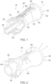
- the rotor 10 has a generally cylindrical shape.
- Rotor 10 has two surface recesses 20, which extend along the longitudinal extent of the rotor 10, generally parallel to the longitudinal axis of rotation 15 of the rotor.
- the surface recesses 20 are provided by concave sections of the rotor.
- the rotor comprises a housing engaging surface area 25 at each end of the rotor and between adjacent surface recesses 20.
- the rotor is hollow and comprises a first rotor cavity 30 and a second rotor cavity 35 arranged consecutively within the rotor 10.
- the rotor comprises a drive shaft 40 that extends within and is attached to the hollow interior of the rotor 10.
- Each end 45, 50 of the rotor 10 is open to provide fluid access into the first and second fluid cavities 30, 35, respectively.
- the rotor 10 further comprises a first groove 52 and a second groove 53 extending along opposing longitudinal edges of the surface recess 20.
- Slots 55, 60 provide the opening between the first rotor cavity 30 and the surface recess 20 and the second rotor cavity 35 and the surface recess 20, respectively.
- Each slot 55, 60 is essentially linear and extends along a longitudinal edge of the recess 20 and is essentially parallel to the longitudinal axis of rotation of the rotor 15.
- slot 55 providing the first opening is located in the first groove 52 and the slot 60 providing the second opening is located in the second groove 53, the slots 55 and 60 are parallel but adjacent opposite sides of the land 25 extending between the recesses 20.
- each of the two surface recesses 20 in the embodiment shown in figure 1 there is a slot 55 providing a first opening between the first rotor cavity 30 and the surface recess 20, and a slot 60 providing a second opening between the second rotor cavity 35 and the surface recess 20.
- the slots 55 and 60 are on opposite sides and opposite ends of the recess 20.
- the view shown in figure 1 shows only 30 one slot 55, 60 of each recess 20.
- both of the slots 55 providing an opening between the first rotor cavity 30 and the surface recesses 20, to allow fluid to flow from the first rotor cavity 35 into the chamber formed by each surface recess 20.
- both of slots 60 will allow fluid to flow from the chamber formed by each surface recess 20 into the second rotor cavity 35.
- Figure 2 illustrates an alternative embodiment of the rotor of figure 1 , without the grooves 52, 53 to locate the slots 55 and 60, but like features are referred to by like reference numerals.
- Figure 2 also illustrates, for a given direction of rotation of the rotor, the direction of fluid flow into the first rotor cavity 30 through the openings in the end 45 of the rotor 10 and from the first rotor cavity out through the slot 55 into the chamber (not shown) formed by the surface recess 20.
- Figure 2 also shows fluid from the adjacent chamber (not shown) formed by the adjacent surface recess 20 flowing into the slot 60 into the second rotor cavity 35 and out through the open end 50 of the rotor 10. This fluid flow will apply equally to the embodiment of figure 1 and figure 2 .
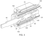
- Figure 3 shows a rotor 105 similar to the rotor 10 of figures 1 and 2 in a housing 100.
- the cross-sectional view of figure 3 shows the arrangement of the first rotor cavity 30 and the second rotor cavity 35 more clearly. It also shows the bulkhead 70 which separates the first and second rotor cavities 30, 35.
- Figure 3 also illustrates more clearly how the drive shaft 40, which is attached to or unitary with the rotor, extends from the interior of hollow the rotor 10. Only one slot 60 is shown in this view, which is the opening between the second rotor cavity 35 and the surface recess (not shown).
- This view illustrates the housing engaging surface area 25 at each end of the rotor and between adjacent surface recesses. (not shown).
- Figure 3 further illustrates parts of two diaphragm chambers 150 each surrounding the rear surface of a diaphragm 120.
- the diaphragm being urged into contact with the rotor 10 by pressurising means (not shown).
- Figures 4 and 5 show a pump 200 having a housing 205, a first fluid port 210 providing a fluid inlet and a second fluid port 215 providing a fluid outlet.
- the housing having an interior surface 220 defining a cavity in which the rotor 225 is located.
- the rotor 225 has a longitudinal axis of rotation indicated by dashed line 230.
- the rotor 225 having surfaces 235 at each end thereof and the lands extending between recesses on the surface thereof together providing a housing engaging surface area of the rotor.
- the rotor shown in figures 4 and 5 is twisted about the longitudinal axis of rotation 230, such that the first end 240 and the second end 245 are offset relative to one another.
- the rotor 225 has two surface recesses 250 provided by concave areas of the rotor surface.
- a resiliently deformable diaphragm 255 is formed by a thinner section of the housing providing the cavity in which the rotor 225 is located.
- the resiliently deformable diaphragm 255 has a rotor engaging surface 257 and a rear surface 260. Pressurising means in the form of a spring 265 is in contact with the rear surface 260 of the diaphragm 255. It can be seen from figures 4 and 5 that the rotor 225 comprises an elongate body that is substantially hollow, comprising a first rotor cavity 270 and a second rotor cavity (not shown).
- the first opening 290 has a tapered shape and extends along a longitudinal edge of a section of the surface recess 250 overlying the first rotor cavity 270 and continues across the land 235 at the first end 240 of the rotor, making an opening in the housing engaging surface provided by the land 235 at the first end 240 of the rotor.
- the rotor also comprises a similarly arranged second opening (not shown) extending between the second rotor cavity (not shown) and the surface recess 250. The second opening will by locating on the opposite longitudinal edge of the recess 250 and at the opposite end of the rotor 225, such that it overlies the second rotor cavity (not shown).
- Each of the two surface recesses 250 has a first opening 290 and a second opening at opposite ends of the rotor and extending along opposite longitudinal edges of each recess 250.
- the rotor 225 is rotated by the action of a motor connected to the drive shaft 285, fluid flows into the first fluid port 210 and then into the first rotor cavity 270 through the open first end 245 of the rotor 225.
- the fluid flows from the first rotor cavity 270 through each first opening 290 into the fluid-conveying cavity provided between the surface recesses 250 and the interior surface 220 of the housing.
- the resiliently deformable diaphragm 255 is urged into contact with the surface of the rotor as it rotates by the action of the spring 265.
- the action of the diaphragm 255 on the surface of the rotor 225 displaces the fluid from the fluid-conveying cavity as the rotor rotates and the fluid flows through the second openings into the second rotor cavity (not shown). From there, the fluid flows out of the pump though the second fluid port 215.
- Figure 6 shows an alternative rotor 300.
- the rotor is twisted about the longitudinal axis of rotation 315 of the rotor 300, such that opposing ends 310,320 of the rotor are off-set relative to one another.
- the result of twisting the rotor is to distort the shape oft he surface recesses 330, 335. Since the first slot 340 providing the opening between the first rotor cavity 350 and the surface recess 330 and the second slot 345 providing the opening between the second rotor cavity 355 and the surface recess 335 extend along opposing edges of the recesses 330, 335, the twisting of the rotor also causes the slots 340, 345 to become angled relative to the longitudinal axis of rotation 315 of the rotor 300.
- Figure 4 also illustrates that twisting the rotor also angles the land 360 between adjacent recesses 330, 335, which becomes angled relative to the longitudinal axis of rotation 315 of the rotor 300.
- Figure 7 shows a rotor 400 which is a variation of the rotor 300 of figure 5 .
- the first slot 440 providing the opening between the first rotor cavity 450 and the surface recess 430 and continues through the first end 410 of the rotor.
- the second slot 445 providing the opening between the second rotor cavity 455 and the surface recess 435, continues through the second end 420 of the rotor. It can be seen that the first slot 440 and the second slot 445 extend through housing engaging surface area 460 at each end of the rotor.
- the dashed lines 465 illustrate the location of the bulkhead extending across the interior of the rotor 400, separating the first rotor cavity 450 and the second rotor cavity 455.
- first and second slots are not limited to a twisted rotor as illustrated in figures 4 and 7 .
- the slots 55, 60 could also extend through the first and second ends 45 50, respectively and through the surface engaging surface area 25.
- Figure 8 shows a rotor 500 which is a variation of the rotor 400 of figure 6 .
- the first slot 540 providing the opening between the first rotor cavity 550 and the surface recess 530.
- the slot is open at the first end 510 of the rotor.
- the second slot 545 providing the opening between the second rotor cavity 555 and the surface recess 535.
- the dashed lines 565 illustrate the location of the bulkhead extending across the interior of the rotor 500, separating the first rotor cavity 550 and the second rotor cavity 555.
- Figure 9 shows part of a pump 600 having a housing 605, a first fluid port 610 providing a fluid inlet and a second fluid port (not shown) providing a fluid outlet.
- the housing having an interior surface 620 defining a cavity in which the rotor 625 is located.
- the rotor 625 has a longitudinal axis of rotation indicated by dashed line 630.
- the rotor 625 having lands 635 at each end thereof and between recesses on the surface thereof together providing a housing engaging surface area of the rotor.
- the rotor 625 has two surface recesses 650 provided by concave areas of the rotor surface.
- the rotor 625 is rotated by the action of a motor connected to the drive shaft 685, fluid flows into the first fluid port 610 and then into the first rotor cavity 670 through the open first end 675 of the rotor 625.
- the fluid flows from the first rotor cavity 670 through each first opening 690 into the fluid-conveying cavity provided between the surface recesses 650 and the interior surface 620 of the housing.
- the resiliently deformable diaphragm 655 is urged into contact with the surface of the rotor as it rotates by the action of pressurising means (not shown).
- the action of the diaphragm 655 on the surface of the rotor 625 displaces the fluid from the fluid-conveying cavity as the rotor rotates and the fluid flows through the second openings (not shown) into the second rotor cavity (not shown). From there, the fluid flows out of the pump though the second fluid port (not shown).
- Figure 10 shows part of a pump 700 having a housing 705, a first fluid port 710 providing a fluid inlet and a second fluid port (not shown) providing a fluid outlet.
- the housing having an interior surface 720 defining a cavity in which the rotor 725 is located.
- the rotor 725 has a longitudinal axis of rotation indicated by dashed line 730.
- the rotor 725 having lands 735 at each end thereof and between recesses on the surface thereof together providing a housing engaging surface area of the rotor.
- the rotor 725 has two surface recesses 750 provided by concave areas of the rotor surface.
- a resiliently deformable diaphragm 755 is formed by a thinner section of the housing providing the cavity in which the rotor 725 is located.
- the resiliently deformable diaphragm 755 has a rotor engaging surface 757 and a rear surface 760.
- the resiliently deformable diaphragm 755 has a linear rib 765 protruding from the rear surface 760 of the diaphragm 755.
- the linear rib 765 is angled relative to the longitudinal axis of rotation 730 of the rotor.
- the rotor 725 comprises an elongate body that is substantially hollow, comprising a first rotor cavity 770 and a second rotor cavity (not shown) at the opposite end of the rotor 725.
- the rotor 725 is twisted about the longitudinal axis of rotation 730, such that opposite ends of the rotor 725 are offset relative to one another.
- the rotor 725 is twisted in the opposite direction to the direction that the rib 765 is angled relative to the longitudinal axis of rotation 730 of the rotor.
- the first rotor cavity 770 has openings at a first end 775 of the rotor and the second rotor cavity (not shown) has openings (not shown) at a second end of the rotor (not shown).
- the first rotor cavity 770 and the second rotor cavity (not shown) are separated from each other by a bulkhead (not shown) that extends across the full interior of the hollow rotor, to prevent fluid flowing along the full internal length of the rotor.
- the rotor 725 comprises a first opening 790 extending between the first rotor cavity 770 and the surface recess 750 of the rotor.
- the first opening 790 has a has a tapered shape and extends along a longitudinal edge of a section of the surface recess 750 overlying the first rotor cavity 770 and continues across the land 735 at the first end 775 of the rotor, making an opening in the housing engaging surface provided by the land 735 at the first end 775 of the rotor.
- the rotor also comprises a similarly arranged second opening (not shown) extending between the second rotor cavity (not shown) and the surface recess 750.
- the second opening is located on the opposite longitudinal edge of the recess 750 and at the opposite end of the rotor 725, such that it overlies the second rotor cavity (not shown).
- Each surface recess 750 has a first opening and a second opening arranged at opposite ends of the rotor and on opposite sides of the recess.
- the rotor 725 is rotated by the action of a motor connected to the drive shaft 785, fluid flows into the first fluid port 710 and then into the first rotor cavity 770 through the open first end 775 of the rotor 725.
- the fluid flows from the first rotor cavity 770 through each first opening 790 into the fluid-conveying cavity provided between the surface recesses 750 and the interior surface 720 of the housing.
- the resiliently deformable diaphragm 755 is urged into contact with the surface of the rotor as it rotates by the action of pressurising means (not shown).
- the action of the diaphragm 755 on the surface of the rotor 725 displaces the fluid from the fluid-conveying cavity as the rotor rotates and the fluid flows through the second openings into the second rotor cavity (not shown). From there, the fluid flows out of the pump though the second fluid port (not shown).
- Figure 11 illustrates a cross-sectional view though part of a pump according to an embodiment of this invention.
- This figure illustrates the action of a plurality of diaphragm on the surface of a rotor comprising a plurality of recesses.
- figure 11 shows a housing 910 comprising three resiliently deformable diaphragm 920 each formed as a unit with the housing as provided by a thinner section of the housing.
- the section of housing providing the diaphragms being sufficiently thin to make the diaphragms resiliently deformable.
- the three diaphragms 920 are equidistantly spaced about the circumference of the rotor 930.
- Each recess comprises a first opening 1035 between the first rotor cavity 1010 and the recess 1025, 1030 and a second opening 1040 between the recesses 1025 and 1030 and the second rotor cavity 1015.
- first openings 1035 and the second openings 1040 in the rotor 1000 extend along a major portion of opposing longitudinal edges of each recess 1025, 1030.
- the arrangement of the first and second openings 1035, 1040 and the bulkhead 1020 are such that the first openings 1035 only open into first rotor cavity 1010 and the second openings 1040 only open into the second rotor cavity 1015.
- the first rotor cavity is open at only a first end 1045 of the rotor and the second rotor cavity 1015 is open only at a second end 1050 of the rotor.
Landscapes
- Engineering & Computer Science (AREA)
- Mechanical Engineering (AREA)
- General Engineering & Computer Science (AREA)
- Reciprocating Pumps (AREA)
- Details And Applications Of Rotary Liquid Pumps (AREA)
- Fluid-Driven Valves (AREA)
Priority Applications (1)
| Application Number | Priority Date | Filing Date | Title |
|---|---|---|---|
| EP25169304.0A EP4592530A1 (en) | 2021-05-12 | 2022-05-12 | Pumps |
Applications Claiming Priority (2)
| Application Number | Priority Date | Filing Date | Title |
|---|---|---|---|
| GB2106742.6A GB2606544B (en) | 2021-05-12 | 2021-05-12 | Pumps |
| PCT/EP2022/062978 WO2022238548A1 (en) | 2021-05-12 | 2022-05-12 | Pumps |
Related Child Applications (1)
| Application Number | Title | Priority Date | Filing Date |
|---|---|---|---|
| EP25169304.0A Division EP4592530A1 (en) | 2021-05-12 | 2022-05-12 | Pumps |
Publications (2)
| Publication Number | Publication Date |
|---|---|
| EP4337864A1 EP4337864A1 (en) | 2024-03-20 |
| EP4337864B1 true EP4337864B1 (en) | 2025-04-09 |
Family
ID=81984729
Family Applications (2)
| Application Number | Title | Priority Date | Filing Date |
|---|---|---|---|
| EP22728885.9A Active EP4337864B1 (en) | 2021-05-12 | 2022-05-12 | Pumps |
| EP25169304.0A Pending EP4592530A1 (en) | 2021-05-12 | 2022-05-12 | Pumps |
Family Applications After (1)
| Application Number | Title | Priority Date | Filing Date |
|---|---|---|---|
| EP25169304.0A Pending EP4592530A1 (en) | 2021-05-12 | 2022-05-12 | Pumps |
Country Status (9)
| Country | Link |
|---|---|
| US (2) | US12203474B2 (https=) |
| EP (2) | EP4337864B1 (https=) |
| JP (1) | JP2024518977A (https=) |
| CN (1) | CN118103597A (https=) |
| AU (1) | AU2022275010A1 (https=) |
| GB (1) | GB2606544B (https=) |
| IL (1) | IL308479A (https=) |
| MX (1) | MX2023013391A (https=) |
| WO (1) | WO2022238548A1 (https=) |
Families Citing this family (2)
| Publication number | Priority date | Publication date | Assignee | Title |
|---|---|---|---|---|
| GB2606542B (en) * | 2021-05-12 | 2023-10-11 | Psg Germany Gmbh | Pumps |
| GB2606544B (en) * | 2021-05-12 | 2023-07-12 | Psg Germany Gmbh | Pumps |
Family Cites Families (15)
| Publication number | Priority date | Publication date | Assignee | Title |
|---|---|---|---|---|
| WO2000073627A1 (en) * | 1999-05-31 | 2000-12-07 | Merlin Corporation Pty Ltd | Fluid rotary machine |
| GB0419848D0 (en) * | 2004-09-07 | 2004-10-13 | Carbonate Ltd | Pumps |
| GB0906768D0 (en) * | 2009-04-21 | 2009-06-03 | Pdd Innovations Ltd | Pumps |
| JP2013521990A (ja) * | 2010-03-23 | 2013-06-13 | バクスター・インターナショナル・インコーポレイテッド | 回転式注入ポンプ |
| GB201117297D0 (en) * | 2011-10-07 | 2011-11-16 | Quantex Patents Ltd | Pump fittings and methods for their manufacture |
| GB201117300D0 (en) * | 2011-10-07 | 2011-11-16 | Quantex Patents Ltd | Pumps |
| GB201202255D0 (en) | 2012-02-09 | 2012-03-28 | Quantex Patents Ltd | Pumps |
| GB2507029B (en) * | 2012-07-11 | 2019-04-17 | Quantex Patents Ltd | Pump fittings and methods for their manufacture |
| GB201218428D0 (en) * | 2012-10-15 | 2012-11-28 | Quantex Patents Ltd | Pump assemblies |
| AU2013202729A1 (en) * | 2012-12-12 | 2014-06-26 | Greystone Technologies Pty Ltd | A Rotary Fluid Machine and Associated Method of Operation |
| GB201303903D0 (en) | 2013-03-05 | 2013-04-17 | Quantex Patents Ltd | Pumps |
| WO2015001571A2 (en) * | 2013-07-04 | 2015-01-08 | Paul Maria | Positive displacement pump mechanism used for pumps and water turbines |
| GB201504553D0 (en) * | 2015-03-18 | 2015-05-06 | Quantex Patents Ltd | Pumps |
| GB2547051A (en) * | 2016-02-08 | 2017-08-09 | Quantex Patents Ltd | Pump assembly |
| GB2606544B (en) * | 2021-05-12 | 2023-07-12 | Psg Germany Gmbh | Pumps |
-
2021
- 2021-05-12 GB GB2106742.6A patent/GB2606544B/en active Active
-
2022
- 2022-05-12 AU AU2022275010A patent/AU2022275010A1/en not_active Abandoned
- 2022-05-12 JP JP2023570007A patent/JP2024518977A/ja active Pending
- 2022-05-12 IL IL308479A patent/IL308479A/en unknown
- 2022-05-12 WO PCT/EP2022/062978 patent/WO2022238548A1/en not_active Ceased
- 2022-05-12 EP EP22728885.9A patent/EP4337864B1/en active Active
- 2022-05-12 EP EP25169304.0A patent/EP4592530A1/en active Pending
- 2022-05-12 US US18/560,359 patent/US12203474B2/en active Active
- 2022-05-12 CN CN202280049485.6A patent/CN118103597A/zh active Pending
- 2022-05-12 MX MX2023013391A patent/MX2023013391A/es unknown
-
2025
- 2025-01-17 US US19/027,610 patent/US20250154953A1/en active Pending
Also Published As
| Publication number | Publication date |
|---|---|
| EP4337864A1 (en) | 2024-03-20 |
| WO2022238548A1 (en) | 2022-11-17 |
| AU2022275010A1 (en) | 2023-11-30 |
| US12203474B2 (en) | 2025-01-21 |
| MX2023013391A (es) | 2024-04-09 |
| IL308479A (en) | 2024-01-01 |
| EP4592530A1 (en) | 2025-07-30 |
| GB2606544B (en) | 2023-07-12 |
| GB2606544A (en) | 2022-11-16 |
| CN118103597A (zh) | 2024-05-28 |
| US20240280100A1 (en) | 2024-08-22 |
| JP2024518977A (ja) | 2024-05-08 |
| US20250154953A1 (en) | 2025-05-15 |
Similar Documents
| Publication | Publication Date | Title |
|---|---|---|
| US20250154953A1 (en) | Pumps | |
| EP1787027B1 (en) | Rotary pump with resiliently deformed seal | |
| ES2968248T3 (es) | Ensamble de bomba | |
| CN103958832A (zh) | 泵 | |
| US3507585A (en) | Rotary diaphragm pump | |
| US20250347277A1 (en) | Pumps | |
| US20180073503A1 (en) | Pumps | |
| WO2006032415A1 (en) | Rotary displacement pump comprising scraper and guide of the scraper | |
| EP3650694B1 (en) | Liquid pumping device | |
| EP3752736B1 (en) | Pump apparatus | |
| HK40002063B (en) | Pump assembly | |
| HK40002063A (en) | Pump assembly |
Legal Events
| Date | Code | Title | Description |
|---|---|---|---|
| STAA | Information on the status of an ep patent application or granted ep patent |
Free format text: STATUS: UNKNOWN |
|
| STAA | Information on the status of an ep patent application or granted ep patent |
Free format text: STATUS: THE INTERNATIONAL PUBLICATION HAS BEEN MADE |
|
| PUAI | Public reference made under article 153(3) epc to a published international application that has entered the european phase |
Free format text: ORIGINAL CODE: 0009012 |
|
| STAA | Information on the status of an ep patent application or granted ep patent |
Free format text: STATUS: REQUEST FOR EXAMINATION WAS MADE |
|
| 17P | Request for examination filed |
Effective date: 20231120 |
|
| AK | Designated contracting states |
Kind code of ref document: A1 Designated state(s): AL AT BE BG CH CY CZ DE DK EE ES FI FR GB GR HR HU IE IS IT LI LT LU LV MC MK MT NL NO PL PT RO RS SE SI SK SM TR |
|
| GRAP | Despatch of communication of intention to grant a patent |
Free format text: ORIGINAL CODE: EPIDOSNIGR1 |
|
| STAA | Information on the status of an ep patent application or granted ep patent |
Free format text: STATUS: GRANT OF PATENT IS INTENDED |
|
| RIC1 | Information provided on ipc code assigned before grant |
Ipc: F01C 21/08 20060101ALI20240304BHEP Ipc: F04C 5/00 20060101AFI20240304BHEP |
|
| DAV | Request for validation of the european patent (deleted) | ||
| DAX | Request for extension of the european patent (deleted) | ||
| INTG | Intention to grant announced |
Effective date: 20240326 |
|
| GRAJ | Information related to disapproval of communication of intention to grant by the applicant or resumption of examination proceedings by the epo deleted |
Free format text: ORIGINAL CODE: EPIDOSDIGR1 |
|
| STAA | Information on the status of an ep patent application or granted ep patent |
Free format text: STATUS: REQUEST FOR EXAMINATION WAS MADE |
|
| INTC | Intention to grant announced (deleted) | ||
| GRAP | Despatch of communication of intention to grant a patent |
Free format text: ORIGINAL CODE: EPIDOSNIGR1 |
|
| STAA | Information on the status of an ep patent application or granted ep patent |
Free format text: STATUS: GRANT OF PATENT IS INTENDED |
|
| INTG | Intention to grant announced |
Effective date: 20241030 |
|
| GRAS | Grant fee paid |
Free format text: ORIGINAL CODE: EPIDOSNIGR3 |
|
| GRAA | (expected) grant |
Free format text: ORIGINAL CODE: 0009210 |
|
| STAA | Information on the status of an ep patent application or granted ep patent |
Free format text: STATUS: THE PATENT HAS BEEN GRANTED |
|
| AK | Designated contracting states |
Kind code of ref document: B1 Designated state(s): AL AT BE BG CH CY CZ DE DK EE ES FI FR GB GR HR HU IE IS IT LI LT LU LV MC MK MT NL NO PL PT RO RS SE SI SK SM TR |
|
| REG | Reference to a national code |
Ref country code: GB Ref legal event code: FG4D |
|
| REG | Reference to a national code |
Ref country code: CH Ref legal event code: EP |
|
| REG | Reference to a national code |
Ref country code: DE Ref legal event code: R096 Ref document number: 602022012975 Country of ref document: DE |
|
| REG | Reference to a national code |
Ref country code: IE Ref legal event code: FG4D |
|
| P01 | Opt-out of the competence of the unified patent court (upc) registered |
Free format text: CASE NUMBER: APP_18611/2025 Effective date: 20250416 |
|
| PGFP | Annual fee paid to national office [announced via postgrant information from national office to epo] |
Ref country code: AT Payment date: 20250721 Year of fee payment: 4 |
|
| REG | Reference to a national code |
Ref country code: NL Ref legal event code: MP Effective date: 20250409 |
|
| PG25 | Lapsed in a contracting state [announced via postgrant information from national office to epo] |
Ref country code: NL Free format text: LAPSE BECAUSE OF FAILURE TO SUBMIT A TRANSLATION OF THE DESCRIPTION OR TO PAY THE FEE WITHIN THE PRESCRIBED TIME-LIMIT Effective date: 20250409 |
|
| REG | Reference to a national code |
Ref country code: AT Ref legal event code: MK05 Ref document number: 1783720 Country of ref document: AT Kind code of ref document: T Effective date: 20250409 |
|
| PG25 | Lapsed in a contracting state [announced via postgrant information from national office to epo] |
Ref country code: FI Free format text: LAPSE BECAUSE OF FAILURE TO SUBMIT A TRANSLATION OF THE DESCRIPTION OR TO PAY THE FEE WITHIN THE PRESCRIBED TIME-LIMIT Effective date: 20250409 Ref country code: PT Free format text: LAPSE BECAUSE OF FAILURE TO SUBMIT A TRANSLATION OF THE DESCRIPTION OR TO PAY THE FEE WITHIN THE PRESCRIBED TIME-LIMIT Effective date: 20250811 Ref country code: ES Free format text: LAPSE BECAUSE OF FAILURE TO SUBMIT A TRANSLATION OF THE DESCRIPTION OR TO PAY THE FEE WITHIN THE PRESCRIBED TIME-LIMIT Effective date: 20250409 |
|
| PGFP | Annual fee paid to national office [announced via postgrant information from national office to epo] |
Ref country code: DE Payment date: 20250724 Year of fee payment: 4 |
|
| REG | Reference to a national code |
Ref country code: LT Ref legal event code: MG9D |
|
| PG25 | Lapsed in a contracting state [announced via postgrant information from national office to epo] |
Ref country code: GR Free format text: LAPSE BECAUSE OF FAILURE TO SUBMIT A TRANSLATION OF THE DESCRIPTION OR TO PAY THE FEE WITHIN THE PRESCRIBED TIME-LIMIT Effective date: 20250710 Ref country code: NO Free format text: LAPSE BECAUSE OF FAILURE TO SUBMIT A TRANSLATION OF THE DESCRIPTION OR TO PAY THE FEE WITHIN THE PRESCRIBED TIME-LIMIT Effective date: 20250709 |
|
| PG25 | Lapsed in a contracting state [announced via postgrant information from national office to epo] |
Ref country code: PL Free format text: LAPSE BECAUSE OF FAILURE TO SUBMIT A TRANSLATION OF THE DESCRIPTION OR TO PAY THE FEE WITHIN THE PRESCRIBED TIME-LIMIT Effective date: 20250409 |
|
| PG25 | Lapsed in a contracting state [announced via postgrant information from national office to epo] |
Ref country code: BG Free format text: LAPSE BECAUSE OF FAILURE TO SUBMIT A TRANSLATION OF THE DESCRIPTION OR TO PAY THE FEE WITHIN THE PRESCRIBED TIME-LIMIT Effective date: 20250409 |
|
| PG25 | Lapsed in a contracting state [announced via postgrant information from national office to epo] |
Ref country code: HR Free format text: LAPSE BECAUSE OF FAILURE TO SUBMIT A TRANSLATION OF THE DESCRIPTION OR TO PAY THE FEE WITHIN THE PRESCRIBED TIME-LIMIT Effective date: 20250409 Ref country code: AT Free format text: LAPSE BECAUSE OF FAILURE TO SUBMIT A TRANSLATION OF THE DESCRIPTION OR TO PAY THE FEE WITHIN THE PRESCRIBED TIME-LIMIT Effective date: 20250409 |
|
| PGFP | Annual fee paid to national office [announced via postgrant information from national office to epo] |
Ref country code: FR Payment date: 20250722 Year of fee payment: 4 |
|
| PG25 | Lapsed in a contracting state [announced via postgrant information from national office to epo] |
Ref country code: RS Free format text: LAPSE BECAUSE OF FAILURE TO SUBMIT A TRANSLATION OF THE DESCRIPTION OR TO PAY THE FEE WITHIN THE PRESCRIBED TIME-LIMIT Effective date: 20250709 |
|
| PGFP | Annual fee paid to national office [announced via postgrant information from national office to epo] |
Ref country code: IE Payment date: 20250723 Year of fee payment: 4 |
|
| PG25 | Lapsed in a contracting state [announced via postgrant information from national office to epo] |
Ref country code: IS Free format text: LAPSE BECAUSE OF FAILURE TO SUBMIT A TRANSLATION OF THE DESCRIPTION OR TO PAY THE FEE WITHIN THE PRESCRIBED TIME-LIMIT Effective date: 20250809 |
|
| PG25 | Lapsed in a contracting state [announced via postgrant information from national office to epo] |
Ref country code: LV Free format text: LAPSE BECAUSE OF FAILURE TO SUBMIT A TRANSLATION OF THE DESCRIPTION OR TO PAY THE FEE WITHIN THE PRESCRIBED TIME-LIMIT Effective date: 20250409 |
|
| REG | Reference to a national code |
Ref country code: CH Ref legal event code: H13 Free format text: ST27 STATUS EVENT CODE: U-0-0-H10-H13 (AS PROVIDED BY THE NATIONAL OFFICE) Effective date: 20251223 |
|
| REG | Reference to a national code |
Ref country code: DE Ref legal event code: R097 Ref document number: 602022012975 Country of ref document: DE |
|
| PG25 | Lapsed in a contracting state [announced via postgrant information from national office to epo] |
Ref country code: DK Free format text: LAPSE BECAUSE OF FAILURE TO SUBMIT A TRANSLATION OF THE DESCRIPTION OR TO PAY THE FEE WITHIN THE PRESCRIBED TIME-LIMIT Effective date: 20250409 Ref country code: SM Free format text: LAPSE BECAUSE OF FAILURE TO SUBMIT A TRANSLATION OF THE DESCRIPTION OR TO PAY THE FEE WITHIN THE PRESCRIBED TIME-LIMIT Effective date: 20250409 |
|
| PG25 | Lapsed in a contracting state [announced via postgrant information from national office to epo] |
Ref country code: LU Free format text: LAPSE BECAUSE OF NON-PAYMENT OF DUE FEES Effective date: 20250512 |
|
| PG25 | Lapsed in a contracting state [announced via postgrant information from national office to epo] |
Ref country code: CH Free format text: LAPSE BECAUSE OF NON-PAYMENT OF DUE FEES Effective date: 20250531 |
|
| PG25 | Lapsed in a contracting state [announced via postgrant information from national office to epo] |
Ref country code: CZ Free format text: LAPSE BECAUSE OF FAILURE TO SUBMIT A TRANSLATION OF THE DESCRIPTION OR TO PAY THE FEE WITHIN THE PRESCRIBED TIME-LIMIT Effective date: 20250409 |
|
| PG25 | Lapsed in a contracting state [announced via postgrant information from national office to epo] |
Ref country code: EE Free format text: LAPSE BECAUSE OF FAILURE TO SUBMIT A TRANSLATION OF THE DESCRIPTION OR TO PAY THE FEE WITHIN THE PRESCRIBED TIME-LIMIT Effective date: 20250409 |
|
| PG25 | Lapsed in a contracting state [announced via postgrant information from national office to epo] |
Ref country code: SK Free format text: LAPSE BECAUSE OF FAILURE TO SUBMIT A TRANSLATION OF THE DESCRIPTION OR TO PAY THE FEE WITHIN THE PRESCRIBED TIME-LIMIT Effective date: 20250409 |
|
| PG25 | Lapsed in a contracting state [announced via postgrant information from national office to epo] |
Ref country code: IT Free format text: LAPSE BECAUSE OF FAILURE TO SUBMIT A TRANSLATION OF THE DESCRIPTION OR TO PAY THE FEE WITHIN THE PRESCRIBED TIME-LIMIT Effective date: 20250409 |
|
| REG | Reference to a national code |
Ref country code: BE Ref legal event code: MM Effective date: 20250531 |
|
| PG25 | Lapsed in a contracting state [announced via postgrant information from national office to epo] |
Ref country code: MC Free format text: LAPSE BECAUSE OF FAILURE TO SUBMIT A TRANSLATION OF THE DESCRIPTION OR TO PAY THE FEE WITHIN THE PRESCRIBED TIME-LIMIT Effective date: 20250409 |
|
| PLBE | No opposition filed within time limit |
Free format text: ORIGINAL CODE: 0009261 |
|
| STAA | Information on the status of an ep patent application or granted ep patent |
Free format text: STATUS: NO OPPOSITION FILED WITHIN TIME LIMIT |
|
| REG | Reference to a national code |
Ref country code: CH Ref legal event code: L10 Free format text: ST27 STATUS EVENT CODE: U-0-0-L10-L00 (AS PROVIDED BY THE NATIONAL OFFICE) Effective date: 20260218 |
|
| PG25 | Lapsed in a contracting state [announced via postgrant information from national office to epo] |
Ref country code: RO Free format text: LAPSE BECAUSE OF FAILURE TO SUBMIT A TRANSLATION OF THE DESCRIPTION OR TO PAY THE FEE WITHIN THE PRESCRIBED TIME-LIMIT Effective date: 20250409 |
|
| 26N | No opposition filed |
Effective date: 20260112 |
|
| PG25 | Lapsed in a contracting state [announced via postgrant information from national office to epo] |
Ref country code: BE Free format text: LAPSE BECAUSE OF NON-PAYMENT OF DUE FEES Effective date: 20250531 |