EP4337533B1 - Sitzeinheit mit einer geräuschdämpfungsplatte - Google Patents
Sitzeinheit mit einer geräuschdämpfungsplatte Download PDFInfo
- Publication number
- EP4337533B1 EP4337533B1 EP22728139.1A EP22728139A EP4337533B1 EP 4337533 B1 EP4337533 B1 EP 4337533B1 EP 22728139 A EP22728139 A EP 22728139A EP 4337533 B1 EP4337533 B1 EP 4337533B1
- Authority
- EP
- European Patent Office
- Prior art keywords
- seat
- support plate
- sound
- seat unit
- face
- Prior art date
- Legal status (The legal status is an assumption and is not a legal conclusion. Google has not performed a legal analysis and makes no representation as to the accuracy of the status listed.)
- Active
Links
Images


Classifications
-
- B—PERFORMING OPERATIONS; TRANSPORTING
- B64—AIRCRAFT; AVIATION; COSMONAUTICS
- B64D—EQUIPMENT FOR FITTING IN OR TO AIRCRAFT; FLIGHT SUITS; PARACHUTES; ARRANGEMENT OR MOUNTING OF POWER PLANTS OR PROPULSION TRANSMISSIONS IN AIRCRAFT
- B64D11/00—Passenger or crew accommodation; Flight-deck installations not otherwise provided for
- B64D11/06—Arrangements of seats, or adaptations or details specially adapted for aircraft seats
- B64D11/0606—Arrangements of seats, or adaptations or details specially adapted for aircraft seats with privacy shells, screens, separators or the like
-
- B—PERFORMING OPERATIONS; TRANSPORTING
- B60—VEHICLES IN GENERAL
- B60N—SEATS SPECIALLY ADAPTED FOR VEHICLES; VEHICLE PASSENGER ACCOMMODATION NOT OTHERWISE PROVIDED FOR
- B60N2/00—Seats specially adapted for vehicles; Arrangement or mounting of seats in vehicles
- B60N2/90—Details or parts not otherwise provided for
- B60N2/91—Panels between front seats
-
- B—PERFORMING OPERATIONS; TRANSPORTING
- B64—AIRCRAFT; AVIATION; COSMONAUTICS
- B64D—EQUIPMENT FOR FITTING IN OR TO AIRCRAFT; FLIGHT SUITS; PARACHUTES; ARRANGEMENT OR MOUNTING OF POWER PLANTS OR PROPULSION TRANSMISSIONS IN AIRCRAFT
- B64D11/00—Passenger or crew accommodation; Flight-deck installations not otherwise provided for
- B64D11/06—Arrangements of seats, or adaptations or details specially adapted for aircraft seats
Definitions
- the present invention relates to a seat unit provided with a noise attenuating panel.
- the invention finds a particularly advantageous, but not exclusive, application with the "business class” and "first class” type seat units of an aircraft cabin.
- such a seat unit comprises a seat associated with a side console provided with storage and a shell extending at least partly around the seat so as to delimit a semi-enclosed space around the passenger.
- the seat offers the passenger different comfort positions, from a "sitting" position to a “lying” position, in which the seat defines a substantially horizontal sleeping surface for the passenger to lie down.
- Intermediate comfort positions are also offered, such as the "relax" position in which a seat back is strongly inclined. Generally, these intermediate positions are obtained by tilting the pivoting back about a horizontal axis and perpendicular to an extension axis of the seat. The passenger can then remain on the seat during transitions between the different positions.
- the seat generally consists in particular of the back and a seat and is likely to include a leg rest and/or a foot rest, which may be fixed or linked to a kinematics of the seat.
- Noise that may disturb passengers' rest is an important environmental concern to consider when developing a seating unit. There is therefore a need to reduce the perception of noise inside an aircraft cabin in order to optimize the acoustic comfort of passengers without reducing their living space.
- the document WO2019/239204 describes a privacy screen for a passenger seat comprising a frame defining a privacy screen perimeter disposed around the seat and a sound-absorbing layer positioned within the frame and surrounded by a textile shell to provide physical, visual and acoustic privacy to a passenger.
- the invention thus makes it possible, thanks to the production of through holes in the support plate, to propose a compact sound trap integrated into the environmental element of the seat.
- the through holes allow the passage of sound waves inside the empty space separating the support plate from the environmental element of the seat, so that after multiple reflections inside this space, the noise intensity perceived by the passenger at the seat is greatly reduced.
- the noise attenuating panel further comprises a layer of sound-absorbing material arranged between the covering cap and the support plate.
- the layer of sound-absorbing material is made of a material chosen in particular from: a fibrous material, a non-woven material, a wadding-based material, or a foam-based material.
- the noise attenuating panel is configured so as to have a sound absorption peak for frequencies between 20Hz and 20kHz, preferably between 600Hz and 4KHz.
- a height of the empty space between the support plate and the face of the environmental element is between 1 mm and 15 mm and is preferably 3 mm.
- the support plate is made of a thermoformed plastic material or is constituted by an injected plastic part.
- the support plate comprises at least one through hole having a diameter of between 1 mm and 15 mm. If the support plate has several holes, these holes may all be of the same diameter or of different diameters. Similarly, the shape of these holes is not limited to circular shapes but to all possible geometric shapes.
- the support plate comprises feet resting against the face of the surrounding element of the seat.
- the support plate comprises removable fixing means for fixing the noise attenuating panel to the face of the seat environment element.
- the covering cap is made of a sound-permeable material.
- the environmental element associated with the seat is chosen from: a privacy shell extending at least partly around the seat, a console, or an ottoman.
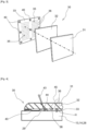
- FIG. 1 shows a seat unit 10 comprising a seat 12 associated with a side console 13 extending along one side of the seat 12.
- a shell 14, called a privacy shell extends at least partly around the seat 12 so as to delimit a semi-enclosed space around the passenger.
- the privacy shell 14 is made for example from a composite material. Such a configuration makes it possible to guarantee the privacy of the passenger seated on the seat 12.
- a video screen 16 of a multimedia system or IFE may be installed on a rear part of the privacy shell 14 so as to be usable by a rear passenger.
- the console 13 may include an upper face 17 forming a table on which the passenger can place objects as well as a storage space 18 comprising one or more elements from a literature pocket, a bottle holder, or a minibar.
- the choice of storage is configurable according to the wishes of the airline.
- the console 13 may also include a reading light 19 intended to direct lighting towards the seat 12.
- a cavity 21 is located under the upper wall.
- the cavity 21 is open laterally towards the seat 12.
- a horizontal face 22 of the console 13 has in particular an armrest function.
- the horizontal face 22 may locally have the shape of a curved cuff 23 matching the shape of a part of the passenger's arm.
- the console 13 also includes a control unit 25 for the seat 12 and its ancillary components (called a "PCU” for "Passenger Control Unit” in English).
- the control unit 25 allows the passenger in particular to control the selection of a position of the seat 12 as well as the ancillary components, such as a video system, a heating device, a lighting ambiance system, or any other ancillary component that can be integrated into the seat 12.
- the seat unit 10 may also conventionally include a meal tray 26 movable between a stored position (corresponding to that shown in the figure 1 ) in which the meal tray 26 is located inside a housing provided in the console 13 and a deployed position in which the meal tray 26 is located outside the housing to allow the passenger to place a meal tray there.
- the seat 12 is advantageously provided with kinematics allowing it to be mobile between a "seated” position, in which the seat 12 is configured to define a seated position of a passenger, and a "reclined” position, in which the seat 12 is configured to define a sleeping surface of the passenger, advantageously substantially horizontal. Positions Intermediate comfort positions are also offered, such as the "relax" position in which the back of the seat 12 is strongly inclined.
- the console 13 has a housing 27 seen through the transparency of the figure 1 in which an ottoman 28 is arranged.
- the ottoman 28 has a horizontal face forming a footrest on which a rear passenger can place his feet when the seat 12 is in the "reclined" position.
- the seat 12 comprises an extension axis X1 defined by the intersection between a horizontal plane and a vertical median plane of the seat 12 corresponding to a plane of symmetry of the seat 12.
- the extension axis X1 of the seat 12 may form a non-zero angle with respect to a direction parallel to or coincident with a central axis of the aircraft. In this case, the seat 12 is turned in the direction of the axis. Alternatively, the seat 12 may be turned in a direction opposite to the axis X2.
- a noise-reducing panel 30 may be fixed to one face of the privacy shell 14.
- the noise-reducing panel 30 may be fixed to a front face of the privacy shell 14 located on the side of the seat 12.
- the noise-reducing panel 30 may be fixed to the rear face of the privacy shell 14.
- the noise-reducing panel 30 may also be fixed to a side face of the console 13 located on the side of the seat 12 or to a face of the ottoman 28.
- the noise-reducing panel 30 may be fixed to one or more environmental elements of the seat, notably chosen from: the privacy shell 14, the console 13, or the ottoman 28.
- noise-attenuating panels 30 are provided on the faces of the various environmental elements 13, 14, 18 surrounding the passenger when the seat 12 is in the reclined position. This makes it possible to create a silent space around the passenger when he sleeps to improve his comfort.
- a noise-attenuating panel 30 may be arranged only on the face of one of the environmental elements of the seat 12.
- this noise attenuating panel 30 comprises a trim cover 31, a layer of sound-absorbing material 32, and a support plate 33.
- the support plate 33 comprises at least one sound-permeable portion 35 provided with at least one through-hole 36.
- the sound-permeable portion 35 is provided with a plurality of through-holes 36 (also called perforations 36).
- the support plate 33 is arranged such that there is an empty space 38 between the sound-permeable portion 35 and the face 29 of the seat surrounding element on which the panel 30 is fixed.
- a sound trap is thus formed in which the through holes 36 allow the passage of sound waves inside the empty space 38 separating the support plate 33 from the face 29 of the environmental element of the seat 12. After multiple reflections between the face 29 of the environmental element and the layer of sound-absorbing material 32, the noise intensity perceived by the passenger at the seat 12 is greatly reduced.
- the covering cap 31 is made of a sound-permeable material.
- the material of the covering cap 31 is also chosen to provide an aesthetic finish to the assembly.
- the covering cap 31 may, for example, be made of a material such as textile, leather, imitation leather, alcantara or any other flexible material suitable for the application.
- the material used may include a multitude of perforations to facilitate the passage of sound through the covering cap 31.
- the trim cover 31 may have decorative patterns on its visible parts when the panel 30 is placed on the seat environment element 12. These decorative patterns may be personalized depending on the airline.
- the layer of sound-absorbing material 32 is arranged between the covering cap 31 and the support plate 33.
- the layer of sound-absorbing material 32 is made of a material chosen in particular from: a fibrous material, a non-woven material, wadding-based material, or foam-based material or any other sound absorbing material suitable for the application.
- the support plate 33 is advantageously made of a thermoformed plastic material.
- the support plate 33 has a small thickness, for example between 1 mm and 3 mm.
- a plate 33 made of a thermoplastic material is used. This plate is heated and then shaped using a die. Once cooled, the plate retains the shape printed by the die.
- the support plate 33 may have a curved shape corresponding to that of the seat environment element 12.
- the thermoforming die may impose on the support plate 33 a curvature corresponding to that of the privacy shell 14. Such a configuration makes it possible to maintain the gap between the support plate 33 and the face 29 of the privacy shell 14 substantially constant.
- a machining step called "trimming” can then be carried out, consisting of cutting an edge of the part not used for finishing. It is possible to take advantage of this machining step to produce the through holes 36 in the support plate 33 in order to obtain the sound-permeable portion 35.
- the plate used for thermoforming may have been perforated prior to the plate heating step. In all cases, the through holes 36 of the support plate 33 do not extend into the layer of sound-absorbing material 32.
- the support plate 33 is made of an injected plastic part.
- the through holes 36 can be obtained directly during the injection of the part.
- the support plate 33 comprises feet 40 bearing against the face 29 of the environmental element 13, 14, 28 so as to create the empty space 38 between the sound-permeable portion 35 and the environmental element.
- the feet 40 may be formed by local shaping of the support plate 33.
- support plate 33 thus comprises projecting portions forming feet 40 integral with the rest of the support plate 33.
- the covering cap 31 covers the layer of sound-absorbing material 32 arranged against the support plate 33, as shown in the figure 2 .
- the covering cap 31 is provided with a flap 41 fixed against an edge of the support plate 33.
- the fixing of the flap 41 of the covering cap 31 on the panel 30 may be carried out by gluing, by insertion into a retaining groove, or any other suitable fixing technique with or without gluing.
- the support plate 33 comprises removable fixing means 42 for fixing the noise attenuating panel 30 on the face 29 of the environmental element 13, 14, 28 of the seat 12.
- the choice of the fixing means 42 depends in particular on the constraints of integration of the panel 30 and its positioning in the seat unit 10.
- discreet fixing means 42 that can be removed without using a tool are preferably used, such as for example snap-on devices, so-called "Velcro” fasteners (registered trademark) formed by complementary loops and hooks, magnetic fasteners, or any other fixing device adapted to the application.
- the Velcro fasteners or the magnetic fasteners have a thickness of the order of a few millimeters, it is possible to eliminate the need to produce the feet 40 in the support plate 33. In fact, the fasteners then constitute spacers making it possible to create the empty space 38 between the panel 30 and the face 29 of the environmental element 13, 14, 28.
- the panel 30 constitutes a sound trap based on the Helmholtz principle of sound reflection inside the cavity 38 created between the environmental element 13, 14, 28 and the support plate 33.
- the noise attenuating panel 30 is configured so as to have a sound attenuation peak for frequencies between 20 Hz and 20 kHz, preferably between 600 Hz and 4 kHz.
- a sound attenuation peak for frequencies between 20 Hz and 20 kHz, preferably between 600 Hz and 4 kHz.
- the height H is measured in a direction perpendicular to the face 29 of the environmental element 13, 14, 28.
- a perforation rate corresponding to the ratio between the sum of the surfaces of the perforations 36 divided by the total surface area of the support plate 33 is between 1 and 30% and is preferably of the order of 12%.
- FIGS. 5a, 5b , 5c, and 5d illustrate different types of distributions of the perforations 36 made in the support plate 33.
- the perforations 36 are separated from each other by a regular pitch corresponding to a distance between two successive perforations.
- the perforations 36 are arranged in a plurality of horizontal rows and vertical columns.
- a pitch P1 is distinguished between two adjacent perforations 36 of the same row and a pitch P2 between two adjacent perforations 36 of the same column.
- the pitches P1 and P2 may be equal or different.
- Each perforation zone Z1 comprises a plurality of perforation patterns 50.
- Each perforation pattern 50 comprises a plurality of perforations 36 arranged in a pattern having a particular shape, in this case a circular shape.
- the perforation patterns 50 may have a shape other than circular, such as a rectangular, square, oval, or other shape.
- the perforation patterns 50 are spaced apart within a perforation zone Z1. A gap between two patterns 50 of the same perforation zone Z1 is less than a gap between two patterns 50 of two adjacent perforation zones Z1 due to their separation by a zone without perforation Z2. Such a configuration makes it possible to target certain frequencies to be attenuated.
- the height H of the empty space 38 measured between the sound-permeable portion 35 and the environmental element 13, 14, 28 is between 1 mm and 15 mm and is preferably 3 mm.
- a thickness of the layer of sound-absorbing material 32 may be between 1 mm and 50 mm and is preferably 6 mm.
- the noise-attenuating panel 30 then comprises only a covering cap 31 and the support plate provided with at least one sound-permeable portion 35.
Landscapes
- Engineering & Computer Science (AREA)
- Aviation & Aerospace Engineering (AREA)
- Transportation (AREA)
- Mechanical Engineering (AREA)
- Soundproofing, Sound Blocking, And Sound Damping (AREA)
- Vehicle Interior And Exterior Ornaments, Soundproofing, And Insulation (AREA)
- Seats For Vehicles (AREA)
Claims (10)
- Sitzeinheit (10) umfassend:- einen Sitz (12),- mindestens ein dem Sitz (12) zugeordnetes Umgebungselement (13, 14, 28), und- eine an einer Fläche (29) des Umgebungselements (13, 14, 28) befestigte Geräuschdämpfungsplatte (30), wobei die Geräuschdämpfungsplatte (30) eine Abdeckkappe (31) aufweist,dadurch gekennzeichnet, dass die Geräuschdämpfungsplatte (30) außerdem eine Stützplatte (33) umfasst, die mindestens einen schalldurchlässigen Abschnitt (35) umfasst, der mit mindestens einem Durchgangsloch (36) versehen ist, wobei die Stützplatte (33) so angeordnet ist, dass zwischen dem schalldurchlässigen Abschnitt (35) und der Fläche (29) des Umgebungselements (13, 14, 28) des Sitzes (12) ein Freiraum (38) vorhanden ist.
- Sitzeinheit nach Anspruch 1, dadurch gekennzeichnet, dass die Geräuschdämpfungsplatte (30) außerdem eine Schicht aus schallabsorbierendem Material (32) umfasst, die zwischen der Abdeckkappe (31) und der Stützplatte (33) angeordnet ist.
- Sitzeinheit nach Anspruch 2, dadurch gekennzeichnet, dass die Schicht aus schallabsorbierendem Material (32) aus einem Material besteht, das insbesondere ausgewählt ist aus: einem Fasermaterial, einem Vliesmaterial, einem wattebasischen Material oder einem schaumstoffbasischen Material.
- Sitzeinheit nach einem der Ansprüche 1 bis 3, dadurch gekennzeichnet, dass die Schalldämpfungsplatte (30) so ausgebildet ist, dass sie einen Schallabsorptionspeak für Frequenzen zwischen 20Hz und 20kHz, vorzugsweise zwischen 600Hz und 4kHz aufweist.
- Sitzeinheit nach einem der Ansprüche 1 bis 4, dadurch gekennzeichnet, dass eine Höhe (H) des Freiraums (38) zwischen der Stützplatte (33) und der Fläche (29) des Umgebungselements (13, 14, 28) zwischen 1mm und 15mm, vorzugsweise 3mm, beträgt.
- Sitzeinheit nach einem der Ansprüche 1 bis 5, dadurch gekennzeichnet, dass die Stützplatte (33) mindestens ein Durchgangsloch (36) mit einem Durchmesser zwischen 1mm und 15mm aufweist.
- Sitzeinheit nach einem der Ansprüche 1 bis 6, dadurch gekennzeichnet, dass die Stützplatte (33) Füße (40) aufweist, die an der Fläche (29) des Umgebungselements (13, 14, 28) des Sitzes (12) anliegen.
- Sitzeinheit nach einem der Ansprüche 1 bis 7, dadurch gekennzeichnet, dass die Stützplatte (33) abnehmbare Befestigungsmittel (42) zum Befestigen der Geräuschdämpfungsplatte (30) an der Fläche (29) des Umgebungselements (13, 14, 28) des Sitzes (12) umfasst.
- Sitzeinheit nach einem der Ansprüche 1 bis 8, dadurch gekennzeichnet, dass die Abdeckkappe (31) aus einem schalldurchlässigen Material besteht.
- Sitzeinheit nach einem der Ansprüche 1 bis 9, dadurch gekennzeichnet, dass das dem Sitz (12) zugeordnete Umgebungselement ausgewählt ist aus: einer Sichtschutzschale (14), die sich zumindest teilweise um den Sitz (12) erstreckt, einer Konsole (13) oder einer Ottomane (28).
Applications Claiming Priority (2)
| Application Number | Priority Date | Filing Date | Title |
|---|---|---|---|
| FR2105016A FR3122860B1 (fr) | 2021-05-12 | 2021-05-12 | Unité de siege munie d'un panneau attenuateur de bruit |
| PCT/EP2022/062251 WO2022238248A1 (fr) | 2021-05-12 | 2022-05-06 | Unite de siege munie d'un panneau attenuateur de bruit |
Publications (2)
| Publication Number | Publication Date |
|---|---|
| EP4337533A1 EP4337533A1 (de) | 2024-03-20 |
| EP4337533B1 true EP4337533B1 (de) | 2025-03-05 |
Family
ID=76601409
Family Applications (1)
| Application Number | Title | Priority Date | Filing Date |
|---|---|---|---|
| EP22728139.1A Active EP4337533B1 (de) | 2021-05-12 | 2022-05-06 | Sitzeinheit mit einer geräuschdämpfungsplatte |
Country Status (5)
| Country | Link |
|---|---|
| US (1) | US12091175B2 (de) |
| EP (1) | EP4337533B1 (de) |
| CN (1) | CN117295659B (de) |
| FR (1) | FR3122860B1 (de) |
| WO (1) | WO2022238248A1 (de) |
Families Citing this family (5)
| Publication number | Priority date | Publication date | Assignee | Title |
|---|---|---|---|---|
| FR3149176B1 (fr) * | 2023-06-05 | 2025-12-26 | Safran Seats | Panneau pour un élément de mobilier muni d'une structure support |
| FR3149304A1 (fr) * | 2023-06-05 | 2024-12-06 | Safran Seats | Panneau pour un élément de mobilier muni d'une couche de matériau résistant au feu |
| FR3149300A1 (fr) * | 2023-06-05 | 2024-12-06 | Safran Seats | Panneau pour un élément de mobilier muni d'une face de forme côtelée |
| FR3149302A1 (fr) * | 2023-06-05 | 2024-12-06 | Safran Seats | Panneau pour un élément de mobilier muni d'une couche de materiau acoustique |
| FR3149301A1 (fr) * | 2023-06-05 | 2024-12-06 | Safran Seats | Panneau, notamment pour un élement de mobilier, en particulier d'une unité de siège |
Family Cites Families (8)
| Publication number | Priority date | Publication date | Assignee | Title |
|---|---|---|---|---|
| US3858676A (en) * | 1973-01-22 | 1975-01-07 | Masurier Philip H Le | Sound absorbing panel |
| US4379191A (en) * | 1975-08-13 | 1983-04-05 | Rohr Industries, Inc. | Honeycomb noise attenuation structure |
| FR2735093B1 (fr) * | 1995-06-09 | 1997-08-29 | Aerospatiale | Panneau sandwich en materiau composite et procede de fabrication |
| DE10132282A1 (de) * | 2001-07-06 | 2003-01-16 | Deutsche Lufthansa | Passagiersitz für ein Verkehrsmittel |
| WO2016165971A1 (fr) * | 2015-04-13 | 2016-10-20 | Zodiac Seats France | Siege sensoriel pour cabine d'aeronef |
| EP3305662B1 (de) * | 2016-10-07 | 2020-12-02 | B/E Aerospace, Inc. | Flugzeugkabinenanordnung mit zugeordneten sitzklassen |
| WO2019216927A1 (en) * | 2018-05-07 | 2019-11-14 | Safran Seats Usa Llc | Passenger seat privacy panel assembly |
| US11975839B2 (en) * | 2018-06-13 | 2024-05-07 | Safran Seats Usa Llc | Lightweight passenger privacy screen |
-
2021
- 2021-05-12 FR FR2105016A patent/FR3122860B1/fr active Active
-
2022
- 2022-05-06 EP EP22728139.1A patent/EP4337533B1/de active Active
- 2022-05-06 CN CN202280034386.0A patent/CN117295659B/zh active Active
- 2022-05-06 US US18/290,009 patent/US12091175B2/en active Active
- 2022-05-06 WO PCT/EP2022/062251 patent/WO2022238248A1/fr not_active Ceased
Also Published As
| Publication number | Publication date |
|---|---|
| CN117295659A (zh) | 2023-12-26 |
| US20240246677A1 (en) | 2024-07-25 |
| EP4337533A1 (de) | 2024-03-20 |
| US12091175B2 (en) | 2024-09-17 |
| FR3122860A1 (fr) | 2022-11-18 |
| CN117295659B (zh) | 2024-12-06 |
| WO2022238248A1 (fr) | 2022-11-17 |
| FR3122860B1 (fr) | 2023-03-31 |
Similar Documents
| Publication | Publication Date | Title |
|---|---|---|
| EP4337533B1 (de) | Sitzeinheit mit einer geräuschdämpfungsplatte | |
| EP2303692B1 (de) | Sitzmodul für einen flugzeugpassagier | |
| EP1474798B1 (de) | Schalldämpfungsbaugruppe und teil mit einer wand, die mit der baugruppe bedeckt ist | |
| EP4077133B1 (de) | Passgiersitzanordnung | |
| EP3484750B1 (de) | Hintergrundbeleuchtung für eine fahrzeugverkleidungl unter einer schaumstoffhaut mit modularem erscheinungsbild | |
| EP4490037A1 (de) | Möbelstück mit einer schallabsorbierenden verbundplatte | |
| EP3564126A1 (de) | Sitzmodul, das einen ausziehbaren sitzteil umfasst | |
| FR2930915A1 (fr) | Siege de vehicule de transport et vehicule associe | |
| WO2023174727A1 (fr) | Panneau atténuateur de bruit pour un élément de mobilier | |
| FR2792892A1 (fr) | Tapis de coffre autoporteur integrant un couvercle de roue de secours | |
| FR2900881A1 (fr) | Structure acoustique pour dossier de siege, notamment de vehicule | |
| FR2897023A1 (fr) | Coussin d'element de siege de vehicule automobile et procede de fabrication d'un tel coussin | |
| WO2024251771A1 (fr) | Panneau pour un élément de mobilier muni d'une couche de materiau acoustique | |
| FR3149300A1 (fr) | Panneau pour un élément de mobilier muni d'une face de forme côtelée | |
| EP4251470B1 (de) | Tonsteuerungssystem für einen sitz | |
| WO2024251729A1 (fr) | Panneau pour un élément de mobilier muni d'une couche de matériau résistant au feu | |
| FR3165833A1 (fr) | Appui-tête de siège intégrant des haut-parleurs | |
| EP3962812A1 (de) | Sitzanordnung, insbesondere für ein flugzeug | |
| WO2024251804A1 (fr) | Panneau pour un élément de mobilier muni d'une structure support | |
| FR3086225A1 (fr) | Procede de realisation d’une housse d’habillage de siege, a reliefs longitudinaux | |
| EP3658705B1 (de) | Komplex einer abdeckkappe für ein sitz- oder rückenlehnenpolster eines kraftfahrzeugsitzes | |
| WO2025051439A1 (fr) | Ottoman réalisé à partir d'une nappe de suspension | |
| EP1666303B1 (de) | Fussbodenbelagselement für den Passagierraum eines Kraftfahrzeuges mit einem dekorativen Einsatz | |
| FR2917054A1 (fr) | "planche de bord d'un vehicule, tel qu'un vehicule automobile, pourvue d'au moins un moyen d'absorption de bruit" | |
| FR3021003A1 (fr) | Dispositif de generation de vibrations definissant des signaux sonores, pour un appui-tete d'un siege |
Legal Events
| Date | Code | Title | Description |
|---|---|---|---|
| STAA | Information on the status of an ep patent application or granted ep patent |
Free format text: STATUS: UNKNOWN |
|
| STAA | Information on the status of an ep patent application or granted ep patent |
Free format text: STATUS: THE INTERNATIONAL PUBLICATION HAS BEEN MADE |
|
| PUAI | Public reference made under article 153(3) epc to a published international application that has entered the european phase |
Free format text: ORIGINAL CODE: 0009012 |
|
| STAA | Information on the status of an ep patent application or granted ep patent |
Free format text: STATUS: REQUEST FOR EXAMINATION WAS MADE |
|
| 17P | Request for examination filed |
Effective date: 20231107 |
|
| AK | Designated contracting states |
Kind code of ref document: A1 Designated state(s): AL AT BE BG CH CY CZ DE DK EE ES FI FR GB GR HR HU IE IS IT LI LT LU LV MC MK MT NL NO PL PT RO RS SE SI SK SM TR |
|
| DAV | Request for validation of the european patent (deleted) | ||
| DAX | Request for extension of the european patent (deleted) | ||
| GRAP | Despatch of communication of intention to grant a patent |
Free format text: ORIGINAL CODE: EPIDOSNIGR1 |
|
| STAA | Information on the status of an ep patent application or granted ep patent |
Free format text: STATUS: GRANT OF PATENT IS INTENDED |
|
| INTG | Intention to grant announced |
Effective date: 20241121 |
|
| GRAS | Grant fee paid |
Free format text: ORIGINAL CODE: EPIDOSNIGR3 |
|
| GRAA | (expected) grant |
Free format text: ORIGINAL CODE: 0009210 |
|
| STAA | Information on the status of an ep patent application or granted ep patent |
Free format text: STATUS: THE PATENT HAS BEEN GRANTED |
|
| AK | Designated contracting states |
Kind code of ref document: B1 Designated state(s): AL AT BE BG CH CY CZ DE DK EE ES FI FR GB GR HR HU IE IS IT LI LT LU LV MC MK MT NL NO PL PT RO RS SE SI SK SM TR |
|
| REG | Reference to a national code |
Ref country code: GB Ref legal event code: FG4D Free format text: NOT ENGLISH |
|
| REG | Reference to a national code |
Ref country code: CH Ref legal event code: EP |
|
| REG | Reference to a national code |
Ref country code: IE Ref legal event code: FG4D Free format text: LANGUAGE OF EP DOCUMENT: FRENCH |
|
| REG | Reference to a national code |
Ref country code: DE Ref legal event code: R096 Ref document number: 602022011480 Country of ref document: DE |
|
| PG25 | Lapsed in a contracting state [announced via postgrant information from national office to epo] |
Ref country code: RS Free format text: LAPSE BECAUSE OF FAILURE TO SUBMIT A TRANSLATION OF THE DESCRIPTION OR TO PAY THE FEE WITHIN THE PRESCRIBED TIME-LIMIT Effective date: 20250605 |
|
| PG25 | Lapsed in a contracting state [announced via postgrant information from national office to epo] |
Ref country code: FI Free format text: LAPSE BECAUSE OF FAILURE TO SUBMIT A TRANSLATION OF THE DESCRIPTION OR TO PAY THE FEE WITHIN THE PRESCRIBED TIME-LIMIT Effective date: 20250305 |
|
| PGFP | Annual fee paid to national office [announced via postgrant information from national office to epo] |
Ref country code: DE Payment date: 20250519 Year of fee payment: 4 |
|
| REG | Reference to a national code |
Ref country code: NL Ref legal event code: MP Effective date: 20250305 |
|
| PG25 | Lapsed in a contracting state [announced via postgrant information from national office to epo] |
Ref country code: ES Free format text: LAPSE BECAUSE OF FAILURE TO SUBMIT A TRANSLATION OF THE DESCRIPTION OR TO PAY THE FEE WITHIN THE PRESCRIBED TIME-LIMIT Effective date: 20250305 |
|
| REG | Reference to a national code |
Ref country code: LT Ref legal event code: MG9D |
|
| PG25 | Lapsed in a contracting state [announced via postgrant information from national office to epo] |
Ref country code: NO Free format text: LAPSE BECAUSE OF FAILURE TO SUBMIT A TRANSLATION OF THE DESCRIPTION OR TO PAY THE FEE WITHIN THE PRESCRIBED TIME-LIMIT Effective date: 20250605 |
|
| PG25 | Lapsed in a contracting state [announced via postgrant information from national office to epo] |
Ref country code: HR Free format text: LAPSE BECAUSE OF FAILURE TO SUBMIT A TRANSLATION OF THE DESCRIPTION OR TO PAY THE FEE WITHIN THE PRESCRIBED TIME-LIMIT Effective date: 20250305 |
|
| PG25 | Lapsed in a contracting state [announced via postgrant information from national office to epo] |
Ref country code: LV Free format text: LAPSE BECAUSE OF FAILURE TO SUBMIT A TRANSLATION OF THE DESCRIPTION OR TO PAY THE FEE WITHIN THE PRESCRIBED TIME-LIMIT Effective date: 20250305 |
|
| PGFP | Annual fee paid to national office [announced via postgrant information from national office to epo] |
Ref country code: FR Payment date: 20250526 Year of fee payment: 4 |
|
| PG25 | Lapsed in a contracting state [announced via postgrant information from national office to epo] |
Ref country code: BG Free format text: LAPSE BECAUSE OF FAILURE TO SUBMIT A TRANSLATION OF THE DESCRIPTION OR TO PAY THE FEE WITHIN THE PRESCRIBED TIME-LIMIT Effective date: 20250305 Ref country code: GR Free format text: LAPSE BECAUSE OF FAILURE TO SUBMIT A TRANSLATION OF THE DESCRIPTION OR TO PAY THE FEE WITHIN THE PRESCRIBED TIME-LIMIT Effective date: 20250606 |
|
| REG | Reference to a national code |
Ref country code: AT Ref legal event code: MK05 Ref document number: 1772761 Country of ref document: AT Kind code of ref document: T Effective date: 20250305 |
|
| PG25 | Lapsed in a contracting state [announced via postgrant information from national office to epo] |
Ref country code: NL Free format text: LAPSE BECAUSE OF FAILURE TO SUBMIT A TRANSLATION OF THE DESCRIPTION OR TO PAY THE FEE WITHIN THE PRESCRIBED TIME-LIMIT Effective date: 20250305 |
|
| PG25 | Lapsed in a contracting state [announced via postgrant information from national office to epo] |
Ref country code: SE Free format text: LAPSE BECAUSE OF FAILURE TO SUBMIT A TRANSLATION OF THE DESCRIPTION OR TO PAY THE FEE WITHIN THE PRESCRIBED TIME-LIMIT Effective date: 20250305 |
|
| PG25 | Lapsed in a contracting state [announced via postgrant information from national office to epo] |
Ref country code: SM Free format text: LAPSE BECAUSE OF FAILURE TO SUBMIT A TRANSLATION OF THE DESCRIPTION OR TO PAY THE FEE WITHIN THE PRESCRIBED TIME-LIMIT Effective date: 20250305 |
|
| PG25 | Lapsed in a contracting state [announced via postgrant information from national office to epo] |
Ref country code: PT Free format text: LAPSE BECAUSE OF FAILURE TO SUBMIT A TRANSLATION OF THE DESCRIPTION OR TO PAY THE FEE WITHIN THE PRESCRIBED TIME-LIMIT Effective date: 20250707 |
|
| PG25 | Lapsed in a contracting state [announced via postgrant information from national office to epo] |
Ref country code: PL Free format text: LAPSE BECAUSE OF FAILURE TO SUBMIT A TRANSLATION OF THE DESCRIPTION OR TO PAY THE FEE WITHIN THE PRESCRIBED TIME-LIMIT Effective date: 20250305 Ref country code: IT Free format text: LAPSE BECAUSE OF FAILURE TO SUBMIT A TRANSLATION OF THE DESCRIPTION OR TO PAY THE FEE WITHIN THE PRESCRIBED TIME-LIMIT Effective date: 20250305 |
|
| PG25 | Lapsed in a contracting state [announced via postgrant information from national office to epo] |
Ref country code: AT Free format text: LAPSE BECAUSE OF FAILURE TO SUBMIT A TRANSLATION OF THE DESCRIPTION OR TO PAY THE FEE WITHIN THE PRESCRIBED TIME-LIMIT Effective date: 20250305 |
|
| PG25 | Lapsed in a contracting state [announced via postgrant information from national office to epo] |
Ref country code: EE Free format text: LAPSE BECAUSE OF FAILURE TO SUBMIT A TRANSLATION OF THE DESCRIPTION OR TO PAY THE FEE WITHIN THE PRESCRIBED TIME-LIMIT Effective date: 20250305 Ref country code: CZ Free format text: LAPSE BECAUSE OF FAILURE TO SUBMIT A TRANSLATION OF THE DESCRIPTION OR TO PAY THE FEE WITHIN THE PRESCRIBED TIME-LIMIT Effective date: 20250305 |
|
| PG25 | Lapsed in a contracting state [announced via postgrant information from national office to epo] |
Ref country code: RO Free format text: LAPSE BECAUSE OF FAILURE TO SUBMIT A TRANSLATION OF THE DESCRIPTION OR TO PAY THE FEE WITHIN THE PRESCRIBED TIME-LIMIT Effective date: 20250305 |
|
| PG25 | Lapsed in a contracting state [announced via postgrant information from national office to epo] |
Ref country code: SK Free format text: LAPSE BECAUSE OF FAILURE TO SUBMIT A TRANSLATION OF THE DESCRIPTION OR TO PAY THE FEE WITHIN THE PRESCRIBED TIME-LIMIT Effective date: 20250305 |
|
| PG25 | Lapsed in a contracting state [announced via postgrant information from national office to epo] |
Ref country code: IS Free format text: LAPSE BECAUSE OF FAILURE TO SUBMIT A TRANSLATION OF THE DESCRIPTION OR TO PAY THE FEE WITHIN THE PRESCRIBED TIME-LIMIT Effective date: 20250705 |
|
| REG | Reference to a national code |
Ref country code: DE Ref legal event code: R097 Ref document number: 602022011480 Country of ref document: DE |
|
| REG | Reference to a national code |
Ref country code: CH Ref legal event code: H13 Free format text: ST27 STATUS EVENT CODE: U-0-0-H10-H13 (AS PROVIDED BY THE NATIONAL OFFICE) Effective date: 20251223 |
|
| PLBE | No opposition filed within time limit |
Free format text: ORIGINAL CODE: 0009261 |
|
| STAA | Information on the status of an ep patent application or granted ep patent |
Free format text: STATUS: NO OPPOSITION FILED WITHIN TIME LIMIT |
|
| PG25 | Lapsed in a contracting state [announced via postgrant information from national office to epo] |
Ref country code: DK Free format text: LAPSE BECAUSE OF FAILURE TO SUBMIT A TRANSLATION OF THE DESCRIPTION OR TO PAY THE FEE WITHIN THE PRESCRIBED TIME-LIMIT Effective date: 20250305 |
|
| REG | Reference to a national code |
Ref country code: CH Ref legal event code: L10 Free format text: ST27 STATUS EVENT CODE: U-0-0-L10-L00 (AS PROVIDED BY THE NATIONAL OFFICE) Effective date: 20260114 |
|
| PG25 | Lapsed in a contracting state [announced via postgrant information from national office to epo] |
Ref country code: LU Free format text: LAPSE BECAUSE OF NON-PAYMENT OF DUE FEES Effective date: 20250506 |
|
| PG25 | Lapsed in a contracting state [announced via postgrant information from national office to epo] |
Ref country code: CH Free format text: LAPSE BECAUSE OF NON-PAYMENT OF DUE FEES Effective date: 20250531 |
|
| REG | Reference to a national code |
Ref country code: BE Ref legal event code: MM Effective date: 20250531 |
|
| PG25 | Lapsed in a contracting state [announced via postgrant information from national office to epo] |
Ref country code: MC Free format text: LAPSE BECAUSE OF FAILURE TO SUBMIT A TRANSLATION OF THE DESCRIPTION OR TO PAY THE FEE WITHIN THE PRESCRIBED TIME-LIMIT Effective date: 20250305 |
|
| 26N | No opposition filed |
Effective date: 20251208 |
|
| PG25 | Lapsed in a contracting state [announced via postgrant information from national office to epo] |
Ref country code: IE Free format text: LAPSE BECAUSE OF NON-PAYMENT OF DUE FEES Effective date: 20250506 |
|
| PG25 | Lapsed in a contracting state [announced via postgrant information from national office to epo] |
Ref country code: BE Free format text: LAPSE BECAUSE OF NON-PAYMENT OF DUE FEES Effective date: 20250531 |