EP4337042B1 - Aerosol generating device comprising a cup-shaped heating chamber defining an open end and a sealed end - Google Patents
Aerosol generating device comprising a cup-shaped heating chamber defining an open end and a sealed end Download PDFInfo
- Publication number
- EP4337042B1 EP4337042B1 EP22728452.8A EP22728452A EP4337042B1 EP 4337042 B1 EP4337042 B1 EP 4337042B1 EP 22728452 A EP22728452 A EP 22728452A EP 4337042 B1 EP4337042 B1 EP 4337042B1
- Authority
- EP
- European Patent Office
- Prior art keywords
- aerosol generating
- mouthpiece
- substrate
- heating chamber
- generating substrate
- Prior art date
- Legal status (The legal status is an assumption and is not a legal conclusion. Google has not performed a legal analysis and makes no representation as to the accuracy of the status listed.)
- Active
Links
Images



Classifications
-
- A—HUMAN NECESSITIES
- A24—TOBACCO; CIGARS; CIGARETTES; SIMULATED SMOKING DEVICES; SMOKERS' REQUISITES
- A24D—CIGARS; CIGARETTES; TOBACCO SMOKE FILTERS; MOUTHPIECES OF CIGARS OR CIGARETTES; MANUFACTURE OF TOBACCO SMOKE FILTERS OR MOUTHPIECES
- A24D1/00—Cigars; Cigarettes
- A24D1/20—Cigarettes specially adapted for simulated smoking devices
-
- A—HUMAN NECESSITIES
- A24—TOBACCO; CIGARS; CIGARETTES; SIMULATED SMOKING DEVICES; SMOKERS' REQUISITES
- A24F—SMOKERS' REQUISITES; MATCH BOXES; SIMULATED SMOKING DEVICES
- A24F40/00—Electrically operated smoking devices; Component parts thereof; Manufacture thereof; Maintenance or testing thereof; Charging means specially adapted therefor
- A24F40/20—Devices using solid inhalable precursors
-
- A—HUMAN NECESSITIES
- A24—TOBACCO; CIGARS; CIGARETTES; SIMULATED SMOKING DEVICES; SMOKERS' REQUISITES
- A24F—SMOKERS' REQUISITES; MATCH BOXES; SIMULATED SMOKING DEVICES
- A24F40/00—Electrically operated smoking devices; Component parts thereof; Manufacture thereof; Maintenance or testing thereof; Charging means specially adapted therefor
- A24F40/40—Constructional details, e.g. connection of cartridges and battery parts
-
- A—HUMAN NECESSITIES
- A24—TOBACCO; CIGARS; CIGARETTES; SIMULATED SMOKING DEVICES; SMOKERS' REQUISITES
- A24F—SMOKERS' REQUISITES; MATCH BOXES; SIMULATED SMOKING DEVICES
- A24F40/00—Electrically operated smoking devices; Component parts thereof; Manufacture thereof; Maintenance or testing thereof; Charging means specially adapted therefor
- A24F40/40—Constructional details, e.g. connection of cartridges and battery parts
- A24F40/42—Cartridges or containers for inhalable precursors
-
- A—HUMAN NECESSITIES
- A24—TOBACCO; CIGARS; CIGARETTES; SIMULATED SMOKING DEVICES; SMOKERS' REQUISITES
- A24F—SMOKERS' REQUISITES; MATCH BOXES; SIMULATED SMOKING DEVICES
- A24F40/00—Electrically operated smoking devices; Component parts thereof; Manufacture thereof; Maintenance or testing thereof; Charging means specially adapted therefor
- A24F40/40—Constructional details, e.g. connection of cartridges and battery parts
- A24F40/46—Shape or structure of electric heating means
-
- A—HUMAN NECESSITIES
- A24—TOBACCO; CIGARS; CIGARETTES; SIMULATED SMOKING DEVICES; SMOKERS' REQUISITES
- A24F—SMOKERS' REQUISITES; MATCH BOXES; SIMULATED SMOKING DEVICES
- A24F40/00—Electrically operated smoking devices; Component parts thereof; Manufacture thereof; Maintenance or testing thereof; Charging means specially adapted therefor
- A24F40/40—Constructional details, e.g. connection of cartridges and battery parts
- A24F40/48—Fluid transfer means, e.g. pumps
- A24F40/485—Valves; Apertures
-
- A—HUMAN NECESSITIES
- A24—TOBACCO; CIGARS; CIGARETTES; SIMULATED SMOKING DEVICES; SMOKERS' REQUISITES
- A24F—SMOKERS' REQUISITES; MATCH BOXES; SIMULATED SMOKING DEVICES
- A24F7/00—Mouthpieces for pipes; Mouthpieces for cigar or cigarette holders
-
- A—HUMAN NECESSITIES
- A61—MEDICAL OR VETERINARY SCIENCE; HYGIENE
- A61M—DEVICES FOR INTRODUCING MEDIA INTO, OR ONTO, THE BODY; DEVICES FOR TRANSDUCING BODY MEDIA OR FOR TAKING MEDIA FROM THE BODY; DEVICES FOR PRODUCING OR ENDING SLEEP OR STUPOR
- A61M11/00—Sprayers or atomisers specially adapted for therapeutic purposes
- A61M11/04—Sprayers or atomisers specially adapted for therapeutic purposes operated by the vapour pressure of the liquid to be sprayed or atomised
- A61M11/041—Sprayers or atomisers specially adapted for therapeutic purposes operated by the vapour pressure of the liquid to be sprayed or atomised using heaters
- A61M11/042—Sprayers or atomisers specially adapted for therapeutic purposes operated by the vapour pressure of the liquid to be sprayed or atomised using heaters electrical
-
- A—HUMAN NECESSITIES
- A61—MEDICAL OR VETERINARY SCIENCE; HYGIENE
- A61M—DEVICES FOR INTRODUCING MEDIA INTO, OR ONTO, THE BODY; DEVICES FOR TRANSDUCING BODY MEDIA OR FOR TAKING MEDIA FROM THE BODY; DEVICES FOR PRODUCING OR ENDING SLEEP OR STUPOR
- A61M15/00—Inhalators
- A61M15/0001—Details of inhalators; Constructional features thereof
- A61M15/0021—Mouthpieces therefor
-
- A—HUMAN NECESSITIES
- A61—MEDICAL OR VETERINARY SCIENCE; HYGIENE
- A61M—DEVICES FOR INTRODUCING MEDIA INTO, OR ONTO, THE BODY; DEVICES FOR TRANSDUCING BODY MEDIA OR FOR TAKING MEDIA FROM THE BODY; DEVICES FOR PRODUCING OR ENDING SLEEP OR STUPOR
- A61M15/00—Inhalators
- A61M15/0028—Inhalators using prepacked dosages, one for each application, e.g. capsules to be perforated or broken-up
-
- A—HUMAN NECESSITIES
- A61—MEDICAL OR VETERINARY SCIENCE; HYGIENE
- A61M—DEVICES FOR INTRODUCING MEDIA INTO, OR ONTO, THE BODY; DEVICES FOR TRANSDUCING BODY MEDIA OR FOR TAKING MEDIA FROM THE BODY; DEVICES FOR PRODUCING OR ENDING SLEEP OR STUPOR
- A61M15/00—Inhalators
- A61M15/06—Inhaling appliances shaped like cigars, cigarettes or pipes
-
- A—HUMAN NECESSITIES
- A61—MEDICAL OR VETERINARY SCIENCE; HYGIENE
- A61M—DEVICES FOR INTRODUCING MEDIA INTO, OR ONTO, THE BODY; DEVICES FOR TRANSDUCING BODY MEDIA OR FOR TAKING MEDIA FROM THE BODY; DEVICES FOR PRODUCING OR ENDING SLEEP OR STUPOR
- A61M2205/00—General characteristics of the apparatus
- A61M2205/33—Controlling, regulating or measuring
- A61M2205/3368—Temperature
-
- A—HUMAN NECESSITIES
- A61—MEDICAL OR VETERINARY SCIENCE; HYGIENE
- A61M—DEVICES FOR INTRODUCING MEDIA INTO, OR ONTO, THE BODY; DEVICES FOR TRANSDUCING BODY MEDIA OR FOR TAKING MEDIA FROM THE BODY; DEVICES FOR PRODUCING OR ENDING SLEEP OR STUPOR
- A61M2205/00—General characteristics of the apparatus
- A61M2205/75—General characteristics of the apparatus with filters
Definitions
- the present invention concerns an aerosol generating device comprising a cup-shaped heating chamber defining an open end and a sealed end.
- the aerosol generating device is configured to operate with an aerosol generating substrate which presents for example a solid substrate able to form aerosol when being heated.
- an aerosol generating substrate which presents for example a solid substrate able to form aerosol when being heated.
- heat-not-burn devices is adapted to heat, rather than burn, the substrate by conduction, convection and/or radiation, to generate aerosol for inhalation.
- reduced-risk or modified-risk devices also known as vaporisers
- vaporisers have grown rapidly in the past few years as an aid to assist habitual smokers wishing to quit smoking traditional tobacco products such as cigarettes, cigars, cigarillos, and rolling tobacco.
- Various devices and systems are available that heat or warm vaporizable substances as opposed to burning tobacco in conventional tobacco products.
- a commonly available reduced-risk or modified-risk device is the heated substrate aerosol generation device or heat-not-burn device.
- Devices of this type generate aerosol or vapour by heating an aerosol substrate that typically comprises moist leaf tobacco or other suitable vaporizable material to a temperature typically in the range 150°C to 350°C. Heating an aerosol substrate, but not combusting or burning it, releases aerosol that comprises the components sought by the user but not the toxic and carcinogenic byproducts of combustion and burning.
- the aerosol produced by heating the tobacco or other vaporizable material does not typically comprise the burnt or bitter taste resulting from combustion and burning that can be unpleasant for the user and so the substrate does not therefore require the sugars and other additives that are typically added to such materials to make the smoke and/or vapour more palatable for the user.
- the aerosol forming devices define generally an airflow path extending between a flow inlet and a flow outlet.
- the flow outlet may be arranged on a mouthpiece of the device which is intended to be in contact with the user's lips and/or mouth to inhale the aerosol.
- WO 2020/074604 discloses an aerosol forming device.
- its surface temperature can achieve an important value and may even burn the user holding the device.
- the user can erroneously blow into the flow outlet instead of inhaling the vapour.
- the flow direction can be reversed and the flow will exit by the flow inlet and may thus burn the user.
- fresh air entering through the flow inlet may be disrupted. This can deteriorate the performances of aerosol generation.
- One of the aims of the invention is to provide an aerosol generating device minimizing the risk of user injury and presenting increased performances of aerosol generation.
- the invention as defined in claim 1, relates to an aerosol generating device configured to operate with an aerosol generating substrate and comprising:
- the flow inlet By disposing the flow inlet on a side wall of the device, it is possible to prevent hot vapour from burning the user when blowing by mistake. Additionally, it makes it possible to arrange the airflow path at least partially along the side wall of the device. This decreases the surface temperature of this wall. Thus, the user can hold the device without risk of burning. Finally, the arrangement of the flow inlet prevents the risk of masking the inlet for example by the user's hand or a finger. Thus, fresh air can easily enter to the airflow path which enhances the substrate heating effect as convection heating due to getting energy.
- the flow inlet is formed in a transition zone between the mouthpiece and the housing.
- the flow inlet is formed in a transition zone between the mouthpiece and the housing.
- the flow inlet can be advantageously arranged in a zone of the side wall of the device which has a very little risk to be masked for example with the user's hand or finger while holding the device. Additionally, according to this arrangement, a reversed flow due for example to user blowing is guided in the direction opposite to the user.
- the mouthpiece and the housing form a single piece, the transition zone being formed by a smooth surface extending from the mouthpiece to the housing.
- an aerosol generating substrate can be loaded directly from an opening formed in the mouthpiece.
- the housing defines an insertion opening extending perpendicularly to the device axis and configured to receive the mouthpiece.
- the mouthpiece can be removable and eventually replaceable. Additionally, due to such an arrangement, an aerosol generating substrate can be loaded into the heating chamber when the mouthpiece is removed from the device. Then, the substrate can be fixed inside the heating chamber by fixing the mouthpiece on the housing.
- the mouthpiece defines a recess portion forming the flow inlet when the mouthpiece is inserted into the insertion opening of the housing.
- the through-hole of the mouthpiece opens to the recess portion.
- the flow inlet can be easily formed by the space formed between the mouthpiece and the device body.
- the device body defines an insertion opening on one of its ends suitable to receive a part of the aerosol generating substrate; when received in the insertion opening, the aerosol generating substrate forming a protruding part from the device body, said protruding part forming a mouthpiece.
- a part of the aerosol generating substrate can be used as a mouthpiece.
- the flow inlet is arranged to face ventilation holes of the aerosol generating substrate.
- these ventilation holes can face the flow inlet and thus be exposed to fresh air.
- the airflow path comprises an upstream portion extending from the flow inlet until an abutting end of the aerosol generating substrate, and a downstream portion extending from said abutting end until the flow outlet through the aerosol generating substrate, when the aerosol generating substrate is inserted into the heating chamber; preferably, the upstream portion of the airflow path extends through the open end of the heating chamber.
- the airflow path can enter and exit by the same open end of the heating chamber.
- the heating chamber presents thus an air impermeable cup having in particular only one open end.
- At least a part of the upstream portion of the airflow path extends through the heating chamber outside the aerosol generating substrate.
- said part of the upstream portion can conduct fresh air from outside of the device and thus, decreases the surface temperature of the side wall.
- the heating chamber extends along the device axis and defines a rectangular cross-sectional shape having a pair of chamber lateral walls facing each other and a pair of chamber contact walls facing each other and intended to be in contact with substrate contact walls of the aerosol generating substrate.
- the aerosol generating substrate can be homogenously heated inside the heating chamber.
- said part of the upstream portion of the airflow path extends between at least one chamber lateral wall and the aerosol generating substrate.
- fresh air can be conducted inside the heating chamber until the abutting end of the aerosol generating substrate without passing through the substrate and then, from the abutting end inside the substrate.
- the air is already pre-heated and the substrate can homogenously be impregnated with the hot air.
- the sealed end of the heating chamber forms a transition portion between the upstream portion and the downstream portion of the airflow path.
- the sealed end defines stopping means preventing contact of the abutting end of the aerosol generating substrate with a distal wall of the heating chamber sealing it at the sealed end; preferably, the stopping means being formed by a rounded shape of the distal wall or a rib extending from the distal wall.
- the sealed end defines stopping means adapted to form a space between the sealed end and a face of the aerosol generating substrate facing the sealed end when the aerosol generating substrate is inserted into the heating chamber.
- the airflow path comprises a transition portion extending inside the space between the sealed end and the face of the aerosol generating substrate facing the sealed end when the aerosol generating substrate is inserted into the heating chamber.
- the transition portion may fluidically connect the upstream portion to the downstream portion of the airflow path.
- the transition portion forms a turn of a flow direction between the upstream portion and the downstream portion having an angle substantially equal to 180 degrees.
- the transition portion of the airflow path forms substantially a U shape in a cross section comprising the device axis.
- the direction of the flow can be reversed inside the heating chamber at the sealed end.
- the flow can be forced to flow a "U” turn and enter inside the aerosol generating substrate.
- the only air permeable opening of the heating chamber is formed at the open end.
- the invention furthermore relates to an assembly comprising an aerosol generating device as described above, and an aerosol generating substrate.
- the aerosol generating device is configured to operate with the aerosol generating substrate of the assembly.
- the aerosol generating substrate is inserted into the heating chamber of the aerosol generating device.
- the term "aerosol generating device” or “device” may include a vaping device to deliver an aerosol to a user, including an aerosol for vaping, by means of a heater element explained in further detail below.
- the device may be portable.
- “Portable” may refer to the device being for use when held by a user.
- the device may be adapted to generate a variable amount of aerosol, e.g. by activating the heater element for a variable amount of time (as opposed to a metered dose of aerosol), which can be controlled by a trigger.
- the trigger may be user activated, such as a vaping button and/or inhalation sensor.
- the inhalation sensor may be sensitive to the strength of inhalation as well as the duration of inhalation to enable a variable amount of vapour to be provided (so as to mimic the effect of smoking a conventional combustible smoking article such as a cigarette, cigar or pipe, etc.).
- the device may include a temperature regulation control to drive the temperature of the heater and/or the heated aerosol generating substance (aerosol pre-cursor) to a specified target temperature and thereafter to maintain the temperature at the target temperature that enables efficient generation of aerosol.
- aerosol may include a suspension of vaporizable material as one or more of: solid particles; liquid droplets; gas. Said suspension may be in a gas including air. Aerosol herein may generally refer to/include a vapour. Aerosol may include one or more components of the vaporizable material.
- vaporizable material or " precursor” may refer to a smokable material which may for example comprise nicotine or tobacco and an aerosol former.
- tobacco may take the form of various materials such as shredded tobacco, granulated tobacco, tobacco leaf and/or reconstituted tobacco.
- Suitable aerosol formers include: a polyol such as sorbitol, glycerol, and glycols like propylene glycol or triethylene glycol; a non-polyol such as monohydric alcohols, acids such as lactic acid, glycerol derivatives, esters such as triacetin, triethylene glycol diacetate, triethyl citrate, glycerin or vegetable glycerin.
- the aerosol generating agent may be glycerol, propylene glycol, or a mixture of glycerol and propylene glycol.
- the substrate may also comprise at least one of a gelling agent, a binding agent, a stabilizing agent, and a humectant.
- FIG 1 shows an aerosol generating device 10 according to the first embodiment.
- the aerosol generating device 10 is intended to operate with an aerosol generating substrate 12 shown in more detail on Figure 2 .
- An assembly comprises the aerosol generating device 10 and the aerosol generating substrate 12.
- the aerosol generating substrate 12 is in particular inserted into the aerosol generating device 10.
- the assembly comprises the aerosol generating substrate 12 being inserted into a heating chamber 45 of the aerosol generating device 10. Embodiments of the heating chamber 45 are described below.
- the aerosol generating substrate 12 is for example a flat-shaped cuboid extending along a substrate axis X and having external dimensions LxWxD.
- the length L of the substrate according to the substrate axis X equals substantially to 33 mm while its width W and depth D are substantially equal respectively to 12 mm and 1,2 mm.
- the values L, W and D can be selected within a range of +/- 40%, for example.
- the depth D of the substrate 12 is formed by a pair of parallel walls 13A, 13B, called hereinafter substrate lateral walls 13A, 13B, and the width W of the substrate is formed by a pair of parallel walls 14A, 14B, called hereinafter substrate contact walls 14A, 14B.
- the aerosol generating substrate 12 can have any other suitable shape and/or external dimensions.
- the aerosol generating substrate 12 may form a circular tube shape.
- the aerosol generating substrate 12 comprises a heater part 15 and a mouthpiece part 16 arranged along the substrate axis X.
- the aerosol generating substrate 12 may comprise only the heater part 15.
- the heater part 15 may for example be slightly longer than the mouthpiece part 16.
- the length L2 of the heater part 15 according to the substrate axis X may be substantially equal to 18 mm and the length L1 of the mouthpiece part 16 according to the substrate axis X may be substantially equal to 15 mm.
- the heater part 15 defines an abutting end 18 of the substrate 12 and the mouthpiece part 16 defines a mouth end 20 of the substrate 12.
- the heater part 15 and the mouthpiece part 16 may be fixed one to the other by a unique wrapper extending around the substrate axis X.
- the parts 15, 16 may be wrapped by different wrappers and fixed one to the other by any other suitable mean.
- the or each wrapper may, for example, comprise paper and/or non-woven fabric and/or aluminium.
- the or each wrapper may be porous or air impermeable.
- the or each wrapper forms a plurality of airflow channels extending inside the substrate 12 between the abutting end 18 and the mouth end 20.
- the heater part 14 is intended to be heated by a heater (using a heating chamber in the present example) and comprises vaporizable material as defined above.
- the mouthpiece part 16 is intended to be received inside a mouthpiece as it will be explained in further detail below.
- the mouthpiece part 16 forms itself a mouthpiece intended to be in contact with the user's mouth and/or lips.
- the mouthpiece part 16 comprises a core 17 acting for example like a filter.
- the core 17 may for example be a foam, or packed strands or fibres.
- the core 17 may be formed through an extrusion and/or rolling process into a stable shape.
- the substrate may be shaped to provide one or more airflow channels.
- the mouthpiece part 16 defines a plurality of venting holes 22 arranged for example according to the whole perimeter of the mouthpiece part 16 along two axis perpendicular to the substrate axis X.
- the venting holes 22 are arranged on each wall of the substrate among the substrate lateral walls 13A, 13B and the substrate contact walls 14A, 14B.
- the venting holes 22 are arranged only on the substrate contact walls 14A, 14B or preferably, only on one of the substrate contact walls 14A, 14B.
- the venting holes 22 may be aligned perpendicularly to the substrate axis on the or each corresponding wall of the substrate 12, and can be spaced by a same distance.
- the venting holes 22 allow fresh air entering inside the substrate 12 to achieve particular vaping/tasting effects.
- the aerosol generating device 10 comprises a device body 30 extending along a device axis Y and forming at least one side wall 40 of the device 10.
- the device body 30 comprises a mouthpiece 32 and a housing 34 arranged successively according to the device axis Y.
- the mouthpiece 32 and the housing 34 form two different pieces.
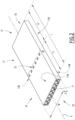
- the mouthpiece 32 is designed to be fixed on or be received in an insertion opening 36 formed at one of the ends of the housing 34. This opening 36 extends perpendicularly to the device axis Y as it is shown on Figure 5 where the mouthpiece 32 is removed from the housing 34.
- the housing 34 may for example form a substantially rectangular shape with rounded edges.
- the housing 34 with the mouthpiece 32 form at least four side walls 40.
- the housing 34 can have a round cross-sectional shape. In this case, it can form with the mouthpiece 32 only one side wall 40.
- the housing 34 can be sealed at the end opposite to the insertion opening 36 receiving the mouthpiece 32.
- the housing 34 can be formed from a single piece or several assembled pieces made of any suitable material like aluminium or plastic.
- the material of the housing 34 can be a thermally conductive material. In some other embodiments, it can be a thermally insulating material.
- the housing 34 can form on the corresponding part of the device side wall 40 one or several openings suitable for arranging control and/or visual elements.
- such element may comprise control buttons, touch panels, screens, LEDs, etc.
- the housing 34 forms a slot opening 42 receiving for example a LED indicating at least an ON state of the device 10. It can also indicate for example a battery law state, an error state, etc.
- the housing 34 delimits an internal space of the device 10 receiving various elements designed to carry out different functionalities of the device 10.
- This internal space can for example receive a battery for powering the device 10, a control module for controlling the operation of the device 10, a heating chamber 45 for heating the aerosol generating substrate 12 and at least one heating element 47 for heating the heating chamber 45.
- a heating chamber 45 for heating the aerosol generating substrate 12
- at least one heating element 47 for heating the heating chamber 45.
- only the heating chamber 45 and the heating element 47 will be explained in further detail in reference to Figures 5 to 9 .
- FIG. 3 shows in more detail the mouthpiece 32.
- the mouthpiece 32 is delimited by an internal surface 56 intended to face the insertion opening 36 while assembling the mouthpiece 32 with the housing 34, and an external surface 57 intended to form with the housing 34 at least one side wall 40 of the device 10.
- An external border 59 of the internal surface 56 is designed to be in a tight contact with a part of an internal border of the insertion opening 36 to fix the mouthpiece 32 inside the insertion opening 36.
- the external surface 57 has an appropriate shape to be in contact with the user's mouth and/or lips.
- Each side of the external surface 57 can be formed as an extension of the corresponding side of the housing to form an almost continuous side wall 40 of the device 10. Particularly, in this case, a discontinuity can be formed in the transition zone between the mouthpiece 32 and the housing 34.
- the mouthpiece 32 is crossed by a through-hole 60 extending along the device axis Y between a recess portion 62 and a flow outlet 64.
- the through-hole 60 is designed to receive the mouthpiece part 16 of the aerosol generating substrate 12 so as the substrate axis X coincides with the device axis Y.
- the through-hole 60 has the same cross-sectional shape as the aerosol generating substrate 12 and defines internal dimensions slightly greater than the external dimensions of the mouthpiece part 16 of the aerosol generating substrate 12.
- the through-hole 60 defines a rectangular cross-section to be able to receive the mouthpiece part 16 of the aerosol generating substrate 12 shown on Figure 2 .
- the through-hole 60 may have variable cross-sectional dimensions.
- the through-hole 60 can have gradually decreasing cross-sectional dimensions (notably the width) from the recess portion 62 to the flow outlet 64.
- the through-hole 60 and the mouthpiece part 16 of the aerosol generating substrate 12 can have the same length measured respectfully according to the device axis Y and the substrate axis X.
- the length of the mouthpiece part 16 of the aerosol generating substrate 12 can be less than the length of the through-hole 60 so as the mouth end 20 of the aerosol generating substrate 12 can be flushed at the flow outlet 64.
- the recess portion 62 corresponds to a cavity formed in both internal and external surfaces 56, 57 of the mouthpiece 32.
- This cavity can be formed by a first opening extending on the internal surface 56 on one side of the through-hole 60 from the border 59 to this through-hole 60 and a second opening extending on the external surface 57 from the border following d% of the length of the mouthpiece 32 measured according to the device axis Y.
- the value d can be less than 25, advantageously less than 10 and more advantageously less than 5.
- the recess portion 62 forms an opening 66 forming a flow inlet 66 as shown on Figure 4 .
- the flow inlet 66 is formed on a side wall 40 of the device 10 in a transition zone between the mouthpiece 32 and the housing 34.
- the aerosol generating substrate 12 comprises the venting holes 22
- at least some of these venting holes 22 are arranged to face the flow inlet 66.
- the heating chamber 45 forms a cup-shaped heating chamber extending along the device axis Y between an open end 70 and a sealed end 71.
- the heating chamber 45 is designed to receive the heater part 15 of the aerosol generating substrate 12.
- the heating chamber 45 defines substantially the same cross-sectional shape as the aerosol generating substrate 12.
- the heating chamber 45 defines a rectangular cross-sectional shape with two parallel chamber lateral walls 73A, 73B and two parallel chamber contact walls 74A, 74B.
- the heating chamber 45 also defines a distal wall 75 arranged perpendicularly to the device axis Y and sealing the sealed end 71.
- the distal wall 75 is adjacent to each of the walls 73A, 73B, 74A, 74B so as to seal the chamber at the sealed end 71 and thus, form a cup shape of the chamber opening at the open end 70.
- the only air permeable opening of the chamber 45 is formed at the open end 70.
- Each of the walls 73A, 73B, 74A, 74B, 75 can be made from a thermally conductive material like a metal. Additionally, at least some of the walls 73A, 73B, 74A, 74B, 75 or all of these walls can form a single piece.
- the internal dimensions of the heating chamber 45 are defined by the length L3 measured according the device axis Y, the width W3 measured as the distance between the chamber lateral walls 73A, 73B and the depth D3 measured as the distance between the chamber contact walls 74A, 74B. These internal dimensions L3, W3, D3 are chosen basing on the external dimensions L2, W, D of the heater part 15 of the aerosol generating substrate 12.
- the depth D3 of the heating chamber 45 is chosen slightly greater than the depth D of the aerosol generating substrate 12 or substantially equal to this depth D.
- the substrate contact walls 14A, 14B can be in contact with the chamber contact walls 74A, 74B when the heater part 15 of the of the aerosol generating substrate 12 is received inside the heating chamber 45.
- the chamber contact walls 74A, 74B are in a tight contact with the substrate contact walls 14A, 14B.
- the depth D3 of the heating chamber 45 can be even slightly less than the normal depth D of the aerosol generating substrate 12.
- the heating chamber 45 and/or the mouthpiece 32 is(are) configured to compress the heater part 15 of the aerosol generating substrate 12 by exerting force on the substrate contact walls 14A, 14B. This makes it possible to improve the tight contact between the corresponding contact walls of the heating chamber 45 and the substrate 12 and thus, to improve heat transfer between these walls.
- the width W3 of the heating chamber 45 is chosen so as at least one pair of facing lateral walls 73A, 13A or 73B, 13B of the heating chamber 45 and the aerosol generating substrate 12 forms an airflow channel between them.
- the width W3 of the heating chamber 45 is chosen so as each pair of facing lateral walls 73A, 13A or 73B, 13B of the heating chamber 45 and the aerosol generating substrate 12 forms an airflow channel between them.
- the distance d1 may for example be chosen substantially equal to the depth D3 of the heating chamber 45.
- an airflow channel of substantially square cross-section is formed along the device axis Y on either lateral side of the aerosol generating substrate 12.
- the distance d1 may be chosen equal to any other value depending on the flow rate required inside the aerosol generating substrate 12 while its heating.
- the length L3 of the heating chamber 45 is chosen so as to receive entirely the heating part 15 of the aerosol generating substrate 12 and form stopping means 80 at the sealed end 71 of the heating chamber 45.
- the length L3 is chosen to be strictly greater than the length L2 of the heater part 15 of the aerosol generating substrate 12.
- the stopping means 80 are configured to prevent contact of the abutting end 18 of the aerosol generating substrate 12 with the distal wall 75 of the heating chamber 45.
- the stopping means 80 are configured to create an airflow channel connecting each of the airflow channels formed between the chamber lateral walls 73A, 73B and the aerosol generating substrate 12, with each airflow channel formed inside the aerosol generating substrate 12.
- the stopping means 80 are formed by a rounded shape of the distal wall 75.
- the stopping means 80 are formed by at least on rib protruding axially from the distal wall 75.
- the heating element 47 is arranged in contact with one of the chamber contact walls 74A, 74B outside of the heating chamber 45. Particularly, in the example of these Figures, the heating element 47 is arranged adjacent to an outer surface of the chamber contact wall 74A.
- the heating element 47 may comprise a polyimide film heater extending along substantially the total area of said outer surface of the chamber contact wall 74A or only along a part of this surface. In this last case, said part may form a width substantially equal to the width W of the aerosol generating substrate 12.
- the heating element 45 is powered by the battery and controlled by the control module of the aerosol generating device 10.
- the aerosol generating device 10 may comprise two heating elements 47, each heating element 47 being attached on the outer surface of one of the chamber contact walls 74A, 74B. Additionally, according to some embodiments, the aerosol generating device 10 further comprises an insulator arranged between the or each heating element 47 and an inner surface of the housing 34. The same insulator may also be arranged between an outer surface of each of the chamber lateral walls 73A, 73B and the inner surface of the housing 34.
- the aerosol generating substrate 12 is extracted from the device 10.
- the user first takes off the mouthpiece 32 from the housing 34.
- the user inserts the heater part 15 of the aerosol generating substrate 12 into the heating chamber 45 until the abutting end 18 of the substrate 12 abuts against the stopping means 80 of the heating chamber 45.
- the user fixes the mouthpiece 32 on the housing 34 by sliding the mouthpiece part 16 of the aerosol generating substrate 12 inside the through-hole 60 of the mouthpiece 32 and by inserting the mouthpiece 32 in the insertion opening 36 of the housing 34.
- the user can activate the operation of the aerosol generating device 10 by actuating for example an ON button or by performing a puff. This creates an airflow in an airflow path formed inside the device between the flow inlet 66 and the flow outlet 64 as it is shown on Figure 4 .
- the airflow path inside the aerosol generating device 10 comprises an upstream portion extending from the flow inlet 66 until the abutting end 18 of the aerosol generating substrate 12, a transition portion at the sealed end 71 of the heating chamber 45 and a downstream portion extending from said abutting end 18 until the flow outlet 64 through the aerosol generating substrate 12.
- the upstream portion extends through the open end 70 of the heating chamber 45 and then, between each pair of lateral walls 73A, 13A and 73B, 13B of the heating chamber 45 and the aerosol generating substrate 12, as it is shown on Figure 6 .
- the transition portion forms a "U" turn inside the heating chamber 45 as it is shown on Figures 8 and 9 and forces the flow to flow inside the aerosol generating substrate 12.
- the downstream portion extends advantageously only inside the aerosol generating substrate 12. In the case when the aerosol generating substrate comprises the venting holes 22, the flow flowing in the downstream portion can further comprise fresh air entered through these holes 22.
- the heater part 15 of the aerosol generating substrate 12 may have for example a flat-plate shape with slotted grooves on both opposite surfaces.
- the slotted grooves may form at least part of the downstream portion.
- FIG 10 shows an aerosol generating device 110 according to a second embodiment.
- This aerosol generating device 110 is similar to the aerosol generating device 10 and notably, is configured to operate with the same aerosol generating substrate 12 shown on Figure 2 .
- An assembly comprises the aerosol generating device 110 and the aerosol generating substrate 12.
- the aerosol generating substrate 12 is in particular inserted into the aerosol generating device 110.
- the assembly comprises the aerosol generating substrate 12 being inserted into a heating chamber of the aerosol generating device 110.
- the aerosol generating device 110 also comprises a device body 130 defining at least one side wall 140 of the device 110 and comprising a mouthpiece 132 and a housing 134 having similar external shapes as respectfully the mouthpiece 32 and the housing 34 explained before in relation with the first embodiment.
- the mouthpiece 132 and the housing 134 form a single piece.
- the aerosol generating substrate can for example be loaded directly from an opening 164 of the mouthpiece 132.
- This opening 164 also forms a flow outlet 164 similar to the flow outlet 64 explained before.
- the aerosol generating substrate 12 can be extracted from the same opening 164 using for example an internal extracting mechanism which can be actuated by an actuator 142 arranged on the side wall 140.
- the or each side wall 140 has for example a smooth external surface and defines a transition zone between the mouthpiece 132 and the housing 134. Furthermore, as in the previous case, the transition zone defines an opening 166 forming a flow inlet 166.
- the interior part of the aerosol generating device 110 is similar to the interior part of the aerosol generating device 10 explained above.
- the aerosol generating device 110 comprises the same heating chamber as the heating chamber 45 explained before.
- the flow inlet 166 is in a fluid communication with each of the airflow channels formed between the lateral walls of the heating chamber and the aerosol generating substrate. Additionally, as in the previous embodiment, the flow is forced inside the chamber to follow a "U" turn to flow inside the aerosol generating substrate until the flow outlet 164.
- the operation of the aerosol generating device 110 is also similar to the operation of the aerosol generating device 10 explained above.
- the unique difference consists in the way of loading/extracting of the aerosol generating substrate 12.
- FIG 11 shows an aerosol generating device 210 according to a third embodiment.
- This aerosol generating device 210 is similar to the aerosol generating device 110 according to the second embodiment and notably, is configured to operate with the same aerosol generating substrate 12 shown on Figure 2 .
- An assembly comprises the aerosol generating device 210 and the aerosol generating substrate 12.
- the aerosol generating substrate 12 is in particular inserted into the aerosol generating device 210.
- the assembly comprises the aerosol generating substrate 12 being inserted into a heating chamber of the aerosol generating device 210.
- the aerosol generating device 210 according to the third embodiment also comprises a device body 230 defining at least one side wall 240 of the device 210. Contrary to the previous embodiments, the device body 230 according to the third embodiment does not define a mouthpiece. As it is shown on Figure 11 , a mouthpiece is formed by at least a part of the mouthpiece part 16 of the aerosol generating substrate 12.
- the device body 230 forms an insertion opening 236 extending perpendicularly to the device axis Y at one of the ends of the device body 230.
- the opening 236 is suitable to receive at least the heater part 15 of the aerosol generating substrate 12.
- the opening 236 communicates with a heating chamber arranged inside the device body 230. This heating chamber is similar to the heating chamber explained above and notably, is adapted to receive the heater part 15 of the aerosol generating substrate 12.
- the mouthpiece part 16 of the aerosol generating substrate 12 protrudes from the opening 236 forming thus a mouthpiece.
- this protruding part of the aerosol generating substrate 12 is designed to be in contact with the user's lips and mouth while using the device 210 and forms a flow outlet 264.
- a flow inlet 266 is formed on the side wall 240 of the device body 230. This flow inlet 266 is in a fluid communication with each of the airflow channels formed between the lateral walls of the heating chamber and the aerosol generating substrate 12. Additionally, as in the previous cases, the flow is forced inside the chamber to follow a "U" turn to flow inside the aerosol generating substrate 12 until the flow outlet 264.
- venting holes 22 may be arranged on the protruding part of the mouthpiece part 16 of the substrate 12 as it is shown on Figure 11 .
- the venting holes 22 are arranged on the part of the mouthpiece part 16 of the substrate 12 which is received inside the device body 230, advantageously to face the flow inlet 266 as in the second embodiment.
- an actuator 242 may be arranged on the side wall 240 of the device 210 to facilitate the extraction of the aerosol generating substrate 12.
- no actuator is provided on the side wall and the substrate 12 is extracted by pulling its protruding part.
- An aerosol generating device according to a fourth embodimen has the same structure as the aerosol generating device 110 according to the second embodiment, the only difference being in the nature of the substrate 12 that the aerosol generating device according to the fourth embodiment is able to receive.
- An assembly comprises the aerosol generating device according to the fourth embodiment and the aerosol generating substrate.
- the aerosol generating device according to the fourth embodiment can be adapted to receive aerosol generating substrates of different lengths.
- the aerosol generating device according to the fourth embodiment may be adapted to receive an aerosol generating substrate of a "normal" length, i.e. a substrate similar to the substrate of Figure 2 .
- this aerosol generating device may operate like the aerosol generating device 110 according to the second embodiment, i.e. it may form a mouthpiece making a part of the device body.
- the aerosol generating device according to the fourth embodiment may also be adapted to receive an elongated aerosol generating substrate.
- the substrate can protrude from the device body and form a mouthpiece.
- the aerosol generating device according to the fourth embodiment may operate as the aerosol generating device 210 according to the third embodiment.
Landscapes
- Health & Medical Sciences (AREA)
- Engineering & Computer Science (AREA)
- Animal Behavior & Ethology (AREA)
- Anesthesiology (AREA)
- Biomedical Technology (AREA)
- Heart & Thoracic Surgery (AREA)
- Hematology (AREA)
- Life Sciences & Earth Sciences (AREA)
- General Health & Medical Sciences (AREA)
- Public Health (AREA)
- Veterinary Medicine (AREA)
- Pulmonology (AREA)
- Bioinformatics & Cheminformatics (AREA)
- Containers And Packaging Bodies Having A Special Means To Remove Contents (AREA)
Applications Claiming Priority (2)
| Application Number | Priority Date | Filing Date | Title |
|---|---|---|---|
| EP21173025 | 2021-05-10 | ||
| PCT/EP2022/062498 WO2022238337A1 (en) | 2021-05-10 | 2022-05-09 | Aerosol generating device comprising a cup-shaped heating chamber defining an open end and a sealed end |
Publications (2)
| Publication Number | Publication Date |
|---|---|
| EP4337042A1 EP4337042A1 (en) | 2024-03-20 |
| EP4337042B1 true EP4337042B1 (en) | 2025-01-29 |
Family
ID=76011678
Family Applications (1)
| Application Number | Title | Priority Date | Filing Date |
|---|---|---|---|
| EP22728452.8A Active EP4337042B1 (en) | 2021-05-10 | 2022-05-09 | Aerosol generating device comprising a cup-shaped heating chamber defining an open end and a sealed end |
Country Status (6)
| Country | Link |
|---|---|
| US (1) | US20240245130A1 (https=) |
| EP (1) | EP4337042B1 (https=) |
| JP (1) | JP7830511B2 (https=) |
| KR (1) | KR20240007180A (https=) |
| TW (1) | TW202245630A (https=) |
| WO (1) | WO2022238337A1 (https=) |
Families Citing this family (10)
| Publication number | Priority date | Publication date | Assignee | Title |
|---|---|---|---|---|
| US20240415168A1 (en) * | 2022-01-05 | 2024-12-19 | Jt International S.A. | Flat-Shaped Tobacco Article and Associated Aerosol Generating Device with Improved Heat Transfer |
| CN120435237A (zh) * | 2022-12-23 | 2025-08-05 | 菲利普莫里斯生产公司 | 气溶胶生成制品和系统 |
| CN118370403A (zh) * | 2023-01-20 | 2024-07-23 | 思摩尔国际控股有限公司 | 一种气溶胶生成基质及气溶胶生成制品 |
| CN120936259A (zh) * | 2023-04-21 | 2025-11-11 | 菲利普莫里斯生产公司 | 用于平坦的薄型消耗品的气溶胶生成装置 |
| EP4701456A1 (en) * | 2023-04-28 | 2026-03-04 | JT International SA | Tobacco article for a heat-not-burn aerosol generating device and associated manufacturing method |
| KR20250168487A (ko) * | 2023-05-15 | 2025-12-02 | 제이티 인터내셔널 소시에떼 아노님 | 에어로졸 생성 장치의 가열기 조립체용 하우징 |
| WO2025003301A1 (en) * | 2023-06-27 | 2025-01-02 | Jt International Sa | Aerosol generating device comprising a heating cup |
| WO2025056624A2 (en) * | 2023-09-12 | 2025-03-20 | Nicoventures Trading Limited | Article for an aerosol provision device |
| CN121772852A (zh) * | 2023-09-14 | 2026-03-31 | 菲利普莫里斯生产公司 | 具有蛇形导电轨道的加热器组件 |
| WO2026003111A1 (en) * | 2024-06-25 | 2026-01-02 | Philip Morris Products S.A. | Aerosol-forming article and aerosol-forming device |
Citations (1)
| Publication number | Priority date | Publication date | Assignee | Title |
|---|---|---|---|---|
| EP3462939B1 (en) * | 2016-05-25 | 2021-05-19 | Philip Morris Products S.A. | Aerosol-generating article comprising a piston and aerosol-generating device |
Family Cites Families (8)
| Publication number | Priority date | Publication date | Assignee | Title |
|---|---|---|---|---|
| US8991402B2 (en) | 2007-12-18 | 2015-03-31 | Pax Labs, Inc. | Aerosol devices and methods for inhaling a substance and uses thereof |
| DE202014003760U1 (de) | 2013-05-02 | 2014-08-08 | Jt International S.A. | Vaporisierbarer Materialstopfen und Kapsel |
| EP3089599B1 (en) | 2013-12-31 | 2019-02-13 | Philip Morris Products S.a.s. | An aerosol-generating device, and a capsule for use in an aerosol-generating device |
| US9380813B2 (en) * | 2014-02-11 | 2016-07-05 | Timothy McCullough | Drug delivery system and method |
| CA2951396A1 (en) | 2014-07-11 | 2016-01-14 | Philip Morris Products S.A. | Aerosol-generating system comprising a removable heater |
| EP3711592A1 (en) * | 2019-03-21 | 2020-09-23 | Nerudia Limited | Aerosol delivery system |
| WO2020074604A1 (en) * | 2018-10-12 | 2020-04-16 | Jt International S.A. | Aerosol generation device and heating chamber therefor |
| EA202193242A1 (ru) * | 2019-05-29 | 2022-03-18 | ДжейТи ИНТЕРНЕШНЛ СА | Картридж для устройства, генерирующего аэрозоль |
-
2022
- 2022-05-09 EP EP22728452.8A patent/EP4337042B1/en active Active
- 2022-05-09 JP JP2023567151A patent/JP7830511B2/ja active Active
- 2022-05-09 WO PCT/EP2022/062498 patent/WO2022238337A1/en not_active Ceased
- 2022-05-09 US US18/560,012 patent/US20240245130A1/en active Pending
- 2022-05-09 KR KR1020237041005A patent/KR20240007180A/ko active Pending
- 2022-05-10 TW TW111117550A patent/TW202245630A/zh unknown
Patent Citations (1)
| Publication number | Priority date | Publication date | Assignee | Title |
|---|---|---|---|---|
| EP3462939B1 (en) * | 2016-05-25 | 2021-05-19 | Philip Morris Products S.A. | Aerosol-generating article comprising a piston and aerosol-generating device |
Also Published As
| Publication number | Publication date |
|---|---|
| KR20240007180A (ko) | 2024-01-16 |
| WO2022238337A1 (en) | 2022-11-17 |
| US20240245130A1 (en) | 2024-07-25 |
| TW202245630A (zh) | 2022-12-01 |
| EP4337042A1 (en) | 2024-03-20 |
| JP7830511B2 (ja) | 2026-03-16 |
| JP2024518050A (ja) | 2024-04-24 |
Similar Documents
| Publication | Publication Date | Title |
|---|---|---|
| EP4337042B1 (en) | Aerosol generating device comprising a cup-shaped heating chamber defining an open end and a sealed end | |
| EP4337045B1 (en) | Aerosol generating device comprising two heating elements | |
| US20240349802A1 (en) | Aerosol Generating Device Comprising a Flat-Shaped Heating Chamber and Associated Aerosol Generating Assembly | |
| US20240415167A1 (en) | Flat-Shaped Tobacco Article Comprising a First Gap and a Second Gap, and Associated Aerosol Generating Device and Assembly | |
| US20240237735A1 (en) | Aerosol Generating Device Comprising a Pushing Bar | |
| EP4422439B1 (en) | Aerosol generating device with a heating chamber adapted for convection heating | |
| US20250185717A1 (en) | Aerosol Generating Device Comprising Leakage Preventing Means and Associated Aerosol Generating Assembly | |
| US20240268452A1 (en) | Flat Tobacco Article Comprising at Least Two Layers and Aerosol Generating Device with Such an Article | |
| US20240381939A1 (en) | Aerosol Generating Device with Optimized Air Inlet Arrangement | |
| US20240423262A1 (en) | Flat-Shaped Tobacco Article Comprising a Gap, and Associated Aerosol Generating Device and Assembly | |
| EP4687520A1 (en) | Aerosol generating device comprising a thermal break and associated aerosol generating assembly | |
| EP4661704A1 (en) | Aerosol generating assembly comprising a cavity configured to receive an aerosol generating article | |
| WO2024223829A1 (en) | Tobacco article for a heat-not-burn aerosol generating device and associated aerosol generating system | |
| WO2024240644A1 (en) | Aerosol generating device configured to operate with a flat-shaped tobacco article and assembly comprising such aerosol generating device | |
| EP4701466A1 (en) | Tobacco article for a heat-not-burn aerosol generating device and associated aerosol generating system | |
| EP4701465A1 (en) | Tobacco article for a heat-not-burn aerosol generating device and associated aerosol generating system |
Legal Events
| Date | Code | Title | Description |
|---|---|---|---|
| STAA | Information on the status of an ep patent application or granted ep patent |
Free format text: STATUS: UNKNOWN |
|
| STAA | Information on the status of an ep patent application or granted ep patent |
Free format text: STATUS: THE INTERNATIONAL PUBLICATION HAS BEEN MADE |
|
| PUAI | Public reference made under article 153(3) epc to a published international application that has entered the european phase |
Free format text: ORIGINAL CODE: 0009012 |
|
| STAA | Information on the status of an ep patent application or granted ep patent |
Free format text: STATUS: REQUEST FOR EXAMINATION WAS MADE |
|
| 17P | Request for examination filed |
Effective date: 20231109 |
|
| AK | Designated contracting states |
Kind code of ref document: A1 Designated state(s): AL AT BE BG CH CY CZ DE DK EE ES FI FR GB GR HR HU IE IS IT LI LT LU LV MC MK MT NL NO PL PT RO RS SE SI SK SM TR |
|
| DAV | Request for validation of the european patent (deleted) | ||
| DAX | Request for extension of the european patent (deleted) | ||
| REG | Reference to a national code |
Ref country code: DE Ref legal event code: R079 Free format text: PREVIOUS MAIN CLASS: A24F0040200000 Ipc: A24F0040400000 Ref country code: DE Ref legal event code: R079 Ref document number: 602022010221 Country of ref document: DE Free format text: PREVIOUS MAIN CLASS: A24F0040200000 Ipc: A24F0040400000 |
|
| GRAP | Despatch of communication of intention to grant a patent |
Free format text: ORIGINAL CODE: EPIDOSNIGR1 |
|
| STAA | Information on the status of an ep patent application or granted ep patent |
Free format text: STATUS: GRANT OF PATENT IS INTENDED |
|
| RIC1 | Information provided on ipc code assigned before grant |
Ipc: A61M 15/06 20060101ALN20240828BHEP Ipc: A61M 15/00 20060101ALN20240828BHEP Ipc: A61M 11/04 20060101ALN20240828BHEP Ipc: A24D 1/20 20200101ALI20240828BHEP Ipc: A24F 40/46 20200101ALI20240828BHEP Ipc: A24F 40/20 20200101ALI20240828BHEP Ipc: A24F 40/40 20200101AFI20240828BHEP |
|
| INTG | Intention to grant announced |
Effective date: 20240911 |
|
| GRAS | Grant fee paid |
Free format text: ORIGINAL CODE: EPIDOSNIGR3 |
|
| GRAA | (expected) grant |
Free format text: ORIGINAL CODE: 0009210 |
|
| STAA | Information on the status of an ep patent application or granted ep patent |
Free format text: STATUS: THE PATENT HAS BEEN GRANTED |
|
| AK | Designated contracting states |
Kind code of ref document: B1 Designated state(s): AL AT BE BG CH CY CZ DE DK EE ES FI FR GB GR HR HU IE IS IT LI LT LU LV MC MK MT NL NO PL PT RO RS SE SI SK SM TR |
|
| REG | Reference to a national code |
Ref country code: GB Ref legal event code: FG4D |
|
| REG | Reference to a national code |
Ref country code: CH Ref legal event code: EP |
|
| REG | Reference to a national code |
Ref country code: DE Ref legal event code: R096 Ref document number: 602022010221 Country of ref document: DE |
|
| REG | Reference to a national code |
Ref country code: IE Ref legal event code: FG4D |
|
| REG | Reference to a national code |
Ref country code: NL Ref legal event code: MP Effective date: 20250129 |
|
| PG25 | Lapsed in a contracting state [announced via postgrant information from national office to epo] |
Ref country code: NL Free format text: LAPSE BECAUSE OF FAILURE TO SUBMIT A TRANSLATION OF THE DESCRIPTION OR TO PAY THE FEE WITHIN THE PRESCRIBED TIME-LIMIT Effective date: 20250129 |
|
| PG25 | Lapsed in a contracting state [announced via postgrant information from national office to epo] |
Ref country code: RS Free format text: LAPSE BECAUSE OF FAILURE TO SUBMIT A TRANSLATION OF THE DESCRIPTION OR TO PAY THE FEE WITHIN THE PRESCRIBED TIME-LIMIT Effective date: 20250429 |
|
| PG25 | Lapsed in a contracting state [announced via postgrant information from national office to epo] |
Ref country code: FI Free format text: LAPSE BECAUSE OF FAILURE TO SUBMIT A TRANSLATION OF THE DESCRIPTION OR TO PAY THE FEE WITHIN THE PRESCRIBED TIME-LIMIT Effective date: 20250129 |
|
| PG25 | Lapsed in a contracting state [announced via postgrant information from national office to epo] |
Ref country code: PL Free format text: LAPSE BECAUSE OF FAILURE TO SUBMIT A TRANSLATION OF THE DESCRIPTION OR TO PAY THE FEE WITHIN THE PRESCRIBED TIME-LIMIT Effective date: 20250129 |
|
| PGFP | Annual fee paid to national office [announced via postgrant information from national office to epo] |
Ref country code: DE Payment date: 20250521 Year of fee payment: 4 |
|
| PG25 | Lapsed in a contracting state [announced via postgrant information from national office to epo] |
Ref country code: ES Free format text: LAPSE BECAUSE OF FAILURE TO SUBMIT A TRANSLATION OF THE DESCRIPTION OR TO PAY THE FEE WITHIN THE PRESCRIBED TIME-LIMIT Effective date: 20250129 |
|
| REG | Reference to a national code |
Ref country code: LT Ref legal event code: MG9D |
|
| PG25 | Lapsed in a contracting state [announced via postgrant information from national office to epo] |
Ref country code: IS Free format text: LAPSE BECAUSE OF FAILURE TO SUBMIT A TRANSLATION OF THE DESCRIPTION OR TO PAY THE FEE WITHIN THE PRESCRIBED TIME-LIMIT Effective date: 20250529 Ref country code: NO Free format text: LAPSE BECAUSE OF FAILURE TO SUBMIT A TRANSLATION OF THE DESCRIPTION OR TO PAY THE FEE WITHIN THE PRESCRIBED TIME-LIMIT Effective date: 20250429 |
|
| PGFP | Annual fee paid to national office [announced via postgrant information from national office to epo] |
Ref country code: IT Payment date: 20250531 Year of fee payment: 4 |
|
| REG | Reference to a national code |
Ref country code: AT Ref legal event code: MK05 Ref document number: 1762532 Country of ref document: AT Kind code of ref document: T Effective date: 20250129 |
|
| PG25 | Lapsed in a contracting state [announced via postgrant information from national office to epo] |
Ref country code: HR Free format text: LAPSE BECAUSE OF FAILURE TO SUBMIT A TRANSLATION OF THE DESCRIPTION OR TO PAY THE FEE WITHIN THE PRESCRIBED TIME-LIMIT Effective date: 20250129 |
|
| PG25 | Lapsed in a contracting state [announced via postgrant information from national office to epo] |
Ref country code: PT Free format text: LAPSE BECAUSE OF FAILURE TO SUBMIT A TRANSLATION OF THE DESCRIPTION OR TO PAY THE FEE WITHIN THE PRESCRIBED TIME-LIMIT Effective date: 20250529 Ref country code: LV Free format text: LAPSE BECAUSE OF FAILURE TO SUBMIT A TRANSLATION OF THE DESCRIPTION OR TO PAY THE FEE WITHIN THE PRESCRIBED TIME-LIMIT Effective date: 20250129 |
|
| PG25 | Lapsed in a contracting state [announced via postgrant information from national office to epo] |
Ref country code: BG Free format text: LAPSE BECAUSE OF FAILURE TO SUBMIT A TRANSLATION OF THE DESCRIPTION OR TO PAY THE FEE WITHIN THE PRESCRIBED TIME-LIMIT Effective date: 20250129 Ref country code: GR Free format text: LAPSE BECAUSE OF FAILURE TO SUBMIT A TRANSLATION OF THE DESCRIPTION OR TO PAY THE FEE WITHIN THE PRESCRIBED TIME-LIMIT Effective date: 20250430 |
|
| PGFP | Annual fee paid to national office [announced via postgrant information from national office to epo] |
Ref country code: CH Payment date: 20250601 Year of fee payment: 4 |
|
| PG25 | Lapsed in a contracting state [announced via postgrant information from national office to epo] |
Ref country code: AT Free format text: LAPSE BECAUSE OF FAILURE TO SUBMIT A TRANSLATION OF THE DESCRIPTION OR TO PAY THE FEE WITHIN THE PRESCRIBED TIME-LIMIT Effective date: 20250129 |
|
| PG25 | Lapsed in a contracting state [announced via postgrant information from national office to epo] |
Ref country code: SE Free format text: LAPSE BECAUSE OF FAILURE TO SUBMIT A TRANSLATION OF THE DESCRIPTION OR TO PAY THE FEE WITHIN THE PRESCRIBED TIME-LIMIT Effective date: 20250129 |
|
| PG25 | Lapsed in a contracting state [announced via postgrant information from national office to epo] |
Ref country code: SM Free format text: LAPSE BECAUSE OF FAILURE TO SUBMIT A TRANSLATION OF THE DESCRIPTION OR TO PAY THE FEE WITHIN THE PRESCRIBED TIME-LIMIT Effective date: 20250129 |
|
| PG25 | Lapsed in a contracting state [announced via postgrant information from national office to epo] |
Ref country code: DK Free format text: LAPSE BECAUSE OF FAILURE TO SUBMIT A TRANSLATION OF THE DESCRIPTION OR TO PAY THE FEE WITHIN THE PRESCRIBED TIME-LIMIT Effective date: 20250129 |
|
| PG25 | Lapsed in a contracting state [announced via postgrant information from national office to epo] |
Ref country code: EE Free format text: LAPSE BECAUSE OF FAILURE TO SUBMIT A TRANSLATION OF THE DESCRIPTION OR TO PAY THE FEE WITHIN THE PRESCRIBED TIME-LIMIT Effective date: 20250129 Ref country code: CZ Free format text: LAPSE BECAUSE OF FAILURE TO SUBMIT A TRANSLATION OF THE DESCRIPTION OR TO PAY THE FEE WITHIN THE PRESCRIBED TIME-LIMIT Effective date: 20250129 |
|
| PG25 | Lapsed in a contracting state [announced via postgrant information from national office to epo] |
Ref country code: RO Free format text: LAPSE BECAUSE OF FAILURE TO SUBMIT A TRANSLATION OF THE DESCRIPTION OR TO PAY THE FEE WITHIN THE PRESCRIBED TIME-LIMIT Effective date: 20250129 |
|
| PG25 | Lapsed in a contracting state [announced via postgrant information from national office to epo] |
Ref country code: SK Free format text: LAPSE BECAUSE OF FAILURE TO SUBMIT A TRANSLATION OF THE DESCRIPTION OR TO PAY THE FEE WITHIN THE PRESCRIBED TIME-LIMIT Effective date: 20250129 |
|
| REG | Reference to a national code |
Ref country code: DE Ref legal event code: R097 Ref document number: 602022010221 Country of ref document: DE |
|
| PLBE | No opposition filed within time limit |
Free format text: ORIGINAL CODE: 0009261 |
|
| STAA | Information on the status of an ep patent application or granted ep patent |
Free format text: STATUS: NO OPPOSITION FILED WITHIN TIME LIMIT |
|
| 26N | No opposition filed |
Effective date: 20251030 |
|
| PG25 | Lapsed in a contracting state [announced via postgrant information from national office to epo] |
Ref country code: LU Free format text: LAPSE BECAUSE OF NON-PAYMENT OF DUE FEES Effective date: 20250509 |
|
| REG | Reference to a national code |
Ref country code: BE Ref legal event code: MM Effective date: 20250531 |
|
| PG25 | Lapsed in a contracting state [announced via postgrant information from national office to epo] |
Ref country code: MC Free format text: LAPSE BECAUSE OF FAILURE TO SUBMIT A TRANSLATION OF THE DESCRIPTION OR TO PAY THE FEE WITHIN THE PRESCRIBED TIME-LIMIT Effective date: 20250129 |
|
| PG25 | Lapsed in a contracting state [announced via postgrant information from national office to epo] |
Ref country code: IE Free format text: LAPSE BECAUSE OF NON-PAYMENT OF DUE FEES Effective date: 20250509 |
|
| PG25 | Lapsed in a contracting state [announced via postgrant information from national office to epo] |
Ref country code: BE Free format text: LAPSE BECAUSE OF NON-PAYMENT OF DUE FEES Effective date: 20250531 |
|
| PG25 | Lapsed in a contracting state [announced via postgrant information from national office to epo] |
Ref country code: FR Free format text: LAPSE BECAUSE OF NON-PAYMENT OF DUE FEES Effective date: 20250531 |