EP4336981A1 - Electric vehicle - Google Patents
Electric vehicle Download PDFInfo
- Publication number
- EP4336981A1 EP4336981A1 EP23174788.2A EP23174788A EP4336981A1 EP 4336981 A1 EP4336981 A1 EP 4336981A1 EP 23174788 A EP23174788 A EP 23174788A EP 4336981 A1 EP4336981 A1 EP 4336981A1
- Authority
- EP
- European Patent Office
- Prior art keywords
- case
- electronic component
- control board
- wall
- electric vehicle
- Prior art date
- Legal status (The legal status is an assumption and is not a legal conclusion. Google has not performed a legal analysis and makes no representation as to the accuracy of the status listed.)
- Pending
Links
Images


Classifications
-
- H—ELECTRICITY
- H05—ELECTRIC TECHNIQUES NOT OTHERWISE PROVIDED FOR
- H05K—PRINTED CIRCUITS; CASINGS OR CONSTRUCTIONAL DETAILS OF ELECTRIC APPARATUS; MANUFACTURE OF ASSEMBLAGES OF ELECTRICAL COMPONENTS
- H05K7/00—Constructional details common to different types of electric apparatus
- H05K7/20—Modifications to facilitate cooling, ventilating, or heating
- H05K7/20845—Modifications to facilitate cooling, ventilating, or heating for automotive electronic casings
- H05K7/20854—Heat transfer by conduction from internal heat source to heat radiating structure
-
- B—PERFORMING OPERATIONS; TRANSPORTING
- B62—LAND VEHICLES FOR TRAVELLING OTHERWISE THAN ON RAILS
- B62J—CYCLE SADDLES OR SEATS; AUXILIARY DEVICES OR ACCESSORIES SPECIALLY ADAPTED TO CYCLES AND NOT OTHERWISE PROVIDED FOR, e.g. ARTICLE CARRIERS OR CYCLE PROTECTORS
- B62J45/00—Electrical equipment arrangements specially adapted for use as accessories on cycles, not otherwise provided for
- B62J45/20—Cycle computers as cycle accessories
-
- H—ELECTRICITY
- H05—ELECTRIC TECHNIQUES NOT OTHERWISE PROVIDED FOR
- H05K—PRINTED CIRCUITS; CASINGS OR CONSTRUCTIONAL DETAILS OF ELECTRIC APPARATUS; MANUFACTURE OF ASSEMBLAGES OF ELECTRICAL COMPONENTS
- H05K5/00—Casings, cabinets or drawers for electric apparatus
- H05K5/0026—Casings, cabinets or drawers for electric apparatus provided with connectors and printed circuit boards [PCB], e.g. automotive electronic control units
-
- H—ELECTRICITY
- H05—ELECTRIC TECHNIQUES NOT OTHERWISE PROVIDED FOR
- H05K—PRINTED CIRCUITS; CASINGS OR CONSTRUCTIONAL DETAILS OF ELECTRIC APPARATUS; MANUFACTURE OF ASSEMBLAGES OF ELECTRICAL COMPONENTS
- H05K7/00—Constructional details common to different types of electric apparatus
- H05K7/20—Modifications to facilitate cooling, ventilating, or heating
- H05K7/2039—Modifications to facilitate cooling, ventilating, or heating characterised by the heat transfer by conduction from the heat generating element to a dissipating body
- H05K7/20436—Inner thermal coupling elements in heat dissipating housings, e.g. protrusions or depressions integrally formed in the housing
- H05K7/20445—Inner thermal coupling elements in heat dissipating housings, e.g. protrusions or depressions integrally formed in the housing the coupling element being an additional piece, e.g. thermal standoff
- H05K7/20472—Sheet interfaces
Definitions
- the present invention relates to an electric vehicle.
- a control unit for example, an electronic circuit device has been used on an electric vehicle.
- a patent document JP2005-129820A discloses the electronic circuit device.
- the electronic circuit device includes a case member, a control board and an electronic component.
- the case member includes an upper case and a lower case.
- An internal space is formed between the upper case and the lower case.
- the control board is mounted to the lower case in the internal space.
- the electronic component are mounted to the control board. Resin is filled in the internal space between the upper case and the electronic component and in the internal space between the upper case and the control board.
- An object of the present invention is to provide an electric vehicle which can suitably dissipate heat which is generated by an electronic component.
- An electric vehicle includes a vehicle body, a controlled portion and a control unit.
- the controlled portion is mounted to the vehicle body.
- the controlled portion electrically controlled.
- the control unit is configured to control the controlled unit.
- the control unit includes a case member, a control board, an electronic component and a supporting structure.
- the case member is mounted to the vehicle body.
- the case member forms an internal space.
- the control board is mounted to the case member in the internal space.
- the electronic component is mounted to the control board in the internal space.
- the supporting structure is provided on an inner surface of the case member. The supporting structure is configured to support the electronic component so that the electronic component is partially exposed in the internal space.
- the supporting structure of the control unit supports the electronic component so that the electronic component is partially exposed in the internal space.
- the electric vehicle can suitably dissipate heat of the electronic component.
- the case member can include a first wall portion and a second wall portion.
- the first wall portion has the inner surface which is disposed so as to face the control board.
- the second wall portion protrudes from the first wall portion toward the control board. The second wall portion configures the supporting structure.
- the electronic component can be suitably positioned without using a filler such as resin.
- the second wall portion can be formed on the first wall portion so as to surround a side surface of the electronic component. Thereby, the electronic component can be more suitably positioned.
- the side surface of the electronic component can be fixed to the second wall portion by an adhesive. Thereby, the electronic component can be more suitably positioned.
- the electric vehicle can further include a heat dissipation sheet disposed between the case member and the electronic component. Thereby, the electric vehicle can more suitably dissipate the heat of the electronic component.
- the case member can include a first case and a second case.
- the control board is mounted to the first case.
- the second case is mounted to the first case.
- the second case is configured to cover the control board and the electronic component.
- the supporting structure is provided on the second case.
- control board and the electronic component are mounted to the first case.
- the second case is mounted to the first case, so that the control board and the electronic component are easily disposed in the internal space between the first case and the second case in a state that the electronic component is supported by the supporting structure of the second case.
- the case member can include a first case and a second case.
- the control board is mounted to the first case.
- the second case is mounted to the first case.
- the second case is configured to cover the control board.
- the electronic component is disposed between the control board and the first case.
- the supporting structure is provided on the first case.
- the electronic component is disposed between the control board and the first case in a state where the supporting structure of the first case supports the electronic component.
- the second case is mounted to the first case, so that the control board and the electronic component can be easily disposed in the internal space between the first case and the second case in a state that the electronic component is supported by the supporting structure of the second case.
- an electric vehicle can suitably dissipate heat which is generated by an electronic component.
- FIG. 1 an example, in which the electric vehicle is a straddled vehicle 1, is shown.
- a vehicle, which is different from the straddled vehicle 1, can be used as long as the vehicle is an electric vehicle.
- a straddled vehicle 1 includes a vehicle body frame 2 (an example of a vehicle body), a steering device 3, a front wheel 5, and a rear wheel 6.
- the straddled vehicle 1 further includes an electric motor 7 (an example of a controlled portion), a control unit 8, and a heat dissipation sheet 9 (see FIG. 3 ).
- the straddled vehicle 1 includes a vehicle center plane H extending in a front-rear direction.
- a front side of a rider (a left side in FIG. 1 ), a rear side of the rider (a right side in FIG. 1 ), a left side of the rider (a right side in FIG. 2 ), and a right side of the rider (a left side in FIG. 2 ) respectively correspond to front, rear, left and right directions of the straddled vehicle 1, in a state where the rider is seated on a seat 10.
- a vehicle width direction W is defined as a direction perpendicular to the vehicle center plane H.
- the vehicle width direction W indicates the left-right direction with respect to the vehicle center plane H.
- An upper side of the rider corresponds to an upper direction of the straddled vehicle 1.
- a lower direction of the straddled vehicle 1 (a lower direction in FIGS. 1 and 2 ) is a direction opposite to the upper direction of the straddled vehicle 1.
- a side view of the straddled vehicle 1 shows a side view of the straddled vehicle 1 viewed from the left side or the right side.
- FIG. 1 shows the side view of the straddled vehicle 1 viewed from the left side.
- FIG. 2 shows the front view of the straddled vehicle 1 viewed from the front side.
- the vehicle body frame 2 includes a head pipe 11 and a main frame 12.
- the main frame 12 is connected to the head pipe 11.
- the vehicle body frame 2 includes the vehicle center plane H (see FIG. 2 ) that passes through the head pipe 11 in the front-rear direction.
- the steering device 3 includes a front fork 15, a steering shaft 16 and a handle member 17.
- the front fork 15 is rotatably supported with respect to the head pipe 11.
- the steering shaft 16 is connected to the front fork 15.
- the handle member 17 is connected to the steering shaft 16.
- the front wheel 5 is rotatably supported by front fork 15.
- the rear wheel 6 is rotatably supported by the vehicle body frame 2, for example, the main frame 12.
- the rear wheel 6 are rotated by driving force of the electric motor 7.
- the electric motor 7 is provided on the vehicle body frame 2.
- the electric motor 7 is mounted to a lower portion of the main frame 12.
- the electric motor 7 is driven by a battery 4 shown in FIG. 1 .
- the driving force of the electric motor 7 is transmitted to the rear wheel 6.
- the electric motor 7 drives the rear wheel 6 via the chain C.
- the control unit 8 is electrically connected to the electric motor 7 and controls the electric motor 7. As shown in FIG. 1 , the control unit 8 is mounted to the vehicle body frame 2. As shown in FIG. 3 , the control unit 8 includes a case member 20, a control board 21, electronic component 22, and a supporting structure 23.
- the case member 20 is mounted to the vehicle body frame 2.
- the case member 20 is mounted to the main frame 12 on the rear side than the front fork 15.
- the case member 20 is disposed in the vehicle width direction W on the rear side than the front fork 15.
- the case member 20 forms an internal space S.
- the internal space S is used as a heat dissipation space for the electronic component 22 and a filler such as resin isn't disposed in the internal space S.
- the case member 20 includes a first case 25 and a second case 26.
- the control board 21 is mounted to the first case 25.
- the first case 25 includes a first bottom wall 25a, a first supporting wall 25b, and a first side wall 25c.
- the first bottom wall 25a is disposed so as to face the second case 26, for example, a second bottom wall 26a of the second case 26.
- the second bottom wall 26a will be described later.
- An inner surface of the first bottom wall 25a forms the internal space S of the case member 20.
- the first supporting wall 25b supports the control board 21.
- the first supporting wall 25b is integrally formed with the first bottom wall 25a.
- the first supporting wall 25b can be formed in any way as long as the first supporting wall 25b can support the control board 21.
- the first supporting wall 25b protrudes from the inner surface of the first bottom wall 25a.
- the first supporting wall 25b protrudes from the inner surface of the first bottom wall 25a toward the second case 26, for example, the second bottom wall 26a of the second case 26.
- the first side wall 25c is integrally formed with the first bottom wall 25a so as to surround an outer edge of the first bottom wall 25a.
- the first side wall 25c extends toward the second case 26, for example, the second side wall 26c of the second case 26.
- An inner surface of the first side wall 25c forms the internal space S of the case member 20.
- the second case 26 covers the control board 21 and the electronic component 22.
- the first case 25 is mounted to the second case 26.
- the second case 26 includes a second bottom wall 26a (an example of a first wall portion), a second supporting wall 26b (an example of a second wall portion), and a second side wall 26c.
- the second bottom wall 26a is disposed so as to face the first case 25, for example, the first bottom wall 25a of the first case 25.
- the second bottom wall 26a is disposed so as to face the control board 21.
- An inner surface of the second bottom wall 26a forms the internal space S of the case member 20.
- the second supporting wall 26b is formed on the second bottom wall 26a.
- the second supporting wall 26b protrudes from the inner surface of the second bottom wall 26a.
- the second supporting wall 26b protrudes from the inner surface of the second bottom wall 26a toward the first case 25, for example, the first bottom wall 25a of the first case 25.
- the second supporting wall 26b protrudes from the inner surface of the second bottom wall 26a toward the control board 21.
- the second supporting wall 26b configures the supporting structure 23 which will be described later.
- the second side wall 26c is integrally formed with the second bottom wall 26a so as to surround an outer edge of the second bottom wall 26a.
- the second side wall 26c extends toward the first case 25, for example, the second side wall 26c of the first case 25.
- the inner surface of the second side wall 26c forms the internal space S of the case member 20.
- the first case 25 and the second case 26 are fixed to each other in a state where a tip of the first side wall 25c contacts with a tip of the second side wall 26c.
- the tip of the first side wall 25c and the tip of the second side wall 26c are preferably fixed to each other by a fixing means such as an adhesive.
- the internal space S is formed between the first case 25 and the second case 26.
- the control board 21 and the electronic component 22 are disposed in the internal space S.
- the control board 21 controls the electronic component 22. As shown in FIG. 3 , the control board 21 is mounted to the case member 20 in the internal space S of the case member 20. For example, the control board 21 is mounted to the first case 25. Specifically, the control board 21 is mounted to the first supporting wall 25b.
- the electronic component 22 is mounted to the control board 21 in the internal space S of the case member 20.
- the electronic component 22 is fixed to the control board 21 by a fixing means such as a solder.
- a side surface of a base end side of the electronic component 22 and an outer surface of the control board 21 are further fixed by the fixing means such as an adhesive 27.
- supporting structure 23 supports the electronic component 22.
- the supporting structure 23 supports the electronic component 22 so that the electronic component 22 is partially exposed in the internal space S of the case member 20.
- the supporting structure 23 is provided on the inner surface of the case member 20.
- the supporting structure 23 is provided on the inner surface of the second case 26 member 20.
- the supporting structure 23 is configured by the second supporting wall 26b of the second case 26.
- the second supporting wall 26b supports the electronic component 22.
- the second supporting wall 26b is integrally formed with the second bottom wall 26a so as to surround a tip portion of the electronic component 22.
- the second supporting wall 26b is integrally formed with the second bottom wall 26a so as to surround a side surface of the tip portion of the electronic component 22.
- the side surface of the tip portion of the electronic component 22 is fixed to the second supporting wall 26b via a fixing means such as an adhesive 28.
- a tip 26b1 of the second supporting wall 26b is disposed at an interval from the control board 21.
- the heat of the electronic component 22 is dissipated in the internal space S by a distance D between the tip 26b1 of the second supporting wall 26b and the control board 21.
- the heat dissipation sheet 9 is disposed between the case member 20 and the electronic component 22.
- the heat dissipation sheet 9 is disposed between the second bottom wall 26a of the second case 26 and a tip surface 22a of the electronic component 22.
- the heat dissipation sheet 9 is disposed between the inner surface of the second bottom wall 26a which is provided inside the second supporting wall 26b and the tip surface 22a of the electronic component 22.
- the control unit 8 is assembled as follows. First, the heat dissipation sheet 9 is mounted to the tip surface 22a of the electronic component 22. The electronic component 22 is mounted to the control board 21. The side surface of the base end side of the electronic component 22 and the outer surface of the control board 21 are fixed by the adhesive 27. In this state, the control board 21 is mounted to the first case 25.
- the adhesive 28 is applied to the inner surface of the second supporting wall 26b of the second case 26.
- the tip portion of the electronic component 22 is disposed in a space which is surrounded by the second bottom wall 26a of the second case 26 and the second supporting wall 26b of the second case 26.
- the heat dissipation sheet 9 is disposed between the inner surface of the second bottom wall 26a and the tip surface 22a of the electronic component 22.
- the first case 25 is fixed to the second case 26.
- the straddled vehicle 1 described above has the following features.
- the straddled vehicle 1 can suitably dissipate the heat of the electronic component 22, because the electronic component 22 is partially exposed in the internal space S of the case member 20.
- the electronic component 22 can be suitably positioned without using the filler such as resin, because the electronic component 22 is supported by the second supporting wall 26b of the supporting structure 23.
- the electronic component 22 can be more suitably positioned, because the second supporting wall 26b of the supporting structure 23 surrounds the side surface of the tip portion of the electronic component 22.
- the electronic component 22 can be more suitably positioned, because the side surface of the tip portion of the electronic component 22 is fixed to the second supporting wall 26b by the adhesive 28.
- the heat of the electronic component 22 can be more suitably dissipated, because the straddled vehicle 1 includes the heat dissipation sheet 9 which is disposed between the case member 20 and the electronic component 22.
- the control board 21 and the electronic component 22 can be easily disposed in the internal space S between the first case 25 and the second case 26 by mounting the second case 26 to the first case 25 in a state where the electronic component 22 is supported by the second supporting wall 26b of the supporting structure 23.
- the case member 120 includes a third case 30 (an example of a second case) and a fourth case 31 (an example of a first case).
- the third case 30 covers the control board 21.
- the third case 30 covers the control board 21 in a state where the control board 21 is mounted to the fourth case 31.
- the same reference numerals as the above embodiment is used for the same configurations as the above embodiment.
- the explanation of the configurations indicated by the same reference numerals is omitted in the other embodiment.
- the configuration omitted here conforms to the configuration of the above embodiment.
- the third case 30 includes a third bottom wall 30a corresponding to the first bottom wall 25a of the first case 25 in the above embodiment and a third side wall 30b corresponding to the first side wall 25c of the first case 25 in the above embodiment.
- the third case 30 does not include a supporting wall corresponding to the first supporting wall 25b of the first case 25 in the above embodiment.
- the control board 21 is mounted to the fourth case 31.
- the fourth case 31 is fixed to the third case 30 in the same way as the above embodiment.
- the fourth case 31 includes a fourth bottom wall 31a corresponding to the second bottom wall 26a of the second case 26 in the above embodiment, a third supporting wall 31b corresponding to the second supporting wall 26b of the second case 26 in the above embodiment, and a fourth side wall 31c corresponding to the second side wall 26c of the second case 26 in the above embodiment.
- the fourth case 31 further includes a fourth supporting wall 31d.
- the third supporting wall 31b configures a supporting structure 123 and supports the tip portion of the electronic component 22.
- the fourth supporting wall 31d supports the control board 21.
- the fourth supporting wall 31d is integrally formed with the fourth bottom wall 31a.
- the fourth supporting wall 31d can be formed in any way as long as the fourth supporting wall 31d can support the control board 21.
- the fourth supporting wall 31d protrudes from an inner surface of the fourth bottom wall 31a.
- the fourth supporting wall 31d protrudes from the inner surface of the fourth bottom wall 31a toward the third case 30, for example, the third bottom wall 30a of the third case 30.
- the control unit 8 is assembled as follows. First, the heat dissipation sheet 9 is mounted to the tip surface 22a of the electronic component 22. The electronic component 22 are mounted to the control board 21. The side surface of the base end side of the electronic component 22 and the outer surface of the control board 21 are fixed by the adhesive 27.
- the adhesive 28 is applied to the inner surface of the third supporting wall 31b of the fourth case 31.
- the tip portion of the electronic component 22 is disposed in a space which is surrounded by the fourth bottom wall 31a of the fourth case 31 and the third supporting wall 31b of the fourth case 31.
- the control board 21 is fixed to the fourth supporting wall 31d.
- the heat dissipation sheet 9 is disposed between the inner surface of the fourth bottom wall 31a and the tip surface 22a of the electronic component 22.
- the third case 30 is fixed to the fourth case 31 so as to cover the control board 21.
- control board 21 and electronic component 22 are mounted to the fourth case 31.
- the control board 21 and the electronic component 22 can be easily disposed in the internal space S between the third case 30 and the fourth case 31. Also, in this case, it is possible to obtain the same effects as the above embodiment.
- the present teaching can be applied to an electric vehicles.
Landscapes
- Engineering & Computer Science (AREA)
- Microelectronics & Electronic Packaging (AREA)
- Physics & Mathematics (AREA)
- Thermal Sciences (AREA)
- Mechanical Engineering (AREA)
- Cooling Or The Like Of Electrical Apparatus (AREA)
- Cooling Or The Like Of Semiconductors Or Solid State Devices (AREA)
Abstract
Description
- The present invention relates to an electric vehicle.
- In recent years, a control unit, for example, an electronic circuit device has been used on an electric vehicle. For example, a patent document (
JP2005-129820A - In a conventional control unit, there is a problem that it is difficult to dissipate heat which is generated by the electronic component, because the resin is filled in the internal space between the upper case and the electronic component and in the internal space between the upper case and the control board.
- An object of the present invention is to provide an electric vehicle which can suitably dissipate heat which is generated by an electronic component.
- According to the present invention said object is solved by an electric vehicle having the features of independent claims 1. Preferred embodiments are laid down in the dependent claims.
- An electric vehicle according to one aspect of the present disclosure includes a vehicle body, a controlled portion and a control unit. The controlled portion is mounted to the vehicle body. The controlled portion electrically controlled. The control unit is configured to control the controlled unit. The control unit includes a case member, a control board, an electronic component and a supporting structure.
- The case member is mounted to the vehicle body. The case member forms an internal space. The control board is mounted to the case member in the internal space. The electronic component is mounted to the control board in the internal space. The supporting structure is provided on an inner surface of the case member. The supporting structure is configured to support the electronic component so that the electronic component is partially exposed in the internal space.
- With the electric vehicle according to this aspect, the supporting structure of the control unit supports the electronic component so that the electronic component is partially exposed in the internal space. Thereby, the electric vehicle can suitably dissipate heat of the electronic component.
- The case member can include a first wall portion and a second wall portion. In this case, the first wall portion has the inner surface which is disposed so as to face the control board. The second wall portion protrudes from the first wall portion toward the control board. The second wall portion configures the supporting structure.
- With this configuration, the electronic component can be suitably positioned without using a filler such as resin.
- The second wall portion can be formed on the first wall portion so as to surround a side surface of the electronic component. Thereby, the electronic component can be more suitably positioned.
- The side surface of the electronic component can be fixed to the second wall portion by an adhesive. Thereby, the electronic component can be more suitably positioned.
- The electric vehicle can further include a heat dissipation sheet disposed between the case member and the electronic component. Thereby, the electric vehicle can more suitably dissipate the heat of the electronic component.
- The case member can include a first case and a second case. In this case, the control board is mounted to the first case. The second case is mounted to the first case. The second case is configured to cover the control board and the electronic component. The supporting structure is provided on the second case.
- With this configuration, the control board and the electronic component are mounted to the first case. In this state, the second case is mounted to the first case, so that the control board and the electronic component are easily disposed in the internal space between the first case and the second case in a state that the electronic component is supported by the supporting structure of the second case.
- The case member can include a first case and a second case. In this case, the control board is mounted to the first case. The second case is mounted to the first case. The second case is configured to cover the control board. The electronic component is disposed between the control board and the first case. The supporting structure is provided on the first case.
- With this configuration, the electronic component is disposed between the control board and the first case in a state where the supporting structure of the first case supports the electronic component. In the state, the second case is mounted to the first case, so that the control board and the electronic component can be easily disposed in the internal space between the first case and the second case in a state that the electronic component is supported by the supporting structure of the second case.
- According to this invention, an electric vehicle can suitably dissipate heat which is generated by an electronic component.
-
-
FIG. 1 is a side view of a vehicle body of an electric vehicle. -
FIG. 2 is a front view of the vehicle body of the electric vehicle in a state where a front wheel removed from the electric vehicle. -
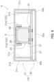
FIG. 3 is a cross-sectional view schematically showing a cross section of the control unit which is cut along cutting line III inFIGS. 1 and2 . -
FIG. 4 is a cross-sectional view schematically showing a cross section of the control unit which is cut along cutting line III inFIGS. 1 and2 according to the other embodiment. - An electric vehicle according to an embodiment will be described below with reference to the drawings. In this embodiment, as shown in
FIG. 1 , an example, in which the electric vehicle is a straddled vehicle 1, is shown. A vehicle, which is different from the straddled vehicle 1, can be used as long as the vehicle is an electric vehicle. - A straddled vehicle 1 includes a vehicle body frame 2 (an example of a vehicle body), a
steering device 3, afront wheel 5, and a rear wheel 6. The straddled vehicle 1 further includes an electric motor 7 (an example of a controlled portion), acontrol unit 8, and a heat dissipation sheet 9 (seeFIG. 3 ). - As shown in
FIG. 2 , the straddled vehicle 1 includes a vehicle center plane H extending in a front-rear direction. In this embodiment, a front side of a rider (a left side inFIG. 1 ), a rear side of the rider (a right side inFIG. 1 ), a left side of the rider (a right side inFIG. 2 ), and a right side of the rider (a left side inFIG. 2 ) respectively correspond to front, rear, left and right directions of the straddled vehicle 1, in a state where the rider is seated on aseat 10. A vehicle width direction W is defined as a direction perpendicular to the vehicle center plane H. For example, the vehicle width direction W indicates the left-right direction with respect to the vehicle center plane H. - An upper side of the rider (an upper side in
FIGS. 1 and2 ) corresponds to an upper direction of the straddled vehicle 1. A lower direction of the straddled vehicle 1 (a lower direction inFIGS. 1 and2 ) is a direction opposite to the upper direction of the straddled vehicle 1. A side view of the straddled vehicle 1 shows a side view of the straddled vehicle 1 viewed from the left side or the right side. For example,FIG. 1 shows the side view of the straddled vehicle 1 viewed from the left side.FIG. 2 shows the front view of the straddled vehicle 1 viewed from the front side. - As shown in
FIGS. 1 and2 , the vehicle body frame 2 includes ahead pipe 11 and amain frame 12. Themain frame 12 is connected to thehead pipe 11. The vehicle body frame 2 includes the vehicle center plane H (seeFIG. 2 ) that passes through thehead pipe 11 in the front-rear direction. - As shown in
FIGS. 1 and2 , thesteering device 3 includes afront fork 15, a steeringshaft 16 and ahandle member 17. Thefront fork 15 is rotatably supported with respect to thehead pipe 11. The steeringshaft 16 is connected to thefront fork 15. Thehandle member 17 is connected to the steeringshaft 16. - As shown in
FIG. 1 , thefront wheel 5 is rotatably supported byfront fork 15. The rear wheel 6 is rotatably supported by the vehicle body frame 2, for example, themain frame 12. The rear wheel 6 are rotated by driving force of the electric motor 7. - As shown in
FIGS. 1 and2 , the electric motor 7 is provided on the vehicle body frame 2. For example, the electric motor 7 is mounted to a lower portion of themain frame 12. The electric motor 7 is driven by a battery 4 shown inFIG. 1 . The driving force of the electric motor 7 is transmitted to the rear wheel 6. For example, the electric motor 7 drives the rear wheel 6 via the chain C. - The
control unit 8 is electrically connected to the electric motor 7 and controls the electric motor 7. As shown inFIG. 1 , thecontrol unit 8 is mounted to the vehicle body frame 2. As shown inFIG. 3 , thecontrol unit 8 includes acase member 20, acontrol board 21,electronic component 22, and a supportingstructure 23. - The
case member 20 is mounted to the vehicle body frame 2. For example, as shown inFIG. 1 , thecase member 20 is mounted to themain frame 12 on the rear side than thefront fork 15. As shown inFIG. 2 , thecase member 20 is disposed in the vehicle width direction W on the rear side than thefront fork 15. - As shown in
FIG. 3 , thecase member 20 forms an internal space S. The internal space S is used as a heat dissipation space for theelectronic component 22 and a filler such as resin isn't disposed in the internal space S. - As shown in
FIG. 3 , thecase member 20 includes afirst case 25 and asecond case 26. Thecontrol board 21 is mounted to thefirst case 25. Thefirst case 25 includes a firstbottom wall 25a, a first supportingwall 25b, and afirst side wall 25c. The firstbottom wall 25a is disposed so as to face thesecond case 26, for example, a secondbottom wall 26a of thesecond case 26. The secondbottom wall 26a will be described later. An inner surface of the firstbottom wall 25a forms the internal space S of thecase member 20. - The first supporting
wall 25b supports thecontrol board 21. The first supportingwall 25b is integrally formed with the firstbottom wall 25a. The first supportingwall 25b can be formed in any way as long as the first supportingwall 25b can support thecontrol board 21. - For example, the first supporting
wall 25b protrudes from the inner surface of the firstbottom wall 25a. Specifically, the first supportingwall 25b protrudes from the inner surface of the firstbottom wall 25a toward thesecond case 26, for example, the secondbottom wall 26a of thesecond case 26. - The
first side wall 25c is integrally formed with the firstbottom wall 25a so as to surround an outer edge of the firstbottom wall 25a. Thefirst side wall 25c extends toward thesecond case 26, for example, thesecond side wall 26c of thesecond case 26. An inner surface of thefirst side wall 25c forms the internal space S of thecase member 20. - As shown in
FIG. 3 , thesecond case 26 covers thecontrol board 21 and theelectronic component 22. Thefirst case 25 is mounted to thesecond case 26. For example, thesecond case 26 includes a secondbottom wall 26a (an example of a first wall portion), a second supportingwall 26b (an example of a second wall portion), and asecond side wall 26c. - The second
bottom wall 26a is disposed so as to face thefirst case 25, for example, the firstbottom wall 25a of thefirst case 25. For example, the secondbottom wall 26a is disposed so as to face thecontrol board 21. An inner surface of the secondbottom wall 26a forms the internal space S of thecase member 20. - The second supporting
wall 26b is formed on the secondbottom wall 26a. For example, the second supportingwall 26b protrudes from the inner surface of the secondbottom wall 26a. Specifically, the second supportingwall 26b protrudes from the inner surface of the secondbottom wall 26a toward thefirst case 25, for example, the firstbottom wall 25a of thefirst case 25. More specifically, the second supportingwall 26b protrudes from the inner surface of the secondbottom wall 26a toward thecontrol board 21. The second supportingwall 26b configures the supportingstructure 23 which will be described later. - The
second side wall 26c is integrally formed with the secondbottom wall 26a so as to surround an outer edge of the secondbottom wall 26a. Thesecond side wall 26c extends toward thefirst case 25, for example, thesecond side wall 26c of thefirst case 25. The inner surface of thesecond side wall 26c forms the internal space S of thecase member 20. - The
first case 25 and thesecond case 26 are fixed to each other in a state where a tip of thefirst side wall 25c contacts with a tip of thesecond side wall 26c. For example, the tip of thefirst side wall 25c and the tip of thesecond side wall 26c are preferably fixed to each other by a fixing means such as an adhesive. In this state, the internal space S is formed between thefirst case 25 and thesecond case 26. Thecontrol board 21 and theelectronic component 22 are disposed in the internal space S. - The
control board 21 controls theelectronic component 22. As shown inFIG. 3 , thecontrol board 21 is mounted to thecase member 20 in the internal space S of thecase member 20. For example, thecontrol board 21 is mounted to thefirst case 25. Specifically, thecontrol board 21 is mounted to the first supportingwall 25b. - As shown in
FIG. 3 , theelectronic component 22 is mounted to thecontrol board 21 in the internal space S of thecase member 20. For example, theelectronic component 22 is fixed to thecontrol board 21 by a fixing means such as a solder. In this state, a side surface of a base end side of theelectronic component 22 and an outer surface of thecontrol board 21 are further fixed by the fixing means such as an adhesive 27. - As shown in
FIG. 3 , supportingstructure 23 supports theelectronic component 22. For example, the supportingstructure 23 supports theelectronic component 22 so that theelectronic component 22 is partially exposed in the internal space S of thecase member 20. The supportingstructure 23 is provided on the inner surface of thecase member 20. For example, the supportingstructure 23 is provided on the inner surface of thesecond case 26member 20. Specifically, the supportingstructure 23 is configured by the second supportingwall 26b of thesecond case 26. - The second supporting
wall 26b supports theelectronic component 22. The second supportingwall 26b is integrally formed with the secondbottom wall 26a so as to surround a tip portion of theelectronic component 22. For example, the second supportingwall 26b is integrally formed with the secondbottom wall 26a so as to surround a side surface of the tip portion of theelectronic component 22. - The side surface of the tip portion of the
electronic component 22 is fixed to the second supportingwall 26b via a fixing means such as an adhesive 28. In this state, a tip 26b1 of the second supportingwall 26b is disposed at an interval from thecontrol board 21. The heat of theelectronic component 22 is dissipated in the internal space S by a distance D between the tip 26b1 of the second supportingwall 26b and thecontrol board 21. - As shown in
FIG. 3 , theheat dissipation sheet 9 is disposed between thecase member 20 and theelectronic component 22. For example, theheat dissipation sheet 9 is disposed between the secondbottom wall 26a of thesecond case 26 and atip surface 22a of theelectronic component 22. Specifically, theheat dissipation sheet 9 is disposed between the inner surface of the secondbottom wall 26a which is provided inside the second supportingwall 26b and thetip surface 22a of theelectronic component 22. - With the straddled vehicle 1 including the above configuration, the
control unit 8 is assembled as follows. First, theheat dissipation sheet 9 is mounted to thetip surface 22a of theelectronic component 22. Theelectronic component 22 is mounted to thecontrol board 21. The side surface of the base end side of theelectronic component 22 and the outer surface of thecontrol board 21 are fixed by the adhesive 27. In this state, thecontrol board 21 is mounted to thefirst case 25. - Next, the adhesive 28 is applied to the inner surface of the second supporting
wall 26b of thesecond case 26. The tip portion of theelectronic component 22 is disposed in a space which is surrounded by the secondbottom wall 26a of thesecond case 26 and the second supportingwall 26b of thesecond case 26. Thereby, theheat dissipation sheet 9 is disposed between the inner surface of the secondbottom wall 26a and thetip surface 22a of theelectronic component 22. Finally, thefirst case 25 is fixed to thesecond case 26. - The straddled vehicle 1 described above has the following features. The straddled vehicle 1 can suitably dissipate the heat of the
electronic component 22, because theelectronic component 22 is partially exposed in the internal space S of thecase member 20. - With the straddled vehicle 1, the
electronic component 22 can be suitably positioned without using the filler such as resin, because theelectronic component 22 is supported by the second supportingwall 26b of the supportingstructure 23. - With the straddled vehicle 1, the
electronic component 22 can be
more suitably positioned, because the second supportingwall 26b of the supportingstructure 23 surrounds the side surface of the tip portion of theelectronic component 22. - With the straddled vehicle 1, the
electronic component 22 can be more suitably positioned, because the side surface of the tip portion of theelectronic component 22 is fixed to the second supportingwall 26b by the adhesive 28. - With the straddled vehicle 1, the heat of the
electronic component 22 can be more suitably dissipated, because the straddled vehicle 1 includes theheat dissipation sheet 9 which is disposed between thecase member 20 and theelectronic component 22. - With the straddled vehicle 1, the
control board 21 and theelectronic component 22 can be easily disposed in the internal space S between thefirst case 25 and thesecond case 26 by mounting thesecond case 26 to thefirst case 25 in a state where theelectronic component 22 is supported by the second supportingwall 26b of the supportingstructure 23. - The above embodiment can be configured as follows. As shown in
FIG. 4 , thecase member 120 includes a third case 30 (an example of a second case) and a fourth case 31 (an example of a first case). Thethird case 30 covers thecontrol board 21. For example, thethird case 30 covers thecontrol board 21 in a state where thecontrol board 21 is mounted to thefourth case 31. - In the other embodiments, the same reference numerals as the above embodiment is used for the same configurations as the above embodiment. The explanation of the configurations indicated by the same reference numerals is omitted in the other embodiment. The configuration omitted here conforms to the configuration of the above embodiment.
- As shown in
FIG. 4 , thethird case 30 includes a thirdbottom wall 30a corresponding to the firstbottom wall 25a of thefirst case 25 in the above embodiment and athird side wall 30b corresponding to thefirst side wall 25c of thefirst case 25 in the above embodiment. Thethird case 30 does not include a supporting wall corresponding to the first supportingwall 25b of thefirst case 25 in the above embodiment. - As shown in
FIG. 4 , thecontrol board 21 is mounted to thefourth case 31. Thefourth case 31 is fixed to thethird case 30 in the same way as the above embodiment. For example, thefourth case 31 includes a fourthbottom wall 31a corresponding to the secondbottom wall 26a of thesecond case 26 in the above embodiment, a third supportingwall 31b corresponding to the second supportingwall 26b of thesecond case 26 in the above embodiment, and afourth side wall 31c corresponding to thesecond side wall 26c of thesecond case 26 in the above embodiment. Thefourth case 31 further includes a fourth supportingwall 31d. - As shown in
FIG. 4 , the third supportingwall 31b configures a supportingstructure 123 and supports the tip portion of theelectronic component 22. The fourth supportingwall 31d supports thecontrol board 21. The fourth supportingwall 31d is integrally formed with the fourthbottom wall 31a. The fourth supportingwall 31d can be formed in any way as long as the fourth supportingwall 31d can support thecontrol board 21. - For example, the fourth supporting
wall 31d protrudes from an inner surface of the fourthbottom wall 31a. Specifically, the fourth supportingwall 31d protrudes from the inner surface of the fourthbottom wall 31a toward thethird case 30, for example, the thirdbottom wall 30a of thethird case 30. - With the straddled vehicle 1 including the above configuration, the
control unit 8 is assembled as follows. First, theheat dissipation sheet 9 is mounted to thetip surface 22a of theelectronic component 22. Theelectronic component 22 are mounted to thecontrol board 21. The side surface of the base end side of theelectronic component 22 and the outer surface of thecontrol board 21 are fixed by the adhesive 27. - Next, the adhesive 28 is applied to the inner surface of the third supporting
wall 31b of thefourth case 31. In this state, the tip portion of theelectronic component 22 is disposed in a space which is surrounded by the fourthbottom wall 31a of thefourth case 31 and the third supportingwall 31b of thefourth case 31. Also, thecontrol board 21 is fixed to the fourth supportingwall 31d. Thereby, theheat dissipation sheet 9 is disposed between the inner surface of the fourthbottom wall 31a and thetip surface 22a of theelectronic component 22. Finally, thethird case 30 is fixed to thefourth case 31 so as to cover thecontrol board 21. - In this case, the
control board 21 andelectronic component 22 are mounted to thefourth case 31. By fixing thethird case 30 to thefourth case 31 in this state, thecontrol board 21 and theelectronic component 22 can be easily disposed in the internal space S between thethird case 30 and thefourth case 31. Also, in this case, it is possible to obtain the same effects as the above embodiment. - The present teaching can be applied to an electric vehicles.
-
- 1 a straddled vehicle
- 2 a vehicle body frame
- 7 an electric motor
- 8 an control unit
- 9 a heat dissipation sheet
- 20, 120 a case member
- 21 a control board
- 22 an electronic component
- 23,123 supporting structure
- 25 a first case
- 26 a second case
- 26a a second bottom wall
- 26b a second supporting wall
- 30 a third case
- 31 a fourth case
- 31a a fourth bottom wall
- 31b a third supporting wall
- S an internal space
Claims (12)
- An electric vehicle (1) comprising:a vehicle body (2);a controlled portion (7) mounted to the vehicle body (2) and configured to be electrically controlled; anda control unit (8) configured to control the controlled portion (7) and including a case member (20, 120) mounted to the vehicle body (2) and forming an internal space (S),a control board (21) mounted to the case member (20, 120) in the internal space (S),an electronic component (22) mounted to the control board (21) in the internal space (S) and a supporting structure (23, 123) provided on an inner surface of the case member (20, 120) and configured to support the electronic component (22) so that the electronic component (22) is partially exposed in the internal space (S).
- The electric vehicle (1) according to claim 1, wherein the case member (20) includesa first wall portion (26a, 31a) and a second wall portion (26b, 31b),the first wall portion (26a, 31a) includes the inner surface which is disposed so as to face the control board (21), andthe second wall portion (26b, 31b) protrudes from the first wall portion (26a, 31a) toward the control board (21) and configures the supporting structure (23, 123).
- The electric vehicle (1) according to claim 2, wherein the second wall portion (26b, 31b) is formed on the first wall portion (26a, 31a) so as to surround a side surface of the electronic component (22).
- The electric vehicle (1) according to claim 2 or 3, wherein the side surface of the electronic component (22) is fixed to the second wall portion (26b, 31b) by an adhesive (28).
- The electric vehicle (1) according to any of the claim 1 to 4, further comprising:
a heat dissipation sheet (9) disposed between the case member (20, 120) and the electronic component (22). - The electric vehicle (1) according to any of the claim 1 to 5, wherein the case member (20) includes a first case (25) to which the control board (21) is mounted and a second case (26) mounted to the first case (25),the second case (26) is configured to cover the control board (21) and the electronic component (22), andthe supporting structure (23) is provided on the second case (26).
- The electric vehicle (1) according to any of the claim 1 to 5, wherein the case member (120) includes a first case (31) to which the control board (21) is mounted and a second case (30) mounted to the first case (31),the second case (30) is configured to cover the control board (21),the electronic component (22) is disposed between the control board (21) and the first case (31); andthe supporting structure (23,123) is provided on the first case (31).
- The electric vehicle (1) according to claim 6 or 7, wherein first case (25, 31) includes at least one supporting wall (25b, 31d) that supports the control board (21).
- The electric vehicle (1) according to any of the claim 1 to 8, wherein controlled portion is an electric motor (7).
- The electric vehicle (1) according to any of the claim 1 to 9, wherein the electric vehicle is a straddled vehicle.
- The electric vehicle (1) according to any of the claim 1 to 10, wherein the vehicle body is a vehicle body frame (2).
- The electric vehicle (1) according to any of the claim 1 to 11, wherein a side surface of the electronic component (22) is fixed to the control board (21) by an adhesive (27).
Applications Claiming Priority (1)
| Application Number | Priority Date | Filing Date | Title |
|---|---|---|---|
| JP2022142293A JP2024037427A (en) | 2022-09-07 | 2022-09-07 | electric vehicle |
Publications (1)
| Publication Number | Publication Date |
|---|---|
| EP4336981A1 true EP4336981A1 (en) | 2024-03-13 |
Family
ID=86497729
Family Applications (1)
| Application Number | Title | Priority Date | Filing Date |
|---|---|---|---|
| EP23174788.2A Pending EP4336981A1 (en) | 2022-09-07 | 2023-05-23 | Electric vehicle |
Country Status (3)
| Country | Link |
|---|---|
| US (1) | US20240081030A1 (en) |
| EP (1) | EP4336981A1 (en) |
| JP (1) | JP2024037427A (en) |
Citations (7)
| Publication number | Priority date | Publication date | Assignee | Title |
|---|---|---|---|---|
| EP1508915A2 (en) * | 2003-08-18 | 2005-02-23 | Delphi Technologies, Inc. | Process and electronic assembly for removing heat from a circuit device |
| JP2005129820A (en) | 2003-10-27 | 2005-05-19 | Mitsubishi Electric Corp | Electronic circuit equipment |
| JP2011198985A (en) * | 2010-03-19 | 2011-10-06 | Hitachi Automotive Systems Ltd | Electronic control device for vehicle |
| JP2012227472A (en) * | 2011-04-22 | 2012-11-15 | Mitsubishi Electric Corp | Electronic component mounting structure |
| US20170295662A1 (en) * | 2014-10-09 | 2017-10-12 | Denso Corporation | Electrical device, method for manufacturing electrical device, and electric compressor |
| US20180228047A1 (en) * | 2015-08-03 | 2018-08-09 | Autonetworks Technologies, Ltd. | Electrical junction box |
| US20210175145A1 (en) * | 2017-12-11 | 2021-06-10 | Hitachi Automotive Systems, Ltd. | Electronic control device |
Family Cites Families (6)
| Publication number | Priority date | Publication date | Assignee | Title |
|---|---|---|---|---|
| JP4611820B2 (en) * | 2005-07-04 | 2011-01-12 | 本田技研工業株式会社 | Cooling device for electric unit for vehicle |
| DE102011012673A1 (en) * | 2010-03-17 | 2011-09-22 | Hitachi Automotive Systems, Ltd. | Electronic control device for vehicles |
| JP5352573B2 (en) * | 2010-12-22 | 2013-11-27 | 本田技研工業株式会社 | Electric vehicle |
| WO2012090241A1 (en) * | 2010-12-27 | 2012-07-05 | 川崎重工業株式会社 | Saddle-type electric vehicle |
| WO2013061386A1 (en) * | 2011-10-28 | 2013-05-02 | 川崎重工業株式会社 | Straddle-type electric vehicle |
| US12245408B2 (en) * | 2020-03-20 | 2025-03-04 | Lyft, Inc. | Motor controller heat dissipating systems and methods |
-
2022
- 2022-09-07 JP JP2022142293A patent/JP2024037427A/en active Pending
-
2023
- 2023-05-23 EP EP23174788.2A patent/EP4336981A1/en active Pending
- 2023-06-21 US US18/338,868 patent/US20240081030A1/en active Pending
Patent Citations (7)
| Publication number | Priority date | Publication date | Assignee | Title |
|---|---|---|---|---|
| EP1508915A2 (en) * | 2003-08-18 | 2005-02-23 | Delphi Technologies, Inc. | Process and electronic assembly for removing heat from a circuit device |
| JP2005129820A (en) | 2003-10-27 | 2005-05-19 | Mitsubishi Electric Corp | Electronic circuit equipment |
| JP2011198985A (en) * | 2010-03-19 | 2011-10-06 | Hitachi Automotive Systems Ltd | Electronic control device for vehicle |
| JP2012227472A (en) * | 2011-04-22 | 2012-11-15 | Mitsubishi Electric Corp | Electronic component mounting structure |
| US20170295662A1 (en) * | 2014-10-09 | 2017-10-12 | Denso Corporation | Electrical device, method for manufacturing electrical device, and electric compressor |
| US20180228047A1 (en) * | 2015-08-03 | 2018-08-09 | Autonetworks Technologies, Ltd. | Electrical junction box |
| US20210175145A1 (en) * | 2017-12-11 | 2021-06-10 | Hitachi Automotive Systems, Ltd. | Electronic control device |
Also Published As
| Publication number | Publication date |
|---|---|
| US20240081030A1 (en) | 2024-03-07 |
| JP2024037427A (en) | 2024-03-19 |
Similar Documents
| Publication | Publication Date | Title |
|---|---|---|
| EP1862346B1 (en) | Vehicle Instrument Panel Device | |
| EP3109131B1 (en) | Steering wheel | |
| CN102530155A (en) | Vehicle handlebar support structure | |
| WO2014162738A1 (en) | Motor control device and production method therefor | |
| JP2017043340A (en) | Mounting structure of battery device and electric bicycle | |
| JP2019099047A (en) | Sensor mounting structure | |
| CN112441125A (en) | Vehicle body front structure | |
| JP2019099048A (en) | Sensor mounting structure | |
| JP6930472B2 (en) | Steering wheel | |
| US20240081030A1 (en) | Electric vehicle | |
| JP2016192888A (en) | Electronic control unit | |
| JP4983388B2 (en) | Vehicle seat | |
| EP2915729B1 (en) | Straddle-type vehicle | |
| JP7319270B2 (en) | Mobile radio equipment, drive units, mobiles and mobile communication systems | |
| CN110316300B (en) | Side cover structure of straddle-type vehicle | |
| JP2012206631A (en) | Vehicle-mounted control device | |
| JP2005126030A (en) | Mounting structure of membrane switch for automobile | |
| JP2016190630A (en) | Electronic control unit | |
| JP4805869B2 (en) | Working vehicle | |
| JP2005068743A (en) | Small snow blower | |
| EP4410644B1 (en) | Cowling structure | |
| JP2018052290A (en) | Head-up display device mounting structure | |
| EP4488154A1 (en) | Vehicle front structure | |
| EP4410645A1 (en) | Cowling structure | |
| JP4466317B2 (en) | Mounting structure of equipment to vehicle instrument panel |
Legal Events
| Date | Code | Title | Description |
|---|---|---|---|
| PUAI | Public reference made under article 153(3) epc to a published international application that has entered the european phase |
Free format text: ORIGINAL CODE: 0009012 |
|
| STAA | Information on the status of an ep patent application or granted ep patent |
Free format text: STATUS: REQUEST FOR EXAMINATION WAS MADE |
|
| 17P | Request for examination filed |
Effective date: 20230523 |
|
| AK | Designated contracting states |
Kind code of ref document: A1 Designated state(s): AL AT BE BG CH CY CZ DE DK EE ES FI FR GB GR HR HU IE IS IT LI LT LU LV MC ME MK MT NL NO PL PT RO RS SE SI SK SM TR |
|
| STAA | Information on the status of an ep patent application or granted ep patent |
Free format text: STATUS: EXAMINATION IS IN PROGRESS |
|
| P01 | Opt-out of the competence of the unified patent court (upc) registered |
Free format text: CASE NUMBER: APP_37600/2024 Effective date: 20240624 |
|
| 17Q | First examination report despatched |
Effective date: 20240710 |
|
| GRAP | Despatch of communication of intention to grant a patent |
Free format text: ORIGINAL CODE: EPIDOSNIGR1 |
|
| STAA | Information on the status of an ep patent application or granted ep patent |
Free format text: STATUS: GRANT OF PATENT IS INTENDED |