EP4336906A1 - Verfahren, vorrichtung und system zum senden von nachrichten - Google Patents
Verfahren, vorrichtung und system zum senden von nachrichten Download PDFInfo
- Publication number
- EP4336906A1 EP4336906A1 EP21939656.1A EP21939656A EP4336906A1 EP 4336906 A1 EP4336906 A1 EP 4336906A1 EP 21939656 A EP21939656 A EP 21939656A EP 4336906 A1 EP4336906 A1 EP 4336906A1
- Authority
- EP
- European Patent Office
- Prior art keywords
- node
- iab
- rrc reconfiguration
- message
- reconfiguration message
- Prior art date
- Legal status (The legal status is an assumption and is not a legal conclusion. Google has not performed a legal analysis and makes no representation as to the accuracy of the status listed.)
- Pending
Links
Images


Classifications
-
- H—ELECTRICITY
- H04—ELECTRIC COMMUNICATION TECHNIQUE
- H04W—WIRELESS COMMUNICATION NETWORKS
- H04W36/00—Hand-off or reselection arrangements
- H04W36/0005—Control or signalling for completing the hand-off
- H04W36/0009—Control or signalling for completing the hand-off for a plurality of users or terminals, e.g. group communication or moving wireless networks
-
- H—ELECTRICITY
- H04—ELECTRIC COMMUNICATION TECHNIQUE
- H04W—WIRELESS COMMUNICATION NETWORKS
- H04W76/00—Connection management
- H04W76/20—Manipulation of established connections
- H04W76/27—Transitions between radio resource control [RRC] states
-
- H—ELECTRICITY
- H04—ELECTRIC COMMUNICATION TECHNIQUE
- H04W—WIRELESS COMMUNICATION NETWORKS
- H04W28/00—Network traffic management; Network resource management
- H04W28/02—Traffic management, e.g. flow control or congestion control
- H04W28/08—Load balancing or load distribution
- H04W28/0867—Load balancing or load distribution among entities in the downlink
-
- H—ELECTRICITY
- H04—ELECTRIC COMMUNICATION TECHNIQUE
- H04W—WIRELESS COMMUNICATION NETWORKS
- H04W40/00—Communication routing or communication path finding
- H04W40/34—Modification of an existing route
- H04W40/36—Modification of an existing route due to handover
-
- H—ELECTRICITY
- H04—ELECTRIC COMMUNICATION TECHNIQUE
- H04W—WIRELESS COMMUNICATION NETWORKS
- H04W40/00—Communication routing or communication path finding
- H04W40/24—Connectivity information management, e.g. connectivity discovery or connectivity update
- H04W40/248—Connectivity information update
-
- H—ELECTRICITY
- H04—ELECTRIC COMMUNICATION TECHNIQUE
- H04W—WIRELESS COMMUNICATION NETWORKS
- H04W74/00—Wireless channel access
- H04W74/08—Non-scheduled access, e.g. ALOHA
- H04W74/0833—Random access procedures, e.g. with 4-step access
-
- H—ELECTRICITY
- H04—ELECTRIC COMMUNICATION TECHNIQUE
- H04W—WIRELESS COMMUNICATION NETWORKS
- H04W84/00—Network topologies
- H04W84/02—Hierarchically pre-organised networks, e.g. paging networks, cellular networks, WLAN [Wireless Local Area Network] or WLL [Wireless Local Loop]
- H04W84/04—Large scale networks; Deep hierarchical networks
- H04W84/042—Public Land Mobile systems, e.g. cellular systems
- H04W84/047—Public Land Mobile systems, e.g. cellular systems using dedicated repeater stations
-
- H—ELECTRICITY
- H04—ELECTRIC COMMUNICATION TECHNIQUE
- H04W—WIRELESS COMMUNICATION NETWORKS
- H04W88/00—Devices specially adapted for wireless communication networks, e.g. terminals, base stations or access point devices
- H04W88/08—Access point devices
- H04W88/085—Access point devices with remote components
-
- Y—GENERAL TAGGING OF NEW TECHNOLOGICAL DEVELOPMENTS; GENERAL TAGGING OF CROSS-SECTIONAL TECHNOLOGIES SPANNING OVER SEVERAL SECTIONS OF THE IPC; TECHNICAL SUBJECTS COVERED BY FORMER USPC CROSS-REFERENCE ART COLLECTIONS [XRACs] AND DIGESTS
- Y02—TECHNOLOGIES OR APPLICATIONS FOR MITIGATION OR ADAPTATION AGAINST CLIMATE CHANGE
- Y02D—CLIMATE CHANGE MITIGATION TECHNOLOGIES IN INFORMATION AND COMMUNICATION TECHNOLOGIES [ICT], I.E. INFORMATION AND COMMUNICATION TECHNOLOGIES AIMING AT THE REDUCTION OF THEIR OWN ENERGY USE
- Y02D30/00—Reducing energy consumption in communication networks
- Y02D30/70—Reducing energy consumption in communication networks in wireless communication networks
Definitions
- This disclosure relates to the field of communication technologies.
- the ultra-dense network is one of goals of 5G, and deployment of an NR network with no wired backhaul is very important for the realization of 5G ultra-dense network.
- a wireless self-backhauling system is of multi-hop to meet deployment requirements.
- High bandwidth, large-scale MIMO and beam system of 5G make it easier for 5G to develop the wireless self-backhauling system of ultra-dense NR cells than LTE.
- IAB integrated access and backhaul
- FIG. 1 is a schematic diagram of an IAB system.
- a relay node supports access and backhaul functions at the same time.
- a wireless transmission link of the relay node multiplexes an access link and backhaul link in the time domain, frequency domain or spatial domain.
- the access link and backhaul link may use identical or different frequency bands.
- the relay node refers to an IAB-node, which supports access and backhaul functions at the same time.
- a last hop of access node at the network side is referred to as an IAB-donor, which supports a gNB function and supports IAB-node access. All UE data may be backhauled to the IAB-donor in one or more hops via the IAB-node.
- IAB-node Functions of the IAB-node are divided into two parts, one is a gNB-DU function, referred to as an IAB-DU (distribution unit), and the other is a UE function, referred to as an IAB-MT (mobile terminal).
- the IAB-DU realizes function at a network side device, is connected to a downstream child IAB-node, provides NR air access to the UE and the downstream child IAB-node, and establishes F 1 connection with the IAB donor-CU.
- the IAB-MT realizes some functions of a terminal equipment and is connected to an upstream parent IAB-node or IAB-donor DU.
- the IAB-MT includes physical layer, layer 2, RRC and NAS layer functions, and is further indirectly connected to the IAB donor-CU and a core network (CN).
- CN core network
- the IAB-node may access to the network in a standalone (SA) mode or non-standalone (EN-DC, E-UTRA-NRDualConnectivity) mode.
- FIG. 2 is a schematic diagram of an IAB architecture of the SA mode.
- FIG. 3 is a schematic diagram of an IAB architecture of the EN-DC mode.
- FIG. 4 is a schematic diagram of an IAB-node, a parent IAB-node and a child IAB-node. As shown in FIG. 4 , an IAB-DU of the IAB-node is taken as a network side to connect to IAB-MT of the child IAB-node, and an IAB-MT of the IAB-node is taken as a terminal side to connect to IAB-DU of the parent IAB-node.
- FIG. 5 is a schematic diagram of an F 1 user interface (F 1-U) protocol stack between the IAB-DU and IAB-donor CU.
- FIG. 6 is a schematic diagram of an F1 control plane (F1-C) protocol stack between the IAB-DU and IAB-donor CU.
- the F1-U and F1-C are built on a transmission (IP) layer between the IAB-DU and IAB-donor-CU. Two hops of wireless backhaul and one hop of wired backhaul are performed in FIG. 5 and FIG. 6 .
- the transmission (IP) layer is carried on a backhaul adaptive protocol (BAP) sublayer.
- BAP backhaul adaptive protocol
- BAP PDUs are transmitted in an RLC channel of the backhaul link
- multiple RLC channels of the backhaul link may be configured by the IAB-donor to carry services of different priorities and QoS
- the BAP entity maps the BAP PDUs to different backhaul RLC channels.
- an IAB system has supported adaptive changes in topology and routing caused by movement of the IAB-node between different DUs under the same donor-CU.
- the IAB-node moves under the same donor-CU (at this moment, the IAB-node is referred to as a migrating IAB-node)
- a topology relation with a downstream IAB-node and a UE is still maintained.
- changes in transmission paths from the IAB-node and its child node to a donor-CU i.e. changes in a network topology, such as changes in a network topology resulted when the IAB-node is handed over to the new parent node or establishes dual connection to the new parent node.
- FIG. 7 is a schematic diagram of the changes in the network topology resulted from the movement of the IAB-node.
- IAB-node 5 is handed over from a cell under IAB-node 3 to a cell under IAB-node 4
- transmission paths from IAB-node 5 and its downstream child node IAB-node 6 to the donor-CU are changed from passing IAB-node 1 and IAB-node 2 to passing IAB-node 2 and IAB-node 4, i.e. the network topology is changed.
- the donor-CU may configure configuration information related to network topology adaptation for the IAB-node via an RRC reconfiguration message, wherein the default routing identifier includes a BAP address and path ID of a destination donor-DU.
- the IAB-node After the IAB-node is handed over to a new parent node, the IAB-node begins to apply the above configuration information.
- configurations related to the network topology adaptation may be performed in the same method.
- an IAB-node handed over to a new parent node and its child node are unable to be made to simultaneously perform F1 path migration, which may result in a longer service interruption timing during a process of path migration of the IAB-node.
- network topology adaptation of a child node is performed after access of the IAB-node to a new parent node, and the child node performs network topology adaptation after the IAB-node.
- a donor-DU parent node
- an address of an original donor-DU is carried by uplink data generated by the child node according to the original path configuration, which is different from an address of a new donor-DU.
- uplink data is dropped by the new donor-DU, thereby resulting in the uplink data generated by the child node according to the original path configuration to be unable to be transmitted to a CU, and the dropped uplink data is retransmitted by the UE, thereby resulting in longer data transmission latency and service interruption timing.
- the donor-DU needs to transmit configuration messages related to network topology adaptation to the IAB-node and each downstream child node thereof.
- a configuration message for each node need to be transmitted separately, thereby resulting in large amount of overhead of signaling messages, and also leading to longer service interruption timing.
- embodiments of this disclosure provide a message transmission method and apparatus and a system.
- a message transmission apparatus applicable to a first integrated access and backhaul node (IAB-node), the apparatus including:
- a message transmission apparatus applicable to a second integrated access and backhaul node (IAB-node), the apparatus including:
- a message transmission apparatus applicable to a second integrated access and backhaul node (IAB-node), the apparatus including:
- An advantage of the embodiments of this disclosure exists in that before the IAB-node is handed over to a new parent node, information related to network topology adaptation configured for its child node is transmitted by the donor-DU to the IAB-node and buffered in the IAB-node.
- the IAB-node forwards the information related to network topology adaptation configured by the donor-DU for its child node to its child node.
- the IAB-node and its child node may be made to almost simultaneously perform network topology adaptation, thereby reducing service interruption timing resulted from node migration.
- terms “first”, and “second”, etc. are used to differentiate different elements with respect to names, and do not indicate spatial arrangement or temporal orders of these elements, and these elements should not be limited by these terms.
- Terms “and/or” include any one and all combinations of one or more relevantly listed terms.
- Terms “contain”, “include” and “have” refer to existence of stated features, elements, components, or assemblies, but do not exclude existence or addition of one or more other features, elements, components, or assemblies.
- single forms “a”, and “the”, etc. include plural forms, and should be understood as “a kind of” or “a type of” in a broad sense, but should not defined as a meaning of "one”; and the term “the” should be understood as including both a single form and a plural form, except specified otherwise.
- the term “according to” should be understood as “at least partially according to”, the term “based on” should be understood as “at least partially based on”, except specified otherwise.
- the term “communication network” or “wireless communication network” may refer to a network satisfying any one of the following communication standards: long term evolution (LTE), long term evolution-advanced (LTE-A), wideband code division multiple access (WCDMA), and highspeed packet access (HSPA), etc.
- LTE long term evolution
- LTE-A long term evolution-advanced
- WCDMA wideband code division multiple access
- HSPA highspeed packet access
- communication between devices in a communication system may be performed according to communication protocols at any stage, which may, for example, include but not limited to the following communication protocols: 1G (generation), 2G, 2.5G, 2.75G, 3G, 4G, 4.5G, and 5G and 6G in the future, etc., and/or other communication protocols that are currently known or will be developed in the future.
- the term "network device”, for example, refers to a device in a communication system that accesses a user equipment to the communication network and provides services for the user equipment.
- the network device may include but not limited to the following equipment: a base station (BS), an access point (AP), a transmission reception point (TRP), a broadcast transmitter, a mobile management entity (MME), a gateway, a server, a radio network controller (RNC), a base station controller (BSC), etc.
- the base station may include but not limited to a node B (NodeB or NB), an evolved node B (eNodeB or eNB), and a 5G base station (gNB), etc. Furthermore, it may include a remote radio head (RRH), a remote radio unit (RRU), a relay, or a low-power node (such as a femto, and a pico, etc.).
- NodeB or NB node B
- eNodeB or eNB evolved node B
- gNB 5G base station
- RRH remote radio head
- RRU remote radio unit
- relay or a low-power node (such as a femto, and a pico, etc.).
- base station may include some or all of its functions, and each base station may provide communication coverage for a specific geographical area.
- a term “cell” may refer to a base station and/or its coverage area, depending on a context of the term.
- the term "user equipment (UE)” refers to, for example, an equipment accessing to a communication network and receiving network services via a network device, and may also be referred to as "a terminal equipment (TE)".
- the terminal equipment may be fixed or mobile, and may also be referred to as a mobile station (MS), a terminal, a subscriber station (SS), an access terminal (AT), or a station, etc.
- the terminal equipment may include but not limited to the following devices: a cellular phone, a personal digital assistant (PDA), a wireless modem, a wireless communication device, a hand-held device, a machine-type communication device, a lap-top, a cordless telephone, a smart cell phone, a smart watch, and a digital camera, etc.
- PDA personal digital assistant
- wireless modem a wireless communication device
- hand-held device a machine-type communication device
- a machine-type communication device a lap-top
- a cordless telephone a smart cell phone, a smart watch, and a digital camera, etc.
- the user equipment may also be a machine or a device performing monitoring or measurement.
- the user equipment may include but not limited to a machine-type communication (MTC) terminal, a vehicle mounted communication terminal, a device to device (D2D) terminal, and a machine to machine (M2M) terminal, etc.
- MTC machine-type communication
- D2D device to device
- M2M machine to machine
- IAB-node 3 is a parent node of IAB-node 4, and IAB-node 4 is a parent node of IAB-node 5.
- network topology is changed, that is, transmission paths between IAB-node 3, IAB-node 4, IAB-node 5 and the donor-CU are changed.
- the donor-CU transmits configuration messages related to network topology adaptation to IAB-node 3, IAB-node 4 and IAB-node 5, so that F1 transmission paths are handed over from original paths to new paths.
- the network topology adaptation for IAB-node 4 and IAB-node 5 is performed after access of IAB-node 3 to the new parent node is completed, that is, network topology adaptation of IAB-node 4 and IAB-node 5 are performed after IAB-node 3. Hence, it causes uplink data transmitted by IAB-node 4 and IAB-node 5 according to original configurations to be dropped by donor-DU 2, thereby resulting in longer transmission latency and service interruption timing.
- the donor-CU transmits a downlink F1AP (F1 application protocol) message carrying configuration information related to the network topology adaptation respectively for IAB-node 3 and each of its child node, i.e. transmitting DL F1AP MESSAGE to IAB-node 3 and respective parent nodes of its child node (see messages A, B and C in FIG. 7 ).
- F1AP F1 application protocol
- the information related to the network topology adaptation configured for its child node is transmitted by the donor-CU to the IAB-node and buffered in the IAB-node.
- the IAB-node forwards the information related to the network topology adaptation configured by the donor-CU to its child node.
- a first IAB-node is taken as a migration node (such as IAB-node 3 in FIG. 7 ) and is an IAB-node under control of a donor-CU.
- the first IAB-node is migrated (handed over) from a first parent node (such as IAB-node 1 in FIG. 7 ) to a second parent node (such as IAB-node 2 in FIG. 7 ).
- a second IAB-node (such as IAB-node 4 in FIG. 7 ) is a downstream child node of the first IAB-node, and a third IAB-node (such as IAB-node 5 in FIG.
- IAB-node 7 is a downstream child node of the second IAB-node.
- the number of the second IAB-node or third IAB-node may be one or at least two, and the third IAB-node may also have other child node, and the embodiments of this disclosure is not limited thereto.
- IAB-node 4 in FIG. 7 is taken as the second IAB-node
- IAB-node 5 is taken as the third IAB-node
- IAB-node 5 has no other child node as examples.
- the embodiments of this disclosure provide a message transmission method, which shall be described from a first IAB-node side.
- FIG. 8 is a schematic diagram of the message transmission method of this embodiment. As shown in FIG. 8 , the method includes:
- both the first RRC reconfiguration message and the second RRC reconfiguration message in 801 and 802 are configured and generated by the donor-CU.
- the first or second RRC reconfiguration message from the donor-CU may be directly transmitted by the donor-CU to the first IAB-node, or may be transmitted by the donor-CU to the first parent node and forwarded by the first parent node to the first IAB-node, and the embodiments of this disclosure is not limited thereto.
- the first IAB-node determines that the second RRC reconfiguration message is forwarded to the second IAB-node only when the first RRC reconfiguration message is used for path migration of the first IAB-node.
- the first RRC reconfiguration message contains a first parameter configured for the first IAB-node to change a transmission path
- the first IAB-node may determine that the first RRC reconfiguration message is used for path migration of the first IAB-node.
- the first parameter includes a default backhaul radio link control (BH RLC) channel, or a default backhaul adaptation protocol (BAP) route, or an Internet protocol (IP) address, configured for the first IAB-node.
- BH RLC backhaul radio link control
- BAP backhaul adaptation protocol
- IP Internet protocol
- the default BH RLC channel may be a BH RLC channel used by uplink F1-C and non-F1 data
- the default BAP route may be a route used by the uplink F1-C and non-F1 data, including a path identifier and a destination BAP address
- the IP address denotes an IP address routable to a new donor-DU (such as donor-DU 2 in FIG. 7 ) handed over to a second parent node.
- the first IAB-node receives the first RRC reconfiguration message containing the first parameter, it determines that the first RRC reconfiguration message is a configuration message for path migration.
- the first IAB-node determines that the first RRC reconfiguration message is a configuration message for path migration according to that the first RRC reconfiguration message includes first path migration indication information.
- the RRC message may possibly not be used for path migration, hence, it is needed to explicitly indicate RRC reconfiguration related to path migration to the first IAB-node, wherein the first path migration indication information is used to indicate that the first RRC reconfiguration message is a reconfiguration message used by the first IAB-node for performing path migration.
- this method is applicable to a case where the first IAB-node performs path migration between different donor-DUs (the donor-DUs are changed after handover to the new parent node), the first RRC reconfiguration message is used by the first IAB-node for path migration between the donor-DUs.
- the first path migration indication information is used to indicate that the first IAB-node is performing path migration between donor-DUs, that is, that the first RRC message contains the first path migration indication information indicates that the first RRC reconfiguration message is a reconfiguration message used by the first IAB-node for performing path migration between different donor-DUs.
- the first RRC reconfiguration message and the second RRC reconfiguration message may be carried by a downlink message, that is, the first IAB-node receives the first RRC reconfiguration message and the second RRC reconfiguration message at the same time, or the first RRC reconfiguration message and the second RRC reconfiguration message may be carried respectively by two downlink messages, that is, the first IAB-node receives the second RRC reconfiguration message and the first RRC reconfiguration message successively, which shall be explained later in detail.
- the first IAB-node is handed over to the second parent node and performs path migration, wherein the first IAB-node needs to perform random access so as to be handed over to the second parent node, and the first RRC reconfiguration message contains information related to that the first IAB-node is handed over to the second parent node.
- the first IAB-node triggers RRC reestablishment, and reference may be made to RRC reestablishment of an IAB-node in existing techniques for a process of RRC reestablishment, which shall not be repeated herein any further. Furthermore, the first IAB-node needs to transmit path migration failure indication information to its child node, and optionally, the second RRC reconfiguration message may also be forwarded to its child node or the second RRC reconfiguration message may also be cleared. Specific behaviors of its child node when the random access fails shall be explained later in the embodiments of a second aspect.
- the method may further include: the first IAB-node transmits a first RRC reconfiguration complete message to the donor-CU.
- the first IAB-node may also receive second RRC reconfiguration complete message transmitted by the second IAB-node.
- the second RRC reconfiguration complete message may be forwarded to the donor-CU, wherein the first RRC reconfiguration complete message and the second RRC reconfiguration complete message may be carried by one uplink message, or may be carried respectively by two or more uplink messages.
- the transmitting to the donor-CU may be transmitting to the donor-CU directly, or may be forwarding to the donor-CU via the second parent node, which shall be explained later in detail.
- the information related to network topology adaptation configured for its child node is transmitted by the donor-CU to the IAB-node and buffered in the IAB-node.
- the IAB-node forwards the information related to network topology adaptation configured by the donor-CU for its child node to its child node.
- the IAB-node and its child node may be made to almost simultaneously perform network topology adaptation, thereby reducing service interruption timing resulted from node migration.
- the embodiments of this disclosure provide a message transmission method, which shall be described from a second IAB-node side. Behaviors at a third IAB-node side are similar to those at the second IAB-node side, which shall not be enumerated herein any further.
- the second IAB-node receives a third RRC reconfiguration message for path migration of the third IAB-node from a donor-CU.
- the third RRC reconfiguration message is configured and generated by the donor-CU, and the third RRC reconfiguration message from the donor-CU may be directly transmitted by the donor-CU to the second IAB-node, or may be transmitted by the donor-CU to a first IAB-node and forwarded by the first IAB-node to the second IAB-node, or may be transmitted by the donor-CU to a first parent node and forwarded by the first parent node to the first IAB-node, and then forwarded by the first IAB-node to the second IAB-node; however, the embodiments of this disclosure is not limited thereto.
- the second IAB-node when the random access of the first IAB-node is successful (the random access is completed), the second IAB-node receives the second RRC reconfiguration message forwarded by the first IAB-node, and forwards the third RRC reconfiguration message to the third IAB-node when receiving the second RRC reconfiguration message; and when the random access of the first IAB-node fails (which may also be regarded as that the random access is not completed or is unable to be completed correctly), the second IAB-node receives the path migration failure indication information transmitted by the first IAB-node, and triggers an RRC reestablishment procedure or falls back to original path configuration, which shall be described below respectively.
- FIG. 9 is a schematic diagram of the message transmission method at the second IAB-node side when the random access of the first IAB-node is successful. As shown in FIG. 9 , the method includes:
- the method may further include (not shown in figures): the second IAB-node receives the second RRC reconfiguration message transmitted by the donor-CU and forwarded by the first IAB-node.
- the second RRC reconfiguration message is as described above, which shall not be repeated herein any further.
- the second RRC reconfiguration message and the third RRC reconfiguration message may be carried by one downlink message, or may be carried respectively by two downlink messages, which shall be described later in detail.
- the second IAB-node when receiving the second RRC reconfiguration message, performs path migration, and at the same time, triggers the second IAB-node to forward the buffered third RRC reconfiguration message to the third IAB-node.
- the second IAB-node does not change the parent node (the parent node is still the first IAB-node)
- the second RRC reconfiguration message does not contain handover information, and the second IAB-node does not need to perform a random access procedure.
- the second IAB-node forwards the third RRC reconfiguration message to the third IAB-node when it determines that the second RRC reconfiguration message is a configuration message for the path migration of the second IAB-node.
- the second RRC reconfiguration message may be determined to be used for the path migration of the second IAB-node in following two ways, for example, the second RRC reconfiguration message contains a second parameter for changing transmission path configuration for the second IAB-node, or the second RRC reconfiguration message contains second path migration indication information. Implementations of the second parameter and the second path migration indication information are identical to the implementations of the first parameter and the first path migration indication information, which shall not be repeated herein any further.
- the method may further include (not shown in figures): the second IAB-node transmits a second RRC reconfiguration complete message to the first IAB-node; and the second IAB-node receives the third RRC reconfiguration complete message transmitted by the third IAB-node.
- the third RRC reconfiguration complete message may also be forwarded to the donor-CU, wherein the second RRC reconfiguration complete message and the third RRC reconfiguration complete message may be carried by one uplink message, or may be carried respectively by two uplink messages.
- the transmitting to the donor-CU may be directly transmitting to the donor-CU, or may be forwarding to the donor-CU via the first IAB-node and/or the second parent node, which shall respectively be described later.
- the information related to network topology adaptation configured for its child node is transmitted by the donor-CU to the IAB-node and buffered in the IAB-node.
- the IAB-node forwards the information related to network topology adaptation configured by the donor-CU for its child node to its child node.
- the child node forwards information related to network topology adaptation configured by the donor-CU for its child node to its child node.
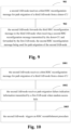
- FIG. 10 is a schematic diagram of the message transmission method at the second IAB-node side when the random access of the first IAB-node fails. As shown in FIG. 10 , the method includes:
- implementations of 1001 are as described above, which shall not be repeated herein any further.
- a T304 timer if a T304 timer expires, it indicates that the random access of the first IAB-node fails (which may also be regarded as that the random access is not completed or is unable to be completed or is unable to be completed correctly).
- the first IAB-node transmits path migration failure indication information to the second IAB-node, so that the second IAB-node performs the RRC reestablishment procedure.
- the first IAB-node may also forward the second RRC reconfiguration message to the second IAB-node or clear the second RRC reconfiguration message.
- the method may further include: the second IAB-node receives the second RRC reconfiguration message for path migration of the second IAB-node transmitted by the donor-CU to the first IAB-node and forwarded by the first IAB-node.
- the method may further include (not shown in figures): the second IAB-node forwards the path migration failure indication information received in 1002to the third IAB-node, so as to trigger the third IAB-node to perform RRC reestablishment.
- the method may further include (not shown in figures): the second IAB-node forwards the third RRC reconfiguration message to the third IAB-node, or clears the third RRC reconfiguration message.
- the second IAB-node forwards the third RRC reconfiguration message to the third IAB-node, or clears the third RRC reconfiguration message.
- the second IAB-node triggers the RRC reestablishment procedure, and reference may be made to RRC reestablishment of an IAB-node in existing techniques for the RRC reestablishment procedure, which shall not be repeated herein any further.
- the IAB-node and its child node may almost simultaneously perform RRC reestablishment, thereby reducing service interruption timing resulted from path migration failure.
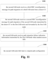
- FIG. 11 is another schematic diagram of the message transmission method at the second IAB-node side when the random access of the first IAB-node fails. As shown in FIG. 11 , the method includes:
- implementations of 1101 and 1103 are as described above, which shall not be repeated herein any further.
- the first IAB-node transmits the path migration failure indication information and the second RRC reconfiguration message to the second IAB-node, so that the second IAB-node falls back to the original path configuration.
- the second IAB-node does not perform RRC reestablishment, that is, although the second RRC reconfiguration message is received, the reconfiguration is not performed, and falling back to the original path configuration is only performed.
- the first IAB-node does not optionally forward the second RRC reconfiguration message to the second IAB-node, but it necessarily forwards the second RRC reconfiguration message, that is, 1102 is a necessary step; otherwise, a packet data aggregation protocol (PDCP) of the second IAB-node may be abnormal since the second RRC reconfiguration message is not received.
- PDCP packet data aggregation protocol
- the method may further include (not shown in figures): the second IAB-node forwards the third RRC reconfiguration message to the third IAB-node, and the second IAB-node forwards the path migration failure indication information received in 1103 to the third IAB-node, so that the third IAB-node falls back to the original path configuration.
- the first IAB-node side for a particular implementation, which shall not be repeated herein any further.
- the random access fails when the IAB-node hands over to the new parent node, it triggers RRC reestablishment, forwards the RRC reconfiguration of its child node to the child node and indicates path migration failure to the child node, so that the child node falls back to the original path configuration.
- the IAB-node fails in migration, the IAB-node and its child node may simultaneously fall back to the original path configuration; otherwise, if the child node performs path migration and generates uplink data according to the new path configuration, these uplink data is dropped and retransmitted by a UE, thereby resulting in an increase in uplink data transmission latency.
- This method may avoid prolonged data transmission time caused by path migration failure.
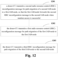
- the embodiments of this disclosure provide a message transmission method, which shall be described from a donor-CU side.
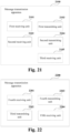
- FIG. 12 is a schematic diagram of the message transmission method. As shown in FIG. 12 , the method includes:
- the method may further include: 1203: the donor-CU transmits a third RRC reconfiguration message for path migration of the third IAB-node to the second IAB-node.
- the donor-CU generates the first RRC reconfiguration message, the second RRC reconfiguration message and the third RRC reconfiguration message, and reference may be made to embodiments of the first aspect and the second aspect for contents, structures and implementations of carrying of the first RRC reconfiguration message, the second RRC reconfiguration message and the third RRC reconfiguration message.
- the first RRC reconfiguration message, the second RRC reconfiguration message and the third RRC reconfiguration message may be carried by one downlink message, that is, the donor-CU simultaneously transmits the first RRC reconfiguration message, the second RRC reconfiguration message and the third RRC reconfiguration message, or the first RRC reconfiguration message, the second RRC reconfiguration message and the third RRC reconfiguration message are respectively carried by three downlink messages, that is, the donor-CU transmits the third RRC reconfiguration message, the second RRC reconfiguration message and the first RRC reconfiguration message successively, which shall respectively be described later in detail.
- the donor-CU transmits to the first IAB-node may be directly transmitting to the first IAB-node without passing any other relay node, or may be forwarding to the first IAB-node via the first parent node
- the donor-CU transmits to the second IAB-node may be directly transmitting to the second IAB-node without passing any other relay node, or may be forwarding to the first IAB-node via the first parent node, and forwarding by the first IAB-node to the second IAB-node side, and the embodiments are not limited thereto.
- the method may further include: 1204: the donor-CU receives a first RRC reconfiguration complete message from the first IAB-node.
- the donor-CU may further receive a second RRC reconfiguration complete message from the second IAB-node, and receive a third RRC reconfiguration complete message from the third IAB-node.
- the first RRC reconfiguration complete message, the second RRC reconfiguration complete message and the third RRC reconfiguration complete message may be carried by one uplink message, that is, the donor-CU simultaneously transmits the first RRC reconfiguration complete message, the second RRC reconfiguration complete message and the third RRC reconfiguration complete message, or the first RRC reconfiguration complete message, the second RRC reconfiguration complete message and the third RRC reconfiguration complete message are respectively carried by three downlink messages, that is, the donor-CU transmits the third RRC reconfiguration complete message, the second RRC reconfiguration complete message and the first RRC reconfiguration complete message successively.
- the donor-CU may receive an RRC reconfiguration complete message transmitted directly by the first IAB-node or the second IAB-node or the third IAB-node, or may receive an RRC reconfiguration complete message transmitted by the first IAB-node or the second IAB-node or the third IAB-node and forwarded by a node, which shall respectively be described later in detail.
- the first RRC reconfiguration message and the second RRC reconfiguration message may be carried by one downlink message or two downlink messages respectively, which shall be described below.
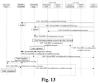
- Implementation scenario 1 the above RRC reconfiguration message is carried respectively by two downlink messages, and a difference from an existing method is that signaling carrying the second RRC reconfiguration message is transmitted before signaling carrying the first RRC reconfiguration message.
- the first IAB-node receives the first RRC reconfiguration message and before the first IAB-node is handed over to the second parent node, the RRC reconfiguration message transmitted by donor-CU for its child node has been transmitted to the first IAB-node and, the RRC reconfiguration message is buffered by the first IAB-node and is forwarded when the first IAB-node is handed over to the second parent node, thereby the first IAB-node and its child node may perform network topology adaptation simultaneously.
- FIG. 13 is a schematic diagram of the message transmission method. As shown in FIG. 13 , the method includes:
- the method may further include:
- the second RRC reconfiguration message is carried by a first downlink F1AP message, and a distribution unit (DU) of the first IAB-node receives the first downlink F1AP message transmitted by the donor-CU, thereby receiving the second RRC reconfiguration message carried by the first downlink F1AP message.
- the first downlink F1AP message further includes first buffer indication information. The first buffer indication information is used to instruct the first IAB-node to buffer the second RRC reconfiguration message and release it until the first indication information (which will be described later) is received.
- the first downlink F1AP message may be a UE context modification request message.
- the first RRC reconfiguration message is carried by a downlink F1AP message transmitted by the donor-CU to the first parent node, and the first parent node forwards the first RRC reconfiguration message in the downlink F1AP message to the first IAB-node.
- the F1AP message may be a UE context modification request message.
- the downlink F1AP message may further include a first context identifier of the UE, and reference may be made to existing techniques for details, which shall not be elaborated herein any further.
- the first IAB-node performs a random access process in 1304, and reference may be made to existing techniques for an implementation thereof, which shall not be repeated herein any further.
- the random access is successful, that is, after an MT (MAC layer) of the first IAB-node completes the random access to the second parent node, in 1305, the first IAB-node forwards the second RRC reconfiguration message to the second IAB-node.
- MT MAC layer
- the mobile terminal (MT) of the first IAB-node when random access of the mobile terminal (MT) of the first IAB-node is successful, it transmits the first indication information to the distribution unit (DU) of the first IAB-node; and when the distribution unit (DU) of the first IAB-node receives the first indication information, it forwards the second RRC reconfiguration message to the second IAB-node.
- the first RRC reconfiguration message contains a first parameter configured for the first IAB-node to change a transmission path and/or contains first path migration indication information, it indicates that the first RRC reconfiguration message is used for path migration of the first IAB-node.
- the MT of the first IAB-node transmits first indication information to the DU of the first IAB-node, and reference may be made to the embodiments of the first aspect for meaning(s) of the first parameter and/or the first path migration indication information, which shall not be repeated herein any further.
- the first RRC reconfiguration message further includes configuration information of the first indication information, the configuration information of the first indication information being used to instruct the MT of the first IAB-node to transmit the first indication information to the distribution unit (DU) of the first IAB-node when the random access is successful.
- the MT of the first IAB-node transmits the first indication information to the DU of the first IAB-node; or, when the first RRC reconfiguration message contains the first parameter and/or the first path migration indication information and the configuration information containing the first indication information, the MT of the first IAB-node transmits the first indication information to the DU of the first IAB-node.
- the DU of the first IAB-node forwards the second RRC reconfiguration message to the second IAB-node when receiving the first indication information.
- the above-described first indication information, configuration information of the first indication information, first buffer indication information and the first path migration indication information may be information elements (IEs) newly added in a message, and values thereof may be default values; however, the embodiments of this disclosure are not limited thereto.
- IEs information elements
- the third RRC reconfiguration message is carried by a second downlink F1AP message, and a distribution unit (DU) of the second IAB-node receives the second downlink F1AP message transmitted by the donor-CU, thereby receiving the third RRC reconfiguration message carried by the second downlink F1AP message.
- the second downlink F1AP message further includes second buffer indication information, the second buffer indication information being used to instruct the second IAB-node to buffer the third RRC reconfiguration message and release it until the second indication information (which is described above) is received.
- the second IAB-node when the second IAB-node receives the second RRC reconfiguration message forwarded by the first IAB-node in 1306, the second IAB-node forwards the third RRC reconfiguration message to the third IAB-node.
- the mobile terminal (MT) of the second IAB-node when the mobile terminal (MT) of the second IAB-node receives the second RRC reconfiguration message, it transmits the second indication information to the distribution unit (DU) of the second IAB-node, and when the distribution unit (DU) of the second IAB-node receives the second indication information, it forwards the third RRC reconfiguration message to the third IAB-node.
- the second RRC reconfiguration message contains a second parameter configured for the second IAB-node to change a transmission path and/or contains second path migration indication information
- the MT of the second IAB-node transmits second indication information to the DU of the second IAB-node.
- the second RRC reconfiguration message further includes configuration information of the second indication information, the configuration information of the second indication information being used to indicate that the second IAB-node may transmit the second indication information to the distribution unit (DU) of the second IAB-node when receiving the second RRC reconfiguration message.
- the MT of the second IAB-node transmits the second indication information to the DU of the second IAB-node; or, when the second RRC reconfiguration message contains the second parameter and/or the second path migration indication information and the configuration information containing the second indication information, the MT of the second IAB-node transmits the second indication information to the DU of the second IAB-node.
- the DU of the second IAB-node forwards the third RRC reconfiguration message to the third IAB-node when receiving the second indication information.
- the above-described second indication information, configuration information of the second indication information, second buffer indication information and the second path migration indication information may be information elements (IEs) newly added in a message, and values thereof may be default values; however, the embodiments of this disclosure are not limited thereto.
- IEs information elements
- the method when the random access of the first IAB-node is successful, the method further includes:
- the first IAB-node transmits the first RRC reconfiguration complete message to the second parent node, and the second parent node forwards the first RRC reconfiguration complete message to the donor-CU, wherein the second parent node may transmit an uplink F1AP message to the donor-CU, the uplink F1AP message carrying the first RRC reconfiguration complete message, and reference may be made to existing techniques for details.
- the second IAB-node transmits the second RRC reconfiguration complete message to the first IAB-node, and the first IAB-node forwards the second RRC reconfiguration complete message to the donor-CU, wherein the first IAB-node may transmit a first uplink F1AP message to the donor-CU, the first uplink F1AP message carrying the second RRC reconfiguration complete message.
- the third IAB-node transmits the third RRC reconfiguration complete message to the second IAB-node, and the second IAB-node forwards the third RRC reconfiguration complete message to the donor-CU, wherein the second IAB-node may transmit a second uplink F1AP message to the donor-CU, the second uplink F1AP message carrying the third RRC reconfiguration complete message.
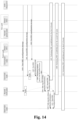
- FIG. 14 is a schematic diagram of the message transmission method. As shown in FIG. 14 , the method includes:
- the method may further include:
- the method may further include:
- T304 when T304 expires, it indicates that the random access fails, or is not completed, or is unsuccessful.
- the first IAB-node transmits the path migration failure indication information to the second IAB-node.
- the first RRC reconfiguration message further includes configuration information of the path migration failure indication information, the configuration information of the path migration failure indication information being used to indicate that the first IAB-node may transmit the path migration failure indication information to the second IAB-node when the random access fails.
- the first IAB-node when the random access of the first IAB-node fails, if the first RRC reconfiguration message contains the configuration information of the path migration failure indication information, the first IAB-node transmits the path migration failure indication information to the second IAB-node, or if the first RRC reconfiguration message contains the first parameter and/or the first path migration indication information and the configuration information of the path migration failure indication information, the first IAB-node transmits the path migration failure indication information to the second IAB-node.
- the first IAB-node forwards the second RRC reconfiguration message to the second IAB-node, or clears the second RRC reconfiguration message.
- This step is optional, and the embodiments of this disclosure is not limited thereto.
- implementations of 1409-1411 are similar to those of 1406-1408, which shall not be repeated herein any further.
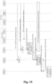
- FIG. 15 is a schematic diagram of the message transmission method. As shown in FIG. 15 , the method includes:
- the first IAB-node does not optionally forward the second RRC reconfiguration message to the second IAB-node, but necessarily forwards, that is, 1507 is a necessary step; otherwise, a packet data aggregation protocol (PDCP) of the second IAB-node may be abnormal.
- PDCP packet data aggregation protocol
- Implementation scenario 2 a difference from implementation scenario 1 is that the above RRC reconfiguration messages are carried by one downlink message, which may not only reduce service interruption timing but also save signaling overhead.
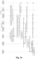
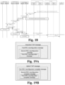
- FIG. 16 is a schematic diagram of the message transmission method. As shown in FIG. 16 , the method includes:
- the method may further include:
- the second RRC reconfiguration message is carried by the first RRC reconfiguration message
- the third RRC reconfiguration message is contained in the second RRC reconfiguration message.
- Contents of information elements contained in the RRC reconfiguration messages are as described above, which shall not be repeated herein any further.
- the donor-CU carries all the first RRC reconfiguration message, the second RRC reconfiguration message and the third RRC reconfiguration message in one downlink F1AP message.
- the downlink F1AP message may be a UE CONTEXT SETUP REQUEST message.
- the UE CONTAXT SETUP REQUEST message may further include a first context identifier of the above UE. Reference may be made to existing techniques for details, which shall not be repeated herein any further.
- FIG. 19A is a schematic diagram of a structure of the downlink F1AP message.
- the first RRC reconfiguration message is carried by the downlink F1AP message transmitted by donor-CU to the first parent node
- the second RRC reconfiguration message is contained in the first RRC reconfiguration message
- the third RRC reconfiguration message is contained in the second RRC reconfiguration message.
- the first RRC reconfiguration message further includes identification information of the second IAB-node, the identification information being a parent node cell identifier of the second IAB-node (such as a DU cell identifier of the first IAB-node) and a cell radio network temporary identifier (C-RNTI) of the second IAB-node in the parent node cell (such as a CNTI of the MT of the second IAB-node in a DU cell of the first IAB-node), or, the identification information being a UE F1AP identifier of the second IAB-node in its parent node (such as a DU UE F1AP ID of the MT of the second IAB-node in the DU of the first IAB-node).
- the identification information being a parent node cell identifier of the second IAB-node (such as a DU cell identifier of the first IAB-node) and a cell radio network temporary
- the second RRC reconfiguration message further contains identification information of the third IAB-node, the identification information being a parent node cell identifier of the third IAB-node (such as a DU cell identifier of the second IAB-node) and a cell radio network temporary identifier (C-RNTI) of the third IAB-node in the parent node cell (such as a CNTI of the MT of the third IAB-node in a DU cell of the second IAB-node), or, the identification information being a UE F1AP identifier of the third IAB-node in its parent node (such as a DU UE F1AP ID of the MT of the third IAB-node in the DU of the second IAB-node).
- the identification information being a parent node cell identifier of the third IAB-node (such as a DU cell identifier of the second IAB-node) and a cell radio network temporary
- the first parent node transmits the first RRC reconfiguration message therein to the first IAB-node.
- the first IAB-node extracts the second RRC reconfiguration message from the first RRC reconfiguration message and forwards it to the second IAB-node.
- the second IAB-node extracts the third RRC reconfiguration message therefrom and forwards it to the third IAB-node.
- the mobile terminal (MT) of the first IAB-node when the mobile terminal (MT) of the first IAB-node is successful in the random access, it transmits the second RRC reconfiguration message to the DU of the first IAB-node, and then forwards it to the second IAB-node.
- the first RRC reconfiguration message contains the first parameter configured for the first IAB-node to change a transmission path and/or contains the first path migration indication information, it indicates that the first RRC reconfiguration message is used for path migration of the first IAB-node, and the MT of the first IAB-node transmits the second RRC reconfiguration message to the DU of the first IAB-node.
- the mobile terminal (MT) of the second IAB-node transmits the third RRC reconfiguration message to the DU of the second IAB-node, and then forwards it to the third IAB-node.
- the second RRC reconfiguration message contains the second parameter configured for the second IAB-node to change a transmission path and/or contains the second path migration indication information
- it indicates that the second RRC reconfiguration message is used for path migration of the second IAB-node
- the MT of the second IAB-node transmits the third RRC reconfiguration message to the DU of the second IAB-node.
- the third RRC reconfiguration message is used for path migration of the third IAB-node.
- the third RRC reconfiguration message contains a third parameter configured for the third IAB-node to change a transmission path.
- the third IAB-node may perform path migration. Reference may be made to existing techniques for operations of path migration, and a meaning of the third parameter is similar to that of the first parameter, which shall not be repeated herein any further.
- the third RRC reconfiguration message may further include a fourth RRC reconfiguration message for path migration of its child node.
- the third IAB-node forwards the fourth RRC reconfiguration message therein to its child node. Implementation of forwarding is identical to that of the second IAB-node, which shall not be repeated herein any further.
- the donor-CU does not need to transmit a downlink F1AP message respectively for the first IAB-node, the second IAB-node and the third IAB-node.
- This may save signaling overhead, and through layer by layer message forwarding, the first IAB-node, the second IAB-node and the third IAB-node may almost simultaneously receive respective RRC reconfiguration messages.
- the random access is successful (random access to the second parent node is successful)
- the first IAB-node performs message forwarding, thereby making the first IAB-node, the second IAB-node and the third IAB-node to simultaneously perform network topology adaptation, and reducing service interruption timing.
- the method may further include:
- FIG. 17 is another schematic diagram of the message transmission method, which is different from FIG. 16 in that the RRC reconfiguration complete messages of the IAB-nodes are not transmitted via different uplink messages, but are carried by the second parent node via the same uplink F1AP message and transmitted to the donor-CU, thereby further reducing signaling overhead.
- the method includes operations 1701, 1702, 1703, 1704 and 1705 identical to operations 1601-1605 in FIG. 16 .
- the method may include:
- the second IAB-node includes the third RRC reconfiguration complete message in the second RRC reconfiguration complete message and transmits it to the first IAB-node
- the first IAB-node includes the second RRC reconfiguration complete message in the first RRC reconfiguration complete message and transmits it to the second parent node
- the second parent node transmits an uplink F1AP message to the donor-CU, the uplink F1AP message carrying the first RRC reconfiguration complete message.
- FIG. 19B is a schematic diagram of a structure of the uplink F1AP message.
- the first RRC reconfiguration complete message is carried by the uplink F1AP message transmitted by the second parent node to the donor-CU
- the second RRC reconfiguration complete message is included in the first RRC reconfiguration complete message
- the third RRC reconfiguration complete message is included in the second RRC reconfiguration complete message.
- the first RRC reconfiguration complete message further includes identification information of the second IAB-node.
- the second RRC reconfiguration complete message further contains identification information of the third IAB-node. The identification information is as described above, and shall not be described herein any further.
- the third IAB-node completes RRC reconfiguration, transmits the third RRC reconfiguration complete message to the second IAB-node, and performs F1 transmission path migration;
- the second IAB-node receives the third RRC reconfiguration complete message, completes RRC reconfiguration of its own, includes the third RRC reconfiguration complete message in the second RRC reconfiguration complete message, transmits it to the first IAB-node, and achieve F1 transmission path migration;
- the first IAB-node receives the second RRC reconfiguration complete message, completes RRC reconfiguration of its own, includes the second RRC reconfiguration complete message in the first RRC reconfiguration complete message, transmits it to its second parent node, and achieves F1 transmission path migration.
- the second parent node carries the first RRC reconfiguration complete message via an uplink F1AP message, and transmits it to the donor-CU.
- the uplink RRC messages of the child node of the IAB-node are carried by F1AP and are transmitted via a backhaul RLC channel (i.e. forwarded by a BAP layer), hence, there is no need to wait for the RRC reconfiguration complete message of the child node to be received before transmitting the RRC reconfiguration complete message of its own. Therefore, in order to carry the RRC reconfiguration complete messages of the IAB-nodes via one uplink F1AP message, the first RRC reconfiguration message may further include complete message transmission occasion configuration information, which is used to indicate that the first IAB-node transmits the RRC reconfiguration complete message of its own after receiving the RRC reconfiguration complete message transmitted by the child node.
- the first RRC reconfiguration complete message transmitted by the first IAB-node is a first uplink data transmitted by the first IAB-node by using the new F1 transmission path.
- the first IAB-node may transmit the first RRC reconfiguration complete message only after receiving the second RRC reconfiguration complete message. Therefore, the first IAB-node shall not use the new F 1 transmission path to transmit other uplink data in a period from receiving the first RRC reconfiguration message to transmitting the first RRC reconfiguration complete message.
- the first IAB-node when the first IAB-node receives the first RRC reconfiguration message, it suspends all uplink transmissions (including scheduling requests and buffer status reports), including transmission of data radio bearers and BH RLC channels.
- the first RRC reconfiguration complete message After transmitting the first RRC reconfiguration complete message, it recovers the transmission of data radio bearers and BH RLC channels, or, after receiving the second RRC reconfiguration complete message, it recovers uplink transmission. At this moment, as a priority of an RRC signaling message is higher than that of data, after the uplink transmission is recovered, it may be ensured that the first RRC reconfiguration complete message is preferentially transmitted.
- FIGs. 16-17 show the information exchange of the IAB-nodes when the random access of the first IAB-node is successful.
- the method may further include: 1405-1411 or 1505-1511 in implementation scenario 1, with repeated parts being not going to be described herein any further.
- Implementation scenario 3 a difference from implementation scenario 2 is that a message structure of the downlink F1AP message transmitted by the donor-CU to the first parent node is different.
- FIG. 20A is a schematic diagram of the structure of the downlink F1AP message.
- the downlink F1AP message carries the first RRC reconfiguration message
- the first RRC reconfiguration message contains a third downlink F1AP message transmitted by the donor-CU to the first IAB-node
- the second RRC reconfiguration message is carried by the third downlink F1AP message
- the second RRC reconfiguration message contains a fourth downlink F1AP message transmitted by the donor-CU to the second IAB-node
- the third RRC reconfiguration message is carried by the fourth downlink F1AP message.
- the third downlink F1AP message further includes identification information of the second IAB-node (such as a DU UE F1AP ID of the second IAB-node), and the fourth downlink F1AP message further includes identification information of the third IAB-node (such as a DU UE F1AP ID of the third IAB-node).
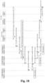
- FIG. 18 is a schematic diagram of the message transmission method. As shown in FIG. 18 , the method includes:
- the first RRC reconfiguration message when the first RRC reconfiguration message contains a first parameter configured for the first IAB-node to change a transmission path and/or contains first path migration indication information, it indicates that the first RRC reconfiguration message is used for path migration of the first IAB-node.
- the MT of the first IAB-node extracts the third downlink F1AP message from the first RRC reconfiguration message and transmits the third downlink F1AP message to the DU of the first IAB-node, and reference may be made to the embodiments of the first aspect for meaning(s) of the first parameter and/or the first path migration indication information, which shall not be repeated herein any further.
- the second RRC reconfiguration message contains a second parameter configured for the second IAB-node to change a transmission path and/or contains second path migration indication information
- the MT of the second IAB-node extracts the fourth downlink F1AP message from the second RRC reconfiguration message and transmits the fourth downlink F1AP message to the DU of the second IAB-node.
- the third RRC reconfiguration message is used for path migration of the third IAB-node. Therefore, the third RRC reconfiguration message contains a third parameter configured for the third IAB-node to changes a transmission path. After receiving the third RRC configuration message, the third IAB-node may perform path migration. Reference may be made to existing techniques for operations of the path migration may, and a meaning of the third parameter is similar to that of the first parameter, which shall not be repeated herein any further.
- the third RRC reconfiguration message may further include a fifth downlink F1AP message, the fifth downlink F1AP message including a fourth RRC reconfiguration message for path migration of its child node.
- the third IAB-node forwards the fourth RRC reconfiguration message therein to its child node, and implementation of the forwarding is identical to that of the second IAB-node, which shall not be described herein any further.
- the third IAB-node performs path migration after receiving the third RRC reconfiguration message, and does not need to perform forwarding actions. Reference may be made to existing technologies for details, which shall not be repeated herein any further.
- the donor-CU does not need to transmit a downlink F1AP message respectively for the first IAB-node, the second IAB-node and the third IAB-node.
- This may save signaling overhead, and through layer by layer message forwarding, the first IAB-node, the second IAB-node and the third IAB-node may almost simultaneously receive respective RRC reconfiguration messages.
- the random access is successful (random access to the second parent node is successful)
- the first IAB-node performs message forwarding, thereby making the first IAB-node, the second IAB-node and the third IAB-node to simultaneously perform network topology adaptation, and reducing service interruption timing.
- the downlink F1AP message in FIG. 20A may be a UE CONTENT SETUP REQUEST message.
- the UE CONTAXT SETUP REQUEST message may include topology-related reconfiguration information reconfigured for the BH RLC channel of the first IAB-node, the reconfiguration information including backhaul RLC channel mapping relationship reconfiguration information, and/or backhaul RLC channel modification information between the first IAB-node and its child node.
- the backhaul RLC channel mapping relationship reconfiguration information refers to a mapping relationship between a BH RLC channel between the first IAB-node and the second IAB-node and a BH RLC channel between the first IAB-node and the second parent node
- the backhaul RLC channel modification information refers to information related to addition, modification and deletion of the BH RLC channel between the first IAB-node and the second IAB-node, for example, the modification information includes modifying a quality of service (QoS) parameter of the BH RLC channel.
- QoS quality of service
- Another difference between this embodiment and implementation scenario 2 is that the message structure of the uplink F1AP message transmitted by the second parent node to donor-CU is different.
- FIG. 20B is a schematic diagram of the structure of the uplink F 1AP message. As shown in FIG.
- the third RRC reconfiguration complete message is carried by a fourth uplink F1AP message of the second IAB-node, the fourth uplink F1AP message being carried by the second RRC reconfiguration complete message, the second RRC reconfiguration complete message is carried by a third uplink F1 AP message of the first IAB-node, the third uplink F1AP message being carried by the first RRC reconfiguration complete message, and the first RRC reconfiguration complete message is contained in an uplink F1AP message transmitted by the second parent node to the donor-CU (such as UL RRC MESSAGE TRNASFOR).
- the third uplink F1AP message includes the identification information of the second IAB-node
- the fourth uplink F1AP message includes the identification information of the third IAB-node. Implementation of the identification information is consistent with the identification information in the downlink F1AP message, and shall not be repeated herein any further.
- the method may further include:
- the third IAB-node completes RRC reconfiguration, transmits the third RRC reconfiguration complete message to the second IAB-node, and performs F1 transmission path migration;
- the second IAB-node receives the third RRC reconfiguration complete message, completes RRC reconfiguration of its own, contains the third RRC reconfiguration complete message in the fourth uplink F1AP message, and contains the fourth F1AP message in the second RRC reconfiguration complete message, and transmits it to the first IAB-node to achieve F1 transmission path migration;
- the first IAB-node receives the second RRC reconfiguration complete message, completes RRC reconfiguration of its own, contains the second RRC reconfiguration complete message in the third uplink F1AP message, and contains the third F1AP message in the first RRC reconfiguration complete message, and transmits the third F1AP message to its second parent node to achieve F1 transmission path migration.
- the second parent node carries the first RRC reconfiguration complete message via one uplink F1AP message
- the uplink RRC messages of the child node of the IAB-node are carried by an F1AP and transmitted via a backhaul RLC channel (i.e. forwarded by a BAP layer), hence, there is no need to wait for the RRC reconfiguration complete message of the child node to be received before transmitting the RRC reconfiguration complete message of its own. Therefore, in order to carry RRC reconfiguration complete messages of the IAB-nodes via one uplink F1AP message, the first RRC reconfiguration message may further include complete message transmission occasion configuration message, which is used to indicate that the first IAB-node transmits the RRC reconfiguration complete message of its own after receiving the RRC reconfiguration complete message transmitted by the child node.
- the first RRC reconfiguration complete message transmitted by the first IAB-node is a first uplink data transmitted by the first IAB-node by using the new F1 transmission path.
- the first IAB-node may transmit the first RRC reconfiguration complete message only after receiving the second RRC reconfiguration complete message.
- the first IAB-node shall not use the new F1 transmission path to transmit other uplink data in a period from receiving the first RRC reconfiguration message to transmitting the first RRC reconfiguration complete message.
- the first IAB-node when the first IAB-node receives the first RRC reconfiguration message, it suspends all uplink transmissions (including scheduling requests and buffer status reports), including transmission of data radio bearers and BH RLC channel.
- the first RRC reconfiguration complete message After transmitting the first RRC reconfiguration complete message, it recovers the transmission of data radio bearers and BH RLC channel, or after receiving the second RRC reconfiguration complete message, and at this moment, it recovers uplink transmission, and at this moment, as a priority of an RRC signaling message is higher than that of the data, after the uplink transmission is recovered, it may be ensured that the first RRC reconfiguration complete message is transmitted preferentially.
- FIG. 18 shows the information exchange between the IAB-nodes when the random access of the first IAB-node is successful. And when the random access of the first IAB-node fails, the method may further include: 1405-1411 or 1505-1511 in implementation scenario 1, which shall not be repeated herein any further.
- FIGs. 8-18 only schematically illustrates the embodiments of this disclosure; however, this disclosure is not limited thereto. For example, an order of execution of the steps may be appropriately adjusted, and furthermore, some other steps may be added, or some steps therein may be reduced. And appropriate variants may be made by those skilled in the art according to the above contents, without being limited to what is contained in FIGs. 8-18 .
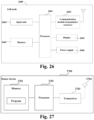
- the embodiments of this disclosure provide a message transmission apparatus.
- FIG. 21 is a schematic diagram of the message transmission apparatus of the embodiment of this disclosure.
- the apparatus may be, for example, an IAB-node in an IAB system, or one or some components or assemblies configured in the IAB-node.
- the IAB system includes a donor device and an IAB-node, and the embodiments of this disclosure shall be explained from a first IAB-node side.
- An implementation principle of the message transmission apparatus in the embodiments of this disclosure is similar to that in the embodiments of the first aspect, with identical parts being not going to be repeated herein any further.
- a message transmission apparatus 2100 of this disclosure embodiment includes:
- reference of the first receiving unit 2101, the second receiving unit 2102, the first transmitting unit 2103 may be made to implementations of 801-803 in the embodiments of the first aspect and the first IAB-node in implementation scenarios 1-3, which shall not be repeated herein any further.
- the second RRC reconfiguration message is carried by a first downlink F1AP message transmitted by the donor-CU.
- the first transmitting unit 2103 includes a first transmitting module and a second transmitting module (not shown in figures), wherein when random access of a mobile terminal (MT) of the first IAB-node is successful, the first transmitting module transmits first indication information to a distribution unit (DU) of the first IAB-node, and the second transmitting module forwards the second RRC reconfiguration message to the second IAB-node when the distribution unit (DU) of the first IAB-node receives the first indication information.
- MT mobile terminal
- DU distribution unit
- the second transmitting module forwards the second RRC reconfiguration message to the second IAB-node when the distribution unit (DU) of the first IAB-node receives the first indication information.
- the first transmitting module on the MT of the first IAB-node transmits the first indication information to the DU of the first IAB-node.
- the first parameter configured for the first IAB-node to change a transmission path includes a default backhaul RLC channel, or a default BAP route, or an IP address, configured for the first IAB-node.
- the first transmitting module on the MT of the first IAB-node transmits the first indication information to the DU of the first IAB-node, the first path migration indication information indicating that the first RRC reconfiguration message is a reconfiguration message for the first IAB-node to perform path migration.
- the first RRC reconfiguration message further includes configuration information of the first indication information, the configuration information of the first indication information being used to instruct the first transmitting module to transmit the first indication information to the distribution unit (DU) of the first IAB-node when the random access of the MT of the first IAB-node is successful.
- the configuration information of the first indication information being used to instruct the first transmitting module to transmit the first indication information to the distribution unit (DU) of the first IAB-node when the random access of the MT of the first IAB-node is successful.
- the first downlink F1AP message further includes first buffer indication information, the first buffer indication information being used to instruct the first IAB-node to buffer the second RRC reconfiguration message and release it until the first indication information is received.
- the second RRC reconfiguration message is carried by the first RRC reconfiguration message.
- the first RRC reconfiguration message further includes identification information of the second IAB-node.
- the second RRC reconfiguration message is carried by a third downlink F1AP message from the donor-CU, the third downlink F1AP message being carried by the first RRC reconfiguration message.
- the third downlink F1AP message further includes the identification information of the second IAB-node.
- the first transmitting unit 2103 includes a third transmitting module and a fourth transmitting module (not shown in figures), wherein when the random access of the MT of the first IAB-node is successful, the third transmitting module transmits third downlink F1AP message to the DU of the first IAB-node, and the fourth transmitting module forwards the second RRC reconfiguration message to the second IAB-node when the DU of the first IAB-node receives the third downlink F1AP message.
- the first transmitting unit 2103 further transmits path migration failure indication information to the second IAB-node when the random access of the first IAB-node fails.
- the apparatus further includes a first processing unit (not shown in figures) configured to forward the second RRC reconfiguration message to the second IAB-node, or clear the second RRC reconfiguration message.
- a first processing unit (not shown in figures) configured to forward the second RRC reconfiguration message to the second IAB-node, or clear the second RRC reconfiguration message.
- the first transmitting unit 2103 transmits the path migration failure indication information to the second IAB-node.
- the first RRC reconfiguration message further includes configuration information of the path migration failure indication information, the configuration information of the path migration failure indication information being used to indicate that the first IAB-node transmits the path migration failure indication information to the second IAB-node when the random access fails.
- the apparatus when the random access of the first IAB-node is successful, the apparatus further includes a second transmitting unit 2104 and a third receiving unit 2105 (optional).
- the second transmitting unit 2104 transmits a first RRC reconfiguration complete message to the donor-CU, and the third receiving unit 2105 receives a second RRC reconfiguration complete message transmitted by the second IAB-node.
- the second transmitting unit 2104 forwards the second RRC reconfiguration complete message to the donor-CU, the second RRC reconfiguration complete message being carried by the first uplink F1AP message.
- the second transmitting unit 2104 contains the second RRC reconfiguration complete message in the first RRC reconfiguration complete message and forwards it to the donor-CU.
- the second transmitting unit 2104 includes a first receiving module, a fifth transmitting module and a sixth transmitting module that are not shown in figures.
- the first receiving module on the DU of the first IAB-node receives the second RRC reconfiguration complete message transmitted by the second IAB-node
- the fifth transmitting module on the DU of the first IAB-node transmits a third uplink F1AP message containing the second RRC reconfiguration complete message to the MT of the first IAB-node
- the sixth transmitting module on the MT of the first IAB-node contains the third uplink F1AP message in the first RRC reconfiguration complete message and forwards it to the donor-CU.
- connection relationships between the components or modules or signal profiles thereof are only illustrated in FIG. 21 .
- connection relationships between the components or modules or signal profiles thereof are only illustrated in FIG. 21 .
- such related techniques as bus connection, etc. may be adopted.
- the above components or modules may be implemented by hardware, such as a processor, a memory, a transmitter, and a receiver, etc., which are not limited in the embodiments of this disclosure.
- the information related to the network topology adaptation configured for its child node is transmitted by the donor-CU to the IAB-node and buffered in the IAB-node.
- the IAB-node forwards the information related to the network topology adaptation configured by the donor-CU for its child node to its child node.
- the IAB-node and its child node may be made to perform network topology adaptation almost simultaneously, thereby reducing service interruption timing resulted from node migration.
- the embodiments of this disclosure provide a message transmission apparatus.
- FIG. 22 is a schematic diagram of the message transmission apparatus of the embodiment of this disclosure.
- the apparatus may be, for example, an IAB-node in an IAB system, or one or some components or assemblies configured in the IAB-node.
- the IAB system includes a donor device and an IAB-node, and the embodiments of this disclosure shall be explained from a second IAB-node side.
- An implementation principle of the message transmission apparatus in the embodiments of this disclosure is similar to that in the embodiments of the second aspect, with identical parts being not going to be repeated herein any further.
- a message transmission apparatus 2200 of this disclosure embodiment includes:
- the third RRC reconfiguration message is carried by a second downlink F1AP message transmitted by the donor-CU.
- the third transmitting unit 2202 includes a seventh transmitting module and an eight transmitting module that are not shown in figures, wherein the seventh transmitting module transmits second indication information to a DU of the second IAB-node when the MT of the second IAB-node receives the second RRC reconfiguration message, and the eight transmitting module forwards the third RRC reconfiguration message to the third IAB-node when the DU of the second IAB-node receives the second indication information.
- the seventh transmitting module on the MT of the second IAB-node transmits second indication information to the DU of the second IAB-node.
- the second parameter configured for the second IAB-node to change a transmission path includes a default backhaul RLC channel, or a default BAP route, or an IP address, configured for the second IAB-node.
- the seventh transmitting module on the MT of the second IAB-node transmits the second indication information to the DU of the second IAB-node, the second path migration indication information being used to indicate that the second RRC reconfiguration message is a reconfiguration message for the second IAB-node to perform path migration.
- the apparatus is applied when the donor-DU is changed after the first IAB-node is handed over to the new parent node, the second RRC reconfiguration message is used for path migration of the second IAB-node between donor-DUs.
- the second path migration indication information is used to indicate that the second IAB-node is performing path migration between donor-DUs, that is, when the second RRC message contains the second path migration indication information, it indicates that the second RRC reconfiguration message is a reconfiguration message for the second IAB-node to perform path migration between different donor-DUs.
- the second RRC reconfiguration message further includes configuration information of the second indication information, the configuration information of the second indication information being used to indicate that the MT of the second IAB-node transmits the second indication information to the distribution unit (DU) of the second IAB-node when receiving the second RRC reconfiguration message.
- the second downlink F 1AP message further includes second buffer indication information, the second buffer indication information being used to instruct the second IAB-node to buffer the third RRC reconfiguration message and release it until the second indication information is received.
- the third RRC reconfiguration message is included in the second RRC reconfiguration message transmitted by the donor-CU and forwarded by the first IAB-node.
- the second RRC reconfiguration message further includes identification information of the third IAB-node.
- the third RRC reconfiguration message is carried by a fourth downlink F1AP message transmitted by the donor-CU, the fourth downlink F1AP message being carried by the third RRC reconfiguration message.
- the fourth downlink F1AP message further includes identification information of the third IAB-node.
- the third transmitting unit 2202 includes a ninth transmitting module and a tenth transmitting module that are not shown in figures.
- the ninth transmitting module transmits the fourth downlink F1AP message to the DU of the second IAB-node, and when the DU of the second IAB-node receives the fourth downlink F1AP message, the tenth transmitting module forwards the third RRC reconfiguration message in the fourth downlink F1AP message to the third IAB-node.
- the apparatus when the second IAB-node receives the second RRC reconfiguration message, the apparatus further includes: a fourth transmitting unit 2203 and a fifth receiving unit 2204 (optional), wherein the fourth transmitting unit 2203 transmits a second RRC reconfiguration complete message to the first IAB-node, and the fifth receiving unit 2204 receives the third RRC reconfiguration complete message transmitted by the third IAB-node.
- the fourth transmitting unit 2203 is further configured to forward the third RRC reconfiguration complete message to the donor-CU, the third RRC reconfiguration complete message being carried by the second uplink F1AP message.
- the fourth transmitting unit 2203 is further configured to include the third RRC reconfiguration complete message in the second RRC reconfiguration complete message and forward it to the donor-CU.
- the fourth transmitting unit 2203 further includes a second receiving module, an eleventh transmitting module and a twelfth transmitting module that are not shown in figures, wherein the second receiving module on the DU of the second IAB-node receives the third RRC reconfiguration complete message transmitted by the third IAB-node, the eleventh transmitting module on the DU of the second IAB-node transmits the fourth uplink F1AP message containing the third RRC reconfiguration complete message to the MT of the second IAB-node, and the twelfth transmitting module on the MT of the IAB-node contains the fourth uplink F1AP message in the second RRC reconfiguration complete message and forwards it to the donor-CU.
- the information related to the network topology adaptation configured for its child node is transmitted by the donor-CU to the IAB-node and buffered in the IAB-node.
- the IAB-node forwards the information related to the network topology adaptation configured by the donor-CU for its child node to its child node.
- the IAB-node forwards the information related to the network topology adaptation configured by the donor-CU for its child node to its child node.
- the IAB-node forwards the information related to the network topology adaptation configured by the donor-CU for its child node to its child node.
- FIG. 23 is a schematic diagram of the message transmission apparatus of the embodiment of this disclosure.
- the apparatus may be, for example, an IAB-node in an IAB system, or one or some components or assemblies configured in the IAB-node.
- the IAB system includes a donor device and an IAB-node, and the embodiments of this disclosure shall be explained from a second IAB-node side.
- An implementation principle of the message transmission apparatus in the embodiments of this disclosure is similar to that in the embodiments of the second aspect, with identical parts being not going to be repeated herein any further.
- a message transmission apparatus 2300 of this disclosure embodiment includes:
- the apparatus further includes a fifth transmitting unit 2304 configured to forward a path migration failure indication information to the third IAB-node.
- the second processing unit 2303 is further configured to forward the third RRC reconfiguration message to the third IAB-node, or clear the third RRC reconfiguration message.
- the third RRC reconfiguration message is carried by a second downlink F1AP message transmitted by the donor-CU.
- the second processing unit 2303 further includes a thirteenth transmitting module and a fourteenth transmitting module, wherein the thirteenth transmitting module on the MT of the second IAB-node transmits second indication information to the DU of the second IAB-node, and when the DU of the second IAB-node receives the second indication information, the fourteenth transmitting module forwards the third RRC reconfiguration message carried by the second downlink F1AP message to the third IAB-node.
- the sixth receiving unit 2301 is further configured to receive the second RRC reconfiguration message for path migration of the second IAB-node transmitted by the donor-CU to the first IAB-node and forwarded by the first IAB-node.
- the random access to the new parent node where the IAB-node is handed over fails, it triggers RRC reestablishment and indicates path migration failure to its child node, and at the same time, its child node also triggers RRC reestablishment.
- the IAB-node fails in migration the IAB-node and its child node may almost simultaneously perform RRC reestablishment, thereby reducing service interruption timing resulted from the path migration failure.
- the random access to the new parent node where the IAB-node is handed over fails, it triggers RRC reestablishment, forwards the RRC reconfiguration of its child node to the child node and indicates path migration failure to its child node, thereby making its child node fall back to original path configuration.
- the IAB-node fails in migration the IAB-node and its child node may simultaneously fall back to the original path configuration. Otherwise, if the child node performs path migration and generates uplink data according to the new path configuration, these uplink data is dropped subsequently and is retransmitted by the UE, thereby resulting in an increase in latency of uplink data transmission. This method may avoid prolonged data transmission timing resulted from path migration failures.
- connection relationships between the components or modules or signal profiles thereof are only illustrated in FIGs. 22 and 23 .
- connection relationships between the components or modules or signal profiles thereof are only illustrated in FIGs. 22 and 23 .
- such related techniques as bus connection, etc. may be adopted.
- the above components or modules may be implemented by hardware, such as a processor, a memory, a transmitter, and a receiver, etc., which are not limited in the embodiments of this disclosure.
- the embodiments of this disclosure provide a message transmission apparatus.
- FIG. 24 is a schematic diagram of the message transmission apparatus of the embodiment of this disclosure.
- the apparatus may be, for example, a donor device in an IAB system, or one or some components or assemblies configured in the donor device.
- the IAB system includes a donor device and an IAB-node, and the embodiments of this disclosure shall be explained from a s donor-CU side.
- An implementation principle of the message transmission apparatus in the embodiments of this disclosure is similar to that in the embodiments of the third aspect, with identical parts being not going to be repeated herein any further.
- FIG. 24 is a schematic diagram of the message transmission apparatus of the embodiment of this disclosure. As shown in FIG. 24 , a message transmission apparatus 2400 of this disclosure embodiment includes:
- the second RRC reconfiguration message is carried by a first downlink F1AP message transmitted by the donor-DU.
- the first RRC reconfiguration message contains a first parameter configured for the first IAB-node to change a transmission path.
- the first parameter includes a default backhaul RLC channel, or a default BAP route, or an IP address, configured for the first IAB-node.
- the first RRC reconfiguration message further includes first path migration indication information, the first path migration indication information indicating that the first RRC reconfiguration message is a reconfiguration message for the first IAB-node to perform path migration.
- the first RRC reconfiguration message further includes configuration information of the first indication information, the configuration information of the first indication information being used to instruct the MT of the first IAB-node to transmit the first indication information to the distribution unit (DU) of the first IAB-node when the random access of the MT of the first IAB-node is successful.
- the configuration information of the first indication information being used to instruct the MT of the first IAB-node to transmit the first indication information to the distribution unit (DU) of the first IAB-node when the random access of the MT of the first IAB-node is successful.
- the first downlink F1AP message further includes first buffer indication information, the first buffer indication information being used to instruct the first IAB-node to buffer the second RRC reconfiguration message and release it until the first indication information is received.
- the second RRC reconfiguration message is carried by the first RRC reconfiguration message.
- the first RRC reconfiguration message further includes identification information of the second IAB-node.
- the second RRC reconfiguration message is carried by a third downlink F1AP message, the third downlink F1AP message being carried by the first RRC reconfiguration message.
- the third downlink F1AP message further includes the identification information of the second IAB-node.
- the first RRC reconfiguration message further includes configuration information of the path migration failure indication information, the configuration information of the path migration failure indication information being used to indicate that the first IAB-node transmits the path migration failure indication information to the second IAB-node when the random access fails.
- the second RRC reconfiguration message contains a second parameter configured for the second IAB-node to change a transmission path.
- the second parameter includes a default backhaul RLC channel, or a default BAP route, or an IP address, configured for the second IAB-node.
- the second RRC reconfiguration message contains second path migration indication information, the second path migration indication information being used to indicate that the second RRC reconfiguration message is a reconfiguration message for the second IAB-node to perform path migration.
- the second RRC reconfiguration message further includes configuration information of the second indication information, the configuration information of the second indication information being used to indicate that the MT of the second IAB-node transmits the second indication information to the DU of the second IAB-node when receiving the second RRC reconfiguration message.
- the apparatus further includes an eighth transmitting unit 2403 (optional) configured to transmit a third RRC reconfiguration message for path migration of the third IAB-node to the second IAB-node.
- the third RRC reconfiguration message is carried by a second downlink F1AP message transmitted by the donor-CU.
- the second downlink F1AP message further includes second buffer indication information, the second buffer indication information being used to instruct the second IAB-node to buffer the third RRC reconfiguration message and release it until the second indication information is received.
- the third RRC reconfiguration message is contained in the second RRC reconfiguration message transmitted by the donor-CU and forwarded by the first IAB-node.
- the second RRC reconfiguration message further includes identification information of the third IAB-node.
- the third RRC reconfiguration message is carried by a fourth downlink F1AP message, the fourth downlink F1AP message being carried by the second RRC reconfiguration message.
- the fourth downlink F1AP message further includes identification information of the third IAB-node.
- the apparatus further includes an eighth receiving unit (optional, not shown in figures) configured to receive a first RRC reconfiguration complete message transmitted by the first IAB-node.
- an eighth receiving unit (optional, not shown in figures) configured to receive a first RRC reconfiguration complete message transmitted by the first IAB-node.
- the eighth receiving unit is further configured to receive a second RRC reconfiguration complete message transmitted by the second IAB-node, the second RRC reconfiguration complete message being carried by the first uplink F1AP message transmitted by the first IAB-node.
- the first RRC reconfiguration complete message further contains a third uplink F1AP message, the third uplink F1AP message containing the second RRC reconfiguration complete message.
- the first RRC reconfiguration complete message further contains a second RRC reconfiguration message.
- connection relationships between the components or modules or signal profiles thereof are only illustrated in FIG. 24 .
- connection relationships between the components or modules or signal profiles thereof are only illustrated in FIG. 24 .
- such related techniques as bus connection, etc. may be adopted.
- the above components or modules may be implemented by hardware, such as a processor, a memory, a transmitter, and a receiver, etc., which are not limited in the embodiments of this disclosure.
- FIG. 25 is a schematic diagram of a communication system 2500.
- the communication system 2500 includes a donor device 2500, IAB-nodes 2501, 2502, 2503, 2504 and 2505, wherein the IAB-node 2503 is a migrating IAB-node (a first IAB-node), the IAB-node 2501 is taken as a source node (a first parent node) of the IAB-node 2503, the IAB-node 2502 is taken as a target node (a second parent node) of the IAB-node 2503, the donor device 2500 is taken as a donor-CU, the IAB-node 2504 is a downstream node of the IAB-node 2503, and the IAB-node 2505 is a downstream node of the IAB-node 2504.
- the IAB-node 2503 is a migrating IAB-node (a first IAB-node)
- the IAB-node 2503 is configured to carry out the method executed by the first IAB-node in the embodiments of the first aspect, and may include the apparatus shown in FIG. 21 .
- the IAB-node 2504 is configured to carry out the method executed by the second IAB-node in the embodiments of the second aspect, and may include the apparatus shown in FIG. 22 or 23 .
- the donor device 2500 is configured to carry out the method executed by the donor-CU in the embodiments of the third aspect, and may include the apparatus shown in FIG. 24 . Reference may be made to the embodiments of the first to third aspects for the relevant contents of the donor device 2500 and the IAB-nodes, which shall not be repeated herein any further.
- the IAB-node 2501 corresponds to the first parent node, and is used to receive the downlink F1AP message containing the first RRC reconfiguration message transmitted by the donor-CU in the embodiments of the first aspect, or receive a downlink F1AP message with a structure as shown in FIG. 19A or 20A , and forwards the first RRC reconfiguration message in the F1AP message to the IAB-node 2503.
- the IAB-node 2502 corresponds to the second parent node, and is used to receive the first RRC reconfiguration complete message transmitted by the IAB-node 2503, contain the first RRC reconfiguration complete message in an uplink F1AP message and transmit it to the donor-CU, the uplink F1AP message having a structure as shown in FIG. 19B or 20B .
- the embodiments of this disclosure further provide an IAB-node.
- FIG. 26 is a schematic diagram of the IAB-node of the embodiment of this disclosure.
- an IAB-node 2600 may include a processor 2601 and a memory 2602, the memory 2602 storing data and programs and being coupled to the processor 2601. It should be noted that this figure is illustrative only, and other types of structures may also be used, so as to supplement or replace this structure and achieve a telecommunications function or other functions.
- the processor 2601 may be configured to execute a program to carry out the method executed by the IAB-node or the first parent node or the second parent node in the embodiments of the first aspect or the second aspect.
- the IAB-node 2600 may further include a communication module 2603, an input unit 2604, a display 2605, and a power supply 2606, wherein functions of the above components are similar to those in the related art, which shall not be described herein any further. It should be noted that the IAB-node 2600 does not necessarily include all the parts shown in FIG. 26 , and the above components are not necessary. Furthermore, the IAB-node 2600 may include parts not shown in FIG. 26 , and the related art may be referred to.
- the embodiments of this disclosure further provide a donor device.
- FIG. 27 is a schematic diagram of the donor device of the embodiment of this disclosure.
- a donor device 2700 may include a processor (such as a central processing unit (CPU)) 2701 and a memory 2702, the memory 2702 being coupled to processor 2701.
- the memory 2702 may store various data, and furthermore, it may store a program for information processing, and execute the program under control of the central processing unit 2701.
- the processor 2701 may be configured to execute a program to carry out the method as described in the embodiments of the third aspect.
- the donor device 2700 may include a transceiver 2703, and an antenna 2704, etc., wherein functions of the above components are similar to those in the related art, which shall not be described herein any further. It should be noted that the donor device 2700 does not necessarily include all the components shown in FIG. 27 ; and furthermore, the donor device 2700 may include components not shown in FIG. 27 , and the related art may be referred to.
- An embodiment of this disclosure provides a computer readable program, which, when executed in an IAB-node, will cause a computer to carry out the method in the embodiments of the first or second aspect in the IAB-node.
- An embodiment of this disclosure provides a computer storage medium, including a computer readable program, which will cause a computer to carry out the method in the embodiments of the first or second aspect in the IAB-node.
- An embodiment of this disclosure provides a computer readable program, which, when executed in a donor device, will cause a computer to carry out the method in the embodiments of the third aspect in the donor device.
- An embodiment of this disclosure provides a computer storage medium, including a computer readable program, which will cause a computer to carry out the method in the embodiments of the third aspect in the donor device.
- the above apparatuses and methods of this disclosure may be implemented by hardware, or by hardware in combination with software.
- This disclosure relates to such a computer-readable program that when the program is executed by a logic device, the logic device is enabled to carry out the apparatus or components as described above, or to carry out the methods or steps as described above.
- This disclosure also relates to a storage medium for storing the above program, such as a hard disk, a floppy disk, a CD, a DVD, and a flash memory, etc.
- the methods/apparatuses described with reference to the embodiments of this disclosure may be directly embodied as hardware, software modules executed by a processor, or a combination thereof.
- one or more functional block diagrams and/or one or more combinations of the functional block diagrams shown in the drawings may either correspond to software modules of procedures of a computer program, or correspond to hardware modules.
- Such software modules may respectively correspond to the steps shown in the drawings.
- the hardware module for example, may be carried out by firming the soft modules by using a field programmable gate array (FPGA).
- FPGA field programmable gate array
- the soft modules may be located in an RAM, a flash memory, an ROM, an EPROM, an EEPROM, a register, a hard disc, a floppy disc, a CD-ROM, or any memory medium in other forms known in the art.
- a memory medium may be coupled to a processor, so that the processor may be able to read information from the memory medium, and write information into the memory medium; or the memory medium may be a component of the processor.
- the processor and the memory medium may be located in an ASIC.
- the soft modules may be stored in a memory of a mobile terminal, and may also be stored in a memory card of a pluggable mobile terminal.
- the soft modules may be stored in the MEGA-SIM card or the flash memory device of a large capacity.
- One or more functional blocks and/or one or more combinations of the functional blocks in the drawings may be realized as a universal processor, a digital signal processor (DSP), an application-specific integrated circuit (ASIC), a field programmable gate array (FPGA) or other programmable logic devices, discrete gate or transistor logic devices, discrete hardware component or any appropriate combinations thereof carrying out the functions described in this application.
- DSP digital signal processor
- ASIC application-specific integrated circuit
- FPGA field programmable gate array
- the one or more functional block diagrams and/or one or more combinations of the functional block diagrams in the drawings may also be realized as a combination of computing equipment, such as a combination of a DSP and a microprocessor, multiple processors, one or more microprocessors in communication combination with a DSP, or any other such configuration.
Landscapes
- Engineering & Computer Science (AREA)
- Computer Networks & Wireless Communication (AREA)
- Signal Processing (AREA)
- Mobile Radio Communication Systems (AREA)
Applications Claiming Priority (1)
| Application Number | Priority Date | Filing Date | Title |
|---|---|---|---|
| PCT/CN2021/091967 WO2022233008A1 (zh) | 2021-05-06 | 2021-05-06 | 消息发送方法、装置和系统 |
Publications (2)
| Publication Number | Publication Date |
|---|---|
| EP4336906A1 true EP4336906A1 (de) | 2024-03-13 |
| EP4336906A4 EP4336906A4 (de) | 2024-10-02 |
Family
ID=83932568
Family Applications (1)
| Application Number | Title | Priority Date | Filing Date |
|---|---|---|---|
| EP21939656.1A Pending EP4336906A4 (de) | 2021-05-06 | 2021-05-06 | Verfahren, vorrichtung und system zum senden von nachrichten |
Country Status (5)
| Country | Link |
|---|---|
| US (1) | US20240057205A1 (de) |
| EP (1) | EP4336906A4 (de) |
| JP (1) | JP7632691B2 (de) |
| CN (1) | CN117337598A (de) |
| WO (1) | WO2022233008A1 (de) |
Families Citing this family (4)
| Publication number | Priority date | Publication date | Assignee | Title |
|---|---|---|---|---|
| CN113766578B (zh) * | 2020-06-01 | 2023-02-17 | 维沃移动通信有限公司 | 自回传网络切换的方法、装置和网络设备 |
| WO2022270996A1 (ko) * | 2021-06-25 | 2022-12-29 | 삼성전자 주식회사 | 백홀 액세스 홀 결합 시스템에서 마이그레이션을 위한 자식 노드의 설정 적용 방법 및 장치 |
| WO2024229808A1 (zh) * | 2023-05-11 | 2024-11-14 | 富士通株式会社 | 多路径的处理方法、装置以及通信系统 |
| GB2642089A (en) * | 2024-06-24 | 2025-12-31 | Inmarsat Global Ltd | Network management |
Family Cites Families (11)
| Publication number | Priority date | Publication date | Assignee | Title |
|---|---|---|---|---|
| US10009260B2 (en) * | 2015-06-30 | 2018-06-26 | Qualcomm Incorporated | Management of network routing domains in communication networks |
| US20190394084A1 (en) * | 2018-06-20 | 2019-12-26 | Industrial Technology Research Institute | Network link topology adaptation method for intergrated access and backhaul node and intergrated access and backhaul node using the same |
| CN110798902B (zh) * | 2018-08-03 | 2021-09-28 | 普天信息技术有限公司 | 一种无线承载处理方法 |
| US11388755B2 (en) * | 2018-08-03 | 2022-07-12 | Comcast Cable Communications, Llc | Uplink and downlink synchronization procedures |
| CN110536350A (zh) * | 2019-02-14 | 2019-12-03 | 中兴通讯股份有限公司 | Iab链路控制方法、通信单元、计算机可读存储介质 |
| CN111757484B (zh) * | 2019-03-29 | 2024-01-02 | 华为技术有限公司 | 一种配置信息的方法与装置 |
| CN115053565B (zh) * | 2020-02-17 | 2025-02-18 | 中兴通讯股份有限公司 | 自接入回传网络中的宿主间拓扑自适应 |
| US12101647B2 (en) * | 2020-05-12 | 2024-09-24 | Qualcomm Incorporated | Delayed delivery of reconfiguration message in integrated access and backhaul (IAB) network |
| CN116530142B (zh) * | 2020-10-22 | 2025-10-14 | 华为技术有限公司 | 一种用于接入回传一体化iab系统中的通信方法及相关设备 |
| US12058589B2 (en) * | 2021-01-14 | 2024-08-06 | Qualcomm Incorporated | Selective forwarding of RRC reconfiguration messages in IAB |
| WO2022151400A1 (zh) * | 2021-01-15 | 2022-07-21 | 华为技术有限公司 | 一种用于接入回传一体化iab系统中的通信方法和通信装置 |
-
2021
- 2021-05-06 WO PCT/CN2021/091967 patent/WO2022233008A1/zh not_active Ceased
- 2021-05-06 JP JP2023566914A patent/JP7632691B2/ja active Active
- 2021-05-06 CN CN202180097601.7A patent/CN117337598A/zh active Pending
- 2021-05-06 EP EP21939656.1A patent/EP4336906A4/de active Pending
-
2023
- 2023-10-30 US US18/384,944 patent/US20240057205A1/en active Pending
Also Published As
| Publication number | Publication date |
|---|---|
| CN117337598A (zh) | 2024-01-02 |
| WO2022233008A1 (zh) | 2022-11-10 |
| JP7632691B2 (ja) | 2025-02-19 |
| US20240057205A1 (en) | 2024-02-15 |
| EP4336906A4 (de) | 2024-10-02 |
| JP2024516007A (ja) | 2024-04-11 |
Similar Documents
| Publication | Publication Date | Title |
|---|---|---|
| US12483956B2 (en) | Group migration method and apparatus and system | |
| US20230009565A1 (en) | Communication method and apparatus applied to multi-link device in wireless local area network | |
| US20240057205A1 (en) | Message transmission method and apparatus and system | |
| EP3661090B1 (de) | Befehlsanweisungsverfahren und -vorrichtung und informationsinteraktionsverfahren und -vorrichtung | |
| US20230012998A1 (en) | Communication method, access network device, terminal device, and core network device | |
| US20240259776A1 (en) | Integrated access and backhaul communication device and method | |
| US12425944B2 (en) | Method and apparatus for receiving and transmitting signals and a communication system | |
| US20240015098A1 (en) | Method and apparatus for transmitting and receiving signal and communication system | |
| US20240015634A1 (en) | Method and apparatus for transmitting and receiving signal and communication system | |
| US20230254729A1 (en) | Migration method and apparatus for iab-node | |
| US20230345344A1 (en) | Signal transmission and reception method and apparatus and communication system | |
| US20240349166A1 (en) | Iab-node device, iab-donor device and topology revoking method | |
| US20240163951A1 (en) | Method for transmitting information, method for processing information and apparatuses thereof | |
| US20230345345A1 (en) | Signal transmission and reception method and apparatus and communication system | |
| US20250175845A1 (en) | Method and apparatus for cell switching | |
| US20230345326A1 (en) | Group migrating method and apparatus and system | |
| US20240022988A1 (en) | Method and apparatus for conditional reconfiguration | |
| US20250081274A1 (en) | Iab-donor device and transport address configuration method | |
| US20250056647A1 (en) | Iab node device, iab-donor device and transport address determination method | |
| US20240349389A1 (en) | Rrc message configuration method, apparatus and system | |
| JP7758880B2 (ja) | Iabノード装置、iabドナー装置及び経路移行方法 | |
| US20240334298A1 (en) | Routing method, apparatus and system | |
| US20260032749A1 (en) | Multi-path communication method and apparatus | |
| EP4478831A1 (de) | Iab-donorvorrichtung und übertragungsmigrationsverwaltungsverfahren |
Legal Events
| Date | Code | Title | Description |
|---|---|---|---|
| STAA | Information on the status of an ep patent application or granted ep patent |
Free format text: STATUS: THE INTERNATIONAL PUBLICATION HAS BEEN MADE |
|
| PUAI | Public reference made under article 153(3) epc to a published international application that has entered the european phase |
Free format text: ORIGINAL CODE: 0009012 |
|
| STAA | Information on the status of an ep patent application or granted ep patent |
Free format text: STATUS: REQUEST FOR EXAMINATION WAS MADE |
|
| 17P | Request for examination filed |
Effective date: 20231027 |
|
| AK | Designated contracting states |
Kind code of ref document: A1 Designated state(s): AL AT BE BG CH CY CZ DE DK EE ES FI FR GB GR HR HU IE IS IT LI LT LU LV MC MK MT NL NO PL PT RO RS SE SI SK SM TR |
|
| RIC1 | Information provided on ipc code assigned before grant |
Ipc: H04W 84/04 20090101ALN20240527BHEP Ipc: H04W 88/08 20090101ALN20240527BHEP Ipc: H04W 74/0833 20240101ALN20240527BHEP Ipc: H04W 36/00 20090101ALI20240527BHEP Ipc: H04W 48/20 20090101AFI20240527BHEP |
|
| DAV | Request for validation of the european patent (deleted) | ||
| DAX | Request for extension of the european patent (deleted) | ||
| A4 | Supplementary search report drawn up and despatched |
Effective date: 20240904 |
|
| RIC1 | Information provided on ipc code assigned before grant |
Ipc: H04W 84/04 20090101ALN20240829BHEP Ipc: H04W 88/08 20090101ALN20240829BHEP Ipc: H04W 74/0833 20240101ALN20240829BHEP Ipc: H04W 36/00 20090101ALI20240829BHEP Ipc: H04W 48/20 20090101AFI20240829BHEP |
|
| RAP1 | Party data changed (applicant data changed or rights of an application transferred) |
Owner name: 1FINITY INC. |