EP4336680A1 - Erbiumdotierte faser und herstellungsverfahren für erbiumdotierte faser - Google Patents
Erbiumdotierte faser und herstellungsverfahren für erbiumdotierte faser Download PDFInfo
- Publication number
- EP4336680A1 EP4336680A1 EP22810129.1A EP22810129A EP4336680A1 EP 4336680 A1 EP4336680 A1 EP 4336680A1 EP 22810129 A EP22810129 A EP 22810129A EP 4336680 A1 EP4336680 A1 EP 4336680A1
- Authority
- EP
- European Patent Office
- Prior art keywords
- erbium
- doped fiber
- layer
- doping concentration
- ions
- Prior art date
- Legal status (The legal status is an assumption and is not a legal conclusion. Google has not performed a legal analysis and makes no representation as to the accuracy of the status listed.)
- Pending
Links
Images


Classifications
-
- H—ELECTRICITY
- H04—ELECTRIC COMMUNICATION TECHNIQUE
- H04B—TRANSMISSION
- H04B10/00—Transmission systems employing electromagnetic waves other than radio-waves, e.g. infrared, visible or ultraviolet light, or employing corpuscular radiation, e.g. quantum communication
- H04B10/29—Repeaters
- H04B10/291—Repeaters in which processing or amplification is carried out without conversion of the main signal from optical form
- H04B10/2912—Repeaters in which processing or amplification is carried out without conversion of the main signal from optical form characterised by the medium used for amplification or processing
-
- H—ELECTRICITY
- H01—ELECTRIC ELEMENTS
- H01S—DEVICES USING THE PROCESS OF LIGHT AMPLIFICATION BY STIMULATED EMISSION OF RADIATION [LASER] TO AMPLIFY OR GENERATE LIGHT; DEVICES USING STIMULATED EMISSION OF ELECTROMAGNETIC RADIATION IN WAVE RANGES OTHER THAN OPTICAL
- H01S3/00—Lasers, i.e. devices using stimulated emission of electromagnetic radiation in the infrared, visible or ultraviolet wave range
- H01S3/05—Construction or shape of optical resonators; Accommodation of active medium therein; Shape of active medium
- H01S3/06—Construction or shape of active medium
- H01S3/063—Waveguide lasers, i.e. whereby the dimensions of the waveguide are of the order of the light wavelength
- H01S3/067—Fibre lasers
- H01S3/06708—Constructional details of the fibre, e.g. compositions, cross-section, shape or tapering
- H01S3/06716—Fibre compositions or doping with active elements
-
- C—CHEMISTRY; METALLURGY
- C03—GLASS; MINERAL OR SLAG WOOL
- C03B—MANUFACTURE, SHAPING, OR SUPPLEMENTARY PROCESSES
- C03B37/00—Manufacture or treatment of flakes, fibres, or filaments from softened glass, minerals, or slags
- C03B37/01—Manufacture of glass fibres or filaments
- C03B37/012—Manufacture of preforms for drawing fibres or filaments
- C03B37/01205—Manufacture of preforms for drawing fibres or filaments starting from tubes, rods, fibres or filaments
- C03B37/01262—Depositing additional preform material as liquids or solutions, e.g. solution doping of preform tubes or rods
-
- H—ELECTRICITY
- H01—ELECTRIC ELEMENTS
- H01S—DEVICES USING THE PROCESS OF LIGHT AMPLIFICATION BY STIMULATED EMISSION OF RADIATION [LASER] TO AMPLIFY OR GENERATE LIGHT; DEVICES USING STIMULATED EMISSION OF ELECTROMAGNETIC RADIATION IN WAVE RANGES OTHER THAN OPTICAL
- H01S3/00—Lasers, i.e. devices using stimulated emission of electromagnetic radiation in the infrared, visible or ultraviolet wave range
- H01S3/05—Construction or shape of optical resonators; Accommodation of active medium therein; Shape of active medium
- H01S3/06—Construction or shape of active medium
- H01S3/063—Waveguide lasers, i.e. whereby the dimensions of the waveguide are of the order of the light wavelength
- H01S3/067—Fibre lasers
- H01S3/06708—Constructional details of the fibre, e.g. compositions, cross-section, shape or tapering
- H01S3/0672—Non-uniform radial doping
-
- H—ELECTRICITY
- H01—ELECTRIC ELEMENTS
- H01S—DEVICES USING THE PROCESS OF LIGHT AMPLIFICATION BY STIMULATED EMISSION OF RADIATION [LASER] TO AMPLIFY OR GENERATE LIGHT; DEVICES USING STIMULATED EMISSION OF ELECTROMAGNETIC RADIATION IN WAVE RANGES OTHER THAN OPTICAL
- H01S3/00—Lasers, i.e. devices using stimulated emission of electromagnetic radiation in the infrared, visible or ultraviolet wave range
- H01S3/05—Construction or shape of optical resonators; Accommodation of active medium therein; Shape of active medium
- H01S3/06—Construction or shape of active medium
- H01S3/063—Waveguide lasers, i.e. whereby the dimensions of the waveguide are of the order of the light wavelength
- H01S3/067—Fibre lasers
- H01S3/06708—Constructional details of the fibre, e.g. compositions, cross-section, shape or tapering
- H01S3/06729—Peculiar transverse fibre profile
- H01S3/06733—Fibre having more than one cladding
-
- H—ELECTRICITY
- H01—ELECTRIC ELEMENTS
- H01S—DEVICES USING THE PROCESS OF LIGHT AMPLIFICATION BY STIMULATED EMISSION OF RADIATION [LASER] TO AMPLIFY OR GENERATE LIGHT; DEVICES USING STIMULATED EMISSION OF ELECTROMAGNETIC RADIATION IN WAVE RANGES OTHER THAN OPTICAL
- H01S3/00—Lasers, i.e. devices using stimulated emission of electromagnetic radiation in the infrared, visible or ultraviolet wave range
- H01S3/05—Construction or shape of optical resonators; Accommodation of active medium therein; Shape of active medium
- H01S3/06—Construction or shape of active medium
- H01S3/063—Waveguide lasers, i.e. whereby the dimensions of the waveguide are of the order of the light wavelength
- H01S3/067—Fibre lasers
- H01S3/06754—Fibre amplifiers
- H01S3/06758—Tandem amplifiers
-
- H—ELECTRICITY
- H01—ELECTRIC ELEMENTS
- H01S—DEVICES USING THE PROCESS OF LIGHT AMPLIFICATION BY STIMULATED EMISSION OF RADIATION [LASER] TO AMPLIFY OR GENERATE LIGHT; DEVICES USING STIMULATED EMISSION OF ELECTROMAGNETIC RADIATION IN WAVE RANGES OTHER THAN OPTICAL
- H01S3/00—Lasers, i.e. devices using stimulated emission of electromagnetic radiation in the infrared, visible or ultraviolet wave range
- H01S3/09—Processes or apparatus for excitation, e.g. pumping
- H01S3/091—Processes or apparatus for excitation, e.g. pumping using optical pumping
- H01S3/094—Processes or apparatus for excitation, e.g. pumping using optical pumping by coherent light
- H01S3/094003—Processes or apparatus for excitation, e.g. pumping using optical pumping by coherent light the pumped medium being a fibre
-
- H—ELECTRICITY
- H01—ELECTRIC ELEMENTS
- H01S—DEVICES USING THE PROCESS OF LIGHT AMPLIFICATION BY STIMULATED EMISSION OF RADIATION [LASER] TO AMPLIFY OR GENERATE LIGHT; DEVICES USING STIMULATED EMISSION OF ELECTROMAGNETIC RADIATION IN WAVE RANGES OTHER THAN OPTICAL
- H01S3/00—Lasers, i.e. devices using stimulated emission of electromagnetic radiation in the infrared, visible or ultraviolet wave range
- H01S3/14—Lasers, i.e. devices using stimulated emission of electromagnetic radiation in the infrared, visible or ultraviolet wave range characterised by the material used as the active medium
- H01S3/16—Solid materials
- H01S3/1601—Solid materials characterised by an active (lasing) ion
- H01S3/1603—Solid materials characterised by an active (lasing) ion rare earth
- H01S3/1608—Solid materials characterised by an active (lasing) ion rare earth erbium
-
- H—ELECTRICITY
- H04—ELECTRIC COMMUNICATION TECHNIQUE
- H04B—TRANSMISSION
- H04B10/00—Transmission systems employing electromagnetic waves other than radio-waves, e.g. infrared, visible or ultraviolet light, or employing corpuscular radiation, e.g. quantum communication
- H04B10/25—Arrangements specific to fibre transmission
- H04B10/2507—Arrangements specific to fibre transmission for the reduction or elimination of distortion or dispersion
-
- C—CHEMISTRY; METALLURGY
- C03—GLASS; MINERAL OR SLAG WOOL
- C03B—MANUFACTURE, SHAPING, OR SUPPLEMENTARY PROCESSES
- C03B2201/00—Type of glass produced
- C03B2201/06—Doped silica-based glasses
- C03B2201/30—Doped silica-based glasses doped with metals, e.g. Ga, Sn, Sb, Pb or Bi
- C03B2201/34—Doped silica-based glasses doped with metals, e.g. Ga, Sn, Sb, Pb or Bi doped with rare earth metals, i.e. with Sc, Y or lanthanides, e.g. for laser-amplifiers
-
- C—CHEMISTRY; METALLURGY
- C03—GLASS; MINERAL OR SLAG WOOL
- C03B—MANUFACTURE, SHAPING, OR SUPPLEMENTARY PROCESSES
- C03B2203/00—Fibre product details, e.g. structure, shape
- C03B2203/10—Internal structure or shape details
- C03B2203/14—Non-solid, i.e. hollow products, e.g. hollow clad or with core-clad interface
- C03B2203/16—Hollow core
-
- H—ELECTRICITY
- H01—ELECTRIC ELEMENTS
- H01S—DEVICES USING THE PROCESS OF LIGHT AMPLIFICATION BY STIMULATED EMISSION OF RADIATION [LASER] TO AMPLIFY OR GENERATE LIGHT; DEVICES USING STIMULATED EMISSION OF ELECTROMAGNETIC RADIATION IN WAVE RANGES OTHER THAN OPTICAL
- H01S2301/00—Functional characteristics
- H01S2301/02—ASE (amplified spontaneous emission), noise; Reduction thereof
-
- H—ELECTRICITY
- H01—ELECTRIC ELEMENTS
- H01S—DEVICES USING THE PROCESS OF LIGHT AMPLIFICATION BY STIMULATED EMISSION OF RADIATION [LASER] TO AMPLIFY OR GENERATE LIGHT; DEVICES USING STIMULATED EMISSION OF ELECTROMAGNETIC RADIATION IN WAVE RANGES OTHER THAN OPTICAL
- H01S3/00—Lasers, i.e. devices using stimulated emission of electromagnetic radiation in the infrared, visible or ultraviolet wave range
- H01S3/05—Construction or shape of optical resonators; Accommodation of active medium therein; Shape of active medium
- H01S3/06—Construction or shape of active medium
- H01S3/063—Waveguide lasers, i.e. whereby the dimensions of the waveguide are of the order of the light wavelength
- H01S3/067—Fibre lasers
- H01S3/06708—Constructional details of the fibre, e.g. compositions, cross-section, shape or tapering
-
- H—ELECTRICITY
- H01—ELECTRIC ELEMENTS
- H01S—DEVICES USING THE PROCESS OF LIGHT AMPLIFICATION BY STIMULATED EMISSION OF RADIATION [LASER] TO AMPLIFY OR GENERATE LIGHT; DEVICES USING STIMULATED EMISSION OF ELECTROMAGNETIC RADIATION IN WAVE RANGES OTHER THAN OPTICAL
- H01S3/00—Lasers, i.e. devices using stimulated emission of electromagnetic radiation in the infrared, visible or ultraviolet wave range
- H01S3/05—Construction or shape of optical resonators; Accommodation of active medium therein; Shape of active medium
- H01S3/06—Construction or shape of active medium
- H01S3/063—Waveguide lasers, i.e. whereby the dimensions of the waveguide are of the order of the light wavelength
- H01S3/067—Fibre lasers
- H01S3/06754—Fibre amplifiers
- H01S3/06762—Fibre amplifiers having a specific amplification band
- H01S3/06766—C-band amplifiers, i.e. amplification in the range of about 1530 nm to 1560 nm
-
- H—ELECTRICITY
- H01—ELECTRIC ELEMENTS
- H01S—DEVICES USING THE PROCESS OF LIGHT AMPLIFICATION BY STIMULATED EMISSION OF RADIATION [LASER] TO AMPLIFY OR GENERATE LIGHT; DEVICES USING STIMULATED EMISSION OF ELECTROMAGNETIC RADIATION IN WAVE RANGES OTHER THAN OPTICAL
- H01S3/00—Lasers, i.e. devices using stimulated emission of electromagnetic radiation in the infrared, visible or ultraviolet wave range
- H01S3/05—Construction or shape of optical resonators; Accommodation of active medium therein; Shape of active medium
- H01S3/06—Construction or shape of active medium
- H01S3/063—Waveguide lasers, i.e. whereby the dimensions of the waveguide are of the order of the light wavelength
- H01S3/067—Fibre lasers
- H01S3/06754—Fibre amplifiers
- H01S3/06762—Fibre amplifiers having a specific amplification band
- H01S3/0677—L-band amplifiers, i.e. amplification in the range of about 1560 nm to 1610 nm
Definitions
- This application relates to the fields of amplifiers, optical communications, and rare-earth-doped fiber preparation, and in particular, to an erbium-doped fiber and a preparation method for the erbium-doped fiber.
- the use of an erbium-doped fiber amplifier (Erbium-Doped Fiber Amplifier, EDFA) to amplify signal light can improve a transmission distance of the signal light.
- the EDFA includes a pump light source, an optical coupler, and an erbium-doped fiber.
- the pump light source is configured to generate pump light.
- the optical coupler is configured to couple the signal light and the pump light into the erbium-doped fiber.
- the pump light amplifies the signal light.
- the erbium-doped fiber produces an amplified spontaneous emission (amplified spontaneous emission, ASE) under an action of the excitation source.
- ASE amplified spontaneous emission
- the ASE increases a noise figure of the erbium-doped fiber and affects communications quality.
- This application provides an erbium-doped fiber and a preparation method for the erbium-doped fiber.
- an ASE can be reduced by reducing a doping concentration of erbium ions of a second layer, so as to further reduce a noise figure of the erbium-doped fiber and improve communications quality.
- a first aspect of this application provides an erbium-doped fiber.
- a fiber core of the erbium-doped fiber includes a first layer and a second layer from inside to outside.
- the first layer includes a center of the fiber core.
- the second layer is an annulus, and an outer ring of the annulus is an outer ring of the fiber core.
- An average doping concentration of erbium ions of the first layer is higher than an average doping concentration of erbium ions of the second layer.
- an ASE can be reduced by reducing a doping concentration of erbium ions of the second layer, so as to further reduce a noise figure of the erbium-doped fiber and improve communications quality.
- the average doping concentration of erbium ions of the first layer is higher than the average doping concentration of erbium ions of the second layer.
- the erbium-doped fiber is used in an L band. Compared with a C-band erbium-doped fiber, an L-band erbium-doped fiber has a higher erbium ion concentration. Therefore, the erbium-doped fiber in this application can further reduce a noise system and improve communications quality.
- the average doping concentration of erbium ions of the first layer is higher than the average doping concentration of erbium ions of the second layer by more than M percent, where M is greater than or equal to 30.
- M is greater than or equal to 30.
- signal light of 0 dBm is used as an input signal of the L-band erbium-doped fiber
- the noise figure of the erbium-doped fiber is usually greater than 6.0 dB, for example, 6.3 dB.
- the noise figure of the erbium-doped fiber can be effectively reduced by limiting M to be greater than or equal to 30.
- the noise figure of the erbium-doped fiber can reach below 5.5 dB.
- a value of M is between 30 and 75.6.
- a ratio of the average concentration of erbium ions of the first layer to the average concentration of erbium ions of the second layer is continuously increased, a gain of the erbium-doped fiber to the signal light is reduced.
- This application limits the value of M to be less than 75.6. This can reduce the noise figure of the erbium-doped fiber on the basis of reducing the gain as little as possible.
- a cross-sectional area of the first layer is within N percent of a cross-sectional area of the fiber core, where N is less than or equal to 50.
- N is less than or equal to 50.
- the noise figure of the erbium-doped fiber can be effectively reduced by limiting N to be less than or equal to 50.
- the noise figure of the erbium-doped fiber can reach below 5.5 dB.
- a value of N is between 20 and 50.
- the gain of the erbium-doped fiber to the signal light is reduced.
- This application limits reduction of the area of the first layer to be greater than or equal to 20 percent. This can reduce the noise figure of the erbium-doped fiber on the basis of reducing the gain as little as possible.
- the average doping concentration of erbium ions of the first layer is between 2742 parts per million (parts per million, ppm) and 2966 ppm.
- the average doping concentration of erbium ions of the second layer is between 1560 ppm and 2280 ppm.
- the first layer includes K sublayers, where K is an integer greater than 1.
- the second layer includes P sublayers, where P is an integer greater than 0.
- Doping concentrations of erbium ions of the K sublayers and the P sublayers gradually decrease along the center of the fiber core from inside to outside.
- a distribution of light intensity in the fiber core is a Gaussian distribution. The closer the distribution of the erbium ions in the fiber core is to the Gaussian distribution, the more effective the noise figure of the optical fiber can be.
- the fiber core is divided into K+P sublayers.
- Doping concentrations of erbium ions of the K+P sublayers gradually decrease along the center of the fiber core from inside to outside, so that the distribution of erbium ions in the fiber core is close to the Gaussian distribution. Therefore, this application can more effectively reduce the noise figure of the erbium-doped fiber.
- both K and P are 2.
- the K sublayers include a first sublayer and a second sublayer.
- the P sublayers include a third sublayer and a fourth sublayer.
- more sublayers of the fiber core indicate a higher processing cost of the fiber core. This application limits a layer quantity of the fiber core to 4. This can reduce the noise figure of the erbium-doped fiber on the basis of reducing the processing cost as much as possible.
- a range of a doping concentration of erbium ions of the first sublayer is between 2687 ppm and 3087 ppm.
- a range of a doping concentration of erbium ions of the second sublayer is between 2006 ppm and 2406 ppm.
- a range of a doping concentration of erbium ions of the third sublayer is between 1028 ppm and 1428 ppm.
- a range of a doping concentration of erbium ions of the fourth sublayer is between 301 ppm and 701 ppm.
- a doping concentration of erbium ions at the center of the fiber core is between 1500 ppm and 4000 ppm.
- A is the doping concentration of erbium ions at the center of the fiber core.
- C(r) is a doping concentration of erbium ions at a target point, r is a distance between the target point and the center of the fiber core, and ⁇ is a correction factor of a negative value.
- a radius of the fiber core is between 0.01 micrometers and 0.3 micrometers.
- the erbium-doped fiber includes the fiber core and cladding from inside to outside.
- a second aspect of this application provides a preparation method for an erbium-doped fiber.
- the preparation method for an erbium-doped fiber includes the following steps:
- Z is 4.
- more sublayers of the fiber core indicate a higher processing cost of the fiber core.
- This application limits a layer quantity of the fiber core to 4. This can reduce the noise figure of the erbium-doped fiber on the basis of reducing the processing cost as much as possible.
- concentrations of erbium ion solution obtained for Z times are respectively Y1, Y2, Y3 and Y4 mol/L.
- a difference between Y2 and Y1 is between 0.001 mol/L and 0.004 mol/L.
- a difference between Y3 and Y2 is between 0.004 mol/L and 0.01 mol/L.
- a difference between Y4 and Y3 is between 0.01 mol/L and 0.016 mol/L.
- a third aspect of this application provides an erbium-doped fiber amplifier EDFA.
- the EDFA includes a pump light source, an optical coupler, and the erbium-doped fiber according to the first aspect or any optional manner of the first aspect.
- the pump light source is configured to generate pump light.
- the optical coupler is configured to receive signal light and the pump light, and couple the signal light and the pump light into the erbium-doped fiber.
- the erbium-doped fiber is configured to amplify the signal light under an action of the pump light.
- a fourth aspect of this application provides an optical communications system.
- the optical communications system includes a transmit end, a receive end, and the EDFA according to the third aspect.
- the transmit end is configured to transmit signal light to the receive end by using an optical fiber.
- the optical fiber is connected to the EDFA, and the EDFA is configured to generate pump light and amplify signal light based on the pump light.
- the receive end is configured to receive an amplified signal light.
- This application provides an erbium-doped fiber and a preparation method for the erbium-doped fiber.
- an ASE can be reduced by reducing a doping concentration of erbium ions of a second layer, to further reduce a noise figure of the erbium-doped fiber and improve communications quality.
- terms "first”, “second”, and the like in this application are for descriptive purposes only and should not be construed as indicating or implying relative importance or be construed as indicating or implying a sequence.
- reference numbers and/or letters are repeated in a plurality of accompanying drawings of this application. The repetition does not indicate that there is a strict restrictive relationship between various embodiments and/or configurations.
- FIG. 1 is a schematic diagram of a distribution of erbium ions in a fiber core. As shown in FIG. 1 , a horizontal coordinate is a position of the fiber core, where a unit is micrometer ⁇ m. In FIG. 1 , a center of the fiber core is located at a coordinate 0.
- a radius of the fiber core is 2.5 micrometers, and a diameter of the fiber core is 5 micrometers.
- a vertical coordinate is a doping concentration of erbium ions in the fiber core, where a unit is ppm. The erbium ions are evenly distributed in the fiber core. Therefore, a concentration 101 is a straight line. It should be understood that, in an actual processing process, a processing technology cannot guarantee that concentrations of the points in the fiber core are the same. Therefore, the concentration 101 may alternatively be a curve that fluctuates up and down.
- the erbium ions in the fiber core transit from a ground state to an upper energy level under an action of an excitation source.
- the signal light is injected into the fiber core, light intensity of the signal light is mainly distributed in an inner layer of the fiber core.
- Upper-energy-level erbium ions of the inner layer generate stimulated radiation, to amplify the signal light.
- the upper-energy-level erbium ions cannot obtain enough signal light for the stimulated radiation, and spontaneously transit from an excited state to the ground state, to generate an ASE.
- P ASE is a noise power of the amplifier or the erbium-doped fiber, and the noise power is generated by the ASE.
- h is a Planck constant.
- v is a signal light frequency.
- B is a detection line width of a spectrometer.
- G is a gain of the amplifier.
- the NF is closely related to P ASE of the amplifier. Specifically, a larger P ASE indicates a larger NF, and a smaller P ASE indicates a smaller NF. Therefore, when a large quantity of ASEs are generated at the outer layer of the fiber core, the erbium-doped fiber generates a large noise figure.
- this application provides the erbium-doped fiber.
- the doping concentration of erbium ions of the outer layer is reduced, so as to further reduce the ASE and the noise figure of the erbium-doped fiber.
- an average doping concentration of erbium ions of the inner layer of the fiber core is higher than an average doping concentration of erbium ions of the outer layer of the fiber core.
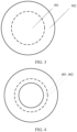
- FIG. 2 is a schematic diagram of a first distribution of erbium ions in a fiber core according to this application. As shown in FIG. 2 , the average doping concentration of erbium ions of the inner layer of the fiber core is a concentration 201.
- the average doping concentration of erbium ions of the outer layer of the fiber core is a concentration 202.
- the concentration 202 is less than the concentration 201. It should be understood that, in an actual processing process, a processing technology cannot guarantee that a concentration of each point in the fiber core is the same. Therefore, the concentration 201 and the concentration 201 may alternatively be a curve that fluctuates up and down. Similarly, in subsequent descriptions, "a doping concentration of erbium ions of the first sublayer is the same" means “the doping concentration of erbium ions of the first sublayer is approximately the same".
- FIG. 3 is a schematic diagram of a first structure of a fiber core according to this application.
- the fiber core includes a first layer 301 and a second layer 302.
- the first layer 301 is alternatively referred to as an inner layer
- the second layer 302 is alternatively referred to as an outer layer.
- the first layer 301 may be a circular.
- the first layer 301 includes a center of the fiber core.
- the second layer is an annulus.
- An outer ring of the annulus is an outer ring of the fiber core.
- An average doping concentration of erbium ions of the first layer 301 is higher than an average doping concentration of erbium ions of the second layer 302.
- a boundary line between the first layer 301 and the second layer 302 may or may not overlap with a boundary line between the two sublayers.
- the two sublayers include a first sublayer and a second sublayer.
- the first layer 301 is the first sublayer
- the second layer 302 is the second sublayer.
- a doping concentration of erbium ions of the first sublayer is the same.
- a doping concentration of erbium ions of the second sublayer is the same. In this case, because the doping concentration of erbium ions of the first sublayer is greater than the doping concentration of erbium ions of the second sublayer, there is a sudden change of the doping concentration of erbium ions at the boundary lines.
- FIG. 4 is a schematic diagram of a second structure of a fiber core according to this application.
- the fiber core includes a first boundary line 401 and a second boundary line 402.
- the first boundary line 401 divides the fiber core into a first sublayer and a second sublayer.
- the first sublayer is within the first boundary line 401, and a doping concentration of erbium ions of the first sublayer is the same.
- the second sublayer is outside the second boundary line 401, and a doping concentration of erbium ions in the second sublayer is the same.
- the doping concentration of erbium ions of the first sublayer is higher than the doping concentration of erbium ions of the second sublayer. Therefore, there is a sudden change of a doping concentration of erbium ions at the first boundary line 401.
- the second boundary line 402 divides the fiber core into a first layer and a second layer.
- the first layer is within the second boundary line 402, and the second layer is outside the second boundary line 402.
- the average doping concentration of erbium ions of the first layer is higher than the average doping concentration of erbium ions of the second layer.
- the doping concentration of erbium ions of the first sublayer is the same, and the second boundary line 402 is within the first sublayer, there is no sudden change of a doping concentration of erbium ions at the second boundary line 402.
- all layer boundary lines overlap with sublayer boundary lines in the fiber core.
- the layer boundary line is a boundary line between "layers”
- the sublayer boundary line is a boundary line between "sublayers”.
- a solid line represents a boundary line or a dividing line at which there is a sudden change of the doping concentration of erbium ions, and two sides of the solid line are different "sublayers".
- sublayer refer to subsequent descriptions of the sublayer in the preparation method for the erbium-doped fiber.
- Two sides of a dotted line are different "layers”.
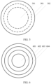
- FIG. 5 is a schematic diagram of a third structure of a fiber core according to this application.
- the fiber core includes a first layer 301 and a second layer 302.
- the first layer 301 includes a center of the fiber core.
- An outer ring of the second layer 302 is an outer ring of the fiber core.
- the average doping concentration of erbium ions of the first layer 301 is higher than the average doping concentration of erbium ions of the second layer 302.
- the fiber core further includes another layer between the first layer and the second layer.
- the fiber core further includes a third layer 501.
- the third layer 501 is between the first layer 301 and the second layer 302.
- An average doping concentration of erbium ions of the third layer 501 is less than the average doping concentration of erbium ions of the first layer 301, and the average doping concentration of erbium ions of the second layer 302 is less than the doping concentration of erbium ions of the third layer 501.
- the “layer” may include one or more "sublayers".
- the first layer includes K sublayers, where K is an integer greater than 0.
- K is an integer greater than 1.
- the second layer includes P sublayers, where P is an integer greater than 0.
- a distribution of light intensity in the fiber core is a Gaussian distribution. The closer the distribution of the erbium ions in the fiber core is to the Gaussian distribution, the more effectively the noise figure of erbium-doped fiber can be reduced.
- this application may limit that along the center of the fiber core from inside to outside, a doping concentration of erbium ions of K+P sublayers gradually decreases to enable the distribution of erbium ions in the fiber core to be close to the Gaussian distribution.
- FIG. 6 is a schematic diagram of a fourth structure of a fiber core according to this application. As shown in FIG.
- the fiber core includes a first sublayer 601, a second sublayer 602, a third sublayer 603, and a fourth sublayer 604.
- the first sublayer 601 and the second sublayer 602 belong to the first layer.
- the third sublayer 603 and the fourth sublayer 604 belong to the second layer.
- Doping concentrations of erbium ions of the first sublayer 601, the second sublayer 602, the third sublayer 603, and the fourth sublayer 604 gradually decrease from inside to outside along the center of the fiber core.
- the erbium-doped fiber in this application is used in an L band.
- a gain coefficient of signal light in the L band is low in the erbium-doped fiber. Therefore, in order to increase the gain of the erbium-doped fiber amplifier, the doping concentration of erbium ions of the erbium-doped fiber needs to be increased.
- the doping concentration of erbium ions of the erbium-doped fiber is usually between 300 ppm and 500 ppm.
- the doping concentration of erbium ions of the erbium-doped fiber should usually be greater than 1500 ppm.
- An outer layer of the erbium-doped fiber contains more erbium ions by increasing the doping concentration of erbium ions in the erbium-doped fiber. More erbium ions produce a larger ASE, and further produce a larger noise figure.
- a noise figure of a C-band erbium-doped fiber amplifier is usually less than 5 dB.
- a noise figure of an L band erbium-doped fiber amplifier is usually greater than 6 dB. Therefore, in the L band, it is important to reduce the doping concentration of erbium ions of the outer layer of the erbium-doped fiber, to reduce the noise figure.
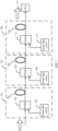
- FIG. 7 is a schematic diagram of a first structure of an optical communications system according to this application.
- the optical communications system includes an optical amplifier 701, an optical amplifier 705, an optical amplifier 709, and an optical spectrum analyzer (optical spectrum analyzer, OSA) 713.
- the optical amplifier 701 includes a pump light source 704, a wavelength division multiplexer (Wavelength Division Multiplexer, WDM) 703, and an erbium-doped fiber 702.
- the pump light source 704 is configured to generate pump light.
- the WDM 703 is configured to couple the signal light and the pump light into the erbium-doped fiber 702.
- the pump light amplifies the signal light.
- the optical amplifier 705 includes a pump light source 708, a wavelength division multiplexer WDM 707, and an erbium-doped fiber 706.
- the optical amplifier 709 includes a pump light source 712, a wavelength division multiplexer WDM 711, and an erbium-doped fiber 710. In the optical communications system in FIG. 7 , a three-stage amplification of the signal light is implemented.
- the OSA 713 is configured to measure a noise figure of the signal light after the three-stage amplification.
- the noise figure of the amplifier is measured by using 0 dBm L-band signal light as an input signal.
- the noise figure of the amplifier may alternatively be referred to as the noise figure of the erbium-doped fiber.
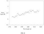
- FIG. 8 is a schematic diagram of a distribution of noise figures of an erbium-doped fiber on different wavelengths. As shown in FIG. 8 , a horizontal coordinate is a wavelength, where a unit is nanometer nm. A vertical coordinate is a noise figure, where a unit is dB. In a range of 1575 nm to 1618 nm, a maximum noise figure of the amplifier is 6.6 dB, and an average noise figure is approximately 6.3 dB.
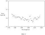
- the optical communications system in FIG. 7 is used to measure the noise figure of the erbium-doped fiber amplifier in this application.
- the schematic diagram of the structure of the erbium-doped fiber is shown in FIG. 3 .
- FIG. 9 is a schematic diagram of a first distribution of noise figures of an erbium-doped fiber according to this application. As shown in FIG. 9 , in a range of 1575 nm to 1618 nm, a maximum noise figure of the erbium-doped fiber amplifier is 5.2 dB, and the average noise figure is less than 5 dB.
- FIG. 10 is a schematic diagram of a second distribution of noise figures of an erbium-doped fiber according to this application. As shown in FIG. 10 , in a range of 1575 nm to 1618 nm, a maximum noise figure of the erbium-doped fiber amplifier is 5.4 dB, and the average noise figure is less than 5.2 dB.
- the average doping concentration of erbium ions of the first layer is defined to be higher than the average doping concentration of erbium ions of the second layer by more than M percent. It can be learned from the foregoing experiments that, when a value of M is between 30 and 75.6, the average noise figure of the erbium-doped fiber amplifier is less than 5.5 dB.
- a cross-sectional area of the first layer is defined to be within N percent of a cross-sectional area of the fiber core. It can be learned from the foregoing experiments that, when a value of N is between 20 and 50, the average noise figure of the erbium-doped fiber amplifier is less than 5.5 dB.
- the average noise figure of the erbium-doped fiber amplifier is less than 5.5 dB.
- an experimental result similar to that in FIG. 9 may be obtained.
- an area of the first sublayer 601 accounts for 19% of the area of the fiber core, and a doping concentration of erbium ions of the first sublayer 601 is 2887 ppm.
- An area of the second sublayer 602 accounts for 26% of the area of the fiber core, and a doping concentration of erbium ions of the second sublayer 602 is 2206 ppm.
- An area of the third sublayer 603 accounts for 27% of the area of the fiber core, and a doping concentration of erbium ions of the third sublayer 603 is 1228 ppm.
- An area of the fourth sublayer 604 accounts for 28% of the area of the fiber core, and a doping concentration of erbium ions of the fourth sublayer 604 is 501 ppm. Because an error may occur during fiber core processing, the error is defined as ⁇ 200 ppm.
- a range of the doping concentration of erbium ions of the first sublayer 601 is between 2687 ppm and 3087 ppm.
- a range of the doping concentration of erbium ions of the second sublayer 602 is between 2006 ppm and 2406 ppm.
- a range of the doping concentration of erbium ions of the third sublayer 603 is between 1028 ppm and 1428 ppm.
- a range of the doping concentration of erbium ions of the fourth sublayer 604 is between 301 ppm and 701 ppm.
- the Gaussian distribution of the erbium ions in the fiber core is implemented by increasing a layer quantity of the sublayers in the fiber core.
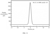
- the doping concentration of erbium ions of the fiber core satisfies the following relationship.
- A is the doping concentration of erbium ions at the center of the fiber core.
- a range of A is between 1500 ppm and 4000 ppm.
- C(r) is a doping concentration of erbium ions at a target point, r is a distance between the target point and the center of the fiber core. r is less than or equal to R.
- R is a radius of the fiber core.
- a range of R is between 0.01 micrometers and 0.3 micrometers.
- ⁇ is a correction factor of a negative value.
- FIG. 11 is a schematic diagram of a second distribution of erbium ions in a fiber core according to this application. As shown in FIG. 11 , when R is equal to 2.5, Ais equal to 3000, and ⁇ is equal to -0.5, the distribution of the erbium ions in the fiber core approaches the Gaussian distribution.
- the foregoing describes the erbium-doped fiber in this application.
- the following describes a preparation method for an erbium-doped fiber in this application.
- the preparation method for an erbium-doped fiber includes the following steps.
- step 1 a loose layer is deposited in a base tube, and the loose layer is immersed in erbium ion solution.
- the base tube is pretreated to preheat the base tube and effectively eliminate impurities and bubbles on an inner wall of the base tube.
- raw materials are fed into the base tube by using an MCVD device.
- the raw materials Under a heating condition of a heat source hydrogen-oxygen torch, the raw materials are chemically reacted to generate fine particles such as silicon dioxide, phosphorus pentoxide, silicon fluoride, and boron trioxide.
- the fine particles Under a thermophoresis effect and gas in the tube, the fine particles are deposited on the inner surface of the base tube.
- a low heating temperature for example, between 1300°C and 1500°C
- a white opaque porous loose layer is formed, where a length between of the loose layer is between 150 mm and 300 mm.
- rare-earth co-doped raw materials are dissolved into solution of alcohol or hydrochloric acid in a specific proportion to obtain mixed solution.
- the mixed solution includes ions such as an erbium ion Er3+, a phosphorus ion P5+, an aluminum ion Al3+, and lanthanum La3+. Therefore, the mixed solution is also referred to as erbium ion solution.
- An obtained loose body is soaked into the prepared mixed solution. In a soaking process, the base tube may be placed in a rotary lathe to enable the base tube to rotate at a speed of 30 rotations/minute. A rare-earth co-doped ion penetrates into the loose layer through surface adsorption.
- step 2 the loose layer is taken out from the erbium ion solution, and the loose layer is dried and vitrified, to obtain a glass rod.
- the erbium ion solution is poured out.
- Preliminary nitrogen drying is performed on the base tube.
- the preliminarily dried base tube may be heated to 800°C to 1000°C, to further remove residual hydroxy ions in the loose layer.
- the loose layer is heated to 1500°C to sinter into a transparent and compact glass rod.
- Gas including P5+ is then introduced for gas phase compensation to improve a doping concentration of P5+.
- the doped elements are fastened to the glass rod to form a non-porous glass layer.
- Step 1 and step 2 are repeated for Z times, and a concentration of erbium ion solution obtained each time is gradually increased, where Z is an integer greater than 1.
- step 3 the glass rod is sintered into a solid glass rod.
- the process of sintering a vitrified glass rod into a solid glass rod at a high temperature is also referred to as collapse.
- step 4 the solid glass rod is prepared into the erbium-doped fiber.
- the solid glass rod is attenuated to the erbium-doped fiber.
- FIG. 12 is a schematic diagram of a structure of an erbium-doped fiber in a preparation process according to this application.
- step 1 the base tube is provided, and a loose body 1 is deposited in the base tube.
- the loose body 1 is immersed in erbium ion solution 1.
- step 2 the loose body 1 is dried and vitrified to obtain a glass rod 1.
- step 1 and step 2 are repeated. Specifically, a loose body 2 is deposited in the glass rod 1.
- the loose body 2 is immersed in erbium ion solution 2.
- a concentration of the erbium ion solution 2 is greater than a concentration of the erbium ion solution 1.
- the loose body 2 is dried and vitrified to obtain a glass rod 2.
- the glass rod 2 is collapsed to obtain a solid glass rod.
- the solid glass rod is prepared into the erbium-doped fiber.
- a quantity of sublayers of a fiber core is Z.
- Z when Z is 2, step 1 and step 2 in the preparation method are performed twice in total.
- two loose layers are obtained through deposition.
- the two loose layers respectively correspond to two sublayers of the fiber core.
- Z when Z is 4, step 1 and step 2 in the preparation method are performed for four times in total.
- four loose layers are obtained through deposition.
- the four loose layers respectively correspond to four sublayers of the fiber core.
- the four loose layers are obtained through deposition.
- the four loose layers are respectively immersed in erbium ion solution 1 of different concentrations.
- the concentrations of the erbium ion solution obtained for four times are respectively Y1, Y2, Y3, and Y4 mol/L.
- a difference between Y2 and Y1 is between 0.001 mol/L and 0.004 mol/L.
- a difference between Y3 and Y2 is between 0.004 mol/L and 0.01 mol/L.
- a difference between Y4 and Y3 is between 0.01 mol/L and 0.016 mol/L.
- FIG. 13 is a schematic diagram of a structure of an EDFA according to this application.
- an EDFA 1301 includes a pump light source 1304, an optical coupler 1303, and an erbium-doped fiber 1302.
- the optical coupler 1303 can be a WDM.
- the pump light source 1304 is configured to generate pump light.
- the optical coupler 1303 is configured to receive signal light and the pump light, and couple the signal light and the pump light into the erbium-doped fiber 1302.
- the erbium-doped fiber 1302 is configured to amplify the signal light under an action of the pump light.
- FIG. 14 is a schematic diagram of a second structure of an optical communications system according to this application.
- the optical communications system includes a transmit end 1401, a receive end 1403, and an EDFA 1402.
- the transmit end 1401 is configured to transmit signal light to the receive end 1403 by using an optical fiber.
- the optical fiber is connected to the EDFA 1402.
- the EDFA 1402 is configured to generate pump light and amplify signal light based on the pump light.
- the receive end 1403 is configured to receive an amplified signal light.
- a plurality of EDFAs 1402 may be connected in series between the transmit end 1401 and the receive end 1403.
- the plurality of EDFAs 1402 is configured to amplify the signal light for a plurality of times.
Landscapes
- Physics & Mathematics (AREA)
- Electromagnetism (AREA)
- Engineering & Computer Science (AREA)
- Plasma & Fusion (AREA)
- Optics & Photonics (AREA)
- Chemical & Material Sciences (AREA)
- Computer Networks & Wireless Communication (AREA)
- Signal Processing (AREA)
- General Life Sciences & Earth Sciences (AREA)
- Geochemistry & Mineralogy (AREA)
- Manufacturing & Machinery (AREA)
- Life Sciences & Earth Sciences (AREA)
- Materials Engineering (AREA)
- Organic Chemistry (AREA)
- Lasers (AREA)
Applications Claiming Priority (2)
| Application Number | Priority Date | Filing Date | Title |
|---|---|---|---|
| CN202110592797.9A CN115411596A (zh) | 2021-05-28 | 2021-05-28 | 掺铒光纤和掺铒光纤的制备方法 |
| PCT/CN2022/080265 WO2022247395A1 (zh) | 2021-05-28 | 2022-03-11 | 掺铒光纤和掺铒光纤的制备方法 |
Publications (2)
| Publication Number | Publication Date |
|---|---|
| EP4336680A1 true EP4336680A1 (de) | 2024-03-13 |
| EP4336680A4 EP4336680A4 (de) | 2024-11-06 |
Family
ID=84154936
Family Applications (1)
| Application Number | Title | Priority Date | Filing Date |
|---|---|---|---|
| EP22810129.1A Pending EP4336680A4 (de) | 2021-05-28 | 2022-03-11 | Erbiumdotierte faser und herstellungsverfahren für erbiumdotierte faser |
Country Status (4)
| Country | Link |
|---|---|
| US (1) | US20240097395A1 (de) |
| EP (1) | EP4336680A4 (de) |
| CN (1) | CN115411596A (de) |
| WO (1) | WO2022247395A1 (de) |
Families Citing this family (1)
| Publication number | Priority date | Publication date | Assignee | Title |
|---|---|---|---|---|
| CN118405842B (zh) * | 2024-06-04 | 2025-03-04 | 武汉长进光子技术股份有限公司 | 一种掺铋光纤及其制备方法 |
Family Cites Families (13)
| Publication number | Priority date | Publication date | Assignee | Title |
|---|---|---|---|---|
| US5027079A (en) * | 1990-01-19 | 1991-06-25 | At&T Bell Laboratories | Erbium-doped fiber amplifier |
| WO2000074184A1 (en) * | 1999-05-28 | 2000-12-07 | Sumitomo Electric Industries, Ltd. | Optical fiber for optical amplification and optical fiber amplifier |
| US7164833B2 (en) * | 2003-09-24 | 2007-01-16 | Fitel U.S.A. Corp. | Optical fiber for improved performance in S-, C- and L-bands |
| US8767286B2 (en) * | 2010-04-12 | 2014-07-01 | Lockheed Martin Corporation | Signal and pump mode-field adaptor for double-clad fibers and associated method |
| CN102086089A (zh) * | 2010-12-27 | 2011-06-08 | 富通集团有限公司 | 一种制造掺稀土光纤预制棒的方法 |
| JP5551631B2 (ja) * | 2011-02-09 | 2014-07-16 | 三菱電線工業株式会社 | 希土類添加光ファイバ及びその製造方法 |
| CN103257394B (zh) * | 2013-04-26 | 2015-01-14 | 中国人民解放军国防科学技术大学 | 用于输出特定单一模式激光的增益光纤 |
| CN103728691B (zh) * | 2013-12-26 | 2015-09-30 | 长春理工大学 | 阶跃高斯复合型掺杂离子浓度分布增益光纤 |
| CN104591535B (zh) * | 2014-11-04 | 2017-11-14 | 华南师范大学 | 采用激光熔炼技术制备稀土掺杂石英玻璃微结构光纤的方法 |
| CN105207046A (zh) * | 2015-10-22 | 2015-12-30 | 南京大学(苏州)高新技术研究院 | 一种提高掺铒光纤放大器抗辐射能力的方法 |
| CN105244741A (zh) * | 2015-11-05 | 2016-01-13 | 长飞光纤光缆股份有限公司 | 一种大模场掺镱光纤 |
| CN108802898B (zh) * | 2018-08-29 | 2023-05-02 | 法尔胜泓昇集团有限公司 | 一种大模场掺镱有源光纤及其制备方法 |
| CN112510472B (zh) * | 2019-09-16 | 2022-08-09 | 华为技术有限公司 | 一种少模掺铒光纤以及少模掺铒光纤放大器 |
-
2021
- 2021-05-28 CN CN202110592797.9A patent/CN115411596A/zh active Pending
-
2022
- 2022-03-11 EP EP22810129.1A patent/EP4336680A4/de active Pending
- 2022-03-11 WO PCT/CN2022/080265 patent/WO2022247395A1/zh not_active Ceased
-
2023
- 2023-11-27 US US18/519,189 patent/US20240097395A1/en active Pending
Also Published As
| Publication number | Publication date |
|---|---|
| EP4336680A4 (de) | 2024-11-06 |
| CN115411596A (zh) | 2022-11-29 |
| US20240097395A1 (en) | 2024-03-21 |
| WO2022247395A1 (zh) | 2022-12-01 |
Similar Documents
| Publication | Publication Date | Title |
|---|---|---|
| EP2338845B1 (de) | Mit seltenen Erden dotierte optische Faser die eine kleine numerische Apertur aufweist | |
| US11407671B2 (en) | Process of fabrication of Erbium and Ytterbium-co-doped multi-elements silica glass based cladding-pumped fiber | |
| EP0490881B1 (de) | Optische Faser mit fluoreszentem Additiv | |
| EP0533324A2 (de) | Sensibilisierte Er-dotierte Glasfaser als optischer Verstärker und Lichtquelle | |
| CN101316800B (zh) | 添加稀土类纤芯光纤及其制造方法 | |
| JP2017059845A (ja) | 利得等化数モード・ファイバ増幅器 | |
| Yang et al. | Gain and laser performance of heavily Er-doped silica fiber fabricated by MCVD combined with the sol-gel method | |
| CN110467342A (zh) | 一种超宽带增益掺铒光纤及其制备方法 | |
| US20240097395A1 (en) | Erbium-doped fiber and preparation method for erbium-doped fiber | |
| CN114180823A (zh) | 抗辐照超宽带L-band掺铒光纤及其制备方法和应用 | |
| Campbell et al. | Toward optimizing gain in Er–Ba nanoparticle-doped optical fibers | |
| Campbell et al. | Characterization of Er–Ba nanoparticle suspension-doped aluminosilicate optical fibers for 1550 nm amplification | |
| Khopin et al. | Doping of optical fiber preforms via porous silica layer infiltration with salt solutions | |
| EP2088650B1 (de) | Verfahren zur lichtverdunkelungs-unterdrückung einer yb-dotierten glasfaser, durch lichtverdunkelung unterdrückte yb-dotierte glasfaser und faser-laser | |
| Kasik et al. | Thulium-doped optical fibers for fiber lasers operating at around 2 μm | |
| EP4300146B1 (de) | Erbium dotierte faser | |
| US6851281B2 (en) | Method of fabricating rare earth doped optical fibre | |
| Li et al. | Optical properties and laser output of heavily Yb-doped fiber prepared by sol-gel method and DC-RTA technique | |
| Zheng et al. | Preparation of Yb3+-doped silica fiber preform at low temperature | |
| EP4625008A1 (de) | Optische faser, verfahren zur herstellung einer optischen faser und faseroptischer verstärker | |
| Kasik et al. | Properties and fabrication of ytterbium-erbium co-doped silica fibres for high-power fibre lasers | |
| Kasik et al. | Silica optical fibers doped with Yb3+ and Er3+ | |
| Zhai | Development of erbium-doped and bismuth-doped optical fibres for wideband and high-performance amplifiers for telecommunication applications | |
| Bhadra et al. | Development of rare-earth doped fibres for amplifiers in WDM systems | |
| Grubb et al. | + 20dBm erbium power amplifier pumped by a diode-pumped Nd: YAG laser |
Legal Events
| Date | Code | Title | Description |
|---|---|---|---|
| STAA | Information on the status of an ep patent application or granted ep patent |
Free format text: STATUS: THE INTERNATIONAL PUBLICATION HAS BEEN MADE |
|
| PUAI | Public reference made under article 153(3) epc to a published international application that has entered the european phase |
Free format text: ORIGINAL CODE: 0009012 |
|
| STAA | Information on the status of an ep patent application or granted ep patent |
Free format text: STATUS: REQUEST FOR EXAMINATION WAS MADE |
|
| 17P | Request for examination filed |
Effective date: 20231206 |
|
| AK | Designated contracting states |
Kind code of ref document: A1 Designated state(s): AL AT BE BG CH CY CZ DE DK EE ES FI FR GB GR HR HU IE IS IT LI LT LU LV MC MK MT NL NO PL PT RO RS SE SI SK SM TR |
|
| DAV | Request for validation of the european patent (deleted) | ||
| DAX | Request for extension of the european patent (deleted) | ||
| A4 | Supplementary search report drawn up and despatched |
Effective date: 20241009 |
|
| RIC1 | Information provided on ipc code assigned before grant |
Ipc: H04B 10/291 20130101ALI20241002BHEP Ipc: H04B 10/2507 20130101ALI20241002BHEP Ipc: H01S 3/16 20060101ALI20241002BHEP Ipc: H01S 3/067 20060101AFI20241002BHEP |
|
| RAP3 | Party data changed (applicant data changed or rights of an application transferred) |
Owner name: HUAWEI TECHNOLOGIES CO., LTD. |