EP4336661A1 - Electrical connection assembly and electrical connection device - Google Patents
Electrical connection assembly and electrical connection device Download PDFInfo
- Publication number
- EP4336661A1 EP4336661A1 EP23195127.8A EP23195127A EP4336661A1 EP 4336661 A1 EP4336661 A1 EP 4336661A1 EP 23195127 A EP23195127 A EP 23195127A EP 4336661 A1 EP4336661 A1 EP 4336661A1
- Authority
- EP
- European Patent Office
- Prior art keywords
- circuit board
- connection
- electrical connection
- adapter circuit
- press fitting
- Prior art date
- Legal status (The legal status is an assumption and is not a legal conclusion. Google has not performed a legal analysis and makes no representation as to the accuracy of the status listed.)
- Pending
Links
Images




Classifications
-
- H—ELECTRICITY
- H01—ELECTRIC ELEMENTS
- H01R—ELECTRICALLY-CONDUCTIVE CONNECTIONS; STRUCTURAL ASSOCIATIONS OF A PLURALITY OF MUTUALLY-INSULATED ELECTRICAL CONNECTING ELEMENTS; COUPLING DEVICES; CURRENT COLLECTORS
- H01R12/00—Structural associations of a plurality of mutually-insulated electrical connecting elements, specially adapted for printed circuits, e.g. printed circuit boards [PCB], flat or ribbon cables, or like generally planar structures, e.g. terminal strips, terminal blocks; Coupling devices specially adapted for printed circuits, flat or ribbon cables, or like generally planar structures; Terminals specially adapted for contact with, or insertion into, printed circuits, flat or ribbon cables, or like generally planar structures
- H01R12/70—Coupling devices
- H01R12/77—Coupling devices for flexible printed circuits, flat or ribbon cables or like structures
- H01R12/79—Coupling devices for flexible printed circuits, flat or ribbon cables or like structures connecting to rigid printed circuits or like structures
-
- H—ELECTRICITY
- H01—ELECTRIC ELEMENTS
- H01R—ELECTRICALLY-CONDUCTIVE CONNECTIONS; STRUCTURAL ASSOCIATIONS OF A PLURALITY OF MUTUALLY-INSULATED ELECTRICAL CONNECTING ELEMENTS; COUPLING DEVICES; CURRENT COLLECTORS
- H01R12/00—Structural associations of a plurality of mutually-insulated electrical connecting elements, specially adapted for printed circuits, e.g. printed circuit boards [PCB], flat or ribbon cables, or like generally planar structures, e.g. terminal strips, terminal blocks; Coupling devices specially adapted for printed circuits, flat or ribbon cables, or like generally planar structures; Terminals specially adapted for contact with, or insertion into, printed circuits, flat or ribbon cables, or like generally planar structures
- H01R12/50—Fixed connections
- H01R12/51—Fixed connections for rigid printed circuits or like structures
- H01R12/52—Fixed connections for rigid printed circuits or like structures connecting to other rigid printed circuits or like structures
-
- H—ELECTRICITY
- H01—ELECTRIC ELEMENTS
- H01R—ELECTRICALLY-CONDUCTIVE CONNECTIONS; STRUCTURAL ASSOCIATIONS OF A PLURALITY OF MUTUALLY-INSULATED ELECTRICAL CONNECTING ELEMENTS; COUPLING DEVICES; CURRENT COLLECTORS
- H01R12/00—Structural associations of a plurality of mutually-insulated electrical connecting elements, specially adapted for printed circuits, e.g. printed circuit boards [PCB], flat or ribbon cables, or like generally planar structures, e.g. terminal strips, terminal blocks; Coupling devices specially adapted for printed circuits, flat or ribbon cables, or like generally planar structures; Terminals specially adapted for contact with, or insertion into, printed circuits, flat or ribbon cables, or like generally planar structures
- H01R12/50—Fixed connections
- H01R12/59—Fixed connections for flexible printed circuits, flat or ribbon cables or like structures
- H01R12/62—Fixed connections for flexible printed circuits, flat or ribbon cables or like structures connecting to rigid printed circuits or like structures
-
- H—ELECTRICITY
- H01—ELECTRIC ELEMENTS
- H01R—ELECTRICALLY-CONDUCTIVE CONNECTIONS; STRUCTURAL ASSOCIATIONS OF A PLURALITY OF MUTUALLY-INSULATED ELECTRICAL CONNECTING ELEMENTS; COUPLING DEVICES; CURRENT COLLECTORS
- H01R12/00—Structural associations of a plurality of mutually-insulated electrical connecting elements, specially adapted for printed circuits, e.g. printed circuit boards [PCB], flat or ribbon cables, or like generally planar structures, e.g. terminal strips, terminal blocks; Coupling devices specially adapted for printed circuits, flat or ribbon cables, or like generally planar structures; Terminals specially adapted for contact with, or insertion into, printed circuits, flat or ribbon cables, or like generally planar structures
- H01R12/50—Fixed connections
- H01R12/51—Fixed connections for rigid printed circuits or like structures
- H01R12/52—Fixed connections for rigid printed circuits or like structures connecting to other rigid printed circuits or like structures
- H01R12/523—Fixed connections for rigid printed circuits or like structures connecting to other rigid printed circuits or like structures by an interconnection through aligned holes in the boards or multilayer board
-
- H—ELECTRICITY
- H01—ELECTRIC ELEMENTS
- H01R—ELECTRICALLY-CONDUCTIVE CONNECTIONS; STRUCTURAL ASSOCIATIONS OF A PLURALITY OF MUTUALLY-INSULATED ELECTRICAL CONNECTING ELEMENTS; COUPLING DEVICES; CURRENT COLLECTORS
- H01R12/00—Structural associations of a plurality of mutually-insulated electrical connecting elements, specially adapted for printed circuits, e.g. printed circuit boards [PCB], flat or ribbon cables, or like generally planar structures, e.g. terminal strips, terminal blocks; Coupling devices specially adapted for printed circuits, flat or ribbon cables, or like generally planar structures; Terminals specially adapted for contact with, or insertion into, printed circuits, flat or ribbon cables, or like generally planar structures
- H01R12/50—Fixed connections
- H01R12/51—Fixed connections for rigid printed circuits or like structures
- H01R12/55—Fixed connections for rigid printed circuits or like structures characterised by the terminals
- H01R12/58—Fixed connections for rigid printed circuits or like structures characterised by the terminals terminals for insertion into holes
- H01R12/585—Terminals having a press fit or a compliant portion and a shank passing through a hole in the printed circuit board
-
- H—ELECTRICITY
- H01—ELECTRIC ELEMENTS
- H01R—ELECTRICALLY-CONDUCTIVE CONNECTIONS; STRUCTURAL ASSOCIATIONS OF A PLURALITY OF MUTUALLY-INSULATED ELECTRICAL CONNECTING ELEMENTS; COUPLING DEVICES; CURRENT COLLECTORS
- H01R12/00—Structural associations of a plurality of mutually-insulated electrical connecting elements, specially adapted for printed circuits, e.g. printed circuit boards [PCB], flat or ribbon cables, or like generally planar structures, e.g. terminal strips, terminal blocks; Coupling devices specially adapted for printed circuits, flat or ribbon cables, or like generally planar structures; Terminals specially adapted for contact with, or insertion into, printed circuits, flat or ribbon cables, or like generally planar structures
- H01R12/70—Coupling devices
- H01R12/7005—Guiding, mounting, polarizing or locking means; Extractors
- H01R12/7011—Locking or fixing a connector to a PCB
- H01R12/7064—Press fitting
-
- H—ELECTRICITY
- H01—ELECTRIC ELEMENTS
- H01R—ELECTRICALLY-CONDUCTIVE CONNECTIONS; STRUCTURAL ASSOCIATIONS OF A PLURALITY OF MUTUALLY-INSULATED ELECTRICAL CONNECTING ELEMENTS; COUPLING DEVICES; CURRENT COLLECTORS
- H01R12/00—Structural associations of a plurality of mutually-insulated electrical connecting elements, specially adapted for printed circuits, e.g. printed circuit boards [PCB], flat or ribbon cables, or like generally planar structures, e.g. terminal strips, terminal blocks; Coupling devices specially adapted for printed circuits, flat or ribbon cables, or like generally planar structures; Terminals specially adapted for contact with, or insertion into, printed circuits, flat or ribbon cables, or like generally planar structures
- H01R12/70—Coupling devices
- H01R12/7005—Guiding, mounting, polarizing or locking means; Extractors
- H01R12/7011—Locking or fixing a connector to a PCB
- H01R12/707—Soldering or welding
-
- H—ELECTRICITY
- H01—ELECTRIC ELEMENTS
- H01R—ELECTRICALLY-CONDUCTIVE CONNECTIONS; STRUCTURAL ASSOCIATIONS OF A PLURALITY OF MUTUALLY-INSULATED ELECTRICAL CONNECTING ELEMENTS; COUPLING DEVICES; CURRENT COLLECTORS
- H01R12/00—Structural associations of a plurality of mutually-insulated electrical connecting elements, specially adapted for printed circuits, e.g. printed circuit boards [PCB], flat or ribbon cables, or like generally planar structures, e.g. terminal strips, terminal blocks; Coupling devices specially adapted for printed circuits, flat or ribbon cables, or like generally planar structures; Terminals specially adapted for contact with, or insertion into, printed circuits, flat or ribbon cables, or like generally planar structures
- H01R12/70—Coupling devices
- H01R12/71—Coupling devices for rigid printing circuits or like structures
- H01R12/712—Coupling devices for rigid printing circuits or like structures co-operating with the surface of the printed circuit or with a coupling device exclusively provided on the surface of the printed circuit
- H01R12/716—Coupling device provided on the PCB
-
- H—ELECTRICITY
- H01—ELECTRIC ELEMENTS
- H01R—ELECTRICALLY-CONDUCTIVE CONNECTIONS; STRUCTURAL ASSOCIATIONS OF A PLURALITY OF MUTUALLY-INSULATED ELECTRICAL CONNECTING ELEMENTS; COUPLING DEVICES; CURRENT COLLECTORS
- H01R12/00—Structural associations of a plurality of mutually-insulated electrical connecting elements, specially adapted for printed circuits, e.g. printed circuit boards [PCB], flat or ribbon cables, or like generally planar structures, e.g. terminal strips, terminal blocks; Coupling devices specially adapted for printed circuits, flat or ribbon cables, or like generally planar structures; Terminals specially adapted for contact with, or insertion into, printed circuits, flat or ribbon cables, or like generally planar structures
- H01R12/70—Coupling devices
- H01R12/71—Coupling devices for rigid printing circuits or like structures
- H01R12/72—Coupling devices for rigid printing circuits or like structures coupling with the edge of the rigid printed circuits or like structures
- H01R12/722—Coupling devices for rigid printing circuits or like structures coupling with the edge of the rigid printed circuits or like structures coupling devices mounted on the edge of the printed circuits
- H01R12/727—Coupling devices presenting arrays of contacts
-
- H—ELECTRICITY
- H01—ELECTRIC ELEMENTS
- H01R—ELECTRICALLY-CONDUCTIVE CONNECTIONS; STRUCTURAL ASSOCIATIONS OF A PLURALITY OF MUTUALLY-INSULATED ELECTRICAL CONNECTING ELEMENTS; COUPLING DEVICES; CURRENT COLLECTORS
- H01R12/00—Structural associations of a plurality of mutually-insulated electrical connecting elements, specially adapted for printed circuits, e.g. printed circuit boards [PCB], flat or ribbon cables, or like generally planar structures, e.g. terminal strips, terminal blocks; Coupling devices specially adapted for printed circuits, flat or ribbon cables, or like generally planar structures; Terminals specially adapted for contact with, or insertion into, printed circuits, flat or ribbon cables, or like generally planar structures
- H01R12/70—Coupling devices
- H01R12/71—Coupling devices for rigid printing circuits or like structures
- H01R12/72—Coupling devices for rigid printing circuits or like structures coupling with the edge of the rigid printed circuits or like structures
- H01R12/73—Coupling devices for rigid printing circuits or like structures coupling with the edge of the rigid printed circuits or like structures connecting to other rigid printed circuits or like structures
- H01R12/732—Printed circuits being in the same plane
-
- H—ELECTRICITY
- H01—ELECTRIC ELEMENTS
- H01R—ELECTRICALLY-CONDUCTIVE CONNECTIONS; STRUCTURAL ASSOCIATIONS OF A PLURALITY OF MUTUALLY-INSULATED ELECTRICAL CONNECTING ELEMENTS; COUPLING DEVICES; CURRENT COLLECTORS
- H01R13/00—Details of coupling devices of the kinds covered by groups H01R12/70 or H01R24/00 - H01R33/00
- H01R13/02—Contact members
- H01R13/22—Contacts for co-operating by abutting
-
- H—ELECTRICITY
- H05—ELECTRIC TECHNIQUES NOT OTHERWISE PROVIDED FOR
- H05K—PRINTED CIRCUITS; CASINGS OR CONSTRUCTIONAL DETAILS OF ELECTRIC APPARATUS; MANUFACTURE OF ASSEMBLAGES OF ELECTRICAL COMPONENTS
- H05K1/00—Printed circuits
- H05K1/02—Details
- H05K1/14—Structural association of two or more printed circuits
- H05K1/141—One or more single auxiliary printed circuits mounted on a main printed circuit, e.g. modules, adapters
-
- H—ELECTRICITY
- H01—ELECTRIC ELEMENTS
- H01R—ELECTRICALLY-CONDUCTIVE CONNECTIONS; STRUCTURAL ASSOCIATIONS OF A PLURALITY OF MUTUALLY-INSULATED ELECTRICAL CONNECTING ELEMENTS; COUPLING DEVICES; CURRENT COLLECTORS
- H01R12/00—Structural associations of a plurality of mutually-insulated electrical connecting elements, specially adapted for printed circuits, e.g. printed circuit boards [PCB], flat or ribbon cables, or like generally planar structures, e.g. terminal strips, terminal blocks; Coupling devices specially adapted for printed circuits, flat or ribbon cables, or like generally planar structures; Terminals specially adapted for contact with, or insertion into, printed circuits, flat or ribbon cables, or like generally planar structures
- H01R12/50—Fixed connections
- H01R12/59—Fixed connections for flexible printed circuits, flat or ribbon cables or like structures
- H01R12/65—Fixed connections for flexible printed circuits, flat or ribbon cables or like structures characterised by the terminal
-
- H—ELECTRICITY
- H01—ELECTRIC ELEMENTS
- H01R—ELECTRICALLY-CONDUCTIVE CONNECTIONS; STRUCTURAL ASSOCIATIONS OF A PLURALITY OF MUTUALLY-INSULATED ELECTRICAL CONNECTING ELEMENTS; COUPLING DEVICES; CURRENT COLLECTORS
- H01R12/00—Structural associations of a plurality of mutually-insulated electrical connecting elements, specially adapted for printed circuits, e.g. printed circuit boards [PCB], flat or ribbon cables, or like generally planar structures, e.g. terminal strips, terminal blocks; Coupling devices specially adapted for printed circuits, flat or ribbon cables, or like generally planar structures; Terminals specially adapted for contact with, or insertion into, printed circuits, flat or ribbon cables, or like generally planar structures
- H01R12/70—Coupling devices
- H01R12/7005—Guiding, mounting, polarizing or locking means; Extractors
- H01R12/7011—Locking or fixing a connector to a PCB
- H01R12/7052—Locking or fixing a connector to a PCB characterised by the locating members
Definitions
- the present invention relates to an electrical connection assembly and an electrical connection device comprising the electrical connection assembly.
- the present invention has been made to overcome or alleviate at least one aspect of the above mentioned disadvantages.
- an electrical connection assembly comprises of a first insulator; a first connection terminal which is fixed to the first insulator and includes a first press fitting part and a second press fitting part protruding from the first insulator; a first adapter circuit board, on which a first hole is formed; and a flexible connection member including a connection conductor electrically connected to the first adapter circuit board.
- the first press fitting part is pressed into the first hole of the first adapter circuit board to be electrically connected to the first adapter circuit board; the second press fitting part is adapted to be pressed into a second hole of a first circuit board to be electrically connected to the first circuit board.
- the flexible connection member is a flexible flat cable or a flexible printed circuit board.
- the first insulator comprises of a first body part; and a first slot formed on the first body part.
- the first connection terminal is installed in the first slot, and the first press fitting part and the second press fitting part protrude from the first slot.
- the first connection terminal further comprises of a first connection body which is at least partially accommodated in the first slot; and a first fixing part which is connected to one end of the first connection body and fixed in the first slot.
- One of the first press fitting part and the second press fitting part is connected to the first fixing part, and the other is connected to the other end of the first connection body.
- the first press fitting part and the second press fitting part are respectively located at both ends of the first connection terminal.
- a first positioning hole is formed in the first adapter circuit board; the first insulator further comprises of a first positioning post protruding from the top surface of the first body part for insertion into a first positioning hole of the first adapter circuit board; and/or a second positioning post protruding from the bottom surface of the first body part for insertion into a second positioning hole of the first circuit board.
- the first insulator is an injection molded part formed on the first connection terminal, so that the first insulator and the first connection terminal are formed into an integral piece.
- the electrical connection assembly comprises at least one row of first connection terminals and one flexible connection member, wherein the flexible connection member comprises a row of connection conductors; one ends of a row of connection conductors of the flexible connection member are electrically connected to the first adapter circuit board to be electrically connected to at least one row of first connection terminals via the first adapter circuit board.
- the electrical connection assembly includes at least one row of first connection terminals and multiple flexible connection members stacked up and down, each of the flexible connection members includes a row of connection conductors; one ends of the connection conductors of the multiple flexible connection members are electrically connected to the first adapter circuit board to be electrically connected to at least one row of first connection terminals via the first adapter circuit board.
- the electrical connection assembly further comprises of: a second insulator; a second connection terminal which is fixed to the second insulator and includes a third press fitting part and a fourth press fitting part protruding from the second insulator; and a second adapter circuit board which is formed with a third hole.
- the connection conductor of the flexible connection member is electrically connected to the second adapter circuit board; the third press fitting part is pressed into the third hole of the second adapter circuit board to be electrically connected to the second adapter circuit board; the fourth press fitting part is adapted to be pressed into a fourth hole of a second circuit board to be electrically connected to the second circuit board.
- the electrical connection assembly includes at least one row of second connection terminals and one flexible connection member, the flexible connection member comprises a row of connection conductors; the other ends of a row of connection conductors of the flexible connection member are electrically connected to the second adapter circuit board to be electrically connected to at least one row of second connection terminals via the second adapter circuit board.
- the electrical connection assembly includes at least one row of second connection terminals and multiple flexible connection members stacked up and down, each of the flexible connection members includes a row of connection conductors; the other ends of the connection conductors of the multiple flexible connection members are electrically connected to the second adapter circuit board to be electrically connected to at least one row of second connection terminals via the second adapter circuit board.
- the electrical connection assembly includes two flexible connection members stacked up and down, one ends of the connection conductors of the two flexible connection members are respectively welded to the top and bottom surfaces of the first adapter circuit board, and the other ends are respectively welded to the top and bottom surfaces of the second adapter circuit board.
- the first press fitting part and the second press fitting part of the first connection terminal and/or the third press fitting part and the fourth press fitting part of the second connection terminal are in a fisheye shape.
- the second insulator is identical to the first insulator, enabling the second insulator and the first insulator to be interchangeably used;
- the second connection terminal is identical to the first connection terminal, enabling the second connection terminal and the first connection terminal to be interchangeably used;
- the second adapter circuit board is identical to the first adapter circuit board, enabling the second adapter circuit board and the first adapter circuit board to be interchangeably used.
- connection conductor of the flexible connection member is adapted to be directly and electrically connected to a second circuit board.
- an electrical connection device comprises of: the above electrical connection assembly; and a first circuit board formed with a second hole. The second press fitting part of the first connection terminal of the electrical connection assembly is pressed into the second hole of the first circuit board.
- the electrical connection device further comprises a second circuit board formed with a fourth hole, the fourth press fitting part of the second connection terminal of the electrical connection assembly is pressed into the fourth hole of the second circuit board.
- the electrical connection device further comprises a second circuit board, the connection conductor of the flexible connection member is directly and electrically connected to the second circuit board.
- the electrical connection assembly can achieve flexible electrical connection between two circuit boards, and the electrical connection assembly has a simple structure and low cost.
- an electrical connection assembly comprises of a first insulator; a first connection terminal which is fixed to the first insulator and includes a first press fitting part and a second press fitting part protruding from the first insulator; a first adapter circuit board, on which a first hole is formed; and a flexible connection member including a connection conductor electrically connected to the first adapter circuit board.
- the first press fitting part is pressed into the first hole of the first adapter circuit board to be electrically connected to the first adapter circuit board; the second press fitting part is adapted to be pressed into a second hole of a first circuit board to be electrically connected to the first circuit board.
- an electrical connection device comprises of the above electrical connection assembly; and a first circuit board formed with a second hole. The second press fitting part of the first connection terminal of the electrical connection assembly is pressed into the second hole of the first circuit board.
- Figure 1 shows an illustrative perspective view of an electrical connection device according to an exemplary embodiment of the present invention when viewed from the top
- Figure 2 shows an illustrative exploded view of the electrical connection device according to an exemplary embodiment of the present invention when viewed from the top
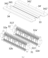
- Figure 3 shows an illustrative exploded view of the electrical connection assembly 3 according to an exemplary embodiment of the present invention when viewed from the top
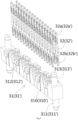
- Figure 4 shows an illustrative exploded view of the insulators 31, 31'and connection terminals 32, 32' of the electrical connection assembly 3 according to an exemplary embodiment of the present invention
- Figure 5 shows an illustrative perspective view of the connection terminals 32, 32'of the electrical connection assembly 3 according to an exemplary embodiment of the present invention.
- an electrical connection device in an exemplary embodiment of the present invention, includes a first circuit board 1, a second circuit board 2, and an electrical connection assembly 3.
- the electrical connection assembly 3 is electrically connected to the first circuit board 1 and the second circuit board 2.
- an electrical connection assembly 3 is disclosed.
- the electrical connection assembly 3 includes a first insulator 31, a first connection terminal 32, a flexible connection member 33, and a first adapter circuit board 34.
- the first connection terminal 32 is fixed to the first insulator 31 and includes a first press fitting part 32a and a second press fitting part 32b extending from the first insulator 31.
- a first hole 341 is formed in the first adapter circuit board 34.
- the flexible connection member 33 includes a connection conductor (not shown) electrically connected to the first adapter circuit board 34.
- the first press fitting part 32a is pressed into the first hole 341 of the first adapter circuit board 34 and electrically connected to the first adapter circuit board 34.
- the second press fitting part 32b is adapted to be pressed into the second hole 101 of the first circuit board 1 to be electrically connected to the first circuit board 1.
- Pressure fitting belongs to welding free connection, therefore, compared to welding, pressure fitting operation has the advantages of simplicity and speed.
- the flexible connection member 33 can be a flexible flat cable (FFC) or a flexible printed circuit board (FPC).
- FFC flexible flat cable
- FPC flexible printed circuit board
- the first insulator 31 includes a first body part 310 and a first slot 312.
- the first slot 312 is formed on the first body part 310.
- the first connection terminal 32 is installed in the first slot 312, and the first press fitting part 32a and the second press fitting part 32b protrude from the first slot 312.
- the first connection terminal 32 further includes a first connection body 320 and a first fixing part 322.
- the first connection body 320 is at least partially accommodated in the first slot 312.
- the first fixing part 322 is connected to one end of the first connection body 320 and is fixed in the first slot 312.
- One of the first press fitting part 32a and the second press fitting part 32b is connected to the first fixing part 322, and the other is connected to the other end of the first connection body 320.
- the first connection terminal 32 extends vertically, with the first press fitting part 32a and the second press fitting part 32b located at the upper and lower ends of the first connection terminal 32, respectively.
- a first positioning hole 342 is formed in the first adapter circuit board 34.
- the first insulator 31 also includes: a first positioning post 313 and a second positioning post 311.
- the first positioning post 313 is formed on the top surface of the first main body part 310 for insertion into the first positioning hole 342 of the first adapter circuit board 34.
- the second positioning post 311 is formed on the bottom surface of the first body part 310 for insertion into the second positioning hole 102 of the first circuit board 1.
- the first connection terminal 32 is an integral stamped terminal.
- the first insulator 31 and the first connection terminal 32 are two independent components separated from each other, and the first connection terminal 32 is installed in the first slot 312 on the first insulator 31.
- the present invention is not limited to the illustrated embodiments, for example, the first insulator 31 can be an injection molded part formed on the first connection terminal 32, so that the first insulator 31 and the first connection terminal 32 are formed into an integral piece.
- the electrical connection assembly includes at least one row of first connection terminals 32 and one flexible connection member 33, and the one flexible connection member 33 includes a row of connection conductors.
- One ends of a row of connection conductors of the flexible connection member 33 are electrically connected to the first adapter circuit board 34 to be electrically connected to at least one row of first connection terminals 32 via the first adapter circuit board 34.
- the electrical connection assembly 3 further includes a second insulator 31', a second connection terminal 32', and a second adapter circuit board 34'.
- the second connection terminal 32' is fixed to the second insulator 31' and includes a third press fitting part 32a' and a fourth press fitting part 32b' protruding from the second insulator 31'.
- a third hole 341' is formed in the second adapter circuit board 34'.
- the connection conductor of the flexible connection member 33 is electrically connected to the second adapter circuit board 34'.
- the third press fitting part 32a' is pressed into the third hole 341' of the second adapter circuit board 34' to be electrically connected to the second adapter circuit board 34'.
- the fourth press fitting part 32b' is adapted to be pressed into a fourth hole 201 of a second circuit board 2 to be electrically connected to the second circuit board 2.
- the electrical connection assembly 3 includes at least one row of second connection terminals 32' and one flexible connection member 33, and the one flexible connection member 33 includes a row of connection conductors.
- the other ends of a row of connection conductors of the flexible connection member 33 are electrically connected to the second adapter circuit board 34' to be electrically connected to at least one row of second connection terminals 32' via the second adapter circuit board 34'.
- the first press fitting part 32a and the second press fitting part 32b of the first connection terminal 32 are in a fisheye shape.
- the third press fitting part 32a' and the fourth press fitting part 32b' of the second connection terminal 32' are in a fisheye shape.
- the second insulator 31' is identical to the first insulator 31, allowing for the interchangeable use of the second insulator 31' and the first insulator 31.
- the second connection terminal 32' is identical to the first connection terminal 32, allowing the second connection terminal 32' and the first connection terminal 32 to be interchangeable.
- the second adapter circuit board 34' is identical to the first adapter circuit board 34, allowing for the interchangeable use of the second adapter circuit board 34' and the first adapter circuit board 34.
- the second insulator 31' includes a second body part 310' and a third slot 312'.
- the third slot 312' is formed on the second body part 310'.
- the second connection terminal 32' is installed in the third slot 312', and the third press fitting part 32a'and the fourth press fitting part 32b' protrude from the third slot 312'.
- the second connection terminal 32' further includes a second connection body 320' and a second fixing part 322'.
- the second connection body 320' is accommodated in the third slot 312'.
- the second fixing part 322' is connected to one end of the second connection body 320' and is fixed in the third slot 312'.
- One of the third press fitting part 32a' and the fourth press fitting part 32b' is connected to the second fixing part 322', and the other is connected to the other end of the second connection body 320'.
- the second connection terminal 32' extends vertically, and the third press fitting part 32a' and the fourth press fitting part 32b' are respectively located at the upper and lower ends of the second connection terminal 32'.
- a third positioning hole 342' is formed in the second adapter circuit board 34'.
- the second insulator 31' also includes a third positioning post 313' and a fourth positioning post 311'.
- the third positioning post 313' protrudes from the top surface of the second body part 310' and is used for inserting into the third positioning hole 342' of the second adapter circuit board 34'.
- the fourth positioning post 311' protrudes from the bottom surface of the second body part 310' and is used for inserting into the fourth positioning hole 202 of the second circuit board 2.
- the second connection terminal 32' is an integral stamped terminal.
- the second insulator 31' and the second connection terminal 32' are two independent components separated from each other, and the second connection terminal 32' is installed in the third slot 312' on the second insulator 31'.
- the present invention is not limited to the illustrated embodiments, for example, the second insulator 31' can be an injection molded part formed on the second insulator 31', so that the second insulator 31' and the second connection terminal 32' are formed into an integral piece.
- an electrical connection device is also disclosed.
- the electrical connection device includes: the aforementioned electrical connection assembly 3 and a first circuit board 1.
- a second hole 101 is formed in the first circuit board 1.
- the second press fitting part 32b of the first connection terminal 32 of the electrical connection assembly 3 is pressed into the second hole 101 of the first circuit board 1.
- the electrical connection device 3 also includes a second circuit board 2.
- a fourth hole 201 is formed in the second circuit board 2.
- the fourth press fitting part 32b' of the second connection terminal 32' of the electrical connection assembly 3 is pressed into the fourth hole 201 of the second circuit board 2.
- connection conductor of the flexible connection member 33 can be welded to the first and second adapter circuit boards 34' respectively, to be electrically connected to the first and second adapter circuit boards 34'.
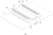
- Figure 6 shows an illustrative perspective view of an electrical connection device according to another exemplary embodiment of the present invention when viewed from the top.
- the electrical connection assembly 3 only includes one flexible connection member 33.
- the electrical connection assembly 3 includes multiple flexible connection members 33 stacked up and down, each of which includes a row of connection conductors.
- One ends of the connection conductors of multiple flexible connection members 33 are electrically connected to the first adapter circuit board 34 to be electrically connected to at least one row of first connection terminals 32 via the first adapter circuit board 34.
- the other ends of the connection conductors of multiple flexible connection members 33 are electrically connected to the second adapter circuit board 34' to be electrically connected to at least one row of second connection terminals 32' via the second adapter circuit board 34'.
- the electrical connection assembly 3 includes two flexible connection members 33 stacked up and down. One ends of the connection conductors of the two flexible connection members 33 are respectively welded to the top and bottom surfaces of the first adapter circuit board 34, and the other ends are welded to the top and bottom surfaces of the second adapter circuit board 34', respectively.
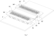
- Figure 7 shows an illustrative perspective view of an electrical connection device according to another exemplary embodiment of the present invention when viewed from the top.
- the main difference between the electrical connection device shown in Figure 7 and the electrical connection device shown in Figure 6 is the number of first connection terminals 32 and second connection terminals 32'.
- the electrical connection assembly 3 includes two rows of first connection terminals 32 and two rows of second connection terminals 32'.
- the electrical connection assembly 3 includes four rows of first connection terminals 32 and four rows of second connection terminals 32'.
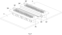
- Figure 8 shows an illustrative perspective view of an electrical connection device according to another exemplary embodiment of the present invention when viewed from the top.
- the main difference between the electrical connection device shown in Figure 8 and the electrical connection device shown in Figure 7 is the number of flexible connection members 33.
- the electrical connection assembly 3 includes two flexible connection members 33 stacked up and down.
- the electrical connection assembly 3 only includes one flexible connection member 33.
- Figure 9 shows an illustrative perspective view of an electrical connection device according to another exemplary embodiment of the present invention when viewed from the top.
- the main difference between the electrical connection device shown in Figure 9 and the electrical connection device shown in Figures 1-5 is the removal of the second insulator 31', the second connection terminal 32', and the second adapter circuit board 34'.
- the other end of the connection conductor of the flexible connection member 33 is directly electrically connected to the second circuit board 2.
- the electrical connection assembly 3 shown in Figure 9 can omit the second insulator 31', the second connection terminal 32', and the second adapter circuit board 34'.
Landscapes
- Engineering & Computer Science (AREA)
- Microelectronics & Electronic Packaging (AREA)
- Coupling Device And Connection With Printed Circuit (AREA)
Abstract
Description
- This application claims the benefit of Chinese Patent Application No.
CN202211082509.6 filed on September 6, 2022 - The present invention relates to an electrical connection assembly and an electrical connection device comprising the electrical connection assembly.
- In the prior art, there are usually two solutions for the electrical connection between circuit boards. One solution is typically to connect the circuit boards by connectors, such as a board end connector on the circuit board and a cable end connector on the cable. The board end connector is mated with the cable end connector. However, this solution requires the provision of two board end connectors and two cable end connectors, resulting in higher costs. The other solution is to electrically connect two circuit boards using a flexible flat cable (FFC) or flexible printed circuit board (FPC), which is directly soldered to the circuit board. However, the welding of flexible flat cable (FFC) or flexible printed circuit board (FPC) is relatively difficult.
- The present invention has been made to overcome or alleviate at least one aspect of the above mentioned disadvantages.
- According to an aspect of the present invention, there is provided an electrical connection assembly. The electrical connection assembly comprises of a first insulator; a first connection terminal which is fixed to the first insulator and includes a first press fitting part and a second press fitting part protruding from the first insulator; a first adapter circuit board, on which a first hole is formed; and a flexible connection member including a connection conductor electrically connected to the first adapter circuit board. The first press fitting part is pressed into the first hole of the first adapter circuit board to be electrically connected to the first adapter circuit board; the second press fitting part is adapted to be pressed into a second hole of a first circuit board to be electrically connected to the first circuit board.
- According to an exemplary embodiment of the present invention, the flexible connection member is a flexible flat cable or a flexible printed circuit board.
- According to another exemplary embodiment of the present invention, the first insulator comprises of a first body part; and a first slot formed on the first body part. The first connection terminal is installed in the first slot, and the first press fitting part and the second press fitting part protrude from the first slot.
- According to another exemplary embodiment of the present invention, the first connection terminal further comprises of a first connection body which is at least partially accommodated in the first slot; and a first fixing part which is connected to one end of the first connection body and fixed in the first slot. One of the first press fitting part and the second press fitting part is connected to the first fixing part, and the other is connected to the other end of the first connection body.
- According to another exemplary embodiment of the present invention, the first press fitting part and the second press fitting part are respectively located at both ends of the first connection terminal.
- According to another exemplary embodiment of the present invention, a first positioning hole is formed in the first adapter circuit board; the first insulator further comprises of a first positioning post protruding from the top surface of the first body part for insertion into a first positioning hole of the first adapter circuit board; and/or a second positioning post protruding from the bottom surface of the first body part for insertion into a second positioning hole of the first circuit board.
- According to another exemplary embodiment of the present invention, the first insulator is an injection molded part formed on the first connection terminal, so that the first insulator and the first connection terminal are formed into an integral piece.
- According to another exemplary embodiment of the present invention, the electrical connection assembly comprises at least one row of first connection terminals and one flexible connection member, wherein the flexible connection member comprises a row of connection conductors; one ends of a row of connection conductors of the flexible connection member are electrically connected to the first adapter circuit board to be electrically connected to at least one row of first connection terminals via the first adapter circuit board.
- According to another exemplary embodiment of the present invention, the electrical connection assembly includes at least one row of first connection terminals and multiple flexible connection members stacked up and down, each of the flexible connection members includes a row of connection conductors; one ends of the connection conductors of the multiple flexible connection members are electrically connected to the first adapter circuit board to be electrically connected to at least one row of first connection terminals via the first adapter circuit board.
- According to another exemplary embodiment of the present invention, the electrical connection assembly further comprises of: a second insulator; a second connection terminal which is fixed to the second insulator and includes a third press fitting part and a fourth press fitting part protruding from the second insulator; and a second adapter circuit board which is formed with a third hole. The connection conductor of the flexible connection member is electrically connected to the second adapter circuit board; the third press fitting part is pressed into the third hole of the second adapter circuit board to be electrically connected to the second adapter circuit board; the fourth press fitting part is adapted to be pressed into a fourth hole of a second circuit board to be electrically connected to the second circuit board.
- According to another exemplary embodiment of the present invention, the electrical connection assembly includes at least one row of second connection terminals and one flexible connection member, the flexible connection member comprises a row of connection conductors; the other ends of a row of connection conductors of the flexible connection member are electrically connected to the second adapter circuit board to be electrically connected to at least one row of second connection terminals via the second adapter circuit board.
- According to another exemplary embodiment of the present invention, the electrical connection assembly includes at least one row of second connection terminals and multiple flexible connection members stacked up and down, each of the flexible connection members includes a row of connection conductors; the other ends of the connection conductors of the multiple flexible connection members are electrically connected to the second adapter circuit board to be electrically connected to at least one row of second connection terminals via the second adapter circuit board.
- According to another exemplary embodiment of the present invention, the electrical connection assembly includes two flexible connection members stacked up and down, one ends of the connection conductors of the two flexible connection members are respectively welded to the top and bottom surfaces of the first adapter circuit board, and the other ends are respectively welded to the top and bottom surfaces of the second adapter circuit board.
- According to another exemplary embodiment of the present invention, the first press fitting part and the second press fitting part of the first connection terminal and/or the third press fitting part and the fourth press fitting part of the second connection terminal are in a fisheye shape.
- According to another exemplary embodiment of the present invention, the second insulator is identical to the first insulator, enabling the second insulator and the first insulator to be interchangeably used; the second connection terminal is identical to the first connection terminal, enabling the second connection terminal and the first connection terminal to be interchangeably used; and the second adapter circuit board is identical to the first adapter circuit board, enabling the second adapter circuit board and the first adapter circuit board to be interchangeably used.
- According to another exemplary embodiment of the present invention, the other end of the connection conductor of the flexible connection member is adapted to be directly and electrically connected to a second circuit board.
- According to another aspect of the present invention, there is provided an electrical connection device. The electrical connection device comprises of: the above electrical connection assembly; and a first circuit board formed with a second hole. The second press fitting part of the first connection terminal of the electrical connection assembly is pressed into the second hole of the first circuit board.
- According to an exemplary embodiment of the present invention, the electrical connection device further comprises a second circuit board formed with a fourth hole, the fourth press fitting part of the second connection terminal of the electrical connection assembly is pressed into the fourth hole of the second circuit board.
- According to another exemplary embodiment of the present invention, the electrical connection device further comprises a second circuit board, the connection conductor of the flexible connection member is directly and electrically connected to the second circuit board.
- In the aforementioned exemplary embodiments of the present invention, the electrical connection assembly can achieve flexible electrical connection between two circuit boards, and the electrical connection assembly has a simple structure and low cost.
- The above and other features of the present invention will become more apparent by describing in detail exemplary embodiments thereof with reference to the accompanying drawings, in which:
-
Figure 1 shows an illustrative perspective view of an electrical connection device according to an exemplary embodiment of the present invention when viewed from the top; -
Figure 2 shows an illustrative exploded view of an electrical connection device according to an exemplary embodiment of the present invention when viewed from the top; -
Figure 3 shows an illustrative exploded view of an electrical connection assembly according to an exemplary embodiment of the present invention when viewed from the top; -
Figure 4 shows an illustrative exploded view of an insulator and connection terminal of an electrical connection assembly according to an exemplary embodiment of the present invention; -
Figure 5 shows an illustrative perspective view of a connection terminal of an electrical connection assembly according to an exemplary embodiment of the present invention; -
Figure 6 shows an illustrative perspective view of an electrical connection device according to another exemplary embodiment of the present invention when viewed from the top; -
Figure 7 shows an illustrative perspective view of an electrical connection device according to another exemplary embodiment of the present invention when viewed from the top; -
Figure 8 shows an illustrative perspective view of an electrical connection device according to another exemplary embodiment of the present invention when viewed from the top; and -
Figure 9 shows an illustrative perspective view of an electrical connection device according to another exemplary embodiment of the present invention when viewed from the top. - Exemplary embodiments of the present disclosure will be described hereinafter in detail with reference to the attached drawings, wherein the like reference numerals refer to the like elements. The present disclosure may, however, be embodied in many different forms and should not be construed as being limited to the embodiment set forth herein; rather, these embodiments are provided so that the present disclosure will be thorough and complete, and will fully convey the concept of the disclosure to those skilled in the art.
- In the following detailed description, for purposes of explanation, numerous specific details are set forth in order to provide a thorough understanding of the disclosed embodiments. It will be apparent, however, that one or more embodiments may be practiced without these specific details. In other instances, well-known structures and devices are schematically shown in order to simplify the drawing.
- According to a general concept of the present invention, there is provided an electrical connection assembly. The electrical connection assembly comprises of a first insulator; a first connection terminal which is fixed to the first insulator and includes a first press fitting part and a second press fitting part protruding from the first insulator; a first adapter circuit board, on which a first hole is formed; and a flexible connection member including a connection conductor electrically connected to the first adapter circuit board. The first press fitting part is pressed into the first hole of the first adapter circuit board to be electrically connected to the first adapter circuit board; the second press fitting part is adapted to be pressed into a second hole of a first circuit board to be electrically connected to the first circuit board.
- According to another general concept of the present invention, there is provided an electrical connection device. The electrical connection device comprises of the above electrical connection assembly; and a first circuit board formed with a second hole. The second press fitting part of the first connection terminal of the electrical connection assembly is pressed into the second hole of the first circuit board.
-
Figure 1 shows an illustrative perspective view of an electrical connection device according to an exemplary embodiment of the present invention when viewed from the top;Figure 2 shows an illustrative exploded view of the electrical connection device according to an exemplary embodiment of the present invention when viewed from the top;Figure 3 shows an illustrative exploded view of theelectrical connection assembly 3 according to an exemplary embodiment of the present invention when viewed from the top;Figure 4 shows an illustrative exploded view of theinsulators 31, 31'andconnection terminals 32, 32' of theelectrical connection assembly 3 according to an exemplary embodiment of the present invention;Figure 5 shows an illustrative perspective view of theconnection terminals 32, 32'of theelectrical connection assembly 3 according to an exemplary embodiment of the present invention. - As shown in
Figures 1 to 5 , in an exemplary embodiment of the present invention, an electrical connection device is disclosed. The electrical connection device includes afirst circuit board 1, asecond circuit board 2, and anelectrical connection assembly 3. Theelectrical connection assembly 3 is electrically connected to thefirst circuit board 1 and thesecond circuit board 2. - As shown in
Figures 1 to 5 , in an exemplary embodiment of the present invention, anelectrical connection assembly 3 is disclosed. Theelectrical connection assembly 3 includes afirst insulator 31, afirst connection terminal 32, aflexible connection member 33, and a firstadapter circuit board 34. Thefirst connection terminal 32 is fixed to thefirst insulator 31 and includes a firstpress fitting part 32a and a secondpress fitting part 32b extending from thefirst insulator 31. Afirst hole 341 is formed in the firstadapter circuit board 34. Theflexible connection member 33 includes a connection conductor (not shown) electrically connected to the firstadapter circuit board 34. The firstpress fitting part 32a is pressed into thefirst hole 341 of the firstadapter circuit board 34 and electrically connected to the firstadapter circuit board 34. The secondpress fitting part 32b is adapted to be pressed into thesecond hole 101 of thefirst circuit board 1 to be electrically connected to thefirst circuit board 1. Pressure fitting belongs to welding free connection, therefore, compared to welding, pressure fitting operation has the advantages of simplicity and speed. - As shown in
Figures 1 to 5 , in the illustrated embodiments, theflexible connection member 33 can be a flexible flat cable (FFC) or a flexible printed circuit board (FPC). - As shown in
Figures 1 to 5 , in the illustrated embodiment, thefirst insulator 31 includes afirst body part 310 and afirst slot 312. Thefirst slot 312 is formed on thefirst body part 310. Thefirst connection terminal 32 is installed in thefirst slot 312, and the firstpress fitting part 32a and the secondpress fitting part 32b protrude from thefirst slot 312. - As shown in
Figures 1 to 5 , in the illustrated embodiment, thefirst connection terminal 32 further includes afirst connection body 320 and afirst fixing part 322. Thefirst connection body 320 is at least partially accommodated in thefirst slot 312. Thefirst fixing part 322 is connected to one end of thefirst connection body 320 and is fixed in thefirst slot 312. One of the firstpress fitting part 32a and the secondpress fitting part 32b is connected to the first fixingpart 322, and the other is connected to the other end of thefirst connection body 320. - As shown in
Figures 1 to 5 , in the illustrated embodiment, thefirst connection terminal 32 extends vertically, with the firstpress fitting part 32a and the secondpress fitting part 32b located at the upper and lower ends of thefirst connection terminal 32, respectively. - As shown in
Figures 1 to 5 , in the illustrated embodiment, afirst positioning hole 342 is formed in the firstadapter circuit board 34. Thefirst insulator 31 also includes: afirst positioning post 313 and asecond positioning post 311. Thefirst positioning post 313 is formed on the top surface of the firstmain body part 310 for insertion into thefirst positioning hole 342 of the firstadapter circuit board 34. Thesecond positioning post 311 is formed on the bottom surface of thefirst body part 310 for insertion into thesecond positioning hole 102 of thefirst circuit board 1. - As shown in
Figures 1 to 5 , in the illustrated embodiment, thefirst connection terminal 32 is an integral stamped terminal. - As shown in
Figures 1 to 5 , in the illustrated embodiment, thefirst insulator 31 and thefirst connection terminal 32 are two independent components separated from each other, and thefirst connection terminal 32 is installed in thefirst slot 312 on thefirst insulator 31. However, the present invention is not limited to the illustrated embodiments, for example, thefirst insulator 31 can be an injection molded part formed on thefirst connection terminal 32, so that thefirst insulator 31 and thefirst connection terminal 32 are formed into an integral piece. - As shown in
Figures 1 to 5 , in the illustrated embodiments, the electrical connection assembly includes at least one row offirst connection terminals 32 and oneflexible connection member 33, and the oneflexible connection member 33 includes a row of connection conductors. One ends of a row of connection conductors of theflexible connection member 33 are electrically connected to the firstadapter circuit board 34 to be electrically connected to at least one row offirst connection terminals 32 via the firstadapter circuit board 34. - As shown in
Figures 1 to 5 , in the illustrated embodiment, theelectrical connection assembly 3 further includes a second insulator 31', a second connection terminal 32', and a second adapter circuit board 34'. The second connection terminal 32' is fixed to the second insulator 31' and includes a thirdpress fitting part 32a' and a fourthpress fitting part 32b' protruding from the second insulator 31'. A third hole 341' is formed in the second adapter circuit board 34'. The connection conductor of theflexible connection member 33 is electrically connected to the second adapter circuit board 34'. The thirdpress fitting part 32a' is pressed into the third hole 341' of the second adapter circuit board 34' to be electrically connected to the second adapter circuit board 34'. The fourthpress fitting part 32b' is adapted to be pressed into afourth hole 201 of asecond circuit board 2 to be electrically connected to thesecond circuit board 2. - As shown in
Figures 1 to 5 , in the illustrated embodiment, theelectrical connection assembly 3 includes at least one row of second connection terminals 32' and oneflexible connection member 33, and the oneflexible connection member 33 includes a row of connection conductors. The other ends of a row of connection conductors of theflexible connection member 33 are electrically connected to the second adapter circuit board 34' to be electrically connected to at least one row of second connection terminals 32' via the second adapter circuit board 34'. - As shown in
Figures 1 to 5 , in the illustrated embodiments, the firstpress fitting part 32a and the secondpress fitting part 32b of thefirst connection terminal 32, as well as the thirdpress fitting part 32a' and the fourthpress fitting part 32b' of the second connection terminal 32', are in a fisheye shape. - As shown in
Figures 1 to 5 , in the illustrated embodiment, the second insulator 31' is identical to thefirst insulator 31, allowing for the interchangeable use of the second insulator 31' and thefirst insulator 31. The second connection terminal 32' is identical to thefirst connection terminal 32, allowing the second connection terminal 32' and thefirst connection terminal 32 to be interchangeable. The second adapter circuit board 34' is identical to the firstadapter circuit board 34, allowing for the interchangeable use of the second adapter circuit board 34' and the firstadapter circuit board 34. - As shown in
Figures 1 to 5 , in the illustrated embodiment, the second insulator 31' includes a second body part 310' and a third slot 312'. The third slot 312' is formed on the second body part 310'. The second connection terminal 32' is installed in the third slot 312', and the third press fitting part 32a'and the fourthpress fitting part 32b' protrude from the third slot 312'. - As shown in
Figures 1 to 5 , in the illustrated embodiment, the second connection terminal 32' further includes a second connection body 320' and a second fixing part 322'. The second connection body 320' is accommodated in the third slot 312'. The second fixing part 322' is connected to one end of the second connection body 320' and is fixed in the third slot 312'. One of the thirdpress fitting part 32a' and the fourthpress fitting part 32b' is connected to the second fixing part 322', and the other is connected to the other end of the second connection body 320'. - As shown in
Figures 1 to 5 , in the illustrated embodiment, the second connection terminal 32' extends vertically, and the thirdpress fitting part 32a' and the fourthpress fitting part 32b' are respectively located at the upper and lower ends of the second connection terminal 32'. - As shown in
Figures 1 to 5 , in the illustrated embodiment, a third positioning hole 342' is formed in the second adapter circuit board 34'. The second insulator 31' also includes a third positioning post 313' and a fourth positioning post 311'. The third positioning post 313' protrudes from the top surface of the second body part 310' and is used for inserting into the third positioning hole 342' of the second adapter circuit board 34'. The fourth positioning post 311' protrudes from the bottom surface of the second body part 310' and is used for inserting into thefourth positioning hole 202 of thesecond circuit board 2. - As shown in
Figures 1 to 5 , in the illustrated embodiment, the second connection terminal 32' is an integral stamped terminal. - As shown in
Figures 1 to 5 , in the illustrated embodiment, the second insulator 31' and the second connection terminal 32' are two independent components separated from each other, and the second connection terminal 32' is installed in the third slot 312' on the second insulator 31'. However, the present invention is not limited to the illustrated embodiments, for example, the second insulator 31' can be an injection molded part formed on the second insulator 31', so that the second insulator 31' and the second connection terminal 32' are formed into an integral piece. - As shown in
Figures 1 to 5 , in another exemplary embodiment of the present invention, an electrical connection device is also disclosed. The electrical connection device includes: the aforementionedelectrical connection assembly 3 and afirst circuit board 1. Asecond hole 101 is formed in thefirst circuit board 1. The secondpress fitting part 32b of thefirst connection terminal 32 of theelectrical connection assembly 3 is pressed into thesecond hole 101 of thefirst circuit board 1. - As shown in
Figures 1 to 5 , in the illustrated embodiment, theelectrical connection device 3 also includes asecond circuit board 2. Afourth hole 201 is formed in thesecond circuit board 2. The fourthpress fitting part 32b' of the second connection terminal 32' of theelectrical connection assembly 3 is pressed into thefourth hole 201 of thesecond circuit board 2. - As shown in
Figures 1 to 5 , in the illustrated embodiments, the two ends of the connection conductor of theflexible connection member 33 can be welded to the first and second adapter circuit boards 34' respectively, to be electrically connected to the first and second adapter circuit boards 34'. -
Figure 6 shows an illustrative perspective view of an electrical connection device according to another exemplary embodiment of the present invention when viewed from the top. - The main difference between the electrical connection device shown in
Figure 6 and the electrical connection device shown inFigures 1-5 is the number offlexible connection members 33. In the embodiments shown inFigures 1-5 , theelectrical connection assembly 3 only includes oneflexible connection member 33. In the embodiment shown inFigure 6 , theelectrical connection assembly 3 includes multipleflexible connection members 33 stacked up and down, each of which includes a row of connection conductors. One ends of the connection conductors of multipleflexible connection members 33 are electrically connected to the firstadapter circuit board 34 to be electrically connected to at least one row offirst connection terminals 32 via the firstadapter circuit board 34. The other ends of the connection conductors of multipleflexible connection members 33 are electrically connected to the second adapter circuit board 34' to be electrically connected to at least one row of second connection terminals 32' via the second adapter circuit board 34'. - As shown in
Figure 6 , in the illustrated embodiment, theelectrical connection assembly 3 includes twoflexible connection members 33 stacked up and down. One ends of the connection conductors of the twoflexible connection members 33 are respectively welded to the top and bottom surfaces of the firstadapter circuit board 34, and the other ends are welded to the top and bottom surfaces of the second adapter circuit board 34', respectively. -
Figure 7 shows an illustrative perspective view of an electrical connection device according to another exemplary embodiment of the present invention when viewed from the top. - The main difference between the electrical connection device shown in
Figure 7 and the electrical connection device shown inFigure 6 is the number offirst connection terminals 32 and second connection terminals 32'. In the embodiment shown inFigure 6 , theelectrical connection assembly 3 includes two rows offirst connection terminals 32 and two rows of second connection terminals 32'. In the embodiment shown inFigure 7 , theelectrical connection assembly 3 includes four rows offirst connection terminals 32 and four rows of second connection terminals 32'. -
Figure 8 shows an illustrative perspective view of an electrical connection device according to another exemplary embodiment of the present invention when viewed from the top. - The main difference between the electrical connection device shown in
Figure 8 and the electrical connection device shown inFigure 7 is the number offlexible connection members 33. In the embodiment shown inFigure 7 , theelectrical connection assembly 3 includes twoflexible connection members 33 stacked up and down. In the embodiment shown inFigure 8 , theelectrical connection assembly 3 only includes oneflexible connection member 33. -
Figure 9 shows an illustrative perspective view of an electrical connection device according to another exemplary embodiment of the present invention when viewed from the top. - The main difference between the electrical connection device shown in
Figure 9 and the electrical connection device shown inFigures 1-5 is the removal of the second insulator 31', the second connection terminal 32', and the second adapter circuit board 34'. - As shown in
Figure 9 , in the illustrated embodiment, the other end of the connection conductor of theflexible connection member 33 is directly electrically connected to thesecond circuit board 2. Compared with the embodiments shown inFigures 1-8 , theelectrical connection assembly 3 shown inFigure 9 can omit the second insulator 31', the second connection terminal 32', and the second adapter circuit board 34'. - It should be appreciated for those skilled in this art that the above embodiments are intended to be illustrated, and not restrictive. For example, many modifications may be made to the above embodiments by those skilled in this art, and various features described in different embodiments may be freely combined with each other without conflicting in configuration or principle.
- Although several exemplary embodiments have been shown and described, it would be appreciated by those skilled in the art that various changes or modifications may be made in these embodiments without departing from the principles and spirit of the disclosure, the scope of which is defined in the claims and their equivalents.
- As used herein, an element recited in the singular and proceeded with the word "a" or "an" should be understood as not excluding plural of said elements or steps, unless such exclusion is explicitly stated. Furthermore, references to "one embodiment" of the present invention are not intended to be interpreted as excluding the existence of additional embodiments that also incorporate the recited features. Moreover, unless explicitly stated to the contrary, embodiments "comprising" or "having" an element or a plurality of elements having a particular property may include additional such elements not having that property.
Claims (15)
- An electrical connection assembly, comprising:a first insulator (31);a first connection terminal (32) which is fixed to the first insulator (31) and includes a first press fitting part (32a) and a second press fitting part (32b) protruding from the first insulator (31);a first adapter circuit board (34), on which a first hole (341) is formed; anda flexible connection member (33) including a connection conductor electrically connected to the first adapter circuit board (34),wherein the first press fitting part (32a) is pressed into the first hole (341) of the first adapter circuit board (34) to be electrically connected to the first adapter circuit board (34),wherein the second press fitting part (32b) is adapted to be pressed into a second hole (101) of a first circuit board (1) to be electrically connected to the first circuit board (1).
- The electrical connection assembly according to claim 1,
wherein the flexible connection member (33) is a flexible flat cable or a flexible printed circuit board. - The electrical connection assembly according to claim 1,wherein the first insulator (31) comprises ofa first body part (310); anda first slot (312) formed on the first body part (310),wherein the first connection terminal (32) is installed in the first slot (312), and the first press fitting part (32a) and the second press fitting part (32b) protrude from the first slot (312).
- The electrical connection assembly according to claim 3,wherein the first connection terminal (32) further comprises ofa first connection body (320) which is at least partially accommodated in the first slot (312); anda first fixing part (322) which is connected to one end of the first connection body (320) and fixed in the first slot (312),wherein one of the first press fitting part (32a) and the second press fitting part (32b) is connected to the first fixing part (322), and the other is connected to the other end of the first connection body (320).
- The electrical connection assembly according to claim 3,wherein a first positioning hole (342) is formed in the first adapter circuit board (34);wherein the first insulator (31) further comprises of:a first positioning post (313) protruding from the top surface of the first body part (310) for insertion into a first positioning hole (342) of the first adapter circuit board (34); and/ora second positioning post (311) protruding from the bottom surface of the first body part (310) for insertion into a second positioning hole (102) of the first circuit board (1).
- The electrical connection assembly according to claim 1,wherein the electrical connection assembly comprises at least one row of first connection terminals (32) and one flexible connection member (33), wherein the flexible connection member (33) comprises a row of connection conductors;wherein one ends of a row of connection conductors of the flexible connection member (33) are electrically connected to the first adapter circuit board (34) to be electrically connected to at least one row of first connection terminals (32) via the first adapter circuit board (34).
- The electrical connection assembly according to claim 1,wherein the electrical connection assembly includes at least one row of first connection terminals (32) and multiple flexible connection members (33) stacked up and down, each of the flexible connection members (33) includes a row of connection conductors;wherein one ends of the connection conductors of the multiple flexible connection members (33) are electrically connected to the first adapter circuit board (34) to be electrically connected to at least one row of first connection terminals (32) via the first adapter circuit board (34).
- The electrical connection assembly according to any one of claims 1-7, further comprising:a second insulator (31');a second connection terminal (32') which is fixed to the second insulator (31') and includes a third press fitting part (32a') and a fourth press fitting part (32b') protruding from the second insulator (31'); anda second adapter circuit board (34') which is formed with a third hole (341'),wherein the connection conductor of the flexible connection member (33) is electrically connected to the second adapter circuit board (34'),wherein the third press fitting part (32a') is pressed into the third hole (341') of the second adapter circuit board (34') to be electrically connected to the second adapter circuit board (34'),wherein the fourth press fitting part (32b') is adapted to be pressed into a fourth hole (201) of a second circuit board (2) to be electrically connected to the second circuit board (2).
- The electrical connection assembly according to claim 8,wherein the electrical connection assembly includes at least one row of second connection terminals (32') and one flexible connection member (33), the flexible connection member (33) comprises a row of connection conductors;wherein the other ends of a row of connection conductors of the flexible connection member (33) are electrically connected to the second adapter circuit board (34') to be electrically connected to at least one row of second connection terminals (32') via the second adapter circuit board (34').
- The electrical connection assembly according to claim 8,wherein the electrical connection assembly includes at least one row of second connection terminals (32') and multiple flexible connection members (33) stacked up and down, each of the flexible connection members (33) includes a row of connection conductors;wherein the other ends of the connection conductors of the multiple flexible connection members (33) are electrically connected to the second adapter circuit board (34') to be electrically connected to at least one row of second connection terminals (32') via the second adapter circuit board (34').
- The electrical connection assembly according to claim 8,
wherein the electrical connection assembly includes two flexible connection members (33) stacked up and down, one ends of the connection conductors of the two flexible connection members (33) are respectively welded to the top and bottom surfaces of the first adapter circuit board (34), and the other ends are respectively welded to the top and bottom surfaces of the second adapter circuit board (34'). - The electrical connection assembly according to claim 8,wherein the second insulator (31') is identical to the first insulator (31), enabling the second insulator (31') and the first insulator (31) to be interchangeably used;wherein the second connection terminal (32') is identical to the first connection terminal (32), enabling the second connection terminal (32') and the first connection terminal (32) to be interchangeably used; andwherein the second adapter circuit board (34') is identical to the first adapter circuit board (34), enabling the second adapter circuit board (34') and the first adapter circuit board (34) to be interchangeably used.
- An electrical connection device, comprising:the electrical connection assembly (3) according to any one of claims 1-12; anda first circuit board (1) formed with a second hole (101),wherein the second press fitting part (32b) of the first connection terminal (32) of the electrical connection assembly (3) is pressed into the second hole (101) of the first circuit board (1).
- The electrical connection device according to claim 13, further comprising:a second circuit board (2) formed with a fourth hole (201),wherein the fourth press fitting part (32b') of the second connection terminal (32') of the electrical connection assembly (3) is pressed into the fourth hole (201) of the second circuit board (2).
- The electrical connection device according to claim 13, further comprising:a second circuit board (2),wherein the connection conductor of the flexible connection member (33) is directly and electrically connected to the second circuit board (2).
Applications Claiming Priority (1)
| Application Number | Priority Date | Filing Date | Title |
|---|---|---|---|
| CN202211082509.6A CN117712728A (en) | 2022-09-06 | 2022-09-06 | Electric connection assembly and electric connection device |
Publications (1)
| Publication Number | Publication Date |
|---|---|
| EP4336661A1 true EP4336661A1 (en) | 2024-03-13 |
Family
ID=87930329
Family Applications (1)
| Application Number | Title | Priority Date | Filing Date |
|---|---|---|---|
| EP23195127.8A Pending EP4336661A1 (en) | 2022-09-06 | 2023-09-04 | Electrical connection assembly and electrical connection device |
Country Status (5)
| Country | Link |
|---|---|
| US (1) | US12542382B2 (en) |
| EP (1) | EP4336661A1 (en) |
| JP (1) | JP2024037158A (en) |
| KR (1) | KR20240034134A (en) |
| CN (1) | CN117712728A (en) |
Cited By (1)
| Publication number | Priority date | Publication date | Assignee | Title |
|---|---|---|---|---|
| US12494596B2 (en) * | 2021-07-28 | 2025-12-09 | Mitsubishi Electric Corporation | Circuit connection device, rotating electric machine device, and method for manufacturing circuit connection device |
Families Citing this family (1)
| Publication number | Priority date | Publication date | Assignee | Title |
|---|---|---|---|---|
| CN119852746A (en) * | 2023-10-18 | 2025-04-18 | 华为技术有限公司 | Connection module and electronic equipment |
Citations (2)
| Publication number | Priority date | Publication date | Assignee | Title |
|---|---|---|---|---|
| US20020177345A1 (en) * | 2001-05-22 | 2002-11-28 | Daugherty, Jr. Robert Earl | Connecting system for printed circuit boards |
| EP3392984A1 (en) * | 2017-04-17 | 2018-10-24 | TE Connectivity Corporation | Press-fit circuit board connector |
Family Cites Families (2)
| Publication number | Priority date | Publication date | Assignee | Title |
|---|---|---|---|---|
| CN103782665B (en) * | 2011-08-15 | 2017-04-26 | 艾思玛太阳能技术股份公司 | Electronic device comprising a capacitor in a holder for a circuit board and method for production thereof |
| US20190296102A1 (en) * | 2018-03-20 | 2019-09-26 | Unimicron Technology Corp. | Embedded component structure and manufacturing method thereof |
-
2022
- 2022-09-06 CN CN202211082509.6A patent/CN117712728A/en active Pending
-
2023
- 2023-09-04 JP JP2023142735A patent/JP2024037158A/en active Pending
- 2023-09-04 EP EP23195127.8A patent/EP4336661A1/en active Pending
- 2023-09-04 KR KR1020230117019A patent/KR20240034134A/en active Pending
- 2023-09-06 US US18/242,677 patent/US12542382B2/en active Active
Patent Citations (2)
| Publication number | Priority date | Publication date | Assignee | Title |
|---|---|---|---|---|
| US20020177345A1 (en) * | 2001-05-22 | 2002-11-28 | Daugherty, Jr. Robert Earl | Connecting system for printed circuit boards |
| EP3392984A1 (en) * | 2017-04-17 | 2018-10-24 | TE Connectivity Corporation | Press-fit circuit board connector |
Cited By (1)
| Publication number | Priority date | Publication date | Assignee | Title |
|---|---|---|---|---|
| US12494596B2 (en) * | 2021-07-28 | 2025-12-09 | Mitsubishi Electric Corporation | Circuit connection device, rotating electric machine device, and method for manufacturing circuit connection device |
Also Published As
| Publication number | Publication date |
|---|---|
| KR20240034134A (en) | 2024-03-13 |
| US20240079802A1 (en) | 2024-03-07 |
| US12542382B2 (en) | 2026-02-03 |
| JP2024037158A (en) | 2024-03-18 |
| CN117712728A (en) | 2024-03-15 |
Similar Documents
| Publication | Publication Date | Title |
|---|---|---|
| US12095187B2 (en) | Robust, miniaturized card edge connector | |
| US5876240A (en) | Stacked electrical connector with visual indicators | |
| US7153158B1 (en) | Stacked module connector | |
| EP0519196B1 (en) | A terminal block for printed circuit boards | |
| KR20230058404A (en) | Miniaturized electrical connectors for compact electronic systems | |
| KR101903986B1 (en) | Electrical Connector and Circuit Board Assembly | |
| JP2005522012A (en) | Matrix connector with integrated power contacts | |
| CN112952423B (en) | Board end connector and connector assembly | |
| EP3467950B1 (en) | Connector | |
| EP2940801B1 (en) | Plug | |
| US12609478B2 (en) | Connector and a connector assembly comprising the same | |
| US12542382B2 (en) | Electrical connection assembly and electrical connection device | |
| CN114122817A (en) | Female end connector, male end connector and connector system | |
| EP0109297B1 (en) | Improvements in electrical contact members and electrical connector assemblies | |
| EP4336660A1 (en) | Electrical connection assembly and electrical connection device | |
| CN116491028A (en) | Plugs, Connectors and Sockets | |
| EP0418045B1 (en) | Coaxial pin connector having an array of conductive hollow cylindrical structures | |
| CN217115008U (en) | Female end connector, male end connector and connector system | |
| CN222214604U (en) | A wire end connector and a connector assembly | |
| CN218827928U (en) | Board-to-board electric connector | |
| CN224217736U (en) | Plug-resistant connector | |
| CN219760029U (en) | Binding post and circuit breaker | |
| US12525755B2 (en) | Power connector for compact electronic systems | |
| US7857627B2 (en) | Base board with golden fingers at one end and a plurality of wires attached at the other end | |
| US12494602B2 (en) | Combo connector |
Legal Events
| Date | Code | Title | Description |
|---|---|---|---|
| PUAI | Public reference made under article 153(3) epc to a published international application that has entered the european phase |
Free format text: ORIGINAL CODE: 0009012 |
|
| STAA | Information on the status of an ep patent application or granted ep patent |
Free format text: STATUS: THE APPLICATION HAS BEEN PUBLISHED |
|
| AK | Designated contracting states |
Kind code of ref document: A1 Designated state(s): AL AT BE BG CH CY CZ DE DK EE ES FI FR GB GR HR HU IE IS IT LI LT LU LV MC ME MK MT NL NO PL PT RO RS SE SI SK SM TR |
|
| STAA | Information on the status of an ep patent application or granted ep patent |
Free format text: STATUS: REQUEST FOR EXAMINATION WAS MADE |
|
| 17P | Request for examination filed |
Effective date: 20240911 |
|
| RBV | Designated contracting states (corrected) |
Designated state(s): AL AT BE BG CH CY CZ DE DK EE ES FI FR GB GR HR HU IE IS IT LI LT LU LV MC ME MK MT NL NO PL PT RO RS SE SI SK SM TR |
|
| STAA | Information on the status of an ep patent application or granted ep patent |
Free format text: STATUS: EXAMINATION IS IN PROGRESS |
|
| 17Q | First examination report despatched |
Effective date: 20251022 |