EP4336612A2 - Method of manufacturing battery - Google Patents
Method of manufacturing battery Download PDFInfo
- Publication number
- EP4336612A2 EP4336612A2 EP23192400.2A EP23192400A EP4336612A2 EP 4336612 A2 EP4336612 A2 EP 4336612A2 EP 23192400 A EP23192400 A EP 23192400A EP 4336612 A2 EP4336612 A2 EP 4336612A2
- Authority
- EP
- European Patent Office
- Prior art keywords
- separator
- region
- adhesive layer
- winding
- positive electrode
- Prior art date
- Legal status (The legal status is an assumption and is not a legal conclusion. Google has not performed a legal analysis and makes no representation as to the accuracy of the status listed.)
- Pending
Links
- 238000004519 manufacturing process Methods 0.000 title claims abstract description 81
- 239000012790 adhesive layer Substances 0.000 claims abstract description 305
- 238000004804 winding Methods 0.000 claims abstract description 260
- 238000003825 pressing Methods 0.000 claims abstract description 33
- 238000000034 method Methods 0.000 claims abstract description 13
- 230000000977 initiatory effect Effects 0.000 claims description 47
- 238000005516 engineering process Methods 0.000 abstract description 10
- 239000010410 layer Substances 0.000 description 51
- 238000007789 sealing Methods 0.000 description 31
- 239000011230 binding agent Substances 0.000 description 23
- 239000007774 positive electrode material Substances 0.000 description 20
- 239000000463 material Substances 0.000 description 17
- 230000015572 biosynthetic process Effects 0.000 description 16
- -1 polypropylene Polymers 0.000 description 16
- 229920005989 resin Polymers 0.000 description 14
- 239000011347 resin Substances 0.000 description 14
- 239000007773 negative electrode material Substances 0.000 description 13
- 229910052751 metal Inorganic materials 0.000 description 11
- 239000011241 protective layer Substances 0.000 description 11
- 239000011248 coating agent Substances 0.000 description 10
- 238000000576 coating method Methods 0.000 description 10
- 239000011256 inorganic filler Substances 0.000 description 10
- 229910003475 inorganic filler Inorganic materials 0.000 description 10
- 239000002184 metal Substances 0.000 description 10
- PXHVJJICTQNCMI-UHFFFAOYSA-N Nickel Chemical compound [Ni] PXHVJJICTQNCMI-UHFFFAOYSA-N 0.000 description 9
- XLYOFNOQVPJJNP-UHFFFAOYSA-N water Substances O XLYOFNOQVPJJNP-UHFFFAOYSA-N 0.000 description 9
- 239000000853 adhesive Substances 0.000 description 8
- 230000001070 adhesive effect Effects 0.000 description 8
- 229910052782 aluminium Inorganic materials 0.000 description 8
- XAGFODPZIPBFFR-UHFFFAOYSA-N aluminium Chemical compound [Al] XAGFODPZIPBFFR-UHFFFAOYSA-N 0.000 description 8
- 239000003792 electrolyte Substances 0.000 description 8
- 239000003125 aqueous solvent Substances 0.000 description 7
- 230000003247 decreasing effect Effects 0.000 description 7
- 239000011888 foil Substances 0.000 description 7
- 239000007788 liquid Substances 0.000 description 7
- 229920000178 Acrylic resin Polymers 0.000 description 6
- 239000004925 Acrylic resin Substances 0.000 description 6
- HBBGRARXTFLTSG-UHFFFAOYSA-N Lithium ion Chemical compound [Li+] HBBGRARXTFLTSG-UHFFFAOYSA-N 0.000 description 6
- 238000010586 diagram Methods 0.000 description 6
- 229910001416 lithium ion Inorganic materials 0.000 description 6
- 239000002904 solvent Substances 0.000 description 6
- 239000004698 Polyethylene Substances 0.000 description 5
- 239000000654 additive Substances 0.000 description 5
- 239000004020 conductor Substances 0.000 description 5
- 239000008151 electrolyte solution Substances 0.000 description 5
- 238000002347 injection Methods 0.000 description 5
- 239000007924 injection Substances 0.000 description 5
- 229910052744 lithium Inorganic materials 0.000 description 5
- 239000003960 organic solvent Substances 0.000 description 5
- 229920000573 polyethylene Polymers 0.000 description 5
- 230000008569 process Effects 0.000 description 5
- 229910000838 Al alloy Inorganic materials 0.000 description 4
- RYGMFSIKBFXOCR-UHFFFAOYSA-N Copper Chemical compound [Cu] RYGMFSIKBFXOCR-UHFFFAOYSA-N 0.000 description 4
- 239000004743 Polypropylene Substances 0.000 description 4
- 239000002800 charge carrier Substances 0.000 description 4
- 239000002905 metal composite material Substances 0.000 description 4
- 229910052759 nickel Inorganic materials 0.000 description 4
- 230000037361 pathway Effects 0.000 description 4
- 229920001155 polypropylene Polymers 0.000 description 4
- 229920001343 polytetrafluoroethylene Polymers 0.000 description 4
- 239000004810 polytetrafluoroethylene Substances 0.000 description 4
- 229920002981 polyvinylidene fluoride Polymers 0.000 description 4
- 239000007787 solid Substances 0.000 description 4
- 229910052723 transition metal Inorganic materials 0.000 description 4
- OKTJSMMVPCPJKN-UHFFFAOYSA-N Carbon Chemical compound [C] OKTJSMMVPCPJKN-UHFFFAOYSA-N 0.000 description 3
- 229910000881 Cu alloy Inorganic materials 0.000 description 3
- 230000000996 additive effect Effects 0.000 description 3
- PNEYBMLMFCGWSK-UHFFFAOYSA-N aluminium oxide Inorganic materials [O-2].[O-2].[O-2].[Al+3].[Al+3] PNEYBMLMFCGWSK-UHFFFAOYSA-N 0.000 description 3
- 229910052802 copper Inorganic materials 0.000 description 3
- 239000010949 copper Substances 0.000 description 3
- 230000000694 effects Effects 0.000 description 3
- 239000007789 gas Substances 0.000 description 3
- 238000005470 impregnation Methods 0.000 description 3
- 229920005672 polyolefin resin Polymers 0.000 description 3
- XEEYBQQBJWHFJM-UHFFFAOYSA-N Iron Chemical compound [Fe] XEEYBQQBJWHFJM-UHFFFAOYSA-N 0.000 description 2
- VYPSYNLAJGMNEJ-UHFFFAOYSA-N Silicium dioxide Chemical compound O=[Si]=O VYPSYNLAJGMNEJ-UHFFFAOYSA-N 0.000 description 2
- 239000002174 Styrene-butadiene Substances 0.000 description 2
- GWEVSGVZZGPLCZ-UHFFFAOYSA-N Titan oxide Chemical compound O=[Ti]=O GWEVSGVZZGPLCZ-UHFFFAOYSA-N 0.000 description 2
- MCMNRKCIXSYSNV-UHFFFAOYSA-N Zirconium dioxide Chemical compound O=[Zr]=O MCMNRKCIXSYSNV-UHFFFAOYSA-N 0.000 description 2
- 239000006230 acetylene black Substances 0.000 description 2
- 239000004840 adhesive resin Substances 0.000 description 2
- 229920006223 adhesive resin Polymers 0.000 description 2
- 229910001593 boehmite Inorganic materials 0.000 description 2
- DQXBYHZEEUGOBF-UHFFFAOYSA-N but-3-enoic acid;ethene Chemical compound C=C.OC(=O)CC=C DQXBYHZEEUGOBF-UHFFFAOYSA-N 0.000 description 2
- 239000003990 capacitor Substances 0.000 description 2
- 239000003575 carbonaceous material Substances 0.000 description 2
- 239000000919 ceramic Substances 0.000 description 2
- 238000010924 continuous production Methods 0.000 description 2
- 238000005520 cutting process Methods 0.000 description 2
- 238000013461 design Methods 0.000 description 2
- 239000002270 dispersing agent Substances 0.000 description 2
- 230000005611 electricity Effects 0.000 description 2
- 239000003822 epoxy resin Substances 0.000 description 2
- 239000005038 ethylene vinyl acetate Substances 0.000 description 2
- LNEPOXFFQSENCJ-UHFFFAOYSA-N haloperidol Chemical compound C1CC(O)(C=2C=CC(Cl)=CC=2)CCN1CCCC(=O)C1=CC=C(F)C=C1 LNEPOXFFQSENCJ-UHFFFAOYSA-N 0.000 description 2
- FAHBNUUHRFUEAI-UHFFFAOYSA-M hydroxidooxidoaluminium Chemical compound O[Al]=O FAHBNUUHRFUEAI-UHFFFAOYSA-M 0.000 description 2
- 239000004615 ingredient Substances 0.000 description 2
- 230000005764 inhibitory process Effects 0.000 description 2
- 238000005304 joining Methods 0.000 description 2
- 239000012046 mixed solvent Substances 0.000 description 2
- 239000011255 nonaqueous electrolyte Substances 0.000 description 2
- 239000002245 particle Substances 0.000 description 2
- 230000002093 peripheral effect Effects 0.000 description 2
- 229920001200 poly(ethylene-vinyl acetate) Polymers 0.000 description 2
- 229920000647 polyepoxide Polymers 0.000 description 2
- 150000003839 salts Chemical class 0.000 description 2
- 239000007784 solid electrolyte Substances 0.000 description 2
- 239000010935 stainless steel Substances 0.000 description 2
- 229910001220 stainless steel Inorganic materials 0.000 description 2
- 229920003048 styrene butadiene rubber Polymers 0.000 description 2
- 229920002803 thermoplastic polyurethane Polymers 0.000 description 2
- 238000003466 welding Methods 0.000 description 2
- 229920002134 Carboxymethyl cellulose Polymers 0.000 description 1
- LFQSCWFLJHTTHZ-UHFFFAOYSA-N Ethanol Chemical compound CCO LFQSCWFLJHTTHZ-UHFFFAOYSA-N 0.000 description 1
- KMTRUDSVKNLOMY-UHFFFAOYSA-N Ethylene carbonate Chemical compound O=C1OCCO1 KMTRUDSVKNLOMY-UHFFFAOYSA-N 0.000 description 1
- 229910000640 Fe alloy Inorganic materials 0.000 description 1
- YCKRFDGAMUMZLT-UHFFFAOYSA-N Fluorine atom Chemical compound [F] YCKRFDGAMUMZLT-UHFFFAOYSA-N 0.000 description 1
- 229910001290 LiPF6 Inorganic materials 0.000 description 1
- WHXSMMKQMYFTQS-UHFFFAOYSA-N Lithium Chemical compound [Li] WHXSMMKQMYFTQS-UHFFFAOYSA-N 0.000 description 1
- SECXISVLQFMRJM-UHFFFAOYSA-N N-Methylpyrrolidone Chemical compound CN1CCCC1=O SECXISVLQFMRJM-UHFFFAOYSA-N 0.000 description 1
- 239000004813 Perfluoroalkoxy alkane Substances 0.000 description 1
- 229920003171 Poly (ethylene oxide) Polymers 0.000 description 1
- 229920002845 Poly(methacrylic acid) Polymers 0.000 description 1
- 239000004962 Polyamide-imide Substances 0.000 description 1
- SOXUFMZTHZXOGC-UHFFFAOYSA-N [Li].[Mn].[Co].[Ni] Chemical compound [Li].[Mn].[Co].[Ni] SOXUFMZTHZXOGC-UHFFFAOYSA-N 0.000 description 1
- WNROFYMDJYEPJX-UHFFFAOYSA-K aluminium hydroxide Chemical compound [OH-].[OH-].[OH-].[Al+3] WNROFYMDJYEPJX-UHFFFAOYSA-K 0.000 description 1
- 230000000712 assembly Effects 0.000 description 1
- 238000000429 assembly Methods 0.000 description 1
- 230000000903 blocking effect Effects 0.000 description 1
- MTAZNLWOLGHBHU-UHFFFAOYSA-N butadiene-styrene rubber Chemical compound C=CC=C.C=CC1=CC=CC=C1 MTAZNLWOLGHBHU-UHFFFAOYSA-N 0.000 description 1
- 239000003660 carbonate based solvent Substances 0.000 description 1
- 239000000969 carrier Substances 0.000 description 1
- 229920002678 cellulose Polymers 0.000 description 1
- 235000010980 cellulose Nutrition 0.000 description 1
- 230000008859 change Effects 0.000 description 1
- 239000002734 clay mineral Substances 0.000 description 1
- 238000004891 communication Methods 0.000 description 1
- 239000002131 composite material Substances 0.000 description 1
- 150000001875 compounds Chemical class 0.000 description 1
- 239000011889 copper foil Substances 0.000 description 1
- 230000003111 delayed effect Effects 0.000 description 1
- IEJIGPNLZYLLBP-UHFFFAOYSA-N dimethyl carbonate Chemical compound COC(=O)OC IEJIGPNLZYLLBP-UHFFFAOYSA-N 0.000 description 1
- 238000001035 drying Methods 0.000 description 1
- 230000007613 environmental effect Effects 0.000 description 1
- 150000002148 esters Chemical class 0.000 description 1
- JBTWLSYIZRCDFO-UHFFFAOYSA-N ethyl methyl carbonate Chemical compound CCOC(=O)OC JBTWLSYIZRCDFO-UHFFFAOYSA-N 0.000 description 1
- 239000011737 fluorine Substances 0.000 description 1
- 229910052731 fluorine Inorganic materials 0.000 description 1
- 239000010439 graphite Substances 0.000 description 1
- 229910002804 graphite Inorganic materials 0.000 description 1
- 238000010438 heat treatment Methods 0.000 description 1
- 238000007731 hot pressing Methods 0.000 description 1
- 229910052739 hydrogen Inorganic materials 0.000 description 1
- 239000001257 hydrogen Substances 0.000 description 1
- 238000007641 inkjet printing Methods 0.000 description 1
- 229910052809 inorganic oxide Inorganic materials 0.000 description 1
- 229910052742 iron Inorganic materials 0.000 description 1
- 150000002576 ketones Chemical class 0.000 description 1
- 239000011244 liquid electrolyte Substances 0.000 description 1
- 229910003002 lithium salt Inorganic materials 0.000 description 1
- 159000000002 lithium salts Chemical class 0.000 description 1
- 238000000691 measurement method Methods 0.000 description 1
- 230000007246 mechanism Effects 0.000 description 1
- 229910000000 metal hydroxide Inorganic materials 0.000 description 1
- 150000004692 metal hydroxides Chemical class 0.000 description 1
- 239000012982 microporous membrane Substances 0.000 description 1
- 239000000203 mixture Substances 0.000 description 1
- 238000012986 modification Methods 0.000 description 1
- 230000004048 modification Effects 0.000 description 1
- 229920011301 perfluoro alkoxyl alkane Polymers 0.000 description 1
- 229920005575 poly(amic acid) Polymers 0.000 description 1
- 229920003229 poly(methyl methacrylate) Polymers 0.000 description 1
- 229920002239 polyacrylonitrile Polymers 0.000 description 1
- 229920006122 polyamide resin Polymers 0.000 description 1
- 229920002312 polyamide-imide Polymers 0.000 description 1
- 229920001721 polyimide Polymers 0.000 description 1
- 239000009719 polyimide resin Substances 0.000 description 1
- 239000004926 polymethyl methacrylate Substances 0.000 description 1
- 239000000377 silicon dioxide Substances 0.000 description 1
- 239000002356 single layer Substances 0.000 description 1
- 239000007921 spray Substances 0.000 description 1
- 238000003860 storage Methods 0.000 description 1
- 239000011115 styrene butadiene Substances 0.000 description 1
- 239000000126 substance Substances 0.000 description 1
- 239000004094 surface-active agent Substances 0.000 description 1
- 229920003002 synthetic resin Polymers 0.000 description 1
- 239000000057 synthetic resin Substances 0.000 description 1
- 239000002562 thickening agent Substances 0.000 description 1
Images


Classifications
-
- H—ELECTRICITY
- H01—ELECTRIC ELEMENTS
- H01M—PROCESSES OR MEANS, e.g. BATTERIES, FOR THE DIRECT CONVERSION OF CHEMICAL ENERGY INTO ELECTRICAL ENERGY
- H01M10/00—Secondary cells; Manufacture thereof
- H01M10/04—Construction or manufacture in general
- H01M10/0431—Cells with wound or folded electrodes
-
- H—ELECTRICITY
- H01—ELECTRIC ELEMENTS
- H01M—PROCESSES OR MEANS, e.g. BATTERIES, FOR THE DIRECT CONVERSION OF CHEMICAL ENERGY INTO ELECTRICAL ENERGY
- H01M10/00—Secondary cells; Manufacture thereof
- H01M10/05—Accumulators with non-aqueous electrolyte
- H01M10/058—Construction or manufacture
- H01M10/0587—Construction or manufacture of accumulators having only wound construction elements, i.e. wound positive electrodes, wound negative electrodes and wound separators
-
- H—ELECTRICITY
- H01—ELECTRIC ELEMENTS
- H01M—PROCESSES OR MEANS, e.g. BATTERIES, FOR THE DIRECT CONVERSION OF CHEMICAL ENERGY INTO ELECTRICAL ENERGY
- H01M10/00—Secondary cells; Manufacture thereof
- H01M10/04—Construction or manufacture in general
- H01M10/0404—Machines for assembling batteries
- H01M10/0409—Machines for assembling batteries for cells with wound electrodes
-
- H—ELECTRICITY
- H01—ELECTRIC ELEMENTS
- H01M—PROCESSES OR MEANS, e.g. BATTERIES, FOR THE DIRECT CONVERSION OF CHEMICAL ENERGY INTO ELECTRICAL ENERGY
- H01M10/00—Secondary cells; Manufacture thereof
- H01M10/04—Construction or manufacture in general
- H01M10/0468—Compression means for stacks of electrodes and separators
-
- H—ELECTRICITY
- H01—ELECTRIC ELEMENTS
- H01M—PROCESSES OR MEANS, e.g. BATTERIES, FOR THE DIRECT CONVERSION OF CHEMICAL ENERGY INTO ELECTRICAL ENERGY
- H01M10/00—Secondary cells; Manufacture thereof
- H01M10/04—Construction or manufacture in general
- H01M10/0481—Compression means other than compression means for stacks of electrodes and separators
-
- H—ELECTRICITY
- H01—ELECTRIC ELEMENTS
- H01M—PROCESSES OR MEANS, e.g. BATTERIES, FOR THE DIRECT CONVERSION OF CHEMICAL ENERGY INTO ELECTRICAL ENERGY
- H01M10/00—Secondary cells; Manufacture thereof
- H01M10/05—Accumulators with non-aqueous electrolyte
- H01M10/052—Li-accumulators
- H01M10/0525—Rocking-chair batteries, i.e. batteries with lithium insertion or intercalation in both electrodes; Lithium-ion batteries
-
- H—ELECTRICITY
- H01—ELECTRIC ELEMENTS
- H01M—PROCESSES OR MEANS, e.g. BATTERIES, FOR THE DIRECT CONVERSION OF CHEMICAL ENERGY INTO ELECTRICAL ENERGY
- H01M50/00—Constructional details or processes of manufacture of the non-active parts of electrochemical cells other than fuel cells, e.g. hybrid cells
- H01M50/40—Separators; Membranes; Diaphragms; Spacing elements inside cells
- H01M50/403—Manufacturing processes of separators, membranes or diaphragms
-
- H—ELECTRICITY
- H01—ELECTRIC ELEMENTS
- H01M—PROCESSES OR MEANS, e.g. BATTERIES, FOR THE DIRECT CONVERSION OF CHEMICAL ENERGY INTO ELECTRICAL ENERGY
- H01M50/00—Constructional details or processes of manufacture of the non-active parts of electrochemical cells other than fuel cells, e.g. hybrid cells
- H01M50/40—Separators; Membranes; Diaphragms; Spacing elements inside cells
- H01M50/46—Separators, membranes or diaphragms characterised by their combination with electrodes
- H01M50/461—Separators, membranes or diaphragms characterised by their combination with electrodes with adhesive layers between electrodes and separators
-
- Y—GENERAL TAGGING OF NEW TECHNOLOGICAL DEVELOPMENTS; GENERAL TAGGING OF CROSS-SECTIONAL TECHNOLOGIES SPANNING OVER SEVERAL SECTIONS OF THE IPC; TECHNICAL SUBJECTS COVERED BY FORMER USPC CROSS-REFERENCE ART COLLECTIONS [XRACs] AND DIGESTS
- Y02—TECHNOLOGIES OR APPLICATIONS FOR MITIGATION OR ADAPTATION AGAINST CLIMATE CHANGE
- Y02E—REDUCTION OF GREENHOUSE GAS [GHG] EMISSIONS, RELATED TO ENERGY GENERATION, TRANSMISSION OR DISTRIBUTION
- Y02E60/00—Enabling technologies; Technologies with a potential or indirect contribution to GHG emissions mitigation
- Y02E60/10—Energy storage using batteries
-
- Y—GENERAL TAGGING OF NEW TECHNOLOGICAL DEVELOPMENTS; GENERAL TAGGING OF CROSS-SECTIONAL TECHNOLOGIES SPANNING OVER SEVERAL SECTIONS OF THE IPC; TECHNICAL SUBJECTS COVERED BY FORMER USPC CROSS-REFERENCE ART COLLECTIONS [XRACs] AND DIGESTS
- Y02—TECHNOLOGIES OR APPLICATIONS FOR MITIGATION OR ADAPTATION AGAINST CLIMATE CHANGE
- Y02P—CLIMATE CHANGE MITIGATION TECHNOLOGIES IN THE PRODUCTION OR PROCESSING OF GOODS
- Y02P70/00—Climate change mitigation technologies in the production process for final industrial or consumer products
- Y02P70/50—Manufacturing or production processes characterised by the final manufactured product
Definitions
- the present disclosure relates to a method of manufacturing a battery.
- Japanese Patent No. 5328034 discloses a group of wound electrode bodies in which a separator is bonded to and integrated together with at least one of a positive electrode sheet and an negative electrode sheet via an adhesive resin included in the separator. It describes that the group of wound electrode bodies can be manufactured by a manufacturing method comprising the steps of forming the group of wound electrode bodies using the separator including the adhesive resin and performing hot pressing on the group of wound electrode bodies to integrate the separator with at least one of the positive electrode sheet and the negative electrode sheet. It is noted that Japanese Patent No. 5328034 does not provide any descriptions with regard to designs about a position at which the adhesive layer is formed and the amount of the adhesive layer formed in the separator.
- a method of manufacturing a battery comprising a wound electrode assembly, the wound electrode assembly having a strip-shaped first separator, a strip-shaped positive electrode sheet, a strip-shaped second separator, and a strip-shaped negative electrode sheet wound around a winding axis in a predetermined winding direction, the positive electrode sheet being bonded with the first separator via a first adhesive layer, and the positive electrode sheet being bonded with the second separator via a second adhesive layer, the method comprising: a first winding step of bringing the first separator and the second separator into contact with a winding core and winding the first separator and the second separator around the winding core; and a second winding step of winding the positive electrode sheet and the negative electrode sheet around the winding core along with the first separator and the second separator, wherein the first separator has a first region in the vicinity of a winding initiation end of the first separator, and in the first region, there exists a region where the first adhesive layer is not formed and/or
- a battery as used in this specification is a term generally referring to a device of accumulating electricity from which electric energy can be retrieved, which is a concept encompassing a primary battery and a secondary battery.
- a “secondary battery” as used in this specification generally refers to a device of accumulating electricity that can be repeatedly charged and discharged due to transferred charge carriers between a positive electrode sheet and an negative electrode sheet through an electrolyte.
- the electrolyte may be any of a liquid electrolyte (an electrolytic solution), a gelatinous electrolyte, and a solid electrolyte.
- Such secondary batteries include capacitors (physical cells) such as electric double layer capacitors in addition to so-called storage batteries (chemical cells) such as lithium-ion secondary batteries and nickel-hydrogen batteries.
- capacitors physical cells
- storage batteries chemical cells
- lithium-ion secondary batteries lithium-ion secondary batteries
- nickel-hydrogen batteries nickel-hydrogen batteries.
- an adhesive layer formed in a first separator 71 and an adhesive layer formed in a second separator 72 are referred to as a first adhesive layer 81 and a second adhesive layer 82, respectively.
- the adhesive layer may be formed in a separator upon manufacturing the battery, or a separator having the adhesive layer pre-formed may be used.
- the former will be described as an example.
- FIG. 1 shows a flow diagram illustrating the method of manufacturing a battery according to the present embodiment.
- the method of manufacturing a battery according to the present embodiment comprises: a first winding step (a step S1) of bringing the first separator 71 and the second separator 72 into contact with a winding core 210 and winding the first separator 71 and the second separator 72 around the winding core 210; a second adhesive layer forming step (a step S2) of forming the second adhesive layer 82 on a surface of the second separator 72; a first adhesive layer forming step (a step S3) of forming the first adhesive layer 81 on a surface of the first separator 71; and a second winding step (a step S4) of winding a positive electrode sheet 22 and an negative electrode sheet 24 around the winding core 210 along with the first separator 71 and the second separator 72.
- a pressing step (a step S5) of pressing the first separator 71, the positive electrode sheet 22, the second separator 72, and the negative electrode sheet 24 which have been wound is further included after the second winding step (the step S4) in the present embodiment.
- the method of manufacturing a battery as disclosed herein may further include an additional step at any stages which may be excluded as appropriate if that step is not specified as essential. Further, the order of the steps may be altered as long as the effects of the technology disclosed herein can be achieved. Below, the method of manufacturing a battery according to the present embodiment will be described with reference to an electrode assembly-manufacturing device 200 which can be used to embody the method of manufacturing a battery.
- FIG. 2 shows a schematic diagram illustrating the configuration of the electrode assembly-manufacturing device 200 according to the present embodiment.
- the electrode assembly-manufacturing device 200 is a device for manufacturing a wound electrode assembly 20 having the strip-shaped first separator 71, the strip-shaped positive electrode sheet 22, the strip-shaped second separator 72, and the strip-shaped negative electrode sheet 24 wound around thereof, wherein the positive electrode sheet 22 adheres to the first separator 71 via the first adhesive layer 81, and the positive electrode sheet 22 adheres to the second separator 72 via the second adhere layer 82.
- the electrode assembly-manufacturing device 200 comprises the winding core 210, a plurality of rollers 220, and a coating applicator 230.
- the electrode assembly-manufacturing device 200 also comprises a cutter, a pressing jig, and a controller, which are not shown.
- the cutter is for cutting the first separator 71 and the second separator 72.
- the pressing jig is for pressing the first separator 71 and the second separator 72 against the winding core 210.
- Each component of the electrode assembly-manufacturing device 200 has a required actuator thereof as appropriate.
- the controller is configured to control each component of the electrode assembly-manufacturing device 200 so that required operations are performed at a predetermined timing according to a preset program.
- the controller can be embodied, for example, by a computer such as a microcontroller.
- the positive electrode sheet 22, the negative electrode sheet 24, the first separator 71, and the second separator 72 are prepared in a state where they are each wound around a reel (not shown) and the like.
- the positive electrode sheet 22, the negative electrode sheet 24, the first separator 71, and the second separator 72 are transported along predetermined transport paths k1 to k4, respectively.
- the transport path k1 represents a pathway along which the positive electrode sheet 22 is fed towards the winding core 210 from a reel which is not shown.
- the transport path k2 represents a pathway along which the negative electrode sheet 24 is fed towards the winding core 210 from a reel which is not shown.
- the transport path k3 represents a pathway along which the first separator 71 is fed towards the winding core 210 from a reel which is not shown.
- the transport path k4 represents a pathway along which the second separator 72 is fed towards the winding core 210 from a reel which is not shown.
- a dancer roll mechanism for removing looseness of the positive electrode sheet 22, the negative electrode sheet 24, the first separator 71, and the second separator 72 upon feeding; and a tensioner for adjusting tension may be provided in each path as appropriate.
- the plurality of rollers 220 are arranged at the transport paths k1 to k4 for the positive electrode sheet 22, the negative electrode sheet 24, the first separator 71, and the second separator 72, respectively.
- the plurality of rollers 220 are examples of transport equipment.
- the plurality of rollers 220 are arranged at predetermined positions in order to define each of the transport pats k1 to k4.
- the positive electrode sheet 22, the negative electrode sheet 24, the first separator 71, and the second separator 72 are each fed by the plurality of rollers 220.
- the winding core 210 serves to hold the first separator 71 and the second separator 72 to be wound around a side peripheral surface thereof.
- the winding core 210 is a substantially cylindrical member in this case, but a flattened winding core may be used when they will be wound into a flattened shape.
- a winding core segmentalized along a radial direction is used as the winding core 210, but a winding core which is not segmentalized may be used or a winding core having variable diameters may be used.
- the winding core 210 has a first slit Sa and a second slit Sb.
- first slit Sa and the second slit Sb are positioned 180° apart along a direction of rotation of the winding core 210.
- the winding core 210 may further have a suction hole, a groove, and the like.
- the suction hole is a hole for forcing the first separator 71 and the second separator 72 wound around the side peripheral surface to be firmly attached to the winding core.
- the shape of the suction hole in a plane view may be circular or may be rectangular.
- the suction hole may be slit-shaped.
- the suction hole includes a suction flow path which is a flow path formed in the inside of the winding core 210 and in communication with the suction hole.
- the suction path is a flow path for forming negative pressure in the suction hole.
- the suction path may be configured so as to be appropriately connected to a vacuum line installed outside in order to form negative pressure.
- the groove can serve as a receiving part into which a blade of the cutter is lowered when the first separator 71 and the second separator 72 are cut. This can suppress damages in the winding core or the cutter which may otherwise be caused by the contact of the blade of the cutter with the winding core 210.
- the coating applicator 230 is a device for applying a binder liquid (an adhesive) to surfaces of the first separator 71 and the second separator 72 along a direction of transport.
- the coating applicator 230 is configured so that only a desired amount of the binder liquid can be applied on desired regions of the first separator 71 and the second separator 72.
- the binder liquid contains, for example, an adhesive layer binder as described below and a solvent.
- a so-called aqueous solvent may be suitably used in view of reduced environmental impacts. In this case, a mixed solvent composed of water or mainly of water can be used.
- one or more organic solvents which can be mixed with water to homogeneity can be selected for use as appropriate.
- an aqueous solvent may be preferably used in which 80 mass% or more (more preferably 90 mass% or more, further preferably 95 mass% or more) of the aqueous solvent is water.
- Particularly preferred examples include aqueous solvents consisting substantially of water.
- the solvent in the binder liquid is not be limited to the so-called aqueous solvent, but may be a so-called organic solvent system.
- Solvents for organic solvent systems include, for example, N-methylpyrrolidone and the like.
- a suitable example of the binder liquid may be a system having water as a solvent and acrylic resin (for example, polymethacrylic acid ester resin) as a binder.
- acrylic resin for example, polymethacrylic acid ester resin
- the binder liquid may contain one or more additives such as a known thickener and a known surfactant, for the purpose of improving wettability on the positive electrode sheet 22 and the separators and the like as long as the effects of the technology disclosed herein are not hindered.
- the coating applicator 230 for example, various types of intaglio printers such as ink jet printing, gravure roll coaters, and spray coaters; die coaters such as slit coaters, comma coaters, and cap coaters (Capillary Coaters); and various types of coating applicators such lip coaters and calender machines can be used.
- intaglio printers such as ink jet printing, gravure roll coaters, and spray coaters
- die coaters such as slit coaters, comma coaters, and cap coaters (Capillary Coaters)
- various types of coating applicators such lip coaters and calender machines can be used.
- a formation area (see an Area 1 in FIG. 2 ) on which the first adhesive layer 81 is to be formed on a surface facing the positive electrode sheet 22 in the first separator 71 is provided in one side of a vertical line l 1 passing through a winding center O of the winding core 210 and extending in a vertical direction
- a formation area (see an Area 2 in FIG. 2 ) on which the second adhesive layer 82 is to be on a surface facing the positive electrode sheet 22 in the second separator 72 is provided in the other side of the vertical line l 1 .
- These separately provided adhesive-layer formation regions are preferred because this enables a smaller space for the coating applicator.
- the positive electrode sheet 22 is arranged above the first separator 71 in the Area 1
- the negative electrode sheet 24 is arranged below the second separator 72 in the Area 2.
- an angle ⁇ k3 formed between a straight line l 2 passing through the winding center O of the winding core 210 and extending in a horizontal direction and the adhesive-layer formation region (in other words, the transport path k3) in the first separator 71 is preferably -30° to +30°, more preferably -15° to +15° in view of improving uneven application in a width direction of the first separator 71 and the like to facilitate formation of a more uniform adhesive layer.
- an angle ⁇ k4 formed between the straight line l 2 passing through the winding center O of the winding core 210 and extending in the horizontal direction and the adhesive-layer formation region (in other words, the transport path k4) in the second separator 72 is preferably -30° to +30°, more preferably -15° to +15°. It is noted that, for example, ⁇ k3 is set to about -30°, and ⁇ k4 is set to +30° in the present embodiment.
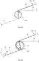
- FIG. 3A to FIG. 3D shows diagrams for illustrating a process of winding the members round the winding core 210 according to the present embodiment.
- the arrows in FIG. 3A to FIG. 3D indicate the directions of rotation of the winding core 210, but this is not intended to limit the directions of rotation of the winding core 210 to those directions.
- the asterisks in the figures are given to facilitate understanding of the orientations of rotation of the winding core 210.
- positive electrode tabs 22t and negative electrode tabs 24t are omitted in the figures for clarity.
- the tip of the first separator 71 (in other words, a winding initiation end 71a of the first separator) is clamped into the first slit Sa
- the tip of the second separator 72 (in other words, a winding initiation end 72a of the second separator) is claimed into the second slit Sb.
- the first slit Sa and the second slit Sb can serve as electrostatic chucks, and also fix the tip of the first separator 71 and the tip of the second separator 72 to the winding core 210.
- the above configuration is preferred because it can prevent formation of clamping marks and the like at the tip of the first separator 71 and the tip of the second separator 72.
- the first separator 71 and the second separator 72 are brought into contact with the winding core 210 by rotating the winding core 210 approximately half a revolution in the direction of the arrows to wind the first separator 71 and the second separator 72 around the winding core 210 (the first winding step).
- the first separator 71 is brought into contact with the winding core 210 on a side wall of the first slit Sa and on an approximately half a revolution of a side surface of the winding core 210 (see a first contact region A1 in FIG. 3B ) in the present embodiment.
- the second separator 72 is brought into contact with the winding core 210 on a side wall of the second slit Sb and on an approximately half a revolution of the side surface of the winding core 210 (see a second contact region A1 in FIG. 3B ).
- the formation of the second adhesive layer 82 on the surface of the second separator 72 with the coating applicator 230 is started (the second adhesive layer forming step). Further, the negative electrode sheet 24 is sandwiched between the first separator 71 which is wound around the winding core 210 and the second separator 72 which is fed. Subsequently, as shown in FIG. 3D , the formation of the first adhesive layer 81 on the surface of the first separator 71 with the coating applicator 230 is started (the first adhesive layer forming step) after rotating the winding core 210 approximately half a revolution. Further, the positive electrode sheet 22 is sandwiched between the second separator 72 which is wound around the winding core 210 and the first separator 71 which is fed.
- the positive electrode sheet 22 and the negative electrode sheet 24 are then wound around the winding core 210 along with the first separator 71 and the second separator 72 by rotating the winding core 210 in the direction of the arrows (the second winding step). Each member is then wound round the winding core 210 until the predetermined number of windings are completed. In this way, a wound body 20a can be obtained in which the positive electrode sheet 22 and the first separator 71 are bonded via the first adhesive layer 81, and the positive electrode sheet 22 and the second separator 72 are bonded via the second adhesive layer 82.
- the negative electrode sheet 24 is sandwiched at a timing when the first separator 71 and the second separator 72 are wound around the winding core 210 approximately half a revolution, but it is not limited to this.
- the negative electrode sheet 24 may be sandwiched at a timing when the first separator 71 is wound around the side wall of the first slit Sa and the winding core 210 approximately half a revolution, and the second separator 72 is wound around the side wall of the second slit Sb in view of preventing the adhesive layers from sticking to the winding core 210 as much as possible.
- the negative electrode sheet 24 may be sandwiched at a timing when the first separator 71 is wound around the side wall of the first slit Sa and the winding core 210 by approximately one revolution, and the second separator 72 is wound around the side wall of the second slit Sb and the winding core 210 by approximate one revolution.
- the timing of sandwiching the negative electrode sheet 24 can be adjusted according to the type of the wound electrode assembly to be manufactured, and the like.
- a starting position of forming the first adhesive layer 81 in the first separator 71 at the first adhesive layer forming step may be the same as a position where the positive electrode sheet 22 is sandwiched, or may be a position closer to the winding initiation end 71a of the first separator than the position where the positive electrode sheet 22 is sandwiched (for example, at a position 10 mm or 20 mm to the winding initiation end 71a of the first separator).
- a starting position of forming the second adhesive layer 82 in the second separator 72 at the second adhesive layer forming step may be the same as a position where the negative electrode sheet 24 is sandwiched, or may be a position closer to the winding initiation end 72a of the second separator than the position where the negative electrode sheet 24 is sandwiched (for example, at a position 10 mm or 20 mm to the winding initiation end 72a of the second separator).
- the adhesive layers can be more reliably formed at regions facing the positive electrode sheet 22 in the first separator 71 and the second separator 72.
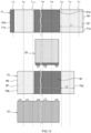
- the starting position of forming the first adhesive layer 81 in the first separator 71 is closer to the winding initiation end 71a of the first separator than the position where the positive electrode sheet 22 is sandwiched.
- the starting position of forming the second adhesive layer 82 on the second separator 72 is closer to the winding initiation end 72a of the second separator than the position where the negative electrode sheet 24 is sandwiched (see FIG. 13 and FIG. 14 ).
- a termination position of forming the first adhesive layer 81 in the first separator 71 may be a position facing a winding termination end 22T of the positive electrode sheet in the first separator 71, or a position closer to a winding termination end 71b of the first separator than the position facing the winding termination end 22T of the positive electrode sheet in the first separator 71 (for example, a position 10 mm or 20 mm to the winding termination end 71b of the first separator).
- a termination position of forming the second adhesive layer 82 in the second separator 72 may be a position facing a winding termination end 22T of the positive electrode sheet in the second separator 72, or a position closer to a winding termination end 72b of the second separator than the position facing the winding termination end 22T of the positive electrode sheet in the second separator 72 (for example, a position 10 mm or 20 mm to the winding termination end 72b of the second separator).
- the adhesive layers can be more reliably formed at the regions facing the positive electrode sheets 22 in the first separator 71 and the second separator 72.
- the termination position of forming the first adhesive layer 81 (in this case, a first adhesive layer 81a) in the first separator 71 is set to be closer to the winding termination end 71b of the first separator than the position facing the winding termination end 22T of the positive electrode sheet in the first separator 71.
- the termination position of forming the second adhesive layer 82 in the second separator 72 is closer to the winding termination end 72b of the second separator than the position facing the winding termination end 22T of the positive electrode sheet in the second separator 72 (see FIG. 13 and FIG. 14 ).
- a first adhesive layer 81b is formed in the vicinity of the winding termination end 71b in the first separator.
- the second adhesive layer 82 is not formed on an outermost surface in the second separator 72 (see FIG. 13 and FIG. 14 ).
- the wound electrode assembly 20 can be obtained in which the strip-shaped first separator 71, the strip-shaped positive electrode sheet 22, the strip-shaped second separator 72, and the strip-shaped negative electrode sheet 24 are wound around a winding axis WL in a predetermined direction of winding.
- the positive electrode sheet 22 and the first separator 71 are bonded via the first adhesive layer 81.
- the positive electrode sheet 22 and the second separator 72 are bonded via the second adhesive layer 82.
- the first separator 71 has a first region in the vicinity of the winding initiation end 71a of the first separator.
- the first region there exists a region where the first adhesive layer 81 is not formed and/or a region where the first adhesive layer 81 is formed having a basis weight less than that of the first adhesive layer 81 formed at a region facing the positive electrode sheet 22 in the first separator 71.
- the second separator 72 has a second region in the vicinity of the winding initiation end 72a of the second separator. In the second region, there exists a region where the second adhesive layer 82 is not formed and/or a region where the second adhesive layer 82 is formed having a basis weight less than that of the second adhesive layer 82 formed at a region facing the positive electrode sheet 22 in the second separator 72.
- the first adhesive layer 81 may not be formed throughout the entire first region, or the first adhesive layer 81 may be formed throughout the entire first region. Alternatively, in the first region, there may exist the region where the first adhesive layer 81 is not formed and a region where the first adhesive layer 81 is formed.
- the second adhesive layer 82 may not be formed throughout the entire second region, or the second adhesive layer 82 may be formed throughout the entire second region. Alternatively, in the second region, there may exist the region where the second adhesive layer 82 is not formed and a region where the second adhesive layer 82 is formed.
- the first region in the vicinity of the winding initiation end of the first separator may be a region up to, for example, 50%, 100%, 120%, 150%, 200% from the winding initiation end 71a of the first separator when the length of the innermost circumference of the winding core 210 is 100%.
- it may be a region up to, for example, 50%, 100%, 120%, 150%, 200% from the winding initiation end 71a of the first separator when the length of the innermost circumference of the wound electrode assembly 20 is 100%.
- the vicinity of the winding initiation end 71a of the first separator is defined as a region within 2 cm from the winding initiation end 71a of the first separator.
- the second region in the vicinity of the winding initiation end of the second separator may be a region up to, for example, 50%, 60%, 80%, 100%, 120%, 150%, 200% from the winding initiation end 72a of the second separator when the length of the innermost circumference of the winding core 210 is 100%.
- it may be a region up to, for example, 50%, 60%, 80%, 100%, 120%, 150%, 200% from the winding initiation end 72a of the second separator when the length of the innermost circumference of the wound electrode assembly 20 is 100%.
- the vicinity of the winding initiation end 72a of the second separator is defined as a region within 2 cm from the winding initiation end 72a of the second separator.
- a "basis weight" means a value calculated by dividing the mass of an adhesive layer by the area of a formed region (mass of adhesive layer/area of formed region).
- the region where the first adhesive layer 81 is not formed is present in the first region (in this case, the first contact region A1 and a region A3) in the vicinity of the winding initiation end 71a of the first separator. Further, the region where the second adhesive layer 82 is not formed is present in the second region (in this case, the second contact region A2) in the vicinity of the winding initiation end 72a of the second separator (see FIG. 14 ).
- the battery 100 comprising the wound electrode assembly 20 as described above includes the wound electrode assembly 20 in which the strip-shaped first separator 71, the strip-shaped positive electrode sheet 22, the strip-shaped second separator 72, and the strip-shaped negative electrode sheet 24 are wound around the winding axis WL in the predetermined direction of winding.
- the positive electrode sheet 22 and the first separator 71 are bonded via the first adhesive layer 81 in the wound electrode assembly 20.
- the positive electrode sheet 22 and the second separator 72 are bonded via the second adhesive layer 82.
- the method of manufacturing a battery as described above comprises: the first adhesive layer forming step, the second adhesive layer forming step, the first winding step, and the second winding step.
- the first adhesive layer forming step is a step of forming the first adhesive layer 81 on the surface of the first separator 71.
- the second adhesive layer forming step is a step of forming the second adhesive layer 82 on the surface of the second separator 72.
- the first winding step is a step of bringing the first separator 71 and the second separator 72 into contact with the winding core 210, and winding the first separator 71 and the second separator 72 around the winding core 210.
- the second winding step is a step of winding the positive electrode sheet 22 and the negative electrode sheet 24 around the winding core 210 along with the first separator 71 and the second separator 72.
- the first adhesive layer 81 having a predetermined basis weight is formed at the region facing the positive electrode sheet 22, and the region where the first adhesive layer 81 is not formed and/or the region where the first adhesive layer 81 is formed having a basis weight less than that of the region facing the positive electrode sheet 22 in the first separator 71 are formed in a predetermined first region in the vicinity of the winding initiation end 71a of the first separator.
- the second adhesive layer 82 having a predetermined basis weight is formed at the region facing the positive electrode sheet 22, and the region where the second adhesive layer 82 is not formed and/or the region where the second adhesive layer 82 is formed having a basis weight less than that of the region facing the positive electrode sheet 22 in the second separator 72 are formed in a predetermined second region in the vicinity of the winding initiation end 72a of the second separator.
- the first adhesive layer 81 may be formed throughout the entire first region, or the first adhesive layer 81 may not be formed throughout the entire first region. Alternatively, the region where the first adhesive layer 81 is not formed and the region where the first adhesive layer 81 is formed may be formed in the first region. Further, in the method of manufacturing a battery as disclosed herein, the second adhesive layer 82 may be formed throughout the entire second region, or the second adhesive layer 82 may be formed throughout the entire second region. Alternatively, the region where the second adhesive layer 82 is not formed and the region where the second adhesive layer 82 is formed may be formed in the second region.
- the method of manufacturing a battery of such a configuration no adhesive layers are formed in the vicinity of the winding initiation end of either the first separator 71 or the second separator 72, or the adhesive layers to be formed have a lower basis weight.
- This can suitably reduce the amount of the adhesive layers adhering to the winding core 210. Accordingly, the amount of the adhesive layers would be small even if the adhesive layers do adhere to the winding core 210.
- This can prevent inhibition of continuous production of the wound electrode bodies 20 due to the adhesive layers adhering to the winding core 210, and can suitably suppress a decreased yield of the wound electrode bodies 20.
- the battery 100 comprising the wound electrode assembly 20 can be obtained with high productivity, the wound electrode assembly 20 including the separators having adhesive layers.
- the ratio (B/A) of a basis weight B of the first adhesive layer 81 in the first region to a basis weight A of the first adhesive layer 81 in the region facing the positive electrode sheet 22 may be, for example, 0.9 or less, and in view of suitably controlling the amount of the first adhesive layer 81 that may adhere to the winding core 210, it may be preferably 0.8 or less, more preferably 0.5 or less, particularly preferably 0.3 or less, and for example, it may be 0.1 or less.
- the ratio (D/C) of a basis weight D of the second adhesive layer 82 in the second region to a basis weight C of the second adhesive layer 82 in the region facing the positive electrode sheet 22 may be, for example, 0.9 or less, and in view of suitably controlling the amount of the second adhesive layer 82 that may adhere to the winding core 210, it may be preferably 0.8 or less, more preferably 0.5 or less, particularly preferably 0.3 or less, and for example, it may be 0.1 or less
- the first adhesive layer 81 having a predetermined basis weight is formed in the region facing the positive electrode sheet 22, and the region where the first adhesive layer 81 is not formed is formed in the first region predetermined in the vicinity of the winding initiation end 71a of the first separator (in this case, the first contact region A1 and the region A3).
- the second adhesive layer forming step the second adhesive layer 82 having a predetermined basis weight is formed in the region facing the positive electrode sheet 22, and the region where the second adhesive layer 82 is not formed is formed in the second region predetermined in the vicinity of the winding initiation end 72a of the second separator (in this case, the second contact region A2).
- the adhesive layer forming steps in this case, the first adhesive layer forming step and the second adhesive layer forming step
- the winding steps in this case, the first winding step and the second winding step
- the adhesive layer forming steps are performed successively.
- blocking e.g., unintended adhesion between the adhesive layers and the separators
- the separators do not need to be kept in a state where they are wound around the reels. This is preferred because the wound electrode bodies having the desired amount of adhesive layers formed in desired positions can be more reliably obtained.
- a distance between a position where the adhesive layer is formed (in this case, a position where the coating applicator 230 is present) and a position of the winding core 210 may be, for example, less than 50 m, and may be less than 10 m or less than 3 m.
- a period of time between the completion of the adhesive layer forming steps and the start of the winding steps may be, for example, less than 60 minutes, less than 20 minutes, or less than 5 minutes. It is noted that the distances and the period of time as described above may be altered as appropriate depending on actual embodiments.
- a region where the first adhesive layer 81 is not formed in the first contact region (in this case, the first contact region A1) in contact with the winding core 210 in the first separator 71 and/or a region where the first adhesive layer 81 is formed having a basis weight less than that of the first adhesive layer 81 formed at the region facing the positive electrode sheet 22 in the first separator 71 may be formed at the first winding step.
- a region where the second adhesive layer 82 is not formed in the second contact region (in this case, the second contact region A2) in contact with the winding core 210 in the second separator 72 and/or a region where the second adhesive layer 82 is formed having a basis weight less than that of the second adhesive layer 82 formed at the region facing the positive electrode sheet 22 in the second separator 72 may be formed at the first winding step.
- the first adhesive layer 81 may not be formed throughout the entire first contact region, or the first adhesive layer 81 may be formed throughout the entire first contact region. Alternatively, the region where the first adhesive layer 81 is formed and the region where the first adhesive layer 81 is not formed may be formed in the first contact region. Further, in the method of manufacturing a battery as disclosed herein, the second adhesive layer 82 may not be formed throughout the entire second contact region, or the second adhesive layer 82 may be formed throughout the entire second contact region. Alternatively, the region where the second adhesive layer 82 is formed and the region where the second adhesive layer 82 is not formed may be formed in the second contact region.
- the method of manufacturing a battery of such a configuration no adhesive layers are formed in regions in contact with the winding core 210 either in the first separator 71 or the second separator 72, or the adhesive layers to be formed have a lower basis weight.
- This can suitably suppress the amount of the adhesive layers adhering to the winding core 210. Accordingly, the amount of the adhesive layers would be small even if the adhesive layers do adhere to the winding core 210.
- This can prevent inhibition of continuous production of the wound electrode bodies 20 due to the adhesive layers adhering to the winding core 210, and can more suitably suppress a decreased yield of the wound electrode bodies 20.
- the battery 100 comprising the wound electrode assembly 20 can be obtained with high productivity, the wound electrode assembly 20 including the separators having adhesive layers.
- the ratio (F/E) of a basis weight F of the first adhesive layer 81 in the first contact region to a basis weight E of the first adhesive layer 81 in the region facing the positive electrode sheet 22 may be, for example, 0.9 or less, and in view of suitably controlling the amount of the first adhesive layer 81 that may adhere to the winding core 210, it may be preferably 0.8 or less, more preferably 0.5 or less, particularly preferably 0.3 or less, and for example, it may be 0.1 or less.
- the ratio (H/G) of a basis weight H of the second adhesive layer 82 in the second contact region to a basis weight G of the second adhesive layer 82 in the region facing the positive electrode sheet 22 may be, for example, 0.9 or less, and in view of suitably controlling the amount of the second adhesive layer 82 that may adhere to the winding core 210, it may be preferably 0.8 or less, more preferably 0.5 or less, particularly preferably 0.3 or less, and for example, it may be 0.1 or less.
- a region where the first adhesive layer 81 is not formed throughout the entire first contact region A1 is formed, and a region where the second adhesive layer 82 is not formed throughout the entire second contact region A2 is formed.
- a timing of starting adhesive application on the first separator 71 is delayed by half a revolution than a timing of starting adhesive application on the second separator 72. That is, in the present embodiment, a region extending to a region other than the first contact region A1 in which the region where the first adhesive layer 81 is not formed (see the region A3 in FIG. 3D ) is formed in the first separator 71.
- the region A3 in this case represents a region where the second separator 72 is positioned between the first separator 71 and the winding core 210.
- the first region may be formed so as to extend to a region other than the first contact region (in this case, the first contact region A1) in the first separator 71.
- the first contact region A1 in the first separator 71.
- the region extending to a region other than the first contact region A1 in which the region where the first adhesive layer 81 is not formed is formed in the first separator 71.
- the first region and the second region may be formed so that a length L1 from the winding initiation end 71a of the first separator in a longitudinal direction of the first region is longer than a length L2 from the winding initiation end 72a of the second separator in a longitudinal direction of the second region.
- the first region and the second regions are formed so that the length L1 from the winding initiation end 71a of the first separator in the longitudinal direction of the first region (in this case, the first contact region A1 and the region A3) is longer than the length L2 from the winding initiation end 72a of the second separator in the longitudinal direction of the second region (in this case, the second contact region A2) (see FIG. 13 ).
- the ratio (L1/L2) of the length L1 from the winding initiation end 71a of the first separator in the longitudinal direction of the first region to the length L2 from the winding initiation end 72a of the second separator in the longitudinal direction of the second region may be, for example, 1.2 or more, and in view of easier achievement of the aforementioned effects, it may be preferably 1.5 or more, or 2 or more. Further, the upper limit of the above ratio (L1/L2) may be, for example, 3 or less, or 2.5 or less.
- a region where a corresponding adhesive layer i.e., the first adhesive layer 81 and/or the second adhesive layer 82
- a region where a corresponding adhesive layer is formed having a basis weight less than that of a corresponding adhesive layer formed at a region facing the positive electrode sheet 22 in a corresponding separator may be formed in an region corresponding to the outermost surface of the wound electrode assembly 20 in the first separator 71 and the second separator 72.
- the corresponding adhesive layer may not be formed throughout the entire region corresponding to the outermost surface of the wound electrode assembly 20, or the corresponding adhesive layer may be formed throughout the entire region corresponding the outermost surface of the wound electrode assembly 20. Alternatively, a region where the corresponding adhesive layer is formed and a region where the corresponding adhesive layer is not formed may be formed in the region corresponding to the outermost surface of the wound electrode assembly 20. According to the method of manufacturing a battery of such a configuration, adhesion of the adhesive layers to the electrode assembly-manufacturing device 200 can be suitably prevented, and thus the productivity of the battery 100 comprising the wound electrode assembly 20 including the adhesive layers can be more suitably improved.
- the ratio (J/I) of a basis weight J of the corresponding adhesive layer in the region corresponding to the outermost surface of the wound electrode assembly 20 to a basis weight I of the corresponding adhesive layer in the region facing the positive electrode sheet 22 may be, for example, 0.9 or less, 0.8 or less, 0.5 or less, 0.3 or less, or 0.1 or less.
- the region where the first adhesive layer 81 is not formed is formed in the region corresponding to the outermost surface of the wound electrode assembly 20 in the first separator 71 (see P in FIG. 14 ).
- the first adhesive layer 81b having a basis weight less than that of the first adhesive layer 81a in the region facing the positive electrode sheet 22 is formed in the vicinity of the winding termination end 71b of the first separator on a surface of a side where the first adhesive layer 81 is formed (see FIG 14 ).
- the second adhesive layer 82 is not formed on the outermost surface in the second separator 72.
- the "vicinity of the winding termination end of the first separator” may be a region within, for example, 5%, 10%, or 20% from the winding termination end 71b of the first separator when the length of the outermost circumference of the wound electrode assembly 20a is 100%. Alternatively, it may be a region up to 5%, within 10%, or within 20% from the winding termination end 71b of the first separator when the length of the outermost circumference of the wound electrode assembly 20 is 100%.
- the vicinity of the winding termination end 71b of the first separator is defined as a region within 2 cm from the winding termination end 71b of the first separator.
- the first separator 71 is fed to the winding core 210 from one side of the vertical line li
- the second separator 72 is fed to the winding core 210 from the other side of the vertical line l 1 at the first winding step.
- a position of the winding termination end 71a of the first separator, a position of the winding termination end 72a of the second separator, the length of each separator, and a cutting position can be suitably adjusted.
- the positive electrode sheet 22 is fed to the winding core 210 from the same side as the first separator 71 with respect to the vertical line li, and the negative electrode sheet 24 is fed to the winding core 210 from the other side of the second separator with respect to the vertical line l 1 .
- the first separator 71 is then fed from above the positive electrode sheet 22, and the second separator 72 is fed from below the negative electrode sheet 24.
- the first adhesive layer 81 is preferably formed in the first separator 71 when passing a region where the angle ⁇ k3 between the transport path k3 and the straight line l 2 passing through the winding center O of the winding core 210 and extending in the horizontal direction is, for example, -30° to +30° (preferably, -15° to +15°).
- the second adhesive layer 82 is preferably formed in the first separator 72 when passing a region where the angle ⁇ k4 between the transport path k4 and the straight line l 2 passing through the winding center O of the winding core 210 and extending in the horizontal direction is, for example, -30° to +30° (preferably, -15° to +15°). This can ameliorate uneven application in the width direction of the separators, leading to formation of more uniform adhesive layers.
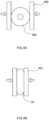
- FIG. 4A and FIG. 4B illustrate the pressing step.
- the pressing step the wound body 20a manufactured as described above is withdrawn from the winding core 210 and pressed with a press machine 300.
- the wound electrode assembly 20 in a flattened shape can be suitably obtained. It is also preferred that pressing is performed so that an adhesive strength of the positive electrode sheet 22 and the first separator 71 after the pressing step is greater than that of the positive electrode sheet 22 and the first separator 71 before the pressing step.
- pressing is preferably performed so that the adhesive strength between the positive electrode sheet 22 and the second separator 72 after the pressing step is also greater than that between the positive electrode sheet 22 and the second separator 72 before the pressing step.
- the method of manufacturing a battery of such a configuration an opportunity to loosen the wound body 20a after winding can be given in order to suppress buckling. Therefore, this is preferred.
- the ratio (N/M) of an adhesive strength M of the positive electrode sheet 22 and the first separator 71 before the pressing step to an adhesive strength N of the positive electrode sheet 22 and the first separator 71 after the pressing step may be, for example, 1.2 or more, 1.5 or more, or 2 or more. It is noted that such an adhesion strength may mean, for example, an adhesion strength measured by a conventionally known measurement method using a positive electrode sheet-separator laminated body of a predetermined area (e.g., a sample in 5 cm x 5 cm).
- the ratio of the adhesion strength of the positive electrode sheet 22 and the second separator 72 before the pressing step to the adhesion strength of the positive electrode sheet 22 and the second separator 72 after the pressing step can also be referred to the above description.
- the battery 100 can be made by preparing three of the wound electrode bodies 20, and inserting them into a battery case 10, and sealing it. Specifically, as shown in FIG. 6 , a positive electrode second current collecting member 52 is joined to a positive electrode tab group 25 of the wound electrode assembly 20, and an negative electrode second current collecting member 62 is joined to an negative electrode tab group 27. Then, as shown in FIG. 9 , a plurality (in this case, three) of wound electrode bodies are arranged so that flattened portions are facing each other. A sealing plate 14 is placed above the plurality of wound electrode bodies 20, and the positive electrode tab group 25 of each of the wound electrode bodies 20 is bent so that the positive electrode second current collecting member 52 and one side surface 20e of the wound electrode assembly 20 are facing each other.
- the battery case 10 is then constructed by joining (welding) the exterior body 12 with the sealing plate 14. After this, an electrolyte is injected into the battery case 10 through an injection hole 15 in the sealing plate 14, and the injection hole 15 is then sealed with a sealing member 16. As described above, the battery 100 can be manufactured.
- FIG. 5 shows a perspective view of the battery 100.
- FIG. 6 shows a schematic longitudinal sectional view along the VI-VI line in FIG. 5 .
- FIG. 7 shows a schematic longitudinal sectional view along the VII-VII line in FIG. 5 .
- FIG. 8 shows a schematic cross sectional view along the VIII-VIII line in FIG. 5 .
- FIG. 9 shows a perspective view schematically illustrating electrode bodies attached to the sealing plate.
- FIG. 10 shows a perspective view schematically illustrating an electrode assembly to which the positive electrode second current collector and the negative electrode second current collector are attached.
- FIG. 11 shows the structure of the wound electrode assembly. It is noted that in FIG. 11 , illustration of the first adhesive layer 81 and the second adhesive layer 82 is omitted for clarity.
- the battery 100 comprises the wound electrode assembly 20 and the battery case that houses the wound electrode assembly 20. Although not shown in the figures, the battery 100 further comprises an electrolyte, here.
- the battery 100 is preferably a non-aqueous electrolyte secondary battery, for example, a lithium ion secondary battery and the like.
- the battery case 10 is a housing which houses the wound electrode assembly 20.
- the battery case 10 has a bottomed rectangular (square) outer shape, as shown in FIG. 5 .
- the material of the battery case 10 may be the same as conventionally used, without any particular restrictions.
- the battery case 10 is preferably made of a metal. Examples of materials which can be used for the battery case 10 include aluminum, aluminum alloys, iron, iron alloys, and the like.
- the battery case 10 comprises the exterior body 12 and the sealing plate 14.
- the exterior body 12 is a flat-bottomed square container having an opening 12h at the top surface.
- the exterior body 12 comprises a substantially rectangular bottom wall 12a in a plan view, a pair of longer side walls 12b extending from the bottom wall 12a and facing each other, and a pair of shorter side walls 12c extending from the bottom wall 12a and facing each other.
- the area of the shorter side wall 12c is smaller than that of the longer side wall 12b.
- the sealing plate 14 is a member for sealing the opening 12h of the exterior body 12, and is a substantially rectangular plate-shaped member in a plan view.
- the battery case 10 is integrated by joining (e.g., welding joint) the sealing plate 14 to a periphery of the opening 12h of the exterior body 12.
- the battery case 10 is sealed airtightly (closed tightly).
- the sealing plate 14 has the injection hole 15, a gas discharge valve 17, and two terminal withdrawal holes 18 and 19.
- the injection hole 15 is a through hole for pouring an electrolytic solution into the battery case 10 after fixing the sealing plate 14 to the exterior body 12.
- the injection hole 15 is sealed with the sealing member 16 after pouring of the electrolytic solution.
- the gas discharge valve 17 is a thin-walled section configured to break when the pressure inside the battery case 10 exceeds a predetermined value to discharge gas inside the battery case 10 to the outside.
- the electrolyte may be accommodated in the battery case 10 along with the wound electrode assembly 20.
- the electrolyte those used in conventionally known batteries can be used without any particular restrictions.
- a non-aqueous electrolytic solution can be used in which a supporting salt is dissolved in a non-aqueous solvent.
- the non-aqueous solvent include carbonate-based solvents such as ethylene carbonate, dimethyl carbonate, and ethylmethyl carbonate.
- the supporting salt include fluorine-containing lithium salts such as LiPF 6 .
- the non-aqueous electrolytic solution may contain various types of additives if needed. It is noted that the electrolyte may be in a solid state (a solid electrolyte) and may be integrated with the electrode assembly.
- a positive electrode terminal 30 is attached to one end of the sealing plate 14 in a longitudinal direction Y (the left side in FIG. 5 and FIG. 6 ).
- An negative electrode terminal 40 is attached to the other end of the sealing plate 14 in the longitudinal direction Y (the right side in FIG. 5 and FIG. 6 ).
- the positive electrode terminal 30 and the negative electrode terminal 40 are inserted into the terminal withdrawal holes 18, 19, and exposed to the outer surface of the sealing plate 14.
- the positive electrode terminal 30 is electrically connected to a plate-shaped positive electrode external conductive member 32 at the outside of the battery case 10.
- the negative electrode terminal 40 is electrically connected to a plate-shaped positive electrode external conductive member 42 at the outside of the battery case 10.
- the positive electrode external conductive member 32 and the negative electrode external conductive member 42 are connected to another rechargeable battery or another external device via an external connection member such as a bus bar.
- the positive electrode external conductive member 32 and the negative electrode external conductive member 42 are preferably made of a metal having excellent conductivity, for example, aluminum, aluminum alloys, copper, copper alloys, and the like.
- the positive electrode external conductive member 32 and the negative electrode external conductive member 42 are not essential, and can be omitted in other embodiments.
- the battery 100 has a plurality (three) of wound electrode bodies 20 housed in the battery case 10, in this case.
- the detailed structure of the wound electrode bodies 20 will be described below.
- Each of the wound electrode bodies 20 has the positive electrode tab group 25 and the negative electrode electrode tab group 27 (see FIG. 8 ). As shown in FIG. 8 , these electrode tab groups (the positive electrode tab group 25 and the negative electrode tab group 27) are bent in a state where the electrode current collectors (the positive electrode current collector 50 and the negative electrode current collector 60) are joined.
- the positive electrode tab group 25 of each of the plurality of wound electrode bodies 20 is connected to the positive electrode terminal 30 via the positive electrode current collector 50.
- the positive electrode current collector 50 is housed in the inside of the battery case 10.
- the positive electrode current collector 50 comprises the positive electrode first current collecting member 51 and the positive electrode second current collecting member 52 as shown in FIG. 6 and FIG. 9 .
- the positive electrode first current collecting member 51 is a plate-shaped conductive member extending in the longitudinal direction Y along an inner surface of the sealing plate 14.
- the positive electrode second current collecting member 52 is a plated-shaped conductive member extending along a vertically direction Z of the battery 100.
- a lower end 30c of the positive electrode terminal 30 is then inserted into the inside of the battery case 10 through the terminal withdrawal hole 18 of the sealing plate 14, and connected to the positive electrode first current collecting member 51 (see FIG. 6 ).
- the battery 100 has a number of positive electrode second current collecting members 52 corresponding to the number of the plurality of wound electrode bodies 20, in this case.
- Each of the positive electrode second current collecting members 52 are connected to the corresponding positive electrode tab group 25 of the wound electrode bodies 20.
- the positive electrode tab group 25 of the wound electrode bodies 20 is bent so that the positive electrode second current collecting members 52 and the one side surfaces 20e of the wound electrode bodes 20 are facing each other.
- the positive electrode terminal 30 and the positive electrode current collector 50 are preferably composed of a metal with excellent conductivity.
- the positive electrode terminal 30 and the positive electrode current collector 50 may be made of, for example, aluminum or an aluminum alloy.
- the negative electrode tab group 27 of each of the plurality of wound electrode bodies 20 is connected to the negative electrode terminal 40 via the negative electrode current collector 60.
- the negative electrode current collector 60 comprises the negative electrode first current collecting member 61 and the negative electrode second current collecting member 62 as shown in FIG. 6 and FIG. 9 .
- the negative electrode first current collecting member 61 is a plate-shaped conductive member extending in the longitudinal direction Y along the inner surface of the sealing plate 14.
- the negative electrode second current collecting member 62 is a plated-shaped conductive member extending along the vertically direction Z of the battery 100.
- a lower end 40c of the negative electrode terminal 40 is then inserted into the inside of the battery case 10 through the terminal withdrawal hole 19, and connected to the negative electrode first current collecting member 61 (see FIG. 6 ).
- the battery 100 has a number of negative electrode second current collecting members 62 corresponding to the number of the plurality of wound electrode bodies 20, in this case.
- the negative electrode second current collecting members 62 is connected to the negative electrode tab group 27 of the wound electrode bodies 20, respectively.
- the negative electrode tab group 27 of the wound electrode bodies 20 is then bent so that the negative electrode second current collecting members 62 and the one side surfaces 20h of the wound electrode bodes 20 are facing each other.
- the negative electrode terminal 40 and the negative electrode current collector 60 are preferably made of a metal with excellent conductivity.
- the negative electrode terminal 40 and the negative electrode current collector 60 may be made of, for example, copper or a copper alloy.
- various insulating members are installed to prevent conduction between the wound electrode bodies 20 and the battery case 10.
- the positive electrode external conductive member 32 and the negative electrode external conductive member 42 are insulated from the sealing plate 14 by external insulating members 92.
- a gasket 90 is fit to each of the terminal withdrawal holes 18, 19 of the sealing plate 14. This can prevent conduction of the positive electrode terminal 30 (or the negative electrode terminal 40) inserted into the terminal withdrawal holes 18, 19 with the sealing plate 14.
- an inner insulating member 94 is disposed between the positive electrode current collector 50 and the negative electrode current collector 60 and the inner surface side of the sealing plate 14.
- the inner insulating member 94 may comprise a protrusion protruding toward the wound electrode assembly 20. Further, the plurality of wound electrode bodies 20 covered with the electrode assembly holder 29 (see FIG. 7 ) made of an insulating resin sheet are placed in the inside of the exterior body 12. This can prevent direct contact between the wound electrode bodies 20 and the exterior body 12. It is noted that there is no particular limitation for the material of each of the aforementioned insulating members as long as it has predefined insulating properties.
- Such a material examples include polyolefin-based resins such as polypropylene (PP) and polyethylene (PE); and synthetic resin materials such as fluorinated resins, for example, perfluoroalkoxyalkane, polytetrafluoroethylene (PTFE).
- PP polypropylene
- PE polyethylene
- fluorinated resins for example, perfluoroalkoxyalkane, polytetrafluoroethylene (PTFE).
- wound electrode bodies 20 are housed in the exterior body 12.
- the wound electrode assembly 20 is preferably flattened.
- the wound electrode assembly 20 which is, for example, flattened, has a pair of curved portions 20r facing the bottom wall 12a of the exterior body 12 and the sealing plate 14, and a flattened portion 20f connecting the pair of curved portions 20r and facing the longer side wall 12b of the exterior body 12.
- a flattened wound electrode assembly refers to a wound electrode assembly that is substantially oval in a cross-sectional view and has a so-called race-track shape (see FIG 3 ).
- the wound electrode bodies 20 are stacked in a manner where the strip-shaped positive electrode sheet 22 and the strip-shaped negative electrode sheet 24 are insulated via the strip-shaped first separator 71 and the strip-shaped second separator 72, and configured so as to be wound around the winding axis WL in the longitudinal direction.
- the wound electrode assembly 20 is placed in the inside the exterior body 12 in an orientation where the winding axis WL (see FIG. 11 ) is parallel to the longitudinal direction Y of the exterior body 12.
- the wound electrode assembly 20 is placed in the inside of the exterior body 12 in an orientation where the winding axis WL is parallel to the bottom wall 12a and is orthogonal to the shorter side wall 12c.
- An end face of the wound electrode assembly 20 (in other words, a stacked face of the positive electrode sheet 22 and negative electrode sheet 24) faces the shorter side wall 12c.
- the positive electrode sheet 22 is a strip-shaped member as shown in FIG. 11 .
- the positive electrode sheet 22 has a strip-shaped positive electrode current collector 22c; and a positive electrode active material layer 22a and a positive electrode protective layer 22p adhered on at least one surface of the positive electrode current collector 22c.
- the positive electrode protective layer 22p is not essential, and can be omitted in other embodiments.
- the positive electrode current collector 22c is preferably made of a conductive metal such as aluminum, aluminum alloys, nickel, stainless steel, and the like. In this case, the positive electrode current collector 22c is a metal foil, specifically an aluminum foil.
- the plurality of positive electrode tabs 22t are provided at one end of the wound electrode assembly 20 in the longitudinal direction Y (a left end in FIG. 11 ), as shown in FIG. 11 .
- the plurality of positive electrode tabs 22t are provided at predetermined intervals (intermittently) along the longitudinal direction.
- the positive electrode tabs 22t are connected to the positive electrode sheet 22.
- the positive electrode tabs 22t are a part of the positive electrode current collector 22c and made of a metal foil (specifically, an aluminum foil).
- the positive electrode tabs 22t represent regions where the positive electrode active material layer 22a is not formed, and the positive electrode current collector 22c is exposed.
- the positive electrode tabs 22t may have the positive electrode active material layer 22a and/or the positive electrode protective layer 22p partially formed, and may be a separate member from the positive electrode current collector 22c.
- the plurality of positive electrode tabs 22t are each trapezoidal in shape.
- the shape of the positive electrode tabs 22t is not limited to this.
- the plurality of positive electrode tabs 22t are stacked at one end of the positive electrode sheet 22 in the longitudinal direction Y (the left end in FIG. 8 ) to form the positive electrode tab group 25.
- the positive electrode active material layer 22a is provided in a strip manner along the longitudinal direction of the strip-shaped positive electrode current collector 22c, as shown in FIG. 11 .
- the positive electrode active material layer 22a contains a positive electrode active material (e.g., lithium transition metal composite oxides such as lithium nickel cobalt manganese composite oxides) that can reversibly occlude and release charge carriers.
- the positive electrode active material layer 22a preferably contains a lithium transition metal composite oxide as a positive electrode active material, and the lithium transition metal composite oxide preferably has a high content of nickel (Ni).
- the content of nickel may preferably be 55 mol% or more, more preferably 70 mol% or more, and even more preferably 75 mol% or more when the total of metal elements other than lithium is 100 mol%. This can achieve an even higher capacity of a non-aqueous electrolyte secondary battery.
- the positive electrode active material layer 22a may generally account for 80 mass% or more, typically 90 mass% or more, for example, 95 mass% or more.
- the positive electrode active material layer 22a may contain an optional component, such as conductive materials, binders, and various additive components, other than the positive electrode active material.
- conductive materials include carbon materials such as acetylene black (AB).
- binders include fluorinated resins such as poly(vinylidene fluoride) (PVdF).
- the ratio (b/a) of the amount of moisture b to the weight a is preferably less than 0.2%.
- the positive electrode protective layer 22p is a layer configured so as to have lower electrical conductivity than the positive electrode active material layer 22a.
- the positive electrode protective layer 22p is provided in the longitudinal direction Y at the boundary between the positive electrode current collector 22c and the positive electrode active material layer 22a, as shown in FIG. 11 .
- the positive electrode protective layer 22p is provided in the longitudinal direction Y at one end of the positive electrode current collector 22c (the left end in FIG. 11 ).
- the positive electrode protective layer 22p may be provided at the both ends in the longitudinal direction Y
- the positive electrode protective layer 22p can prevent internal short circuit in the battery 100 due to direct contact between the positive electrode current collector 22c and the negative electrode active material layer 24a in case the first separator 71 and the second separator 72 are damaged.
- the positive electrode protective layer 22p contains an insulating inorganic filler, for example, ceramic particles such as alumina. When the total solid content of the positive electrode protective layer 22p is 100 mass%, the inorganic filler may generally account for 50 mass% or more, typically 70 mass% or more, for example, 80 mass% or more.
- the positive electrode protective layer 22p may contain an optional component, such as conductive materials, binders, and various additive components, other than the inorganic filler. Conductive materials and binders may be the same as those exemplified as can be included in the positive electrode active material layer 22a.
- the negative electrode sheet 24 is a strip-shaped member as shown in FIG. 11 .
- the negative electrode sheet 24 has a strip-shaped negative electrode current collector 24c; and the negative electrode active material layer 24a adhered on at least one surface of the negative electrode current collector 24c.
- the negative electrode current collector 24c is preferably made of a conductive metal such as copper, copper alloys, nickel, stainless steel, and the like. In this case, the negative electrode current collector 24c is a metal foil, specifically a copper foil.
- the plurality of negative electrode tabs 24t are provided at one end of the wound electrode assembly 20 in the longitudinal direction Y (a right end in FIG. 11 ), as shown in FIG. 11 .
- the plurality of negative electrode tabs 24t are provided at predetermined intervals (intermittently) along the longitudinal direction.
- the negative electrode tabs 24t are connected to the negative electrode sheet 24.
- the negative electrode tabs 24t are a part of the negative electrode current collector 24c and made of a metal foil (specifically, an aluminum foil).
- the negative electrode tabs 24t represent regions where the negative electrode active material layer 24a is not formed and the negative electrode current collector 24c is exposed.
- the negative electrode tabs 24t may have the negative electrode active material layer 24a partially formed, and may be a separate member from the negative electrode current collector 24c.
- the plurality of negative electrode tabs 24t are each trapezoidal in shape.
- the shape and size of the plurality of negative electrode tabs 24t can be suitably adjusted as in the positive electrode tabs 22t. As shown in FIG. 8 , the plurality of negative electrode tabs 24t are stacked at one end of the negative electrode sheet 24 in the longitudinal direction Y (the right end in FIG. 8 ) to form the negative electrode tab group 27.
- the negative electrode active material layer 24a is provided in a strip manner along the longitudinal direction of the strip-shaped negative electrode current collector 24c, as shown in FIG. 11 .
- the negative electrode active material layer 24a contains an negative electrode active material (for example, carbon materials such as graphite) that can reversibly occlude and release change carriers.
- the width of the negative electrode active material layer 24a (the length in the longitudinal direction Y The same shall apply hereinafter.) may be preferably larger than the width of the positive electrode active material layer 22a.
- the negative electrode active material may generally account for 80 mass% or more, typically 90 mass% or more, for example, 95 mass% or more.
- the negative electrode active material layer 24a may contain an optional component, such as conductive materials, binders, dispersing agents, and various additive components, other than the negative electrode active material.
- binders include gums such as styrene-butadiene gum (SBR).
- dispersing agents include celluloses such as carboxymethylcellulose (CMC).
- the first separator 71 and the second separator 72 are strip-shaped members.
- the first separator 71 and the second separator 72 are insulating sheets with a plurality of fine through holes through which charge carriers can pass.
- the widths of the first separator 71 and the second separator 72 are larger than the width of the negative electrode active material layer 24a.
- a microporous membrane used for conventionally known battery separators can be used without any particular restrictions.
- the base material layer 85 is preferably a porous sheet-shaped member.
- the base material layer 85 may be of a single-layer structure, or of a structure of two or more layers, for example, of a three-layer structure.
- the base material layer 85 is preferably composed of polyolefin resin. This ensures sufficient flexibility of the separators, facilitating fabrication (winding and press forming) of the wound electrode assembly 20.
- Polyolefin resin is preferably polyethylene (PE), polypropylene (PP), or a mixture thereof is preferred, and is more preferably composed of PE.
- the thickness of the base material layer 85 is preferably 3 ⁇ m or more and 25 ⁇ m or less, more preferably 3 ⁇ m or more and 18 ⁇ m or less, and even more preferably 5 ⁇ m or more and 14 ⁇ m or less.
- a heat resistant layer 87 is provided on the base material layer 85 in this case.
- the heat resistant layer 87 may be provided directly on the surface of the base material layer 85 or on the base material layer 85 via another layer(s).
- the heat resistant layer 87 is not essential, and can be omitted in other embodiments.
- the basis weight of the heat resistant layer 87 is homogeneous in the longitudinal and width direction of the separators.
- the thickness of the heat resistant layer 87 is preferably 0.3 ⁇ m or more and 6 ⁇ m or less, more preferably 0.5 ⁇ m or more and 6 ⁇ m or less, and even more preferably 1 ⁇ m or more and 4 ⁇ m or less.
- the heat resistant layer 87 preferably contains an inorganic filler and a heat resistant layer binder.
- the inorganic filler preferably contains insulating ceramic particles. Among these, inorganic oxides such as alumina, zirconia, silica, and titania; metal hydroxides such as aluminum hydroxide; and clay minerals such as boehmite are preferred, and alumina and boehmite are more preferred in terms of heat resistance, availability, and the like. Further, compounds containing aluminum are especially preferred in view of suppressing thermal shrinkage of the separators.
- the percentage of the inorganic filler to the total mass of the heat resistant layer 87 is preferably 80 mass% or more, 90 mass% or more, and even more preferably 95 mass% or more.
- heat resistant layer binder those conventionally known and used for this type of application can be used without any particular restrictions.
- Specific examples include acrylic resins, fluorinated resins, epoxy resins, urethane resins, ethylene vinyl acetate resins, and the like. Among them, acrylic resins are preferred.
- FIG. 14 shows a schematic cross sectional view along the XIV-XIV line in FIG. 10 . It is noted that for convenience, the illustration of members in a middle part of the wound electrode assembly 20 is omitted in FIG. 14 . Further, D1 in the figure indicates a direction of winding, but it is not intended to limit the direction of winding to such a direction. As shown in FIG. 14 , the positive electrode sheet 22 and the first separator 71 are bonded via the adhesive layer 81, and the positive electrode sheet 22 and the second separator 72 are bonded via the second adhesive layer 82 in the wound electrode assembly 20.
- the first separator 71 has a first region (see between A-B in FIG 14 ) in the vicinity of the winding initiation end 71a of the first separator. In this case, the first adhesive layer 81 is not formed in the first region.
- the second separator 72 has a second region (see between C-D in FIG 14 ) in the vicinity of the winding initiation end 72a of the second separator. In this case, the second adhesive layer 82 is not formed in the second region. In the wound electrode assembly 20 of such a configuration, excessive formation of the adhesive layers is suitably suppressed, and thus increased resistance of the battery 100 and decreased impregnability of the wound electrode assembly 20 can be suitably suppressed.
- the first region there may exist the region where the first adhesive layer 81 is not formed and/or the region where the first adhesive layer 81 is formed having a basis weight less than that of the first adhesive layer 81 formed at the region facing the positive electrode sheet 22 in the first separator 71. That is, the first adhesive layer 81 may be formed throughout the entire first region, or in the first region, there may exist the region where the first adhesive layer 81 is formed and the region where the first adhesive layer 81 is not formed. Further, in the second region, there may exist the region where the second adhesive layer 82 is not formed and/or the region where the second adhesive layer 82 is formed having a basis weight less than that of the second adhesive layer 82 formed at the region facing the positive electrode sheet 22 in the second separator 72.
- the second adhesive layer 82 may be formed throughout the entire second region, or in the second region, there may exist the region where the second adhesive layer 82 is formed and the region where the second adhesive layer 82 is not formed. It is noted that for the ratio (B/A) of the basis weight B of the first adhesive layer 81 in the first region to the basis weight A of the first adhesive layer 81 at the region facing the positive electrode sheet 22, see the description in "Method of manufacturing battery.” Further, for the ratio (D/C) of the basis weight D of the second adhesive layer 82 in the second region to the basis weight C of the second adhesive layer 82 at the region facing the positive electrode sheet 22, see the description in "Method of manufacturing battery.”
- FIG. 12 shows a schematic diagram illustrating the wound electrode assembly 20 in its unfolded state according to the present embodiment.
- FIG. 13 shows an exploded view of FIG. 12 .
- each member is shown shifted in the width direction for viewability.
- r a 's (r a1 , r a2 , r an-1 , r an ) in the figure correspond to apexes in R portions in one side of the wound electrode assembly 20.
- r b 's (r b1 , r b2 , r b3 , r bn ) in the figure correspond to apexes in R portions in the other side of the wound electrode assembly 20.
- FIG. 11 shows that in FIG. 11 , each member is shown shifted in the width direction for viewability.
- r a 's (r a1 , r a2 , r an-1 , r an ) in the figure correspond to apexes in R portions in one side
- the length L1 from the winding initiation end 71a of the first separator in the direction of winding in the first region is longer than the length L2 from the winding initiation end 72a of the second separator in the direction of winding in the second region. According to such a configuration, excessive formation of the adhesive layers in the separators can be suppressed. This can suppress increased resistance of the battery 100 and decreased impregnation of the wound electrode assembly 20. Therefore, this is preferred. It is noted that for the ratio (L1/L2), see the description in "Method of manufacturing battery.”
- the first adhesive layer is not formed in the first separator 71 at the region corresponding to the outermost surface of the wound electrode assembly 20 (see P in FIG. 14 ).
- excessive formation of the first adhesive layer 81 is suitably suppressed, and thus increased resistance of the battery 100 and decreased impregnability of the wound electrode assembly 20 can be suitably suppressed.
- the first adhesive layer 81 may be formed throughout the entire region corresponding to the outermost surface of the wound electrode assembly 20 in the first separator 71, or the region where the first adhesive layer 81 is formed and the region where the first adhesive layer 81 is not formed may be present in the region corresponding to the outermost surface of the wound electrode assembly 20 in the first separator 71.
- a winding end-fixing tape may be applied to the winding termination end 71b of the first separator.
- the winding end-fixing tape those conventional known and used for this type of battery can be used. It is noted that for the ratio (J/I) of the basis weight J of the first adhesive layer 81 in the region corresponding to the outermost surface of the wound electrode assembly 20 to the basis weight I of the first adhesive layer 81 at the region facing the positive electrode sheet 22, see the description in "Method of manufacturing battery.”
- the first adhesive layer 81b having a basis weight less than that of the first adhesive layer 81a at the region facing the positive electrode sheet 22 is formed in the vicinity of the winding termination end 71b of the first separator on a surface in a side where the first adhesive layer 81 is formed.
- the first adhesive layer 81 and the second adhesive layer 82 are bonded to the positive electrode sheet 22 by, for example, heating or pressing (typically press forming).
- the first adhesive layer 81 and the second adhesive layer 82 may have a similar configuration or different configurations.
- the first adhesive layer 81 and the second adhesive layer 82 may be formed at a position facing a surface of the positive electrode active material layer 22a or at a position facing a surface of the positive electrode current collector 22c. Alternatively, they may be formed at a position facing the surface of the positive electrode active material layer 22a and the surface of the positive electrode current collector 22c.
- the first adhesive layer 81 and the second adhesive layer 82 contain the adhesive layer binder.
- the adhesive layer binder any conventionally known resin material having a certain adhesiveness to the electrodes can be used without any particular restrictions. Specific examples include acrylic resins, fluorinated resins, epoxy resins, urethane resins, polyamide resins, polyimide resins, polyamideimide resins, polyethylene oxide resins, ethylene vinyl acetate resins, polyamic acid resins, and the like. Among these, fluorinated resins and acrylic resins are preferred because they have high flexibility and can more suitably demonstrate adhesiveness to the electrodes.
- Fluorinated resins include poly(vinylidene fluoride) (PVdF), polytetrafluoroethylene (PTFE), and the like.
- Acrylic resins include polyacrylonitrile, polymethylmethacrylate, and the like.
- the type of the adhesive layer binder may be the same as or different from that of the heat resistant layer binder.
- the ratio of the adhesive layer binder to the total mass of the adhesive layer may be preferably 25 mass% or more, 50% or more, and more preferably 80 mass% or more. This enables a predetermined adhesiveness to the electrodes to be adequately achieved.
- the first adhesive layer 81 and the second adhesive layer 82 may contain an additional material (e.g., inorganic fillers listed as ingredients of the heat resistant layer 73) in addition to the adhesive layer binder.
- an additional material e.g., inorganic fillers listed as ingredients of the heat resistant layer 73
- the ratio of the inorganic filler to the total mass of the adhesive layer is preferably 75 mass% or less, more preferably 50% or less, and even more preferably 20% or less.
- the thicknesses of the first adhesive layer 81 and the second adhesive layer 82 are preferably 0.3 ⁇ m or more and 6 ⁇ m or less in general, more preferably 0.5 ⁇ m or more and 6 ⁇ m or less, and even more preferably 1 ⁇ m or more and 4 ⁇ m or less.
- the basis weight of the first adhesive layer 81 and the second adhesive layer 82 is preferably 0.005 to 1.0 g/m 2 , and more preferably 0.02 to 0.06 g/m 2 .
- the adhesive layer may be formed throughout the entire surface or in a predetermined pattern.
- the adhesive layer may have a pattern in a plan view, such as dots, stripes, waves, strips (streaks), dashed lines, or a combination thereof.
- the battery 100 can be used for various applications, but can be suitably used as, for example, power sources (drive power sources) for motors installed in vehicles such as passenger cars, trucks, and the like.
- power sources drive power sources
- vehicles such as passenger cars, trucks, and the like.
- types of vehicles include, for example, plug-in hybrid electric vehicles (PHEV), hybrid electric vehicles (HEV), battery electric vehicles (BEV), and the like.
- PHEV plug-in hybrid electric vehicles
- HEV hybrid electric vehicles
- BEV battery electric vehicles
- the adhesive layers are formed on the separators, but it is not limited to this.
- the separators can be used in which a desired amount of the adhesive layer are pre-formed in a desired region. In such a case, the first adhesive layer forming step and the second adhesive layer forming step as described above do not need to be performed.
- the first contact region A1 includes the region in contact with the side wall of the first slit Sa and the side surface of the winding core 210 in the first separator 71.
- the first contact region may be a region in contact with the side surface of the winding core.
- the second contact region A2 includes the region in contact with the side wall of the second slit Sb and the side surface of the winding core 210 in the second separator 72.
- the second contact region may be a region in contact with the side surface of the winding core.
- the method of manufacturing a battery as described above comprises the pressing step, but it is not limited to this.
- the method of manufacturing a battery as disclosed herein does not need to comprise the pressing step, when the wound electrode assembly is, for example, cylindrical.
- the method of manufacturing a battery as disclosed here may comprise a drying step after forming the adhesive layer in the separator with the coating applicator 230.
- the percentage of an organic solvent and/or water contained in the adhesive layers is preferably 1% or less of the organic solvent and/or water in the adhesive, more preferably 0.1% or less, and particularly preferably 0.01% or less.
- the first adhesive layer 81 is formed at the region facing the positive electrode sheet 22 of the first separator 71
- the second adhesive layer 82 is formed at the region facing the positive electrode sheet 22 of the second separator 72, but it is not limited to this.
- the first adhesive layer 81 may also be formed in a region other than the region facing the positive electrode sheet 22 in the first separator 71
- the second adhesive layer 82 may also be formed in a region other than the region facing the positive electrode sheet 22 in the second separator 72.
- the first adhesive layer 81 may be formed at a region facing the negative electrode sheet 24 in the first separator 71, and the second adhesive layer 82 may be formed at a region facing the negative electrode sheet 24 in the second separator 72.
- the basis weight of the first adhesive layer 81 is preferably less than that of the first adhesive layer 81 at the region facing the positive electrode sheet 22 of the first separator 71
- the basis weight of the second adhesive layer 82 is preferably less than that of the second adhesive layer 82 at the region facing the positive electrode sheet 22 of the second separator 72.
- the positive electrode tabs 22t protrude from one end of the wound electrode assembly 20 in the direction of the winding axis and the negative electrode tabs 24t protrude from the other end, but it is not limited to this.
- the wound electrode assembly manufactured by the method of manufacturing a battery as disclosed herein may be configured so that the positive electrode tabs and the negative electrode tabs protrude from one end of the wound electrode assembly in the direction of the winding axis, or may be configured so as not to include electrode tabs.
- the outermost surface of the wound electrode assembly 20 corresponds to the first separator 71, but it is not limited to this.
- the outermost surface may correspond to the second separator, or may correspond to the first separator and the second separator.
- Item 1 A method of manufacturing a battery comprising a wound electrode assembly, the wound electrode assembly having a strip-shaped first separator, a strip-shaped positive electrode sheet, a strip-shaped second separator, and a strip-shaped negative electrode sheet wound around a winding axis in a predetermined winding direction, the positive electrode sheet being bonded with the first separator via a first adhesive layer, and the positive electrode sheet being bonded with the second separator via a second adhesive layer, the method comprising: a first winding step of bringing the first separator and the second separator into contact with a winding core and winding the first separator and the second separator around the winding core; and a second winding step of winding the positive electrode sheet and the negative electrode sheet around the winding core along with the first separator and the second separator, wherein the first separator has a first region in the vicinity of a winding initiation end of the first separator, and in the first region, there exists a region where the first adhesive layer is not formed and/or a region
- Item 2 The method of manufacturing a battery according to Item 1, wherein a length L1 from the winding initiation end of the first separator in the winding direction in the first region is longer than a length L2 from the winding initiation end of the second separator in the winding direction in the second region.
- Item 3 The method of manufacturing a battery according to Item 1 or 2, wherein at the first winding step, the first separator has a first contact region in contact with the winding core, and in the first contact region, there exists a region where the first adhesive layer is not formed and/or a region where the first adhesive layer is formed having a basis weight less than that of the first adhesive layer formed at the region facing the positive electrode sheet in the first separator; and the second separator has a second contact region in contact with the winding core, and in the second contact region, there exists a region where the second adhesive layer is not formed and/or a region where the second adhesive layer is formed having a basis weight less than that of the second adhesive layer formed at the region facing the positive electrode sheet in the second separator.
- Item 4 The method of manufacturing a battery according to Item 3, wherein the first region extending to a region other than the first contact region is formed in the first separator.
- Item 5 The method of manufacturing a battery according to any one of Items 1 to 4, wherein the first separator is fed to the winding core from one side of a vertical line passing through a winding center of the winding core and extending in a vertical direction, and the second separator is fed to the winding core from the other side.
- Item 6 The method of manufacturing a battery according to any one of Items 1 to 5, wherein at a region corresponding to an outermost surface of the wound electrode assembly in the first separator and the second separator, there exists a region where a corresponding adhesive layer is not formed and/or a region where a corresponding adhesive layer is formed having a basis weight less than that of the corresponding adhesive layer formed at a region facing the positive electrode sheet in a corresponding separator.
- Item 7 The method of manufacturing a battery according to any one of Items 1 to 6, the method comprising a pressing step of pressing, after the second winding step, the first separator, the positive electrode sheet, the second separator, and the negative electrode sheet which have been wound, wherein the positive electrode sheet and the first separator are bonded in the second winding step, and a bond strength of the positive electrode sheet and the first separator after the pressing step is greater than that of the positive electrode sheet and the first separator before the pressing step.
Landscapes
- Chemical & Material Sciences (AREA)
- Chemical Kinetics & Catalysis (AREA)
- Electrochemistry (AREA)
- General Chemical & Material Sciences (AREA)
- Engineering & Computer Science (AREA)
- Manufacturing & Machinery (AREA)
- Materials Engineering (AREA)
- Secondary Cells (AREA)
- Electric Double-Layer Capacitors Or The Like (AREA)
- Cell Separators (AREA)
Abstract
Description
- The present disclosure relates to a method of manufacturing a battery.
-
Japanese Patent No. 5328034 Japanese Patent No. 5328034 - Meanwhile, there is a need to develop a technology that can produce a battery comprising a wound electrode assembly including separators having adhesive layers, with high productivity.
- Disclosed herein is a method of manufacturing a battery comprising a wound electrode assembly, the wound electrode assembly having a strip-shaped first separator, a strip-shaped positive electrode sheet, a strip-shaped second separator, and a strip-shaped negative electrode sheet wound around a winding axis in a predetermined winding direction, the positive electrode sheet being bonded with the first separator via a first adhesive layer, and the positive electrode sheet being bonded with the second separator via a second adhesive layer, the method comprising: a first winding step of bringing the first separator and the second separator into contact with a winding core and winding the first separator and the second separator around the winding core; and a second winding step of winding the positive electrode sheet and the negative electrode sheet around the winding core along with the first separator and the second separator, wherein the first separator has a first region in the vicinity of a winding initiation end of the first separator, and in the first region, there exists a region where the first adhesive layer is not formed and/or a region where the first adhesive layer is formed having a basis weight less than that of the first adhesive layer formed at a region facing the positive electrode sheet in the first separator, and wherein the second separator has a second region in the vicinity of a winding initiation end of the second separator, and in the second region, there exists a region where the second adhesive layer is not formed and/or a region where the second adhesive layer is formed having a basis weight less than that of the second adhesive layer formed at a region facing the positive electrode sheet in the second separator. According to the above method of manufacturing a battery, a battery comprising the wound electrode assembly including the separators having the adhesive layers can be obtained with high productivity.
-
-
FIG. 1 is a view showing a flow diagram illustrating a method of manufacturing a battery in accordance with an embodiment; -
FIG. 2 is a view schematically showing a schematic diagram illustrating the configuration of an electrode assembly-manufacturing device in accordance with an embodiment; -
FIG. 3A is an explanatory view showing a process of winding members around a winding core in accordance with an embodiment; -
FIG. 3B is an explanatory view showing the process of winding the members around the winding core in accordance with the embodiment; -
FIG. 3C is an explanatory view the process of winding the members around the winding core in accordance with the embodiment; -
FIG. 3D is an explanatory view the process of winding the members around the winding core in accordance with the embodiment; -
FIG. 4A is an explanatory view showing a pressing step; -
FIG. 4B is an explanatory view showing the pressing step; -
FIG. 5 is a perspective view schematically showing a battery in accordance with an embodiment; -
FIG. 6 is a longitudinal sectional view schematically showing along the VI-VI line ofFIG. 5 ; -
FIG. 7 is a longitudinal sectional view schematically showing along the VII-VII line ofFIG. 5 ; -
FIG. 8 is a cross sectional view schematically showing along the VIII-VIII line ofFIG. 5 ; -
FIG. 9 is a perspective view showing electrode assemblies attached to a sealing plate; -
FIG. 10 is a perspective view showing an electrode assembly to which a positive electrode second current collector and an negative electrode second current collector are attached; -
FIG. 11 is a view schematically showing a configuration of a wound electrode assembly in accordance with an embodiment; -
FIG. 12 is a view schematically showing a wound electrode assembly in its unfolded state in accordance with an embodiment; -
FIG. 13 is an exploded view showing ofFIG. 12 ; and -
FIG. 14 is a longitudinal sectional view schematically showing along the XIV-XIV line ofFIG. 10 . - Below, some embodiments of the technology disclosed herein will be described with reference to the drawings. It is noted that matters other than those specifically mentioned herein that are required for the implementation of the technology disclosed herein (e.g., general configurations and manufacturing processes of batteries that are not characterized by the present disclosure) may be understood as matters of design by those skilled in the art based on the prior art in the field. The technology disclosed herein can be implemented based on the contents disclosed herein and the common technical knowledge in the field. It is noted that the following descriptions are not intended to limit the technology disclosed herein to these descriptions. It is also noted that the phrase "A to B" as used in this specification in the context of ranges shall encompass the meanings of "A or more and B or less" as well as "more than A" and "less than B."
- It is noted that a "battery" as used in this specification is a term generally referring to a device of accumulating electricity from which electric energy can be retrieved, which is a concept encompassing a primary battery and a secondary battery. Further, a "secondary battery" as used in this specification generally refers to a device of accumulating electricity that can be repeatedly charged and discharged due to transferred charge carriers between a positive electrode sheet and an negative electrode sheet through an electrolyte. The electrolyte may be any of a liquid electrolyte (an electrolytic solution), a gelatinous electrolyte, and a solid electrolyte. Such secondary batteries include capacitors (physical cells) such as electric double layer capacitors in addition to so-called storage batteries (chemical cells) such as lithium-ion secondary batteries and nickel-hydrogen batteries. The following describes embodiments for lithium-ion secondary batteries. Further, in the following descriptions, an adhesive layer formed in a
first separator 71 and an adhesive layer formed in asecond separator 72 are referred to as a firstadhesive layer 81 and a secondadhesive layer 82, respectively. - First, the method of manufacturing a battery according to the present embodiment will be described. It is noted that in the method of manufacturing a battery as disclosed herein, the adhesive layer may be formed in a separator upon manufacturing the battery, or a separator having the adhesive layer pre-formed may be used. Below, the former will be described as an example.
-
FIG. 1 shows a flow diagram illustrating the method of manufacturing a battery according to the present embodiment. As shown inFIG. 1 , the method of manufacturing a battery according to the present embodiment comprises: a first winding step (a step S1) of bringing thefirst separator 71 and thesecond separator 72 into contact with a windingcore 210 and winding thefirst separator 71 and thesecond separator 72 around the windingcore 210; a second adhesive layer forming step (a step S2) of forming the secondadhesive layer 82 on a surface of thesecond separator 72; a first adhesive layer forming step (a step S3) of forming the firstadhesive layer 81 on a surface of thefirst separator 71; and a second winding step (a step S4) of winding apositive electrode sheet 22 and annegative electrode sheet 24 around the windingcore 210 along with thefirst separator 71 and thesecond separator 72. A pressing step (a step S5) of pressing thefirst separator 71, thepositive electrode sheet 22, thesecond separator 72, and thenegative electrode sheet 24 which have been wound is further included after the second winding step (the step S4) in the present embodiment. It is noted that the method of manufacturing a battery as disclosed herein may further include an additional step at any stages which may be excluded as appropriate if that step is not specified as essential. Further, the order of the steps may be altered as long as the effects of the technology disclosed herein can be achieved. Below, the method of manufacturing a battery according to the present embodiment will be described with reference to an electrode assembly-manufacturing device 200 which can be used to embody the method of manufacturing a battery. -
FIG. 2 shows a schematic diagram illustrating the configuration of the electrode assembly-manufacturing device 200 according to the present embodiment. The electrode assembly-manufacturing device 200 is a device for manufacturing awound electrode assembly 20 having the strip-shapedfirst separator 71, the strip-shapedpositive electrode sheet 22, the strip-shapedsecond separator 72, and the strip-shapednegative electrode sheet 24 wound around thereof, wherein thepositive electrode sheet 22 adheres to thefirst separator 71 via the firstadhesive layer 81, and thepositive electrode sheet 22 adheres to thesecond separator 72 via thesecond adhere layer 82. As shown inFIG. 2 , the electrode assembly-manufacturing device 200 comprises the windingcore 210, a plurality ofrollers 220, and acoating applicator 230. The electrode assembly-manufacturing device 200 also comprises a cutter, a pressing jig, and a controller, which are not shown. Here, the cutter is for cutting thefirst separator 71 and thesecond separator 72. The pressing jig is for pressing thefirst separator 71 and thesecond separator 72 against the windingcore 210. Each component of the electrode assembly-manufacturing device 200 has a required actuator thereof as appropriate. The controller is configured to control each component of the electrode assembly-manufacturing device 200 so that required operations are performed at a predetermined timing according to a preset program. The controller can be embodied, for example, by a computer such as a microcontroller. - The
positive electrode sheet 22, thenegative electrode sheet 24, thefirst separator 71, and thesecond separator 72 are prepared in a state where they are each wound around a reel (not shown) and the like. Thepositive electrode sheet 22, thenegative electrode sheet 24, thefirst separator 71, and thesecond separator 72 are transported along predetermined transport paths k1 to k4, respectively. The transport path k1 represents a pathway along which thepositive electrode sheet 22 is fed towards the windingcore 210 from a reel which is not shown. The transport path k2 represents a pathway along which thenegative electrode sheet 24 is fed towards the windingcore 210 from a reel which is not shown. The transport path k3 represents a pathway along which thefirst separator 71 is fed towards the windingcore 210 from a reel which is not shown. The transport path k4 represents a pathway along which thesecond separator 72 is fed towards the windingcore 210 from a reel which is not shown. In the transport paths k1 to k4, a dancer roll mechanism for removing looseness of thepositive electrode sheet 22, thenegative electrode sheet 24, thefirst separator 71, and thesecond separator 72 upon feeding; and a tensioner for adjusting tension may be provided in each path as appropriate. - The plurality of
rollers 220 are arranged at the transport paths k1 to k4 for thepositive electrode sheet 22, thenegative electrode sheet 24, thefirst separator 71, and thesecond separator 72, respectively. The plurality ofrollers 220 are examples of transport equipment. The plurality ofrollers 220 are arranged at predetermined positions in order to define each of the transport pats k1 to k4. Thepositive electrode sheet 22, thenegative electrode sheet 24, thefirst separator 71, and thesecond separator 72 are each fed by the plurality ofrollers 220. - The winding
core 210 serves to hold thefirst separator 71 and thesecond separator 72 to be wound around a side peripheral surface thereof. The windingcore 210 is a substantially cylindrical member in this case, but a flattened winding core may be used when they will be wound into a flattened shape. In this case, a winding core segmentalized along a radial direction is used as the windingcore 210, but a winding core which is not segmentalized may be used or a winding core having variable diameters may be used. The windingcore 210 has a first slit Sa and a second slit Sb. In this case, the first slit Sa and the second slit Sb are positioned 180° apart along a direction of rotation of the windingcore 210. By clamping a tip of thefirst separator 71 into the first slit Sa and a tip of thesecond separator 72 into the second slit Sb, each separator can be secured against the windingcore 210. - The winding
core 210 may further have a suction hole, a groove, and the like. The suction hole is a hole for forcing thefirst separator 71 and thesecond separator 72 wound around the side peripheral surface to be firmly attached to the winding core. The shape of the suction hole in a plane view may be circular or may be rectangular. Alternatively, the suction hole may be slit-shaped. Typically, the suction hole includes a suction flow path which is a flow path formed in the inside of the windingcore 210 and in communication with the suction hole. The suction path is a flow path for forming negative pressure in the suction hole. For example, the suction path may be configured so as to be appropriately connected to a vacuum line installed outside in order to form negative pressure. The groove can serve as a receiving part into which a blade of the cutter is lowered when thefirst separator 71 and thesecond separator 72 are cut. This can suppress damages in the winding core or the cutter which may otherwise be caused by the contact of the blade of the cutter with the windingcore 210. - The
coating applicator 230 is a device for applying a binder liquid (an adhesive) to surfaces of thefirst separator 71 and thesecond separator 72 along a direction of transport. Thecoating applicator 230 is configured so that only a desired amount of the binder liquid can be applied on desired regions of thefirst separator 71 and thesecond separator 72. The binder liquid contains, for example, an adhesive layer binder as described below and a solvent. As the solvent of the binder liquid, a so-called aqueous solvent may be suitably used in view of reduced environmental impacts. In this case, a mixed solvent composed of water or mainly of water can be used. As solvent ingredients other than water which constitute such a mixed solvent, one or more organic solvents which can be mixed with water to homogeneity (low-level alcohol, low-level ketone, and the like) can be selected for use as appropriate. For example, an aqueous solvent may be preferably used in which 80 mass% or more (more preferably 90 mass% or more, further preferably 95 mass% or more) of the aqueous solvent is water. Particularly preferred examples include aqueous solvents consisting substantially of water. The solvent in the binder liquid is not be limited to the so-called aqueous solvent, but may be a so-called organic solvent system. Solvents for organic solvent systems include, for example, N-methylpyrrolidone and the like. For example, a suitable example of the binder liquid may be a system having water as a solvent and acrylic resin (for example, polymethacrylic acid ester resin) as a binder. It is noted that the binder liquid may contain one or more additives such as a known thickener and a known surfactant, for the purpose of improving wettability on thepositive electrode sheet 22 and the separators and the like as long as the effects of the technology disclosed herein are not hindered. - As the
coating applicator 230, for example, various types of intaglio printers such as ink jet printing, gravure roll coaters, and spray coaters; die coaters such as slit coaters, comma coaters, and cap coaters (Capillary Coaters); and various types of coating applicators such lip coaters and calender machines can be used. - As shown in
FIG. 2 , in the present embodiment, a formation area (see anArea 1 inFIG. 2 ) on which the firstadhesive layer 81 is to be formed on a surface facing thepositive electrode sheet 22 in thefirst separator 71 is provided in one side of a vertical line l1 passing through a winding center O of the windingcore 210 and extending in a vertical direction, and a formation area (see anArea 2 inFIG. 2 ) on which the secondadhesive layer 82 is to be on a surface facing thepositive electrode sheet 22 in thesecond separator 72 is provided in the other side of the vertical line l1. These separately provided adhesive-layer formation regions are preferred because this enables a smaller space for the coating applicator. Further, thepositive electrode sheet 22 is arranged above thefirst separator 71 in theArea 1, and thenegative electrode sheet 24 is arranged below thesecond separator 72 in theArea 2. - Although not particularly limited, an angle θk3 formed between a straight line l2 passing through the winding center O of the winding
core 210 and extending in a horizontal direction and the adhesive-layer formation region (in other words, the transport path k3) in thefirst separator 71 is preferably -30° to +30°, more preferably -15° to +15° in view of improving uneven application in a width direction of thefirst separator 71 and the like to facilitate formation of a more uniform adhesive layer. Also in a similar point of view, an angle θk4 formed between the straight line l2 passing through the winding center O of the windingcore 210 and extending in the horizontal direction and the adhesive-layer formation region (in other words, the transport path k4) in thesecond separator 72 is preferably -30° to +30°, more preferably -15° to +15°. It is noted that, for example, θk3 is set to about -30°, and θk4 is set to +30° in the present embodiment. -
FIG. 3A to FIG. 3D shows diagrams for illustrating a process of winding the members round the windingcore 210 according to the present embodiment. Here, the arrows inFIG. 3A to FIG. 3D indicate the directions of rotation of the windingcore 210, but this is not intended to limit the directions of rotation of the windingcore 210 to those directions. Further, the asterisks in the figures are given to facilitate understanding of the orientations of rotation of the windingcore 210. Moreover,positive electrode tabs 22t andnegative electrode tabs 24t are omitted in the figures for clarity. - First, as shown in
FIG. 3A , the tip of the first separator 71 (in other words, a windinginitiation end 71a of the first separator) is clamped into the first slit Sa, and the tip of the second separator 72 (in other words, a windinginitiation end 72a of the second separator) is claimed into the second slit Sb. It is noted that in the present embodiment, the first slit Sa and the second slit Sb can serve as electrostatic chucks, and also fix the tip of thefirst separator 71 and the tip of thesecond separator 72 to the windingcore 210. The above configuration is preferred because it can prevent formation of clamping marks and the like at the tip of thefirst separator 71 and the tip of thesecond separator 72. - Subsequently, as shown in
FIG. 3B , thefirst separator 71 and thesecond separator 72 are brought into contact with the windingcore 210 by rotating the windingcore 210 approximately half a revolution in the direction of the arrows to wind thefirst separator 71 and thesecond separator 72 around the winding core 210 (the first winding step). As shown inFIG. 3B , thefirst separator 71 is brought into contact with the windingcore 210 on a side wall of the first slit Sa and on an approximately half a revolution of a side surface of the winding core 210 (see a first contact region A1 inFIG. 3B ) in the present embodiment. Further, thesecond separator 72 is brought into contact with the windingcore 210 on a side wall of the second slit Sb and on an approximately half a revolution of the side surface of the winding core 210 (see a second contact region A1 inFIG. 3B ). - Next, as shown in
FIG. 3C , the formation of the secondadhesive layer 82 on the surface of thesecond separator 72 with thecoating applicator 230 is started (the second adhesive layer forming step). Further, thenegative electrode sheet 24 is sandwiched between thefirst separator 71 which is wound around the windingcore 210 and thesecond separator 72 which is fed. Subsequently, as shown inFIG. 3D , the formation of the firstadhesive layer 81 on the surface of thefirst separator 71 with thecoating applicator 230 is started (the first adhesive layer forming step) after rotating the windingcore 210 approximately half a revolution. Further, thepositive electrode sheet 22 is sandwiched between thesecond separator 72 which is wound around the windingcore 210 and thefirst separator 71 which is fed. Thepositive electrode sheet 22 and thenegative electrode sheet 24 are then wound around the windingcore 210 along with thefirst separator 71 and thesecond separator 72 by rotating the windingcore 210 in the direction of the arrows (the second winding step). Each member is then wound round the windingcore 210 until the predetermined number of windings are completed. In this way, awound body 20a can be obtained in which thepositive electrode sheet 22 and thefirst separator 71 are bonded via the firstadhesive layer 81, and thepositive electrode sheet 22 and thesecond separator 72 are bonded via the secondadhesive layer 82. - As shown in
FIG. 3C , in the present embodiment, thenegative electrode sheet 24 is sandwiched at a timing when thefirst separator 71 and thesecond separator 72 are wound around the windingcore 210 approximately half a revolution, but it is not limited to this. For example, in other embodiments, thenegative electrode sheet 24 may be sandwiched at a timing when thefirst separator 71 is wound around the side wall of the first slit Sa and the windingcore 210 approximately half a revolution, and thesecond separator 72 is wound around the side wall of the second slit Sb in view of preventing the adhesive layers from sticking to the windingcore 210 as much as possible. Alternatively, in view of easy withdrawal of thewound body 20a from the windingcore 210 and the like, thenegative electrode sheet 24 may be sandwiched at a timing when thefirst separator 71 is wound around the side wall of the first slit Sa and the windingcore 210 by approximately one revolution, and thesecond separator 72 is wound around the side wall of the second slit Sb and the windingcore 210 by approximate one revolution. However, these are merely examples, and the timing of sandwiching thenegative electrode sheet 24 can be adjusted according to the type of the wound electrode assembly to be manufactured, and the like. - Although not particularly limited, a starting position of forming the first
adhesive layer 81 in thefirst separator 71 at the first adhesive layer forming step may be the same as a position where thepositive electrode sheet 22 is sandwiched, or may be a position closer to the windinginitiation end 71a of the first separator than the position where thepositive electrode sheet 22 is sandwiched (for example, at aposition 10 mm or 20 mm to the windinginitiation end 71a of the first separator). Further, a starting position of forming the secondadhesive layer 82 in thesecond separator 72 at the second adhesive layer forming step may be the same as a position where thenegative electrode sheet 24 is sandwiched, or may be a position closer to the windinginitiation end 72a of the second separator than the position where thenegative electrode sheet 24 is sandwiched (for example, at aposition 10 mm or 20 mm to the windinginitiation end 72a of the second separator). For example, in the latter case, it is preferred because the adhesive layers can be more reliably formed at regions facing thepositive electrode sheet 22 in thefirst separator 71 and thesecond separator 72. It is noted that at the first adhesive layer forming step in the present embodiment, the starting position of forming the firstadhesive layer 81 in thefirst separator 71 is closer to the windinginitiation end 71a of the first separator than the position where thepositive electrode sheet 22 is sandwiched. Further, at the second adhesive layer forming step, the starting position of forming the secondadhesive layer 82 on thesecond separator 72 is closer to the windinginitiation end 72a of the second separator than the position where thenegative electrode sheet 24 is sandwiched (seeFIG. 13 andFIG. 14 ). - Although not particularly limited, a termination position of forming the first
adhesive layer 81 in thefirst separator 71 may be a position facing a windingtermination end 22T of the positive electrode sheet in thefirst separator 71, or a position closer to a windingtermination end 71b of the first separator than the position facing the windingtermination end 22T of the positive electrode sheet in the first separator 71 (for example, aposition 10 mm or 20 mm to the windingtermination end 71b of the first separator). Further, a termination position of forming the secondadhesive layer 82 in thesecond separator 72 may be a position facing a windingtermination end 22T of the positive electrode sheet in thesecond separator 72, or a position closer to a windingtermination end 72b of the second separator than the position facing the windingtermination end 22T of the positive electrode sheet in the second separator 72 (for example, aposition 10 mm or 20 mm to the windingtermination end 72b of the second separator). For example, in the latter case, it is preferred because the adhesive layers can be more reliably formed at the regions facing thepositive electrode sheets 22 in thefirst separator 71 and thesecond separator 72. It is noted that in the present embodiment, the termination position of forming the first adhesive layer 81 (in this case, a firstadhesive layer 81a) in thefirst separator 71 is set to be closer to the windingtermination end 71b of the first separator than the position facing the windingtermination end 22T of the positive electrode sheet in thefirst separator 71. Further, the termination position of forming the secondadhesive layer 82 in thesecond separator 72 is closer to the windingtermination end 72b of the second separator than the position facing the windingtermination end 22T of the positive electrode sheet in the second separator 72 (seeFIG. 13 andFIG. 14 ). Further, in the present embodiment, a firstadhesive layer 81b is formed in the vicinity of the windingtermination end 71b in the first separator. Moreover, the secondadhesive layer 82 is not formed on an outermost surface in the second separator 72 (seeFIG. 13 andFIG. 14 ). - According to the method of manufacturing a battery as disclosed herein, the
wound electrode assembly 20 can be obtained in which the strip-shapedfirst separator 71, the strip-shapedpositive electrode sheet 22, the strip-shapedsecond separator 72, and the strip-shapednegative electrode sheet 24 are wound around a winding axis WL in a predetermined direction of winding. Among these, thepositive electrode sheet 22 and thefirst separator 71 are bonded via the firstadhesive layer 81. Thepositive electrode sheet 22 and thesecond separator 72 are bonded via the secondadhesive layer 82. Thefirst separator 71 has a first region in the vicinity of the windinginitiation end 71a of the first separator. In the first region, there exists a region where the firstadhesive layer 81 is not formed and/or a region where the firstadhesive layer 81 is formed having a basis weight less than that of the firstadhesive layer 81 formed at a region facing thepositive electrode sheet 22 in thefirst separator 71. Thesecond separator 72 has a second region in the vicinity of the windinginitiation end 72a of the second separator. In the second region, there exists a region where the secondadhesive layer 82 is not formed and/or a region where the secondadhesive layer 82 is formed having a basis weight less than that of the secondadhesive layer 82 formed at a region facing thepositive electrode sheet 22 in thesecond separator 72. - That is, according to the manufacturing method as disclosed herein, a
battery 100 comprising thewound electrode assembly 20 as described above can be obtained. In thewound electrode assembly 20 disclosed herein, the firstadhesive layer 81 may not be formed throughout the entire first region, or the firstadhesive layer 81 may be formed throughout the entire first region. Alternatively, in the first region, there may exist the region where the firstadhesive layer 81 is not formed and a region where the firstadhesive layer 81 is formed. In thewound electrode assembly 20 as disclosed herein, the secondadhesive layer 82 may not be formed throughout the entire second region, or the secondadhesive layer 82 may be formed throughout the entire second region. Alternatively, in the second region, there may exist the region where the secondadhesive layer 82 is not formed and a region where the secondadhesive layer 82 is formed. - It is noted that "the first region in the vicinity of the winding initiation end of the first separator" may be a region up to, for example, 50%, 100%, 120%, 150%, 200% from the winding
initiation end 71a of the first separator when the length of the innermost circumference of the windingcore 210 is 100%. Alternatively, it may be a region up to, for example, 50%, 100%, 120%, 150%, 200% from the windinginitiation end 71a of the first separator when the length of the innermost circumference of thewound electrode assembly 20 is 100%. For example, in the present embodiment, the vicinity of the windinginitiation end 71a of the first separator is defined as a region within 2 cm from the windinginitiation end 71a of the first separator. Further, "the second region in the vicinity of the winding initiation end of the second separator" may be a region up to, for example, 50%, 60%, 80%, 100%, 120%, 150%, 200% from the windinginitiation end 72a of the second separator when the length of the innermost circumference of the windingcore 210 is 100%. Alternatively, it may be a region up to, for example, 50%, 60%, 80%, 100%, 120%, 150%, 200% from the windinginitiation end 72a of the second separator when the length of the innermost circumference of thewound electrode assembly 20 is 100%. For example, in the present embodiment, the vicinity of the windinginitiation end 72a of the second separator is defined as a region within 2 cm from the windinginitiation end 72a of the second separator. However, it is not limited to these. Moreover, a "basis weight" (the amount of basis weight) means a value calculated by dividing the mass of an adhesive layer by the area of a formed region (mass of adhesive layer/area of formed region). - It is noted that in the
wound electrode assembly 20 according to the present embodiment, the region where the firstadhesive layer 81 is not formed is present in the first region (in this case, the first contact region A1 and a region A3) in the vicinity of the windinginitiation end 71a of the first separator. Further, the region where the secondadhesive layer 82 is not formed is present in the second region (in this case, the second contact region A2) in the vicinity of the windinginitiation end 72a of the second separator (seeFIG. 14 ). - Moreover, the
battery 100 comprising thewound electrode assembly 20 as described above includes thewound electrode assembly 20 in which the strip-shapedfirst separator 71, the strip-shapedpositive electrode sheet 22, the strip-shapedsecond separator 72, and the strip-shapednegative electrode sheet 24 are wound around the winding axis WL in the predetermined direction of winding. Thepositive electrode sheet 22 and thefirst separator 71 are bonded via the firstadhesive layer 81 in thewound electrode assembly 20. Further, thepositive electrode sheet 22 and thesecond separator 72 are bonded via the secondadhesive layer 82. The method of manufacturing a battery as described above comprises: the first adhesive layer forming step, the second adhesive layer forming step, the first winding step, and the second winding step. Here, the first adhesive layer forming step is a step of forming the firstadhesive layer 81 on the surface of thefirst separator 71. The second adhesive layer forming step is a step of forming the secondadhesive layer 82 on the surface of thesecond separator 72. The first winding step is a step of bringing thefirst separator 71 and thesecond separator 72 into contact with the windingcore 210, and winding thefirst separator 71 and thesecond separator 72 around the windingcore 210. The second winding step is a step of winding thepositive electrode sheet 22 and thenegative electrode sheet 24 around the windingcore 210 along with thefirst separator 71 and thesecond separator 72. At the first adhesive layer forming step, the firstadhesive layer 81 having a predetermined basis weight is formed at the region facing thepositive electrode sheet 22, and the region where the firstadhesive layer 81 is not formed and/or the region where the firstadhesive layer 81 is formed having a basis weight less than that of the region facing thepositive electrode sheet 22 in thefirst separator 71 are formed in a predetermined first region in the vicinity of the windinginitiation end 71a of the first separator. At the second adhesive layer forming step, the secondadhesive layer 82 having a predetermined basis weight is formed at the region facing thepositive electrode sheet 22, and the region where the secondadhesive layer 82 is not formed and/or the region where the secondadhesive layer 82 is formed having a basis weight less than that of the region facing thepositive electrode sheet 22 in thesecond separator 72 are formed in a predetermined second region in the vicinity of the windinginitiation end 72a of the second separator. - That is, in the manufacturing method disclosed here, the first
adhesive layer 81 may be formed throughout the entire first region, or the firstadhesive layer 81 may not be formed throughout the entire first region. Alternatively, the region where the firstadhesive layer 81 is not formed and the region where the firstadhesive layer 81 is formed may be formed in the first region. Further, in the method of manufacturing a battery as disclosed herein, the secondadhesive layer 82 may be formed throughout the entire second region, or the secondadhesive layer 82 may be formed throughout the entire second region. Alternatively, the region where the secondadhesive layer 82 is not formed and the region where the secondadhesive layer 82 is formed may be formed in the second region. - According to the method of manufacturing a battery of such a configuration, no adhesive layers are formed in the vicinity of the winding initiation end of either the
first separator 71 or thesecond separator 72, or the adhesive layers to be formed have a lower basis weight. This can suitably reduce the amount of the adhesive layers adhering to the windingcore 210. Accordingly, the amount of the adhesive layers would be small even if the adhesive layers do adhere to the windingcore 210. This, in turn, can prevent inhibition of continuous production of thewound electrode bodies 20 due to the adhesive layers adhering to the windingcore 210, and can suitably suppress a decreased yield of thewound electrode bodies 20. By this, thebattery 100 comprising thewound electrode assembly 20 can be obtained with high productivity, thewound electrode assembly 20 including the separators having adhesive layers. - Although not particularly limited, when the first
adhesive layer 81 is formed in the first region at the first adhesive layer forming step, the ratio (B/A) of a basis weight B of the firstadhesive layer 81 in the first region to a basis weight A of the firstadhesive layer 81 in the region facing thepositive electrode sheet 22 may be, for example, 0.9 or less, and in view of suitably controlling the amount of the firstadhesive layer 81 that may adhere to the windingcore 210, it may be preferably 0.8 or less, more preferably 0.5 or less, particularly preferably 0.3 or less, and for example, it may be 0.1 or less. - Although not particularly limited, when the second
adhesive layer 82 is formed in the second region at the second adhesive layer forming step, the ratio (D/C) of a basis weight D of the secondadhesive layer 82 in the second region to a basis weight C of the secondadhesive layer 82 in the region facing thepositive electrode sheet 22 may be, for example, 0.9 or less, and in view of suitably controlling the amount of the secondadhesive layer 82 that may adhere to the windingcore 210, it may be preferably 0.8 or less, more preferably 0.5 or less, particularly preferably 0.3 or less, and for example, it may be 0.1 or less - It is noted that in the present embodiment, at the first adhesive layer forming step, the first
adhesive layer 81 having a predetermined basis weight is formed in the region facing thepositive electrode sheet 22, and the region where the firstadhesive layer 81 is not formed is formed in the first region predetermined in the vicinity of the windinginitiation end 71a of the first separator (in this case, the first contact region A1 and the region A3). Further, at the second adhesive layer forming step, the secondadhesive layer 82 having a predetermined basis weight is formed in the region facing thepositive electrode sheet 22, and the region where the secondadhesive layer 82 is not formed is formed in the second region predetermined in the vicinity of the windinginitiation end 72a of the second separator (in this case, the second contact region A2). - As in the present embodiment, it is also preferred that the adhesive layer forming steps (in this case, the first adhesive layer forming step and the second adhesive layer forming step) and the winding steps (in this case, the first winding step and the second winding step) are performed successively. By performing these steps successively, blocking (e.g., unintended adhesion between the adhesive layers and the separators) can be suitably suppressed when the separators are unrolled from the reels. This is because after the adhesive layer forming steps, the separators do not need to be kept in a state where they are wound around the reels. This is preferred because the wound electrode bodies having the desired amount of adhesive layers formed in desired positions can be more reliably obtained. In this case, a distance between a position where the adhesive layer is formed (in this case, a position where the
coating applicator 230 is present) and a position of the windingcore 210 may be, for example, less than 50 m, and may be less than 10 m or less than 3 m.. Moreover, a period of time between the completion of the adhesive layer forming steps and the start of the winding steps may be, for example, less than 60 minutes, less than 20 minutes, or less than 5 minutes. It is noted that the distances and the period of time as described above may be altered as appropriate depending on actual embodiments. - In the method of manufacturing a battery as disclosed herein, a region where the first
adhesive layer 81 is not formed in the first contact region (in this case, the first contact region A1) in contact with the windingcore 210 in thefirst separator 71 and/or a region where the firstadhesive layer 81 is formed having a basis weight less than that of the firstadhesive layer 81 formed at the region facing thepositive electrode sheet 22 in thefirst separator 71 may be formed at the first winding step. Further, in the method of manufacturing a battery as disclosed herein, a region where the secondadhesive layer 82 is not formed in the second contact region (in this case, the second contact region A2) in contact with the windingcore 210 in thesecond separator 72 and/or a region where the secondadhesive layer 82 is formed having a basis weight less than that of the secondadhesive layer 82 formed at the region facing thepositive electrode sheet 22 in thesecond separator 72 may be formed at the first winding step. - That is, in the method of manufacturing a battery as disclosed herein, the first
adhesive layer 81 may not be formed throughout the entire first contact region, or the firstadhesive layer 81 may be formed throughout the entire first contact region. Alternatively, the region where the firstadhesive layer 81 is formed and the region where the firstadhesive layer 81 is not formed may be formed in the first contact region. Further, in the method of manufacturing a battery as disclosed herein, the secondadhesive layer 82 may not be formed throughout the entire second contact region, or the secondadhesive layer 82 may be formed throughout the entire second contact region. Alternatively, the region where the secondadhesive layer 82 is formed and the region where the secondadhesive layer 82 is not formed may be formed in the second contact region. - According to the method of manufacturing a battery of such a configuration, no adhesive layers are formed in regions in contact with the winding
core 210 either in thefirst separator 71 or thesecond separator 72, or the adhesive layers to be formed have a lower basis weight. This can suitably suppress the amount of the adhesive layers adhering to the windingcore 210. Accordingly, the amount of the adhesive layers would be small even if the adhesive layers do adhere to the windingcore 210. This, in turn, can prevent inhibition of continuous production of thewound electrode bodies 20 due to the adhesive layers adhering to the windingcore 210, and can more suitably suppress a decreased yield of thewound electrode bodies 20. By this, thebattery 100 comprising thewound electrode assembly 20 can be obtained with high productivity, thewound electrode assembly 20 including the separators having adhesive layers. - Although not particularly limited, when the first
adhesive layer 81 is formed in the first contact region, the ratio (F/E) of a basis weight F of the firstadhesive layer 81 in the first contact region to a basis weight E of the firstadhesive layer 81 in the region facing thepositive electrode sheet 22 may be, for example, 0.9 or less, and in view of suitably controlling the amount of the firstadhesive layer 81 that may adhere to the windingcore 210, it may be preferably 0.8 or less, more preferably 0.5 or less, particularly preferably 0.3 or less, and for example, it may be 0.1 or less. - Although not particularly limited, when the second
adhesive layer 82 is formed in the second contact region, the ratio (H/G) of a basis weight H of the secondadhesive layer 82 in the second contact region to a basis weight G of the secondadhesive layer 82 in the region facing thepositive electrode sheet 22 may be, for example, 0.9 or less, and in view of suitably controlling the amount of the secondadhesive layer 82 that may adhere to the windingcore 210, it may be preferably 0.8 or less, more preferably 0.5 or less, particularly preferably 0.3 or less, and for example, it may be 0.1 or less. - It is noted that in the present embodiment, a region where the first
adhesive layer 81 is not formed throughout the entire first contact region A1 is formed, and a region where the secondadhesive layer 82 is not formed throughout the entire second contact region A2 is formed. - Further, as shown in
FIG. 3C and FIG. 3D , in the present embodiment, a timing of starting adhesive application on thefirst separator 71 is delayed by half a revolution than a timing of starting adhesive application on thesecond separator 72. That is, in the present embodiment, a region extending to a region other than the first contact region A1 in which the region where the firstadhesive layer 81 is not formed (see the region A3 inFIG. 3D ) is formed in thefirst separator 71. The region A3 in this case represents a region where thesecond separator 72 is positioned between thefirst separator 71 and the windingcore 210. - That is, in the method of manufacturing a battery as disclosed herein, the first region may be formed so as to extend to a region other than the first contact region (in this case, the first contact region A1) in the
first separator 71. According to the method of manufacturing a battery of such a configuration, excessive formation of the firstadhesive layer 81 in thefirst separator 71 can be suppressed. This can suppress increased resistance of thebattery 100 and decreased impregnation of thewound electrode assembly 20. Therefore, this is preferred. - It is noted that in the present embodiment, the region extending to a region other than the first contact region A1 in which the region where the first
adhesive layer 81 is not formed (see the region A3 inFIG. 3D ) is formed in thefirst separator 71. - In the method of manufacturing a battery as disclosed herein, the first region and the second region may be formed so that a length L1 from the winding
initiation end 71a of the first separator in a longitudinal direction of the first region is longer than a length L2 from the windinginitiation end 72a of the second separator in a longitudinal direction of the second region. According to the method of manufacturing a battery of such a configuration, excessive formation of the adhesive layers in the separators can be suppressed. This can suppress increased resistance of thebattery 100 and decreased impregnation of thewound electrode assembly 20. Therefore, this is preferred. - It is noted that in the present embodiment, the first region and the second regions are formed so that the length L1 from the winding
initiation end 71a of the first separator in the longitudinal direction of the first region (in this case, the first contact region A1 and the region A3) is longer than the length L2 from the windinginitiation end 72a of the second separator in the longitudinal direction of the second region (in this case, the second contact region A2) (seeFIG. 13 ). - Although not particularly limited, the ratio (L1/L2) of the length L1 from the winding
initiation end 71a of the first separator in the longitudinal direction of the first region to the length L2 from the windinginitiation end 72a of the second separator in the longitudinal direction of the second region may be, for example, 1.2 or more, and in view of easier achievement of the aforementioned effects, it may be preferably 1.5 or more, or 2 or more. Further, the upper limit of the above ratio (L1/L2) may be, for example, 3 or less, or 2.5 or less. - In the method of manufacturing a battery as disclosed herein, a region where a corresponding adhesive layer (i.e., the first
adhesive layer 81 and/or the second adhesive layer 82) is not formed, and/or a region where a corresponding adhesive layer is formed having a basis weight less than that of a corresponding adhesive layer formed at a region facing thepositive electrode sheet 22 in a corresponding separator may be formed in an region corresponding to the outermost surface of thewound electrode assembly 20 in thefirst separator 71 and thesecond separator 72. That is, in the method of manufacturing a battery as disclosed herein, the corresponding adhesive layer may not be formed throughout the entire region corresponding to the outermost surface of thewound electrode assembly 20, or the corresponding adhesive layer may be formed throughout the entire region corresponding the outermost surface of thewound electrode assembly 20. Alternatively, a region where the corresponding adhesive layer is formed and a region where the corresponding adhesive layer is not formed may be formed in the region corresponding to the outermost surface of thewound electrode assembly 20. According to the method of manufacturing a battery of such a configuration, adhesion of the adhesive layers to the electrode assembly-manufacturing device 200 can be suitably prevented, and thus the productivity of thebattery 100 comprising thewound electrode assembly 20 including the adhesive layers can be more suitably improved. - Although not particularly limited, when the corresponding adhesive layer is formed in the region corresponding to the outermost surface of the
wound electrode assembly 20, the ratio (J/I) of a basis weight J of the corresponding adhesive layer in the region corresponding to the outermost surface of thewound electrode assembly 20 to a basis weight I of the corresponding adhesive layer in the region facing thepositive electrode sheet 22 may be, for example, 0.9 or less, 0.8 or less, 0.5 or less, 0.3 or less, or 0.1 or less. - It is noted that in the present embodiment, the region where the first
adhesive layer 81 is not formed is formed in the region corresponding to the outermost surface of thewound electrode assembly 20 in the first separator 71 (see P inFIG. 14 ). - Further, in the present embodiment, the first
adhesive layer 81b having a basis weight less than that of the firstadhesive layer 81a in the region facing thepositive electrode sheet 22 is formed in the vicinity of the windingtermination end 71b of the first separator on a surface of a side where the firstadhesive layer 81 is formed (seeFIG 14 ). According to the method of manufacturing a battery of such a configuration, there is no need to provide a winding end-fixing tape around the windingtermination end 71b of the first separator. This is preferred in view of simplifying production of the battery. Further, in the present embodiment, the secondadhesive layer 82 is not formed on the outermost surface in thesecond separator 72. It is noted that the "vicinity of the winding termination end of the first separator" may be a region within, for example, 5%, 10%, or 20% from the windingtermination end 71b of the first separator when the length of the outermost circumference of thewound electrode assembly 20a is 100%. Alternatively, it may be a region up to 5%, within 10%, or within 20% from the windingtermination end 71b of the first separator when the length of the outermost circumference of thewound electrode assembly 20 is 100%. For example, in the present embodiment, the vicinity of the windingtermination end 71b of the first separator is defined as a region within 2 cm from the windingtermination end 71b of the first separator. - As shown in
FIG. 2 , thefirst separator 71 is fed to the windingcore 210 from one side of the vertical line li, and thesecond separator 72 is fed to the windingcore 210 from the other side of the vertical line l1 at the first winding step. According to such a configuration, a position of the windingtermination end 71a of the first separator, a position of the windingtermination end 72a of the second separator, the length of each separator, and a cutting position can be suitably adjusted. Further, at the second winding step, thepositive electrode sheet 22 is fed to the windingcore 210 from the same side as thefirst separator 71 with respect to the vertical line li, and thenegative electrode sheet 24 is fed to the windingcore 210 from the other side of the second separator with respect to the vertical line l1. Thefirst separator 71 is then fed from above thepositive electrode sheet 22, and thesecond separator 72 is fed from below thenegative electrode sheet 24. - In the method of manufacturing a battery as disclosed herein, the first
adhesive layer 81 is preferably formed in thefirst separator 71 when passing a region where the angle θk3 between the transport path k3 and the straight line l2 passing through the winding center O of the windingcore 210 and extending in the horizontal direction is, for example, -30° to +30° (preferably, -15° to +15°). Further, the secondadhesive layer 82 is preferably formed in thefirst separator 72 when passing a region where the angle θk4 between the transport path k4 and the straight line l2 passing through the winding center O of the windingcore 210 and extending in the horizontal direction is, for example, -30° to +30° (preferably, -15° to +15°). This can ameliorate uneven application in the width direction of the separators, leading to formation of more uniform adhesive layers. - In the present embodiment, after the second winding step, the
first separator 71, thepositive electrode sheet 22, thesecond separator 72, and thenegative electrode sheet 24 which have been wound are further pressed (the pressing step). Here,FIG. 4A and FIG. 4B illustrate the pressing step. In the pressing step, thewound body 20a manufactured as described above is withdrawn from the windingcore 210 and pressed with apress machine 300. By this, thewound electrode assembly 20 in a flattened shape can be suitably obtained. It is also preferred that pressing is performed so that an adhesive strength of thepositive electrode sheet 22 and thefirst separator 71 after the pressing step is greater than that of thepositive electrode sheet 22 and thefirst separator 71 before the pressing step. It is noted that pressing is preferably performed so that the adhesive strength between thepositive electrode sheet 22 and thesecond separator 72 after the pressing step is also greater than that between thepositive electrode sheet 22 and thesecond separator 72 before the pressing step. The method of manufacturing a battery of such a configuration, an opportunity to loosen thewound body 20a after winding can be given in order to suppress buckling. Therefore, this is preferred. - Although not particularly limited, the ratio (N/M) of an adhesive strength M of the
positive electrode sheet 22 and thefirst separator 71 before the pressing step to an adhesive strength N of thepositive electrode sheet 22 and thefirst separator 71 after the pressing step may be, for example, 1.2 or more, 1.5 or more, or 2 or more. It is noted that such an adhesion strength may mean, for example, an adhesion strength measured by a conventionally known measurement method using a positive electrode sheet-separator laminated body of a predetermined area (e.g., a sample in 5 cm x 5 cm). The ratio of the adhesion strength of thepositive electrode sheet 22 and thesecond separator 72 before the pressing step to the adhesion strength of thepositive electrode sheet 22 and thesecond separator 72 after the pressing step can also be referred to the above description. - The
battery 100 can be made by preparing three of thewound electrode bodies 20, and inserting them into abattery case 10, and sealing it. Specifically, as shown inFIG. 6 , a positive electrode second current collectingmember 52 is joined to a positiveelectrode tab group 25 of thewound electrode assembly 20, and an negative electrode second current collectingmember 62 is joined to an negativeelectrode tab group 27. Then, as shown inFIG. 9 , a plurality (in this case, three) of wound electrode bodies are arranged so that flattened portions are facing each other. A sealingplate 14 is placed above the plurality ofwound electrode bodies 20, and the positiveelectrode tab group 25 of each of thewound electrode bodies 20 is bent so that the positive electrode second current collectingmember 52 and oneside surface 20e of thewound electrode assembly 20 are facing each other. This connects a positive electrode first current collectingmember 51 with the positive electrode second current collectingmember 52. Similarly, the negativeelectrode tab group 27 of each of thewound electrode bodies 20 is bent so that the negative electrode second current collectingmember 62 and theother side 20h of thewound electrode assembly 20 are facing each other. This connects an negative electrode first current collectingmember 61 with the negative electrode second current collectingmember 62. As a result, thewound electrode bodies 20 are attached to the sealingplate 14 via a positive electrodecurrent collector 50 and an negative electrodecurrent collector 60. Subsequently, thewound electrode bodies 20 attached to the sealingplate 14 is covered with an electrode assembly holder 29 (seeFIG. 3 ), and then housed in the inside of anexterior body 12. As a result, flattened portions of thewound electrode bodies 20 face along side wall 12b of the exterior body 12 (i.e., a flattened surface of the battery case 10). Further, an uppercurved portion 20r faces the sealingplate 14 and a lowercurved portion 20r faces abottom wall 12a of theexterior body 12. After sealing anopening 12h on a top surface of theexterior body 12 with the sealingplate 14, thebattery case 10 is then constructed by joining (welding) theexterior body 12 with the sealingplate 14. After this, an electrolyte is injected into thebattery case 10 through aninjection hole 15 in the sealingplate 14, and theinjection hole 15 is then sealed with a sealingmember 16. As described above, thebattery 100 can be manufactured. - Below, the
battery 100 manufactured by the method of manufacturing a battery as disclosed herein will be described with reference toFIG. 5 to FIG. 11 .FIG. 5 shows a perspective view of thebattery 100.FIG. 6 shows a schematic longitudinal sectional view along the VI-VI line inFIG. 5 .FIG. 7 shows a schematic longitudinal sectional view along the VII-VII line inFIG. 5 .FIG. 8 shows a schematic cross sectional view along the VIII-VIII line inFIG. 5 .FIG. 9 shows a perspective view schematically illustrating electrode bodies attached to the sealing plate.FIG. 10 shows a perspective view schematically illustrating an electrode assembly to which the positive electrode second current collector and the negative electrode second current collector are attached.FIG. 11 shows the structure of the wound electrode assembly. It is noted that inFIG. 11 , illustration of the firstadhesive layer 81 and the secondadhesive layer 82 is omitted for clarity. - As shown in
FIG. 5 and FIG. 6 , thebattery 100 comprises thewound electrode assembly 20 and the battery case that houses thewound electrode assembly 20. Although not shown in the figures, thebattery 100 further comprises an electrolyte, here. Thebattery 100 is preferably a non-aqueous electrolyte secondary battery, for example, a lithium ion secondary battery and the like. - The
battery case 10 is a housing which houses thewound electrode assembly 20. In this case, thebattery case 10 has a bottomed rectangular (square) outer shape, as shown inFIG. 5 . The material of thebattery case 10 may be the same as conventionally used, without any particular restrictions. Thebattery case 10 is preferably made of a metal. Examples of materials which can be used for thebattery case 10 include aluminum, aluminum alloys, iron, iron alloys, and the like. - As shown in
FIG. 5 and FIG. 6 , thebattery case 10 comprises theexterior body 12 and the sealingplate 14. Theexterior body 12 is a flat-bottomed square container having anopening 12h at the top surface. Theexterior body 12 comprises a substantially rectangularbottom wall 12a in a plan view, a pair oflonger side walls 12b extending from thebottom wall 12a and facing each other, and a pair ofshorter side walls 12c extending from thebottom wall 12a and facing each other. The area of theshorter side wall 12c is smaller than that of thelonger side wall 12b. Further, the sealingplate 14 is a member for sealing theopening 12h of theexterior body 12, and is a substantially rectangular plate-shaped member in a plan view. Thebattery case 10 is integrated by joining (e.g., welding joint) the sealingplate 14 to a periphery of theopening 12h of theexterior body 12. Thebattery case 10 is sealed airtightly (closed tightly). - As shown in
FIG. 6 , the sealingplate 14 has theinjection hole 15, agas discharge valve 17, and two terminal withdrawal holes 18 and 19. Theinjection hole 15 is a through hole for pouring an electrolytic solution into thebattery case 10 after fixing the sealingplate 14 to theexterior body 12. Theinjection hole 15 is sealed with the sealingmember 16 after pouring of the electrolytic solution. Thegas discharge valve 17 is a thin-walled section configured to break when the pressure inside thebattery case 10 exceeds a predetermined value to discharge gas inside thebattery case 10 to the outside. - As described above, the electrolyte may be accommodated in the
battery case 10 along with thewound electrode assembly 20. As the electrolyte, those used in conventionally known batteries can be used without any particular restrictions. As one example, a non-aqueous electrolytic solution can be used in which a supporting salt is dissolved in a non-aqueous solvent. Examples of the non-aqueous solvent include carbonate-based solvents such as ethylene carbonate, dimethyl carbonate, and ethylmethyl carbonate. Examples of the supporting salt include fluorine-containing lithium salts such as LiPF6. The non-aqueous electrolytic solution may contain various types of additives if needed. It is noted that the electrolyte may be in a solid state (a solid electrolyte) and may be integrated with the electrode assembly. - A
positive electrode terminal 30 is attached to one end of the sealingplate 14 in a longitudinal direction Y (the left side inFIG. 5 and FIG. 6 ). Annegative electrode terminal 40 is attached to the other end of the sealingplate 14 in the longitudinal direction Y (the right side inFIG. 5 and FIG. 6 ). Thepositive electrode terminal 30 and thenegative electrode terminal 40 are inserted into the terminal withdrawal holes 18, 19, and exposed to the outer surface of the sealingplate 14. Thepositive electrode terminal 30 is electrically connected to a plate-shaped positive electrode externalconductive member 32 at the outside of thebattery case 10. Thenegative electrode terminal 40 is electrically connected to a plate-shaped positive electrode externalconductive member 42 at the outside of thebattery case 10. The positive electrode externalconductive member 32 and the negative electrode externalconductive member 42 are connected to another rechargeable battery or another external device via an external connection member such as a bus bar. The positive electrode externalconductive member 32 and the negative electrode externalconductive member 42 are preferably made of a metal having excellent conductivity, for example, aluminum, aluminum alloys, copper, copper alloys, and the like. However, the positive electrode externalconductive member 32 and the negative electrode externalconductive member 42 are not essential, and can be omitted in other embodiments. - As shown in
FIG. 7 to FIG. 9 , thebattery 100 has a plurality (three) ofwound electrode bodies 20 housed in thebattery case 10, in this case. The detailed structure of thewound electrode bodies 20 will be described below. Each of thewound electrode bodies 20 has the positiveelectrode tab group 25 and the negative electrode electrode tab group 27 (seeFIG. 8 ). As shown inFIG. 8 , these electrode tab groups (the positiveelectrode tab group 25 and the negative electrode tab group 27) are bent in a state where the electrode current collectors (the positive electrodecurrent collector 50 and the negative electrode current collector 60) are joined. - The positive
electrode tab group 25 of each of the plurality ofwound electrode bodies 20 is connected to thepositive electrode terminal 30 via the positive electrodecurrent collector 50. The positive electrodecurrent collector 50 is housed in the inside of thebattery case 10. The positive electrodecurrent collector 50 comprises the positive electrode first current collectingmember 51 and the positive electrode second current collectingmember 52 as shown inFIG. 6 andFIG. 9 . The positive electrode first current collectingmember 51 is a plate-shaped conductive member extending in the longitudinal direction Y along an inner surface of the sealingplate 14. The positive electrode second current collectingmember 52 is a plated-shaped conductive member extending along a vertically direction Z of thebattery 100. Alower end 30c of thepositive electrode terminal 30 is then inserted into the inside of thebattery case 10 through theterminal withdrawal hole 18 of the sealingplate 14, and connected to the positive electrode first current collecting member 51 (seeFIG. 6 ). Further, as shown inFIG. 8 to FIG. 10 , thebattery 100 has a number of positive electrode second current collectingmembers 52 corresponding to the number of the plurality ofwound electrode bodies 20, in this case. Each of the positive electrode second current collectingmembers 52 are connected to the corresponding positiveelectrode tab group 25 of thewound electrode bodies 20. Then, as shown inFIG. 8 , the positiveelectrode tab group 25 of thewound electrode bodies 20 is bent so that the positive electrode second current collectingmembers 52 and the one side surfaces 20e of the wound electrode bodes 20 are facing each other. This electrically connects an upper end of the positive electrode second current collectingmember 52 with the positive electrode first current collectingmember 51. It is noted that thepositive electrode terminal 30 and the positive electrodecurrent collector 50 are preferably composed of a metal with excellent conductivity. Thepositive electrode terminal 30 and the positive electrodecurrent collector 50 may be made of, for example, aluminum or an aluminum alloy. - Meanwhile, the negative
electrode tab group 27 of each of the plurality ofwound electrode bodies 20 is connected to thenegative electrode terminal 40 via the negative electrodecurrent collector 60. Such a connection structure at an negative electrode side is substantially identical to that of a positive electrode side as described above. Specifically, the negative electrodecurrent collector 60 comprises the negative electrode first current collectingmember 61 and the negative electrode second current collectingmember 62 as shown inFIG. 6 andFIG. 9 . The negative electrode first current collectingmember 61 is a plate-shaped conductive member extending in the longitudinal direction Y along the inner surface of the sealingplate 14. The negative electrode second current collectingmember 62 is a plated-shaped conductive member extending along the vertically direction Z of thebattery 100. Alower end 40c of thenegative electrode terminal 40 is then inserted into the inside of thebattery case 10 through theterminal withdrawal hole 19, and connected to the negative electrode first current collecting member 61 (seeFIG. 6 ). Further, as shown inFIG. 8 to FIG. 10 , thebattery 100 has a number of negative electrode second current collectingmembers 62 corresponding to the number of the plurality ofwound electrode bodies 20, in this case. The negative electrode second current collectingmembers 62 is connected to the negativeelectrode tab group 27 of thewound electrode bodies 20, respectively. As shown inFIG. 8 andFIG. 9 , the negativeelectrode tab group 27 of thewound electrode bodies 20 is then bent so that the negative electrode second current collectingmembers 62 and the one side surfaces 20h of the wound electrode bodes 20 are facing each other. This electrically connects an upper end of the negative electrode second current collectingmember 62 with the negative electrode first current collectingmember 61. It is noted that thenegative electrode terminal 40 and the negative electrodecurrent collector 60 are preferably made of a metal with excellent conductivity. Thenegative electrode terminal 40 and the negative electrodecurrent collector 60 may be made of, for example, copper or a copper alloy. - In the
battery 100, various insulating members are installed to prevent conduction between thewound electrode bodies 20 and thebattery case 10. For example, as shown inFIG. 5 and FIG. 6 , the positive electrode externalconductive member 32 and the negative electrode externalconductive member 42 are insulated from the sealingplate 14 by external insulatingmembers 92. Further, as shown inFIG. 6 , agasket 90 is fit to each of the terminal withdrawal holes 18, 19 of the sealingplate 14. This can prevent conduction of the positive electrode terminal 30 (or the negative electrode terminal 40) inserted into the terminal withdrawal holes 18, 19 with the sealingplate 14. Further, an inner insulatingmember 94 is disposed between the positive electrodecurrent collector 50 and the negative electrodecurrent collector 60 and the inner surface side of the sealingplate 14. This can suppress conduction of the positive electrodecurrent collector 50 and the negative electrodecurrent collector 60 with the sealingplate 14. The inner insulatingmember 94 may comprise a protrusion protruding toward thewound electrode assembly 20. Further, the plurality ofwound electrode bodies 20 covered with the electrode assembly holder 29 (seeFIG. 7 ) made of an insulating resin sheet are placed in the inside of theexterior body 12. This can prevent direct contact between thewound electrode bodies 20 and theexterior body 12. It is noted that there is no particular limitation for the material of each of the aforementioned insulating members as long as it has predefined insulating properties. Examples of such a material include polyolefin-based resins such as polypropylene (PP) and polyethylene (PE); and synthetic resin materials such as fluorinated resins, for example, perfluoroalkoxyalkane, polytetrafluoroethylene (PTFE). - In this case, three wound
electrode bodies 20 are housed in theexterior body 12. However, there is no particular limitation for the number of wound electrode bodies placed in the inside of oneexterior body 12, and may be 4 or more, or even one. Thewound electrode assembly 20 is preferably flattened. As shown inFIG. 3 , thewound electrode assembly 20, which is, for example, flattened, has a pair ofcurved portions 20r facing thebottom wall 12a of theexterior body 12 and the sealingplate 14, and a flattenedportion 20f connecting the pair ofcurved portions 20r and facing thelonger side wall 12b of theexterior body 12. It is noted that in this specification, a flattened wound electrode assembly refers to a wound electrode assembly that is substantially oval in a cross-sectional view and has a so-called race-track shape (seeFIG 3 ). - As shown in
FIG. 11 , thewound electrode bodies 20 are stacked in a manner where the strip-shapedpositive electrode sheet 22 and the strip-shapednegative electrode sheet 24 are insulated via the strip-shapedfirst separator 71 and the strip-shapedsecond separator 72, and configured so as to be wound around the winding axis WL in the longitudinal direction. Thewound electrode assembly 20 is placed in the inside theexterior body 12 in an orientation where the winding axis WL (seeFIG. 11 ) is parallel to the longitudinal direction Y of theexterior body 12. In other words, thewound electrode assembly 20 is placed in the inside of theexterior body 12 in an orientation where the winding axis WL is parallel to thebottom wall 12a and is orthogonal to theshorter side wall 12c. An end face of the wound electrode assembly 20 (in other words, a stacked face of thepositive electrode sheet 22 and negative electrode sheet 24) faces theshorter side wall 12c. - The
positive electrode sheet 22 is a strip-shaped member as shown inFIG. 11 . Thepositive electrode sheet 22 has a strip-shaped positive electrodecurrent collector 22c; and a positive electrodeactive material layer 22a and a positive electrodeprotective layer 22p adhered on at least one surface of the positive electrodecurrent collector 22c. However, the positive electrodeprotective layer 22p is not essential, and can be omitted in other embodiments. For each member of thepositive electrode sheet 22, conventionally known materials that can be used in common batteries (e.g., lithium-ion secondary batteries) can be used without any particular restrictions. For example, the positive electrodecurrent collector 22c is preferably made of a conductive metal such as aluminum, aluminum alloys, nickel, stainless steel, and the like. In this case, the positive electrodecurrent collector 22c is a metal foil, specifically an aluminum foil. - In the
positive electrode sheet 22, the plurality ofpositive electrode tabs 22t are provided at one end of thewound electrode assembly 20 in the longitudinal direction Y (a left end inFIG. 11 ), as shown inFIG. 11 . The plurality ofpositive electrode tabs 22t are provided at predetermined intervals (intermittently) along the longitudinal direction. Thepositive electrode tabs 22t are connected to thepositive electrode sheet 22. In this case, thepositive electrode tabs 22t are a part of the positive electrodecurrent collector 22c and made of a metal foil (specifically, an aluminum foil). Thepositive electrode tabs 22t represent regions where the positive electrodeactive material layer 22a is not formed, and the positive electrodecurrent collector 22c is exposed. However, thepositive electrode tabs 22t may have the positive electrodeactive material layer 22a and/or the positive electrodeprotective layer 22p partially formed, and may be a separate member from the positive electrodecurrent collector 22c. In this case, the plurality ofpositive electrode tabs 22t are each trapezoidal in shape. However, the shape of thepositive electrode tabs 22t is not limited to this. Further, there is also no particular limitation for the size of the plurality ofpositive electrode tabs 22t. The shape and size of thepositive electrode tabs 22t can be adjusted accordingly, for example, by considering conditions of connection to the positive electrodecurrent collector 50 and positions of their formation, and the like. As shown inFIG. 8 , the plurality ofpositive electrode tabs 22t are stacked at one end of thepositive electrode sheet 22 in the longitudinal direction Y (the left end inFIG. 8 ) to form the positiveelectrode tab group 25. - The positive electrode
active material layer 22a is provided in a strip manner along the longitudinal direction of the strip-shaped positive electrodecurrent collector 22c, as shown inFIG. 11 . The positive electrodeactive material layer 22a contains a positive electrode active material (e.g., lithium transition metal composite oxides such as lithium nickel cobalt manganese composite oxides) that can reversibly occlude and release charge carriers. The positive electrodeactive material layer 22a preferably contains a lithium transition metal composite oxide as a positive electrode active material, and the lithium transition metal composite oxide preferably has a high content of nickel (Ni). For example, in the lithium transition metal composite oxide, the content of nickel may preferably be 55 mol% or more, more preferably 70 mol% or more, and even more preferably 75 mol% or more when the total of metal elements other than lithium is 100 mol%. This can achieve an even higher capacity of a non-aqueous electrolyte secondary battery. - When the total solid content of the positive electrode
active material layer 22a is 100 mass%, the positive electrode active material may generally account for 80 mass% or more, typically 90 mass% or more, for example, 95 mass% or more. The positive electrodeactive material layer 22a may contain an optional component, such as conductive materials, binders, and various additive components, other than the positive electrode active material. Examples of conductive materials include carbon materials such as acetylene black (AB). Examples of binders include fluorinated resins such as poly(vinylidene fluoride) (PVdF). - Although not particularly limited, when the weight per unit area of the positive electrode
active material layer 22a is a (g) and the amount of moisture generated when the positive electrodeactive material layer 22a is heated from 150°C to 300°C is b (g), the ratio (b/a) of the amount of moisture b to the weight a is preferably less than 0.2%. - The positive electrode
protective layer 22p is a layer configured so as to have lower electrical conductivity than the positive electrodeactive material layer 22a. The positive electrodeprotective layer 22p is provided in the longitudinal direction Y at the boundary between the positive electrodecurrent collector 22c and the positive electrodeactive material layer 22a, as shown inFIG. 11 . In this case, the positive electrodeprotective layer 22p is provided in the longitudinal direction Y at one end of the positive electrodecurrent collector 22c (the left end inFIG. 11 ). However, the positive electrodeprotective layer 22p may be provided at the both ends in the longitudinal direction Y The positive electrodeprotective layer 22p can prevent internal short circuit in thebattery 100 due to direct contact between the positive electrodecurrent collector 22c and the negative electrodeactive material layer 24a in case thefirst separator 71 and thesecond separator 72 are damaged. - The positive electrode
protective layer 22p contains an insulating inorganic filler, for example, ceramic particles such as alumina. When the total solid content of the positive electrodeprotective layer 22p is 100 mass%, the inorganic filler may generally account for 50 mass% or more, typically 70 mass% or more, for example, 80 mass% or more. The positive electrodeprotective layer 22p may contain an optional component, such as conductive materials, binders, and various additive components, other than the inorganic filler. Conductive materials and binders may be the same as those exemplified as can be included in the positive electrodeactive material layer 22a. - The
negative electrode sheet 24 is a strip-shaped member as shown inFIG. 11 . Thenegative electrode sheet 24 has a strip-shaped negative electrodecurrent collector 24c; and the negative electrodeactive material layer 24a adhered on at least one surface of the negative electrodecurrent collector 24c. For each member of thenegative electrode sheet 24, conventionally known materials that can be used in common batteries (e.g., lithium-ion secondary batteries) can be used without any particular restrictions. For example, the negative electrodecurrent collector 24c is preferably made of a conductive metal such as copper, copper alloys, nickel, stainless steel, and the like. In this case, the negative electrodecurrent collector 24c is a metal foil, specifically a copper foil. - In the
negative electrode sheet 24, the plurality ofnegative electrode tabs 24t are provided at one end of thewound electrode assembly 20 in the longitudinal direction Y (a right end inFIG. 11 ), as shown inFIG. 11 . The plurality ofnegative electrode tabs 24t are provided at predetermined intervals (intermittently) along the longitudinal direction. Thenegative electrode tabs 24t are connected to thenegative electrode sheet 24. In this case, thenegative electrode tabs 24t are a part of the negative electrodecurrent collector 24c and made of a metal foil (specifically, an aluminum foil). In this case, thenegative electrode tabs 24t represent regions where the negative electrodeactive material layer 24a is not formed and the negative electrodecurrent collector 24c is exposed. However, thenegative electrode tabs 24t may have the negative electrodeactive material layer 24a partially formed, and may be a separate member from the negative electrodecurrent collector 24c. In this case, the plurality ofnegative electrode tabs 24t are each trapezoidal in shape. However, the shape and size of the plurality ofnegative electrode tabs 24t can be suitably adjusted as in thepositive electrode tabs 22t. As shown inFIG. 8 , the plurality ofnegative electrode tabs 24t are stacked at one end of thenegative electrode sheet 24 in the longitudinal direction Y (the right end inFIG. 8 ) to form the negativeelectrode tab group 27. - The negative electrode
active material layer 24a is provided in a strip manner along the longitudinal direction of the strip-shaped negative electrodecurrent collector 24c, as shown inFIG. 11 . The negative electrodeactive material layer 24a contains an negative electrode active material (for example, carbon materials such as graphite) that can reversibly occlude and release change carriers. The width of the negative electrodeactive material layer 24a (the length in the longitudinal direction Y The same shall apply hereinafter.) may be preferably larger than the width of the positive electrodeactive material layer 22a. When the total solid content of the negative electrodeactive material layer 24a is 100 mass%, the negative electrode active material may generally account for 80 mass% or more, typically 90 mass% or more, for example, 95 mass% or more. The negative electrodeactive material layer 24a may contain an optional component, such as conductive materials, binders, dispersing agents, and various additive components, other than the negative electrode active material. Examples of the binders include gums such as styrene-butadiene gum (SBR). Examples of the dispersing agents include celluloses such as carboxymethylcellulose (CMC). - The
first separator 71 and thesecond separator 72 are strip-shaped members. Thefirst separator 71 and thesecond separator 72 are insulating sheets with a plurality of fine through holes through which charge carriers can pass. The widths of thefirst separator 71 and thesecond separator 72 are larger than the width of the negative electrodeactive material layer 24a. By interposing thefirst separator 71 and thesecond separator 72 between thepositive electrode sheet 22 and thenegative electrode sheet 24, contact between thepositive electrode sheet 22 and thenegative electrode sheet 24 can be prevented while charge carriers (e.g., lithium ions) are allowed to be transported between thepositive electrode sheet 22 and thenegative electrode sheet 24. - As a
base material layer 85, a microporous membrane used for conventionally known battery separators can be used without any particular restrictions. For example, thebase material layer 85 is preferably a porous sheet-shaped member. Thebase material layer 85 may be of a single-layer structure, or of a structure of two or more layers, for example, of a three-layer structure. Thebase material layer 85 is preferably composed of polyolefin resin. This ensures sufficient flexibility of the separators, facilitating fabrication (winding and press forming) of thewound electrode assembly 20. Polyolefin resin is preferably polyethylene (PE), polypropylene (PP), or a mixture thereof is preferred, and is more preferably composed of PE. Although not particularly limited, the thickness of thebase material layer 85 is preferably 3 µm or more and 25 µm or less, more preferably 3 µm or more and 18 µm or less, and even more preferably 5 µm or more and 14 µm or less. - A heat
resistant layer 87 is provided on thebase material layer 85 in this case. The heatresistant layer 87 may be provided directly on the surface of thebase material layer 85 or on thebase material layer 85 via another layer(s). However, the heatresistant layer 87 is not essential, and can be omitted in other embodiments. In this case, the basis weight of the heatresistant layer 87 is homogeneous in the longitudinal and width direction of the separators. Although not particularly limited, the thickness of the heatresistant layer 87 is preferably 0.3 µm or more and 6 µm or less, more preferably 0.5 µm or more and 6 µm or less, and even more preferably 1 µm or more and 4 µm or less. - The heat
resistant layer 87 preferably contains an inorganic filler and a heat resistant layer binder. As the inorganic filler, those conventionally known and used for this type of application can be used without any particular restrictions. The inorganic filler preferably contains insulating ceramic particles. Among these, inorganic oxides such as alumina, zirconia, silica, and titania; metal hydroxides such as aluminum hydroxide; and clay minerals such as boehmite are preferred, and alumina and boehmite are more preferred in terms of heat resistance, availability, and the like. Further, compounds containing aluminum are especially preferred in view of suppressing thermal shrinkage of the separators. The percentage of the inorganic filler to the total mass of the heatresistant layer 87 is preferably 80 mass% or more, 90 mass% or more, and even more preferably 95 mass% or more. - As the heat resistant layer binder, those conventionally known and used for this type of application can be used without any particular restrictions. Specific examples include acrylic resins, fluorinated resins, epoxy resins, urethane resins, ethylene vinyl acetate resins, and the like. Among them, acrylic resins are preferred.
-
FIG. 14 shows a schematic cross sectional view along the XIV-XIV line inFIG. 10 . It is noted that for convenience, the illustration of members in a middle part of thewound electrode assembly 20 is omitted inFIG. 14 . Further, D1 in the figure indicates a direction of winding, but it is not intended to limit the direction of winding to such a direction. As shown inFIG. 14 , thepositive electrode sheet 22 and thefirst separator 71 are bonded via theadhesive layer 81, and thepositive electrode sheet 22 and thesecond separator 72 are bonded via the secondadhesive layer 82 in thewound electrode assembly 20. Further, thefirst separator 71 has a first region (see between A-B inFIG 14 ) in the vicinity of the windinginitiation end 71a of the first separator. In this case, the firstadhesive layer 81 is not formed in the first region. Further, thesecond separator 72 has a second region (see between C-D inFIG 14 ) in the vicinity of the windinginitiation end 72a of the second separator. In this case, the secondadhesive layer 82 is not formed in the second region. In thewound electrode assembly 20 of such a configuration, excessive formation of the adhesive layers is suitably suppressed, and thus increased resistance of thebattery 100 and decreased impregnability of thewound electrode assembly 20 can be suitably suppressed. - In other embodiments, in the first region, there may exist the region where the first
adhesive layer 81 is not formed and/or the region where the firstadhesive layer 81 is formed having a basis weight less than that of the firstadhesive layer 81 formed at the region facing thepositive electrode sheet 22 in thefirst separator 71. That is, the firstadhesive layer 81 may be formed throughout the entire first region, or in the first region, there may exist the region where the firstadhesive layer 81 is formed and the region where the firstadhesive layer 81 is not formed. Further, in the second region, there may exist the region where the secondadhesive layer 82 is not formed and/or the region where the secondadhesive layer 82 is formed having a basis weight less than that of the secondadhesive layer 82 formed at the region facing thepositive electrode sheet 22 in thesecond separator 72. That is, the secondadhesive layer 82 may be formed throughout the entire second region, or in the second region, there may exist the region where the secondadhesive layer 82 is formed and the region where the secondadhesive layer 82 is not formed. It is noted that for the ratio (B/A) of the basis weight B of the firstadhesive layer 81 in the first region to the basis weight A of the firstadhesive layer 81 at the region facing thepositive electrode sheet 22, see the description in "Method of manufacturing battery." Further, for the ratio (D/C) of the basis weight D of the secondadhesive layer 82 in the second region to the basis weight C of the secondadhesive layer 82 at the region facing thepositive electrode sheet 22, see the description in "Method of manufacturing battery." -
FIG. 12 shows a schematic diagram illustrating thewound electrode assembly 20 in its unfolded state according to the present embodiment.FIG. 13 shows an exploded view ofFIG. 12 . It is noted that inFIG. 11 , each member is shown shifted in the width direction for viewability. Here, ra's (ra1, ra2, ran-1, ran) in the figure correspond to apexes in R portions in one side of thewound electrode assembly 20. Further, rb's (rb1, rb2, rb3, rbn) in the figure correspond to apexes in R portions in the other side of thewound electrode assembly 20. As shown inFIG. 13 , the length L1 from the windinginitiation end 71a of the first separator in the direction of winding in the first region is longer than the length L2 from the windinginitiation end 72a of the second separator in the direction of winding in the second region. According to such a configuration, excessive formation of the adhesive layers in the separators can be suppressed. This can suppress increased resistance of thebattery 100 and decreased impregnation of thewound electrode assembly 20. Therefore, this is preferred. It is noted that for the ratio (L1/L2), see the description in "Method of manufacturing battery." - In the present embodiment, the first adhesive layer is not formed in the
first separator 71 at the region corresponding to the outermost surface of the wound electrode assembly 20 (see P inFIG. 14 ). In thewound electrode assembly 20 of such a configuration, excessive formation of the firstadhesive layer 81 is suitably suppressed, and thus increased resistance of thebattery 100 and decreased impregnability of thewound electrode assembly 20 can be suitably suppressed. - In other embodiments, at the region corresponding to the outermost surface of the
wound electrode assembly 20 in thefirst separator 71, there may exist the region where the firstadhesive layer 81 is not formed and/or the region where the firstadhesive layer 81 is formed having a basis weight less than that of the firstadhesive layer 81 formed at the region facing thepositive electrode sheet 22 in thefirst separator 71. That is, the firstadhesive layer 81 may be formed throughout the entire region corresponding to the outermost surface of thewound electrode assembly 20 in thefirst separator 71, or the region where the firstadhesive layer 81 is formed and the region where the firstadhesive layer 81 is not formed may be present in the region corresponding to the outermost surface of thewound electrode assembly 20 in thefirst separator 71. In this case, for example, when the firstadhesive layer 81 is not formed in the region corresponding to the outermost surface of thewound electrode assembly 20 in thefirst separator 71, a winding end-fixing tape may be applied to the windingtermination end 71b of the first separator. As the winding end-fixing tape, those conventional known and used for this type of battery can be used. It is noted that for the ratio (J/I) of the basis weight J of the firstadhesive layer 81 in the region corresponding to the outermost surface of thewound electrode assembly 20 to the basis weight I of the firstadhesive layer 81 at the region facing thepositive electrode sheet 22, see the description in "Method of manufacturing battery." - As shown in
FIG. 14 , in the present embodiment, the firstadhesive layer 81b having a basis weight less than that of the firstadhesive layer 81a at the region facing thepositive electrode sheet 22 is formed in the vicinity of the windingtermination end 71b of the first separator on a surface in a side where the firstadhesive layer 81 is formed. - The first
adhesive layer 81 and the secondadhesive layer 82 are bonded to thepositive electrode sheet 22 by, for example, heating or pressing (typically press forming). The firstadhesive layer 81 and the secondadhesive layer 82 may have a similar configuration or different configurations. The firstadhesive layer 81 and the secondadhesive layer 82 may be formed at a position facing a surface of the positive electrodeactive material layer 22a or at a position facing a surface of the positive electrodecurrent collector 22c. Alternatively, they may be formed at a position facing the surface of the positive electrodeactive material layer 22a and the surface of the positive electrodecurrent collector 22c. - The first
adhesive layer 81 and the secondadhesive layer 82 contain the adhesive layer binder. As the adhesive layer binder, any conventionally known resin material having a certain adhesiveness to the electrodes can be used without any particular restrictions. Specific examples include acrylic resins, fluorinated resins, epoxy resins, urethane resins, polyamide resins, polyimide resins, polyamideimide resins, polyethylene oxide resins, ethylene vinyl acetate resins, polyamic acid resins, and the like. Among these, fluorinated resins and acrylic resins are preferred because they have high flexibility and can more suitably demonstrate adhesiveness to the electrodes. Fluorinated resins include poly(vinylidene fluoride) (PVdF), polytetrafluoroethylene (PTFE), and the like. Acrylic resins include polyacrylonitrile, polymethylmethacrylate, and the like. The type of the adhesive layer binder may be the same as or different from that of the heat resistant layer binder. The ratio of the adhesive layer binder to the total mass of the adhesive layer may be preferably 25 mass% or more, 50% or more, and more preferably 80 mass% or more. This enables a predetermined adhesiveness to the electrodes to be adequately achieved. - The first
adhesive layer 81 and the secondadhesive layer 82 may contain an additional material (e.g., inorganic fillers listed as ingredients of the heat resistant layer 73) in addition to the adhesive layer binder. When the adhesive layer contains an inorganic filler, the ratio of the inorganic filler to the total mass of the adhesive layer is preferably 75 mass% or less, more preferably 50% or less, and even more preferably 20% or less. The thicknesses of the firstadhesive layer 81 and the secondadhesive layer 82 are preferably 0.3 µm or more and 6 µm or less in general, more preferably 0.5 µm or more and 6 µm or less, and even more preferably 1 µm or more and 4 µm or less. - Although not particularly limited, the basis weight of the first
adhesive layer 81 and the secondadhesive layer 82 is preferably 0.005 to 1.0 g/m2, and more preferably 0.02 to 0.06 g/m2. - The adhesive layer may be formed throughout the entire surface or in a predetermined pattern. For example, the adhesive layer may have a pattern in a plan view, such as dots, stripes, waves, strips (streaks), dashed lines, or a combination thereof.
- The
battery 100 can be used for various applications, but can be suitably used as, for example, power sources (drive power sources) for motors installed in vehicles such as passenger cars, trucks, and the like. There is no particular limitation for the types of vehicles, but they include, for example, plug-in hybrid electric vehicles (PHEV), hybrid electric vehicles (HEV), battery electric vehicles (BEV), and the like. - Although some embodiments of the present disclosure are described above, the aforementioned embodiments are provided as merely examples. The present disclosure can be implemented in various other forms. The present disclosure can be implemented based on the contents disclosed in this specification and the common technical knowledge in the field. The claimed technology includes various variations and modifications of the embodiments exemplified above. For example, it is also possible to replace some of the above embodiments with other variant forms, and it is also possible to add other variant forms to the above embodiments. Further, if a technical feature is not described as essential, it can be excluded as appropriate.
- For example, in the method of manufacturing a battery as described above, the adhesive layers are formed on the separators, but it is not limited to this. In the method of manufacturing a battery as disclosed herein, the separators can be used in which a desired amount of the adhesive layer are pre-formed in a desired region. In such a case, the first adhesive layer forming step and the second adhesive layer forming step as described above do not need to be performed.
- For example, in the method manufacturing of a battery as described above, the first contact region A1 includes the region in contact with the side wall of the first slit Sa and the side surface of the winding
core 210 in thefirst separator 71. However, it is not limited to this. For example, when a winding core having no slit is used, the first contact region may be a region in contact with the side surface of the winding core. For example, in the method manufacturing of a battery as described above, the second contact region A2 includes the region in contact with the side wall of the second slit Sb and the side surface of the windingcore 210 in thesecond separator 72. However, it is not limited to this. For example, when a winding core having no slit is used, the second contact region may be a region in contact with the side surface of the winding core. - For example, the method of manufacturing a battery as described above comprises the pressing step, but it is not limited to this. The method of manufacturing a battery as disclosed herein does not need to comprise the pressing step, when the wound electrode assembly is, for example, cylindrical. The method of manufacturing a battery as disclosed here may comprise a drying step after forming the adhesive layer in the separator with the
coating applicator 230. In thewound electrode assembly 20, the percentage of an organic solvent and/or water contained in the adhesive layers (the firstadhesive layer 81, the second adhesive layer 82) is preferably 1% or less of the organic solvent and/or water in the adhesive, more preferably 0.1% or less, and particularly preferably 0.01% or less. - For example, in the method of manufacturing a battery as described above, the first
adhesive layer 81 is formed at the region facing thepositive electrode sheet 22 of thefirst separator 71, and the secondadhesive layer 82 is formed at the region facing thepositive electrode sheet 22 of thesecond separator 72, but it is not limited to this. In the method of manufacturing a battery as disclosed herein, the firstadhesive layer 81 may also be formed in a region other than the region facing thepositive electrode sheet 22 in thefirst separator 71, and the secondadhesive layer 82 may also be formed in a region other than the region facing thepositive electrode sheet 22 in thesecond separator 72. In the method of manufacturing a battery as disclosed herein, for example, the firstadhesive layer 81 may be formed at a region facing thenegative electrode sheet 24 in thefirst separator 71, and the secondadhesive layer 82 may be formed at a region facing thenegative electrode sheet 24 in thesecond separator 72. In those cases, the basis weight of the firstadhesive layer 81 is preferably less than that of the firstadhesive layer 81 at the region facing thepositive electrode sheet 22 of thefirst separator 71, and the basis weight of the secondadhesive layer 82 is preferably less than that of the secondadhesive layer 82 at the region facing thepositive electrode sheet 22 of thesecond separator 72. - For example, in the battery as described above, the
positive electrode tabs 22t protrude from one end of thewound electrode assembly 20 in the direction of the winding axis and thenegative electrode tabs 24t protrude from the other end, but it is not limited to this. The wound electrode assembly manufactured by the method of manufacturing a battery as disclosed herein may be configured so that the positive electrode tabs and the negative electrode tabs protrude from one end of the wound electrode assembly in the direction of the winding axis, or may be configured so as not to include electrode tabs. - For example, in the battery as described above, the outermost surface of the
wound electrode assembly 20 corresponds to thefirst separator 71, but it is not limited to this. In the wound electrode assembly manufactured by the method of manufacturing a battery as disclosed herein, the outermost surface may correspond to the second separator, or may correspond to the first separator and the second separator. - As described above, the specific aspects of the technology disclosed herein include those described in each of the following items.
- Item 1: A method of manufacturing a battery comprising a wound electrode assembly, the wound electrode assembly having a strip-shaped first separator, a strip-shaped positive electrode sheet, a strip-shaped second separator, and a strip-shaped negative electrode sheet wound around a winding axis in a predetermined winding direction, the positive electrode sheet being bonded with the first separator via a first adhesive layer, and the positive electrode sheet being bonded with the second separator via a second adhesive layer, the method comprising: a first winding step of bringing the first separator and the second separator into contact with a winding core and winding the first separator and the second separator around the winding core; and a second winding step of winding the positive electrode sheet and the negative electrode sheet around the winding core along with the first separator and the second separator, wherein the first separator has a first region in the vicinity of a winding initiation end of the first separator, and in the first region, there exists a region where the first adhesive layer is not formed and/or a region where the first adhesive layer is formed having a basis weight less than that of the first adhesive layer formed at a region facing the positive electrode sheet in the first separator, and wherein the second separator has a second region in the vicinity of a winding initiation end of the second separator, and in the second region, there exists a region where the second adhesive layer is not formed and/or a region where the second adhesive layer is formed having a basis weight less than that of the second adhesive layer formed at a region facing the positive electrode sheet in the second separator.
- Item 2: The method of manufacturing a battery according to
Item 1, wherein a length L1 from the winding initiation end of the first separator in the winding direction in the first region is longer than a length L2 from the winding initiation end of the second separator in the winding direction in the second region. - Item 3 : The method of manufacturing a battery according to
Item - Item 4: The method of manufacturing a battery according to Item 3, wherein the first region extending to a region other than the first contact region is formed in the first separator.
- Item 5: The method of manufacturing a battery according to any one of
Items 1 to 4, wherein the first separator is fed to the winding core from one side of a vertical line passing through a winding center of the winding core and extending in a vertical direction, and the second separator is fed to the winding core from the other side. - Item 6: The method of manufacturing a battery according to any one of
Items 1 to 5, wherein at a region corresponding to an outermost surface of the wound electrode assembly in the first separator and the second separator, there exists a region where a corresponding adhesive layer is not formed and/or a region where a corresponding adhesive layer is formed having a basis weight less than that of the corresponding adhesive layer formed at a region facing the positive electrode sheet in a corresponding separator. - Item 7: The method of manufacturing a battery according to any one of
Items 1 to 6, the method comprising a pressing step of pressing, after the second winding step, the first separator, the positive electrode sheet, the second separator, and the negative electrode sheet which have been wound, wherein the positive electrode sheet and the first separator are bonded in the second winding step, and a bond strength of the positive electrode sheet and the first separator after the pressing step is greater than that of the positive electrode sheet and the first separator before the pressing step.
Claims (7)
- A method of manufacturing a battery comprising a wound electrode assembly, the wound electrode assembly (20) having a strip-shaped first separator (71), a strip-shaped positive electrode sheet (22), a strip-shaped second separator (72), and a strip-shaped negative electrode sheet (24) wound around a winding axis in a predetermined winding direction, the positive electrode sheet (22) being bonded with the first separator (71) via a first adhesive layer (81), and the positive electrode sheet (22) being bonded with the second separator (72) via a second adhesive layer (82), the method comprising:a first winding step of bringing the first separator (71) and the second separator (72) into contact with a winding core (210) and winding the first separator (71) and the second separator (72) around the winding core (210); anda second winding step of winding the positive electrode sheet (22) and the negative electrode sheet (24) around the winding core (210) along with the first separator (71) and the second separator (72),whereinthe first separator (71) has a first region in the vicinity of a winding initiation end of the first separator (71a),in the first region, there exists a region where the first adhesive layer (81) is not formed and/or a region where the first adhesive layer (81) is formed having a basis weight less than that of the first adhesive layer (81) formed at a region facing the positive electrode sheet (22) in the first separator (71),the second separator (72) has a second region in the vicinity of a winding initiation end of the second separator (72a),in the second region, there exists a region where the second adhesive layer (82) is not formed and/or a region where the second adhesive layer (82) is formed having a basis weight less than that of the second adhesive layer (82) formed at a region facing the positive electrode sheet (22) in the second separator (72).
- The method of manufacturing a battery according to claim 1, wherein a length L1 from the winding initiation end of the first separator (71a) in the winding direction in the first region is longer than a length L2 from the winding initiation end of the second separator (72a) in the winding direction in the second region.
- The method of manufacturing a battery according to claim 1 or 2, whereinat the first winding step,the first separator (71) has a first contact region in contact with the winding core (210),in the first contact region, there exists a region where the first adhesive layer (81) is not formed and/or a region where the first adhesive layer (81) is formed having a basis weight less than that of the first adhesive layer (81) formed at a region facing the positive electrode sheet (22) in the first separator (71),the second separator (72) has a second contact region in contact with the winding core (210),in the second contact region, there exists a region where the second adhesive layer (82) is not formed and/or a region where the second adhesive layer (82) is formed having a basis weight less than that of the second adhesive layer (82) formed at a region facing the positive electrode sheet (22) in the second separator (72).
- The method of manufacturing a battery according to claim 3, wherein the first region extending to a region other than the first contact region is formed in the first separator (71).
- The method of manufacturing a battery according to any one of claims 1 to 4,wherein the first separator (71) is fed to the winding core (210) from one side of a vertical line passing through a winding center of the winding core and extending in a vertical direction, andthe second separator (72) is fed to the winding core (210) from the other side.
- The method of manufacturing a battery according to any one of claims 1 to 5, wherein at a region corresponding to an outermost surface of the wound electrode assembly (20) in the first separator (71) and the the second separator (72), there exists a region where a corresponding adhesive layer is not formed and/or a region where a corresponding adhesive layer is formed having a basis weight less than that of the corresponding adhesive layer formed at a region facing the positive electrode sheet (22) in a corresponding separator.
- The method of manufacturing a battery according to any one of claims 1 to 6, the method comprising, after the second winding step, a pressing step of pressing the first separator (71), the positive electrode sheet (22), the second separator (72), and the negative electrode sheet (24) which have been wound,wherein the positive electrode sheet (22) and the first separator (71) are bonded in the second winding step, anda bond strength of the positive electrode sheet (22) and the first separator (71) after the pressing step is greater than that of the positive electrode sheet (22) and the first separator (71) before the pressing step.
Applications Claiming Priority (1)
| Application Number | Priority Date | Filing Date | Title |
|---|---|---|---|
| JP2022143306A JP2024038931A (en) | 2022-09-08 | 2022-09-08 | Manufacturing method for battery |
Publications (2)
| Publication Number | Publication Date |
|---|---|
| EP4336612A2 true EP4336612A2 (en) | 2024-03-13 |
| EP4336612A3 EP4336612A3 (en) | 2024-09-18 |
Family
ID=87760688
Family Applications (1)
| Application Number | Title | Priority Date | Filing Date |
|---|---|---|---|
| EP23192400.2A Pending EP4336612A3 (en) | 2022-09-08 | 2023-08-21 | Method of manufacturing battery |
Country Status (5)
| Country | Link |
|---|---|
| US (1) | US20240088427A1 (en) |
| EP (1) | EP4336612A3 (en) |
| JP (1) | JP2024038931A (en) |
| KR (1) | KR20240035350A (en) |
| CN (1) | CN117673495A (en) |
Citations (1)
| Publication number | Priority date | Publication date | Assignee | Title |
|---|---|---|---|---|
| JP5328034B2 (en) | 2009-09-04 | 2013-10-30 | 日立マクセル株式会社 | Electrochemical element separator, electrochemical element and method for producing the same |
Family Cites Families (5)
| Publication number | Priority date | Publication date | Assignee | Title |
|---|---|---|---|---|
| JPS5328034U (en) | 1976-08-12 | 1978-03-10 | ||
| US6547839B2 (en) * | 2001-01-23 | 2003-04-15 | Skc Co., Ltd. | Method of making an electrochemical cell by the application of polysiloxane onto at least one of the cell components |
| JP2003086233A (en) * | 2001-09-07 | 2003-03-20 | Mitsubishi Electric Corp | Flat plate type battery |
| CN113646917B (en) * | 2019-04-09 | 2024-05-07 | 株式会社村田制作所 | Battery cell |
| CN112768784B (en) * | 2020-12-14 | 2022-12-09 | 东莞新能安科技有限公司 | Electrochemical device and electronic device |
-
2022
- 2022-09-08 JP JP2022143306A patent/JP2024038931A/en active Pending
-
2023
- 2023-08-21 EP EP23192400.2A patent/EP4336612A3/en active Pending
- 2023-09-01 CN CN202311127511.5A patent/CN117673495A/en active Pending
- 2023-09-05 KR KR1020230117498A patent/KR20240035350A/en unknown
- 2023-09-06 US US18/462,360 patent/US20240088427A1/en active Pending
Patent Citations (1)
| Publication number | Priority date | Publication date | Assignee | Title |
|---|---|---|---|---|
| JP5328034B2 (en) | 2009-09-04 | 2013-10-30 | 日立マクセル株式会社 | Electrochemical element separator, electrochemical element and method for producing the same |
Also Published As
| Publication number | Publication date |
|---|---|
| JP2024038931A (en) | 2024-03-21 |
| EP4336612A3 (en) | 2024-09-18 |
| KR20240035350A (en) | 2024-03-15 |
| US20240088427A1 (en) | 2024-03-14 |
| CN117673495A (en) | 2024-03-08 |
Similar Documents
| Publication | Publication Date | Title |
|---|---|---|
| CN102893439B (en) | Battery | |
| KR20040076831A (en) | Nonaqueous electrolyte secondary cell and method for manufacturing electrode used for the same | |
| CN101916840A (en) | Electrochemical element | |
| EP3093912B1 (en) | Secondary battery | |
| KR20140004573A (en) | Electrode assembly, fabricating method of electrode assembly and electrochemical cell containing the electrode assembly | |
| EP4336612A2 (en) | Method of manufacturing battery | |
| EP4336614A2 (en) | Method of manufacturing battery | |
| CN112133877B (en) | Pole piece, winding type battery and coating method of pole piece | |
| EP4345962A1 (en) | Method for manufacturing battery | |
| EP4421930A1 (en) | Method of manufacturing electricity storage device, and separator for electricity storage device | |
| EP4425637A1 (en) | Method for manufacturing a battery | |
| EP4425624A1 (en) | Method for manufacturing a battery | |
| US20240258580A1 (en) | Method for manufacturing wound electrode body, method for manufacturing storage device including the wound electrode body, and wound electrode body manufacturing device for the same | |
| EP4312292A2 (en) | Battery comprising a wound electrode body | |
| EP4415147A1 (en) | Method of manufacturing electricity storage device | |
| EP4415091A1 (en) | Electricity storage device and method of manufacturing electricity storage device | |
| CN116404268A (en) | Method for manufacturing battery | |
| JP2024017916A (en) | battery | |
| JP2023087156A (en) | Method of producing secondary battery | |
| KR20190054516A (en) | Manufacturing method of electrode assembly and electrode assembly |
Legal Events
| Date | Code | Title | Description |
|---|---|---|---|
| PUAI | Public reference made under article 153(3) epc to a published international application that has entered the european phase |
Free format text: ORIGINAL CODE: 0009012 |
|
| STAA | Information on the status of an ep patent application or granted ep patent |
Free format text: STATUS: REQUEST FOR EXAMINATION WAS MADE |
|
| 17P | Request for examination filed |
Effective date: 20230821 |
|
| AK | Designated contracting states |
Kind code of ref document: A2 Designated state(s): AL AT BE BG CH CY CZ DE DK EE ES FI FR GB GR HR HU IE IS IT LI LT LU LV MC ME MK MT NL NO PL PT RO RS SE SI SK SM TR |
|
| PUAL | Search report despatched |
Free format text: ORIGINAL CODE: 0009013 |
|
| AK | Designated contracting states |
Kind code of ref document: A3 Designated state(s): AL AT BE BG CH CY CZ DE DK EE ES FI FR GB GR HR HU IE IS IT LI LT LU LV MC ME MK MT NL NO PL PT RO RS SE SI SK SM TR |
|
| RIC1 | Information provided on ipc code assigned before grant |
Ipc: H01M 50/46 20210101ALI20240812BHEP Ipc: H01M 10/0587 20100101ALI20240812BHEP Ipc: H01M 10/0525 20100101ALI20240812BHEP Ipc: H01M 10/04 20060101AFI20240812BHEP |