EP4336545A1 - Semiconductor device structures isolated by porous semiconductor material - Google Patents
Semiconductor device structures isolated by porous semiconductor material Download PDFInfo
- Publication number
- EP4336545A1 EP4336545A1 EP23185154.4A EP23185154A EP4336545A1 EP 4336545 A1 EP4336545 A1 EP 4336545A1 EP 23185154 A EP23185154 A EP 23185154A EP 4336545 A1 EP4336545 A1 EP 4336545A1
- Authority
- EP
- European Patent Office
- Prior art keywords
- semiconductor layer
- semiconductor
- porous
- cavity
- semiconductor material
- Prior art date
- Legal status (The legal status is an assumption and is not a legal conclusion. Google has not performed a legal analysis and makes no representation as to the accuracy of the status listed.)
- Pending
Links
Images


Classifications
-
- H—ELECTRICITY
- H10—SEMICONDUCTOR DEVICES; ELECTRIC SOLID-STATE DEVICES NOT OTHERWISE PROVIDED FOR
- H10D—INORGANIC ELECTRIC SEMICONDUCTOR DEVICES
- H10D86/00—Integrated devices formed in or on insulating or conducting substrates, e.g. formed in silicon-on-insulator [SOI] substrates or on stainless steel or glass substrates
- H10D86/201—Integrated devices formed in or on insulating or conducting substrates, e.g. formed in silicon-on-insulator [SOI] substrates or on stainless steel or glass substrates the substrates comprising an insulating layer on a semiconductor body, e.g. SOI
-
- H—ELECTRICITY
- H10—SEMICONDUCTOR DEVICES; ELECTRIC SOLID-STATE DEVICES NOT OTHERWISE PROVIDED FOR
- H10W—GENERIC PACKAGES, INTERCONNECTIONS, CONNECTORS OR OTHER CONSTRUCTIONAL DETAILS OF DEVICES COVERED BY CLASS H10
- H10W10/00—Isolation regions in semiconductor bodies between components of integrated devices
-
- H—ELECTRICITY
- H10—SEMICONDUCTOR DEVICES; ELECTRIC SOLID-STATE DEVICES NOT OTHERWISE PROVIDED FOR
- H10D—INORGANIC ELECTRIC SEMICONDUCTOR DEVICES
- H10D62/00—Semiconductor bodies, or regions thereof, of devices having potential barriers
- H10D62/10—Shapes, relative sizes or dispositions of the regions of the semiconductor bodies; Shapes of the semiconductor bodies
- H10D62/113—Isolations within a component, i.e. internal isolations
- H10D62/115—Dielectric isolations, e.g. air gaps
-
- H—ELECTRICITY
- H10—SEMICONDUCTOR DEVICES; ELECTRIC SOLID-STATE DEVICES NOT OTHERWISE PROVIDED FOR
- H10D—INORGANIC ELECTRIC SEMICONDUCTOR DEVICES
- H10D62/00—Semiconductor bodies, or regions thereof, of devices having potential barriers
- H10D62/10—Shapes, relative sizes or dispositions of the regions of the semiconductor bodies; Shapes of the semiconductor bodies
- H10D62/124—Shapes, relative sizes or dispositions of the regions of semiconductor bodies or of junctions between the regions
-
- H—ELECTRICITY
- H10—SEMICONDUCTOR DEVICES; ELECTRIC SOLID-STATE DEVICES NOT OTHERWISE PROVIDED FOR
- H10D—INORGANIC ELECTRIC SEMICONDUCTOR DEVICES
- H10D62/00—Semiconductor bodies, or regions thereof, of devices having potential barriers
- H10D62/10—Shapes, relative sizes or dispositions of the regions of the semiconductor bodies; Shapes of the semiconductor bodies
- H10D62/17—Semiconductor regions connected to electrodes not carrying current to be rectified, amplified or switched, e.g. channel regions
- H10D62/351—Substrate regions of field-effect devices
- H10D62/357—Substrate regions of field-effect devices of FETs
- H10D62/364—Substrate regions of field-effect devices of FETs of IGFETs
-
- H—ELECTRICITY
- H10—SEMICONDUCTOR DEVICES; ELECTRIC SOLID-STATE DEVICES NOT OTHERWISE PROVIDED FOR
- H10D—INORGANIC ELECTRIC SEMICONDUCTOR DEVICES
- H10D84/00—Integrated devices formed in or on semiconductor substrates that comprise only semiconducting layers, e.g. on Si wafers or on GaAs-on-Si wafers
- H10D84/01—Manufacture or treatment
- H10D84/0123—Integrating together multiple components covered by H10D12/00 or H10D30/00, e.g. integrating multiple IGBTs
- H10D84/0126—Integrating together multiple components covered by H10D12/00 or H10D30/00, e.g. integrating multiple IGBTs the components including insulated gates, e.g. IGFETs
- H10D84/0165—Integrating together multiple components covered by H10D12/00 or H10D30/00, e.g. integrating multiple IGBTs the components including insulated gates, e.g. IGFETs the components including complementary IGFETs, e.g. CMOS devices
-
- H—ELECTRICITY
- H10—SEMICONDUCTOR DEVICES; ELECTRIC SOLID-STATE DEVICES NOT OTHERWISE PROVIDED FOR
- H10D—INORGANIC ELECTRIC SEMICONDUCTOR DEVICES
- H10D86/00—Integrated devices formed in or on insulating or conducting substrates, e.g. formed in silicon-on-insulator [SOI] substrates or on stainless steel or glass substrates
- H10D86/01—Manufacture or treatment
-
- H—ELECTRICITY
- H10—SEMICONDUCTOR DEVICES; ELECTRIC SOLID-STATE DEVICES NOT OTHERWISE PROVIDED FOR
- H10P—GENERIC PROCESSES OR APPARATUS FOR THE MANUFACTURE OR TREATMENT OF DEVICES COVERED BY CLASS H10
- H10P14/00—Formation of materials, e.g. in the shape of layers or pillars
- H10P14/20—Formation of materials, e.g. in the shape of layers or pillars of semiconductor materials
- H10P14/29—Formation of materials, e.g. in the shape of layers or pillars of semiconductor materials characterised by the substrates
- H10P14/2901—Materials
- H10P14/2902—Materials being Group IVA materials
- H10P14/2905—Silicon, silicon germanium or germanium
-
- H—ELECTRICITY
- H10—SEMICONDUCTOR DEVICES; ELECTRIC SOLID-STATE DEVICES NOT OTHERWISE PROVIDED FOR
- H10P—GENERIC PROCESSES OR APPARATUS FOR THE MANUFACTURE OR TREATMENT OF DEVICES COVERED BY CLASS H10
- H10P14/00—Formation of materials, e.g. in the shape of layers or pillars
- H10P14/20—Formation of materials, e.g. in the shape of layers or pillars of semiconductor materials
- H10P14/32—Formation of materials, e.g. in the shape of layers or pillars of semiconductor materials characterised by intermediate layers between substrates and deposited layers
- H10P14/3202—Materials thereof
- H10P14/3204—Materials thereof being Group IVA semiconducting materials
- H10P14/3211—Silicon, silicon germanium or germanium
-
- H—ELECTRICITY
- H10—SEMICONDUCTOR DEVICES; ELECTRIC SOLID-STATE DEVICES NOT OTHERWISE PROVIDED FOR
- H10P—GENERIC PROCESSES OR APPARATUS FOR THE MANUFACTURE OR TREATMENT OF DEVICES COVERED BY CLASS H10
- H10P14/00—Formation of materials, e.g. in the shape of layers or pillars
- H10P14/20—Formation of materials, e.g. in the shape of layers or pillars of semiconductor materials
- H10P14/32—Formation of materials, e.g. in the shape of layers or pillars of semiconductor materials characterised by intermediate layers between substrates and deposited layers
- H10P14/3242—Structure
-
- H—ELECTRICITY
- H10—SEMICONDUCTOR DEVICES; ELECTRIC SOLID-STATE DEVICES NOT OTHERWISE PROVIDED FOR
- H10P—GENERIC PROCESSES OR APPARATUS FOR THE MANUFACTURE OR TREATMENT OF DEVICES COVERED BY CLASS H10
- H10P14/00—Formation of materials, e.g. in the shape of layers or pillars
- H10P14/20—Formation of materials, e.g. in the shape of layers or pillars of semiconductor materials
- H10P14/32—Formation of materials, e.g. in the shape of layers or pillars of semiconductor materials characterised by intermediate layers between substrates and deposited layers
- H10P14/3242—Structure
- H10P14/3256—Microstructure
-
- H—ELECTRICITY
- H10—SEMICONDUCTOR DEVICES; ELECTRIC SOLID-STATE DEVICES NOT OTHERWISE PROVIDED FOR
- H10P—GENERIC PROCESSES OR APPARATUS FOR THE MANUFACTURE OR TREATMENT OF DEVICES COVERED BY CLASS H10
- H10P14/00—Formation of materials, e.g. in the shape of layers or pillars
- H10P14/20—Formation of materials, e.g. in the shape of layers or pillars of semiconductor materials
- H10P14/34—Deposited materials, e.g. layers
- H10P14/3402—Deposited materials, e.g. layers characterised by the chemical composition
- H10P14/3404—Deposited materials, e.g. layers characterised by the chemical composition being Group IVA materials
- H10P14/3411—Silicon, silicon germanium or germanium
-
- H—ELECTRICITY
- H10—SEMICONDUCTOR DEVICES; ELECTRIC SOLID-STATE DEVICES NOT OTHERWISE PROVIDED FOR
- H10P—GENERIC PROCESSES OR APPARATUS FOR THE MANUFACTURE OR TREATMENT OF DEVICES COVERED BY CLASS H10
- H10P90/00—Preparation of wafers not covered by a single main group of this subclass, e.g. wafer reinforcement
- H10P90/19—Preparing inhomogeneous wafers
- H10P90/1904—Preparing vertically inhomogeneous wafers
- H10P90/1906—Preparing SOI wafers
-
- H—ELECTRICITY
- H10—SEMICONDUCTOR DEVICES; ELECTRIC SOLID-STATE DEVICES NOT OTHERWISE PROVIDED FOR
- H10W—GENERIC PACKAGES, INTERCONNECTIONS, CONNECTORS OR OTHER CONSTRUCTIONAL DETAILS OF DEVICES COVERED BY CLASS H10
- H10W10/00—Isolation regions in semiconductor bodies between components of integrated devices
- H10W10/01—Manufacture or treatment
-
- H—ELECTRICITY
- H10—SEMICONDUCTOR DEVICES; ELECTRIC SOLID-STATE DEVICES NOT OTHERWISE PROVIDED FOR
- H10W—GENERIC PACKAGES, INTERCONNECTIONS, CONNECTORS OR OTHER CONSTRUCTIONAL DETAILS OF DEVICES COVERED BY CLASS H10
- H10W10/00—Isolation regions in semiconductor bodies between components of integrated devices
- H10W10/01—Manufacture or treatment
- H10W10/041—Manufacture or treatment of isolation regions comprising polycrystalline semiconductor materials
-
- H—ELECTRICITY
- H10—SEMICONDUCTOR DEVICES; ELECTRIC SOLID-STATE DEVICES NOT OTHERWISE PROVIDED FOR
- H10W—GENERIC PACKAGES, INTERCONNECTIONS, CONNECTORS OR OTHER CONSTRUCTIONAL DETAILS OF DEVICES COVERED BY CLASS H10
- H10W10/00—Isolation regions in semiconductor bodies between components of integrated devices
- H10W10/01—Manufacture or treatment
- H10W10/061—Manufacture or treatment using SOI processes together with lateral isolation, e.g. combinations of SOI and shallow trench isolations
-
- H—ELECTRICITY
- H10—SEMICONDUCTOR DEVICES; ELECTRIC SOLID-STATE DEVICES NOT OTHERWISE PROVIDED FOR
- H10W—GENERIC PACKAGES, INTERCONNECTIONS, CONNECTORS OR OTHER CONSTRUCTIONAL DETAILS OF DEVICES COVERED BY CLASS H10
- H10W10/00—Isolation regions in semiconductor bodies between components of integrated devices
- H10W10/10—Isolation regions comprising dielectric materials
- H10W10/181—Semiconductor-on-insulator [SOI] isolation regions, e.g. buried oxide regions of SOI wafers
-
- H—ELECTRICITY
- H10—SEMICONDUCTOR DEVICES; ELECTRIC SOLID-STATE DEVICES NOT OTHERWISE PROVIDED FOR
- H10W—GENERIC PACKAGES, INTERCONNECTIONS, CONNECTORS OR OTHER CONSTRUCTIONAL DETAILS OF DEVICES COVERED BY CLASS H10
- H10W10/00—Isolation regions in semiconductor bodies between components of integrated devices
- H10W10/40—Isolation regions comprising polycrystalline semiconductor materials
-
- H—ELECTRICITY
- H10—SEMICONDUCTOR DEVICES; ELECTRIC SOLID-STATE DEVICES NOT OTHERWISE PROVIDED FOR
- H10D—INORGANIC ELECTRIC SEMICONDUCTOR DEVICES
- H10D30/00—Field-effect transistors [FET]
- H10D30/01—Manufacture or treatment
- H10D30/021—Manufacture or treatment of FETs having insulated gates [IGFET]
- H10D30/0223—Manufacture or treatment of FETs having insulated gates [IGFET] having source and drain regions or source and drain extensions self-aligned to sides of the gate
-
- H—ELECTRICITY
- H10—SEMICONDUCTOR DEVICES; ELECTRIC SOLID-STATE DEVICES NOT OTHERWISE PROVIDED FOR
- H10D—INORGANIC ELECTRIC SEMICONDUCTOR DEVICES
- H10D30/00—Field-effect transistors [FET]
- H10D30/60—Insulated-gate field-effect transistors [IGFET]
-
- H—ELECTRICITY
- H10—SEMICONDUCTOR DEVICES; ELECTRIC SOLID-STATE DEVICES NOT OTHERWISE PROVIDED FOR
- H10D—INORGANIC ELECTRIC SEMICONDUCTOR DEVICES
- H10D84/00—Integrated devices formed in or on semiconductor substrates that comprise only semiconducting layers, e.g. on Si wafers or on GaAs-on-Si wafers
- H10D84/01—Manufacture or treatment
- H10D84/0123—Integrating together multiple components covered by H10D12/00 or H10D30/00, e.g. integrating multiple IGBTs
- H10D84/0126—Integrating together multiple components covered by H10D12/00 or H10D30/00, e.g. integrating multiple IGBTs the components including insulated gates, e.g. IGFETs
- H10D84/0151—Manufacturing their isolation regions
-
- H—ELECTRICITY
- H10—SEMICONDUCTOR DEVICES; ELECTRIC SOLID-STATE DEVICES NOT OTHERWISE PROVIDED FOR
- H10D—INORGANIC ELECTRIC SEMICONDUCTOR DEVICES
- H10D84/00—Integrated devices formed in or on semiconductor substrates that comprise only semiconducting layers, e.g. on Si wafers or on GaAs-on-Si wafers
- H10D84/01—Manufacture or treatment
- H10D84/02—Manufacture or treatment characterised by using material-based technologies
- H10D84/03—Manufacture or treatment characterised by using material-based technologies using Group IV technology, e.g. silicon technology or silicon-carbide [SiC] technology
- H10D84/038—Manufacture or treatment characterised by using material-based technologies using Group IV technology, e.g. silicon technology or silicon-carbide [SiC] technology using silicon technology, e.g. SiGe
-
- H—ELECTRICITY
- H10—SEMICONDUCTOR DEVICES; ELECTRIC SOLID-STATE DEVICES NOT OTHERWISE PROVIDED FOR
- H10P—GENERIC PROCESSES OR APPARATUS FOR THE MANUFACTURE OR TREATMENT OF DEVICES COVERED BY CLASS H10
- H10P14/00—Formation of materials, e.g. in the shape of layers or pillars
- H10P14/20—Formation of materials, e.g. in the shape of layers or pillars of semiconductor materials
- H10P14/34—Deposited materials, e.g. layers
- H10P14/3438—Doping during depositing
- H10P14/3441—Conductivity type
- H10P14/3442—N-type
-
- H—ELECTRICITY
- H10—SEMICONDUCTOR DEVICES; ELECTRIC SOLID-STATE DEVICES NOT OTHERWISE PROVIDED FOR
- H10W—GENERIC PACKAGES, INTERCONNECTIONS, CONNECTORS OR OTHER CONSTRUCTIONAL DETAILS OF DEVICES COVERED BY CLASS H10
- H10W10/00—Isolation regions in semiconductor bodies between components of integrated devices
- H10W10/01—Manufacture or treatment
- H10W10/011—Manufacture or treatment of isolation regions comprising dielectric materials
- H10W10/014—Manufacture or treatment of isolation regions comprising dielectric materials using trench refilling with dielectric materials, e.g. shallow trench isolations
-
- H—ELECTRICITY
- H10—SEMICONDUCTOR DEVICES; ELECTRIC SOLID-STATE DEVICES NOT OTHERWISE PROVIDED FOR
- H10W—GENERIC PACKAGES, INTERCONNECTIONS, CONNECTORS OR OTHER CONSTRUCTIONAL DETAILS OF DEVICES COVERED BY CLASS H10
- H10W10/00—Isolation regions in semiconductor bodies between components of integrated devices
- H10W10/10—Isolation regions comprising dielectric materials
- H10W10/17—Isolation regions comprising dielectric materials formed using trench refilling with dielectric materials, e.g. shallow trench isolations
Definitions
- the disclosure relates to semiconductor device fabrication and integrated circuits and, more specifically, to semiconductor device structures with device isolation and methods of forming a semiconductor device structure with device isolation.
- CMOS Complementary-metal-oxide-semiconductor
- a field-effect transistor generally includes a source, a drain, a semiconductor body supplying a channel region between the source and drain, and a gate electrode overlapped with the channel region.
- a control voltage exceeding a characteristic threshold voltage is applied to the gate electrode, carrier flow occurs in the channel region between the source and drain to produce a device output current.
- Conventional field-effect transistors may exhibit an undesirably high value of off-capacitance, which may be detrimental to device performance.
- a structure comprises a semiconductor substrate, a first semiconductor layer on the semiconductor substrate, a second semiconductor layer in a cavity in the first semiconductor layer, and a device structure including a doped region in the second semiconductor layer.
- the first semiconductor layer comprises a porous semiconductor material
- the second semiconductor layer comprises a single-crystal semiconductor material.
- the first device structure may be a field-effect transistor.
- the first doped region may be a source or a drain of the field-effect transistor.
- the first device structure may further include a second doped region in the second semiconductor layer.
- the first device structure may further include a gate electrode that overlaps with a portion of the second semiconductor layer positioned between the first doped region and the second doped region.
- the first semiconductor layer of the structure may abut the second semiconductor layer. Additionally or alternatively, the first semiconductor layer may surround the second semiconductor layer on multiple sides. Further, the porous semiconductor material of the first semiconductor layer may be positioned between the second semiconductor layer and the semiconductor substrate.
- the porous semiconductor material of the first semiconductor layer may be porous silicon.
- the single-crystal semiconductor material of the second semiconductor layer may be a single-crystal silicon.
- the first semiconductor layer may further include a second cavity that is spaced in a lateral direction from the first cavity.
- the structure may further comprise a third semiconductor layer in the second cavity in the first semiconductor layer, the third semiconductor layer comprising the single-crystal semiconductor material.
- the structure may further comprise a second device structure including a second doped region in the third semiconductor layer.
- the porous semiconductor material of the first semiconductor layer may be positioned between the second semiconductor layer and the semiconductor substrate, and the porous semiconductor material of the first semiconductor layer may be positioned between the third semiconductor layer and the semiconductor substrate.
- the first semiconductor layer may include a portion of the porous semiconductor material that is positioned in the lateral direction between the second semiconductor layer and the third semiconductor layer.
- the portion of the first semiconductor layer may abut the second semiconductor layer, and the portion of the first semiconductor layer may abut the third semiconductor layer.
- the structure may further comprise a shallow trench isolation region in the first semiconductor layer.
- the shallow trench isolation region may comprise a dielectric material, and the shallow trench isolation region may be positioned in the lateral direction between the second semiconductor layer and the third semiconductor layer.
- the first semiconductor layer may have a first electrical resistivity
- the structure may further comprise a high-resistivity region in the first semiconductor layer, the high-resistivity region having a second electrical resistivity greater than the first electrical resistivity of the first semiconductor layer, and the high-resistivity region may be positioned in the lateral direction between the second semiconductor layer and the third semiconductor layer.
- the semiconductor substrate of the structure may have a first electrical resistivity
- the first semiconductor layer may have a second electrical resistivity that is greater than the first electrical resistivity of the semiconductor substrate.
- the first semiconductor layer may be thicker than the second semiconductor layer.
- a method comprises forming a cavity in a first semiconductor layer, forming a second semiconductor layer in the cavity in the first semiconductor layer, and forming a device structure including a doped region in the second semiconductor layer.
- the first semiconductor layer is positioned on a semiconductor substrate, the first semiconductor layer comprises a porous semiconductor material, and the second semiconductor layer comprises a single-crystal semiconductor material.
- the second semiconductor layer in the cavity in the first semiconductor layer may be formed by epitaxially growing the second semiconductor layer inside the cavity.
- a semiconductor layer 12 is positioned on a semiconductor substrate 10.
- the semiconductor substrate 10 may be comprised of a semiconductor material, such as single-crystal silicon.
- the semiconductor layer 12 may be comprised of a porous semiconductor material.
- the semiconductor layer 12 may be comprised of a porous semiconductor material having an electrical resistivity that is greater than the electrical resistivity of the semiconductor material of the semiconductor substrate 10.
- the semiconductor layer 12 may be comprised of a porous semiconductor material having an electrical resistivity that is greater than 1000 ohm-cm.
- the porous semiconductor material contained in the semiconductor layer 12 may be porous silicon.
- the porous semiconductor material of the semiconductor layer 12 may be formed by, for example, electrochemical anodization or chemical etching of the single-crystal semiconductor material of the semiconductor substrate 10.
- the porous semiconductor material includes a single-crystal matrix and interconnected pores distributed within the single-crystal matrix.
- the porous semiconductor material has a porosity characterized by a pore size that may range from a few nanometers to several hundreds of nanometers.
- the porous semiconductor material is free of crystalline grains and grain boundaries characteristic of a polycrystalline semiconductor material, such as polysilicon.
- a shallow trench isolation region 14 may be formed by a shallow trench isolation technique that patterns trenches in the semiconductor layer 12 with lithography and etching processes, deposits a dielectric material to overfill the trenches, and planarizes the dielectric material using chemical mechanical polishing and/or an etch back to remove excess dielectric material.
- the dielectric material contained in the shallow trench isolation region 14 may be comprised of an electrical insulator, such as silicon dioxide.
- the shallow trench isolation region 14 fully surrounds a device region 16 of the semiconductor layer 12 in which one or more device structures may be subsequently fabricated.
- cavities 18 are formed by lithography and etching processes in the semiconductor layer 12 and inside the boundary of the device region 16 surrounded by the shallow trench isolation region 14.
- a hardmask 20 may be formed on a top surface 11 of the semiconductor layer 12 and patterned to define openings at the intended locations for the cavities 18.
- An etching process is used to form the cavities 18 after the etch mask is formed, and the etch mask may be stripped by, for example, ashing after the cavities 18 are formed.
- Each cavity 18 includes a bottom 24 and sidewalls 26 that extend from the top surface 11 to the bottom 24.
- a thickness of the porous semiconductor material of the semiconductor layer 12 is positioned in a vertical direction between the bottom 24 of each cavity 18 and the semiconductor substrate 10.
- a portion of the porous semiconductor material of the semiconductor layer 12 is positioned in a lateral direction between each cavity 18 and the shallow trench isolation region 14.
- the porous semiconductor material of the semiconductor layer 12 includes a portion that is positioned in a lateral direction between the cavities 18.
- a semiconductor layer 22 may be formed inside each cavity 18 with the hardmask 20 ( FIG. 2 ) present on the top surface of the semiconductor layer 12.
- the semiconductor layers 22, which adopt the shape and dimensions of the cavities 18, may be formed by an epitaxial growth process.
- the semiconductor layers 22 may be comprised of single-crystal semiconductor material (e.g., single-crystal silicon) that is free of crystalline grains and grain boundaries.
- the porous semiconductor material of the semiconductor layer 12 at the bottom 24 and sidewalls 26 of each cavity 18 ( FIG. 2 ) serves as a crystalline template for the epitaxial growth of the semiconductor layers 22.
- the semiconductor layers 22 may be doped during epitaxial growth with a concentration of a dopant, such as an n-type dopant (e.g., arsenic) to provide n-type conductivity.
- a dopant such as an n-type dopant (e.g., arsenic) to provide n-type conductivity.
- the semiconductor layer 12 may be thicker than the semiconductor layers 22.
- the hardmask 20 may be removed after forming the semiconductor layers 22.
- Each semiconductor layer 22 is surrounded on multiple sides by the porous semiconductor material of the semiconductor layer 12. Each semiconductor layer 22 may abut and directly contact the semiconductor layer 12.
- the porous semiconductor material of the semiconductor layer 12 is positioned in a vertical direction between each semiconductor layer 22 and the semiconductor substrate 10.
- the porous semiconductor material of the semiconductor layer 12 includes a portion that is positioned in a lateral direction between each semiconductor layer 22 and the shallow trench isolation region 14. A portion of the porous semiconductor material of the semiconductor layer 12 is positioned in a lateral direction between the different semiconductor layers 22.
- field-effect transistors 30 may be formed as representative device structures in the semiconductor layers 22.
- one of the field-effect transistors 30 may be formed in each semiconductor layer 22.
- Each field-effect transistor 30 may include a gate electrode 32 and a gate dielectric layer 34 formed on the surface of the semiconductor layer 22 by depositing a layer stack and patterning the layer stack with photolithography and etching processes.
- the gate electrode 32 may be comprised of a conductor, such as doped polycrystalline silicon (i.e., polysilicon) or a work function metal, and the gate dielectric layer 34 may be comprised of an electrical insulator, such as silicon dioxide or hafnium oxide.
- Each field-effect transistor 30 may include source/drain regions 36 positioned in the semiconductor layer 22.
- the source/drain regions 36 represent doped regions containing a concentration of a dopant, such as an n-type dopant (e.g., arsenic or phosphorus) that provides n-type conductivity.
- the source/drain regions 36 may be doped with a concentration of a p-type dopant (e.g., boron) that provides p-type conductivity.
- a p-type dopant e.g., boron
- the term "source/drain region” means a doped region of semiconductor material that can function as either a source or a drain of a field-effect transistor.
- Each gate electrode 32 overlaps with a portion of the corresponding semiconductor layer 22 positioned between the different source/drain regions 36.
- the field-effect transistors 30 are not formed in the porous semiconductor material of the semiconductor layer 12. Instead, the field-effect transistors 30 are formed in the single-crystal semiconductor material of the semiconductor layers 22, each of which is surrounded on multiple sides by the porous semiconductor material of the semiconductor layer 12. In an alternative embodiment, one or both of the field-effect transistors 30 may include multiple gate electrodes 32 and source/drain regions 36 that are arranged relative to the multiple gate electrodes 32 to define a switch field-effect transistor, which may be deployed in a radio-frequency front-end integrated circuit.
- the field-effect transistors 30 may be constructed as device structures of the same type. In an alternative embodiment, the field-effect transistors 30 may be replaced by another type of device structure that includes one or more doped regions formed in the semiconductor layers 22. In an alternative embodiment, the field-effect transistors 30 may be constructed as different types of transistors, such as a logic field-effect transistor and a switch field-effect transistor.
- Performance metrics characterizing the field-effect transistors 30, which are formed in the single-crystal semiconductor material of the semiconductor layers 22, may be improved because of the porous semiconductor material of the semiconductor layer 12 that is arranged between the field-effect transistors 30 and the semiconductor substrate 10.
- the porous semiconductor material of the semiconductor layer 12 may operate to reduce the off-capacitance of the field-effect transistors 30.
- a trench isolation region 40 may be positioned in the semiconductor layer 12 at a location between the different semiconductor layers 22.
- the trench isolation region 40 may be comprised of a dielectric material, such as silicon dioxide, that is located inside a trench patterned by lithography and etching processes in the semiconductor layer 12.
- the trench isolation region 40 may abut and directly contact each of the semiconductor layers 22.
- the trench isolation region 40 and the shallow trench isolation region 14 may be concurrently formed.
- a high-resistivity region 42 may be formed in the semiconductor layer 12 at a location between the different semiconductor layers 22.
- the high-resistivity region 42 may abut and directly contact each of the semiconductor layers 22.
- the electrical resistivity of the high-resistivity region 42 may be greater than the electrical resistivity of the semiconductor layer 12.
- the high-resistivity region 42 may be comprised of a polycrystalline semiconductor material, such as polysilicon, formed in the semiconductor layer 12 by a masked ion implantation and a subsequent anneal that recrystallizes the implantation-damaged semiconductor material.
- the methods as described above are used in the fabrication of integrated circuit chips.
- the resulting integrated circuit chips can be distributed by the fabricator in raw wafer form (e.g., as a single wafer that has multiple unpackaged chips), as a bare die, or in a packaged form.
- the chip may be integrated with other chips, discrete circuit elements, and/or other signal processing devices as part of either an intermediate product or an end product.
- the end product can be any product that includes integrated circuit chips, such as computer products having a central processor or smartphones.
- references herein to terms modified by language of approximation, such as “about”, “approximately”, and “substantially”, are not to be limited to the precise value specified.
- the language of approximation may correspond to the precision of an instrument used to measure the value and, unless otherwise dependent on the precision of the instrument, may indicate a range of +/- 10% of the stated value(s).
- references herein to terms such as “vertical”, “horizontal”, etc. are made by way of example, and not by way of limitation, to establish a frame of reference.
- the term “horizontal” as used herein is defined as a plane parallel to a conventional plane of a semiconductor substrate, regardless of its actual three-dimensional spatial orientation.
- the terms “vertical” and “normal” refer to a direction in the frame of reference perpendicular to the horizontal, as just defined.
- the term “lateral” refers to a direction in the frame of reference within the horizontal plane.
- a feature "connected” or “coupled” to or with another feature may be directly connected or coupled to or with the other feature or, instead, one or more intervening features may be present.
- a feature may be “directly connected” or “directly coupled” to or with another feature if intervening features are absent.
- a feature may be “indirectly connected” or “indirectly coupled” to or with another feature if at least one intervening feature is present.
- a feature "on” or “contacting” another feature may be directly on or in direct contact with the other feature or, instead, one or more intervening features may be present.
- a feature may be “directly on” or in “direct contact” with another feature if intervening features are absent.
- a feature may be "indirectly on” or in “indirect contact” with another feature if at least one intervening feature is present. Different features may "overlap” if a feature extends over, and covers a part of, another feature with either direct contact or indirect contact.
Landscapes
- Element Separation (AREA)
- Thin Film Transistor (AREA)
- Recrystallisation Techniques (AREA)
Abstract
Description
- The disclosure relates to semiconductor device fabrication and integrated circuits and, more specifically, to semiconductor device structures with device isolation and methods of forming a semiconductor device structure with device isolation.
- Complementary-metal-oxide-semiconductor (CMOS) processes may be employed to build field-effect transistors that are used to construct, for example, a switch in a radio-frequency integrated circuit. A field-effect transistor generally includes a source, a drain, a semiconductor body supplying a channel region between the source and drain, and a gate electrode overlapped with the channel region. When a control voltage exceeding a characteristic threshold voltage is applied to the gate electrode, carrier flow occurs in the channel region between the source and drain to produce a device output current. Conventional field-effect transistors may exhibit an undesirably high value of off-capacitance, which may be detrimental to device performance.
- Improved semiconductor device structures with device isolation and methods of forming a semiconductor device structure with device isolation are needed.
- In an embodiment of the invention, a structure comprises a semiconductor substrate, a first semiconductor layer on the semiconductor substrate, a second semiconductor layer in a cavity in the first semiconductor layer, and a device structure including a doped region in the second semiconductor layer. The first semiconductor layer comprises a porous semiconductor material, and the second semiconductor layer comprises a single-crystal semiconductor material.
- The first device structure may be a field-effect transistor. The first doped region may be a source or a drain of the field-effect transistor. The first device structure may further include a second doped region in the second semiconductor layer. Optionally, the first device structure may further include a gate electrode that overlaps with a portion of the second semiconductor layer positioned between the first doped region and the second doped region.
- The first semiconductor layer of the structure may abut the second semiconductor layer. Additionally or alternatively, the first semiconductor layer may surround the second semiconductor layer on multiple sides. Further, the porous semiconductor material of the first semiconductor layer may be positioned between the second semiconductor layer and the semiconductor substrate.
- The porous semiconductor material of the first semiconductor layer may be porous silicon. The single-crystal semiconductor material of the second semiconductor layer may be a single-crystal silicon.
- The first semiconductor layer may further include a second cavity that is spaced in a lateral direction from the first cavity. The structure may further comprise a third semiconductor layer in the second cavity in the first semiconductor layer, the third semiconductor layer comprising the single-crystal semiconductor material. Optionally, the structure may further comprise a second device structure including a second doped region in the third semiconductor layer.
- The porous semiconductor material of the first semiconductor layer may be positioned between the second semiconductor layer and the semiconductor substrate, and the porous semiconductor material of the first semiconductor layer may be positioned between the third semiconductor layer and the semiconductor substrate.
- According to one variant, the first semiconductor layer may include a portion of the porous semiconductor material that is positioned in the lateral direction between the second semiconductor layer and the third semiconductor layer. The portion of the first semiconductor layer may abut the second semiconductor layer, and the portion of the first semiconductor layer may abut the third semiconductor layer.
- According to another variant, the structure may further comprise a shallow trench isolation region in the first semiconductor layer. The shallow trench isolation region may comprise a dielectric material, and the shallow trench isolation region may be positioned in the lateral direction between the second semiconductor layer and the third semiconductor layer.
- According to a further variant, the first semiconductor layer may have a first electrical resistivity, and the structure may further comprise a high-resistivity region in the first semiconductor layer, the high-resistivity region having a second electrical resistivity greater than the first electrical resistivity of the first semiconductor layer, and the high-resistivity region may be positioned in the lateral direction between the second semiconductor layer and the third semiconductor layer.
- The semiconductor substrate of the structure may have a first electrical resistivity, and the first semiconductor layer may have a second electrical resistivity that is greater than the first electrical resistivity of the semiconductor substrate. Optionally, the first semiconductor layer may be thicker than the second semiconductor layer.
- In an embodiment of the invention, a method comprises forming a cavity in a first semiconductor layer, forming a second semiconductor layer in the cavity in the first semiconductor layer, and forming a device structure including a doped region in the second semiconductor layer. The first semiconductor layer is positioned on a semiconductor substrate, the first semiconductor layer comprises a porous semiconductor material, and the second semiconductor layer comprises a single-crystal semiconductor material.
- The second semiconductor layer in the cavity in the first semiconductor layer may be formed by epitaxially growing the second semiconductor layer inside the cavity.
- The accompanying drawings, which are incorporated in and constitute a part of this specification, illustrate various embodiments of the invention and, together with a general description of the invention given above and the detailed description of the embodiments given below, serve to explain the embodiments of the invention. In the drawings, like reference numerals refer to like features in the various views.
-
FIG. 1 is a cross-sectional view of a structure at an initial fabrication stages of a processing method in accordance with embodiments of the invention. -
FIG. 2 is a cross-sectional view of the structure at a fabrication stage subsequent toFIG. 1 . -
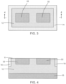
FIG. 3 is a top view of the structure at a fabrication stage subsequent toFIG. 2 . -
FIG. 4 is a cross-sectional view taken generally along line 4-4 inFIG. 3 . -
FIG. 5 is a cross-sectional view of the structure at a fabrication stage subsequent toFIGS. 3, 4 . -
FIG. 6 is a cross-sectional view of a structure in accordance with alternative embodiments of the invention. -
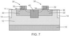
FIG. 7 is a cross-sectional view of a structure in accordance with alternative embodiments of the invention. - With reference to
FIG. 1 and in accordance with embodiments of the invention, asemiconductor layer 12 is positioned on asemiconductor substrate 10. In an embodiment, thesemiconductor substrate 10 may be comprised of a semiconductor material, such as single-crystal silicon. In an embodiment, thesemiconductor layer 12 may be comprised of a porous semiconductor material. In an embodiment, thesemiconductor layer 12 may be comprised of a porous semiconductor material having an electrical resistivity that is greater than the electrical resistivity of the semiconductor material of thesemiconductor substrate 10. In an embodiment, thesemiconductor layer 12 may be comprised of a porous semiconductor material having an electrical resistivity that is greater than 1000 ohm-cm. In an embodiment, the porous semiconductor material contained in thesemiconductor layer 12 may be porous silicon. The porous semiconductor material of thesemiconductor layer 12 may be formed by, for example, electrochemical anodization or chemical etching of the single-crystal semiconductor material of thesemiconductor substrate 10. The porous semiconductor material includes a single-crystal matrix and interconnected pores distributed within the single-crystal matrix. The porous semiconductor material has a porosity characterized by a pore size that may range from a few nanometers to several hundreds of nanometers. The porous semiconductor material is free of crystalline grains and grain boundaries characteristic of a polycrystalline semiconductor material, such as polysilicon. - A shallow
trench isolation region 14 may be formed by a shallow trench isolation technique that patterns trenches in thesemiconductor layer 12 with lithography and etching processes, deposits a dielectric material to overfill the trenches, and planarizes the dielectric material using chemical mechanical polishing and/or an etch back to remove excess dielectric material. The dielectric material contained in the shallowtrench isolation region 14 may be comprised of an electrical insulator, such as silicon dioxide. The shallowtrench isolation region 14 fully surrounds adevice region 16 of thesemiconductor layer 12 in which one or more device structures may be subsequently fabricated. - With reference to
FIG. 2 in which like reference numerals refer to like features inFIG. 1 and at a subsequent fabrication stage,cavities 18 are formed by lithography and etching processes in thesemiconductor layer 12 and inside the boundary of thedevice region 16 surrounded by the shallowtrench isolation region 14. To that end, ahardmask 20 may be formed on atop surface 11 of thesemiconductor layer 12 and patterned to define openings at the intended locations for thecavities 18. An etching process is used to form thecavities 18 after the etch mask is formed, and the etch mask may be stripped by, for example, ashing after thecavities 18 are formed. - Each
cavity 18 includes abottom 24 andsidewalls 26 that extend from thetop surface 11 to thebottom 24. A thickness of the porous semiconductor material of thesemiconductor layer 12 is positioned in a vertical direction between thebottom 24 of eachcavity 18 and thesemiconductor substrate 10. A portion of the porous semiconductor material of thesemiconductor layer 12 is positioned in a lateral direction between eachcavity 18 and the shallowtrench isolation region 14. The porous semiconductor material of thesemiconductor layer 12 includes a portion that is positioned in a lateral direction between thecavities 18. - With reference to
FIGS. 3, 4 in which like reference numerals refer to like features inFIG. 2 and at a subsequent fabrication stage, asemiconductor layer 22 may be formed inside eachcavity 18 with the hardmask 20 (FIG. 2 ) present on the top surface of thesemiconductor layer 12. The semiconductor layers 22, which adopt the shape and dimensions of thecavities 18, may be formed by an epitaxial growth process. The semiconductor layers 22 may be comprised of single-crystal semiconductor material (e.g., single-crystal silicon) that is free of crystalline grains and grain boundaries. The porous semiconductor material of thesemiconductor layer 12 at the bottom 24 and sidewalls 26 of each cavity 18 (FIG. 2 ) serves as a crystalline template for the epitaxial growth of the semiconductor layers 22. The semiconductor layers 22 may be doped during epitaxial growth with a concentration of a dopant, such as an n-type dopant (e.g., arsenic) to provide n-type conductivity. In an embodiment, thesemiconductor layer 12 may be thicker than the semiconductor layers 22. Thehardmask 20 may be removed after forming the semiconductor layers 22. - Each
semiconductor layer 22 is surrounded on multiple sides by the porous semiconductor material of thesemiconductor layer 12. Eachsemiconductor layer 22 may abut and directly contact thesemiconductor layer 12. The porous semiconductor material of thesemiconductor layer 12 is positioned in a vertical direction between eachsemiconductor layer 22 and thesemiconductor substrate 10. The porous semiconductor material of thesemiconductor layer 12 includes a portion that is positioned in a lateral direction between eachsemiconductor layer 22 and the shallowtrench isolation region 14. A portion of the porous semiconductor material of thesemiconductor layer 12 is positioned in a lateral direction between the different semiconductor layers 22. - With reference to
FIG. 5 in which like reference numerals refer to like features inFIGS. 3, 4 and at a subsequent fabrication stage, field-effect transistors 30 may be formed as representative device structures in the semiconductor layers 22. In the representative embodiment, one of the field-effect transistors 30 may be formed in eachsemiconductor layer 22. Each field-effect transistor 30 may include agate electrode 32 and agate dielectric layer 34 formed on the surface of thesemiconductor layer 22 by depositing a layer stack and patterning the layer stack with photolithography and etching processes. Thegate electrode 32 may be comprised of a conductor, such as doped polycrystalline silicon (i.e., polysilicon) or a work function metal, and thegate dielectric layer 34 may be comprised of an electrical insulator, such as silicon dioxide or hafnium oxide. Each field-effect transistor 30 may include source/drain regions 36 positioned in thesemiconductor layer 22. The source/drain regions 36 represent doped regions containing a concentration of a dopant, such as an n-type dopant (e.g., arsenic or phosphorus) that provides n-type conductivity. Alternatively, the source/drain regions 36 may be doped with a concentration of a p-type dopant (e.g., boron) that provides p-type conductivity. As used herein, the term "source/drain region" means a doped region of semiconductor material that can function as either a source or a drain of a field-effect transistor. Eachgate electrode 32 overlaps with a portion of thecorresponding semiconductor layer 22 positioned between the different source/drain regions 36. - The field-
effect transistors 30 are not formed in the porous semiconductor material of thesemiconductor layer 12. Instead, the field-effect transistors 30 are formed in the single-crystal semiconductor material of the semiconductor layers 22, each of which is surrounded on multiple sides by the porous semiconductor material of thesemiconductor layer 12. In an alternative embodiment, one or both of the field-effect transistors 30 may includemultiple gate electrodes 32 and source/drain regions 36 that are arranged relative to themultiple gate electrodes 32 to define a switch field-effect transistor, which may be deployed in a radio-frequency front-end integrated circuit. - In an embodiment, the field-
effect transistors 30 may be constructed as device structures of the same type. In an alternative embodiment, the field-effect transistors 30 may be replaced by another type of device structure that includes one or more doped regions formed in the semiconductor layers 22. In an alternative embodiment, the field-effect transistors 30 may be constructed as different types of transistors, such as a logic field-effect transistor and a switch field-effect transistor. - Performance metrics characterizing the field-
effect transistors 30, which are formed in the single-crystal semiconductor material of the semiconductor layers 22, may be improved because of the porous semiconductor material of thesemiconductor layer 12 that is arranged between the field-effect transistors 30 and thesemiconductor substrate 10. For example, the porous semiconductor material of thesemiconductor layer 12 may operate to reduce the off-capacitance of the field-effect transistors 30. - With reference to
FIG. 6 and in accordance with alternative embodiments of the invention, atrench isolation region 40 may be positioned in thesemiconductor layer 12 at a location between the different semiconductor layers 22. Thetrench isolation region 40 may be comprised of a dielectric material, such as silicon dioxide, that is located inside a trench patterned by lithography and etching processes in thesemiconductor layer 12. In an embodiment, thetrench isolation region 40 may abut and directly contact each of the semiconductor layers 22. In an embodiment, thetrench isolation region 40 and the shallowtrench isolation region 14 may be concurrently formed. - With reference to
FIG. 7 and in accordance with alternative embodiments of the invention, a high-resistivity region 42 may be formed in thesemiconductor layer 12 at a location between the different semiconductor layers 22. In an embodiment, the high-resistivity region 42 may abut and directly contact each of the semiconductor layers 22. The electrical resistivity of the high-resistivity region 42 may be greater than the electrical resistivity of thesemiconductor layer 12. In an embodiment, the high-resistivity region 42 may be comprised of a polycrystalline semiconductor material, such as polysilicon, formed in thesemiconductor layer 12 by a masked ion implantation and a subsequent anneal that recrystallizes the implantation-damaged semiconductor material. - The methods as described above are used in the fabrication of integrated circuit chips. The resulting integrated circuit chips can be distributed by the fabricator in raw wafer form (e.g., as a single wafer that has multiple unpackaged chips), as a bare die, or in a packaged form. The chip may be integrated with other chips, discrete circuit elements, and/or other signal processing devices as part of either an intermediate product or an end product. The end product can be any product that includes integrated circuit chips, such as computer products having a central processor or smartphones.
- References herein to terms modified by language of approximation, such as "about", "approximately", and "substantially", are not to be limited to the precise value specified. The language of approximation may correspond to the precision of an instrument used to measure the value and, unless otherwise dependent on the precision of the instrument, may indicate a range of +/- 10% of the stated value(s).
- References herein to terms such as "vertical", "horizontal", etc. are made by way of example, and not by way of limitation, to establish a frame of reference. The term "horizontal" as used herein is defined as a plane parallel to a conventional plane of a semiconductor substrate, regardless of its actual three-dimensional spatial orientation. The terms "vertical" and "normal" refer to a direction in the frame of reference perpendicular to the horizontal, as just defined. The term "lateral" refers to a direction in the frame of reference within the horizontal plane.
- A feature "connected" or "coupled" to or with another feature may be directly connected or coupled to or with the other feature or, instead, one or more intervening features may be present. A feature may be "directly connected" or "directly coupled" to or with another feature if intervening features are absent. A feature may be "indirectly connected" or "indirectly coupled" to or with another feature if at least one intervening feature is present. A feature "on" or "contacting" another feature may be directly on or in direct contact with the other feature or, instead, one or more intervening features may be present. A feature may be "directly on" or in "direct contact" with another feature if intervening features are absent. A feature may be "indirectly on" or in "indirect contact" with another feature if at least one intervening feature is present. Different features may "overlap" if a feature extends over, and covers a part of, another feature with either direct contact or indirect contact.
- The descriptions of the various embodiments of the present invention have been presented for purposes of illustration but are not intended to be exhaustive or limited to the embodiments disclosed. Many modifications and variations will be apparent to those of ordinary skill in the art without departing from the scope and spirit of the described embodiments. The terminology used herein was chosen to best explain the principles of the embodiments, the practical application or technical improvement over technologies found in the marketplace, or to enable others of ordinary skill in the art to understand the embodiments disclosed herein.
Claims (15)
- A structure comprising:a semiconductor substrate;a first semiconductor layer on the semiconductor substrate, the first semiconductor layer comprising a porous semiconductor material, and the first semiconductor layer including a first cavity;a second semiconductor layer in the first cavity in the first semiconductor layer, the second semiconductor layer comprising a single-crystal semiconductor material; anda first device structure including a first doped region in the second semiconductor layer.
- The structure of claim 1 wherein the first device structure is a field-effect transistor, and the first doped region is a source or a drain of the field-effect transistor.
- The structure of claim 1 or claim 2 wherein the first semiconductor layer abuts the second semiconductor layer, and/or wherein the first semiconductor layer surrounds the second semiconductor layer on multiple sides.
- The structure of one of claims 1 to 3 wherein the porous semiconductor material of the first semiconductor layer is positioned between the second semiconductor layer and the semiconductor substrate.
- The structure of one of claims 1 to 4 wherein the porous semiconductor material is porous silicon, and the single-crystal semiconductor material of the second semiconductor layer is single-crystal silicon.
- The structure of one of claims 1 to 5 wherein the first semiconductor layer includes a second cavity that is spaced in a lateral direction from the first cavity, and further comprising:
a third semiconductor layer in the second cavity in the first semiconductor layer, the third semiconductor layer comprising the single-crystal semiconductor material, and, optionally, a second device structure including a second doped region in the third semiconductor layer. - The structure of claim 6 wherein the first semiconductor layer includes a portion of the porous semiconductor material that is positioned in the lateral direction between the second semiconductor layer and the third semiconductor layer.
- The structure of claim 7 wherein the portion of the first semiconductor layer abuts the second semiconductor layer, and the portion of the first semiconductor layer abuts the third semiconductor layer.
- The structure of one of claims 6 to 8 wherein the porous semiconductor material of the first semiconductor layer is positioned between the second semiconductor layer and the semiconductor substrate, and the porous semiconductor material of the first semiconductor layer is positioned between the third semiconductor layer and the semiconductor substrate.
- The structure of claim 6 further comprising:
a shallow trench isolation region in the first semiconductor layer, the shallow trench isolation region comprising a dielectric material, and the shallow trench isolation region positioned in the lateral direction between the second semiconductor layer and the third semiconductor layer. - The structure of claim 6 wherein the first semiconductor layer has a first electrical resistivity, and further comprising:
a high-resistivity region in the first semiconductor layer, the high-resistivity region having a second electrical resistivity greater than the first electrical resistivity of the first semiconductor layer, and the high-resistivity region positioned in the lateral direction between the second semiconductor layer and the third semiconductor layer. - The structure of one of claims 1 to 11 wherein the semiconductor substrate has a first electrical resistivity, and the first semiconductor layer has a second electrical resistivity that is greater than the first electrical resistivity of the semiconductor substrate, and, optionally, wherein the first semiconductor layer is thicker than the second semiconductor layer.
- The structure of one of claims 1 to 12 wherein the first device structure including a second doped region in the second semiconductor layer, and, optionally, wherein the first device structure includes a gate electrode that overlaps with a portion of the second semiconductor layer positioned between the first doped region and the second doped region.
- A method comprising:forming a cavity in a first semiconductor layer, wherein the first semiconductor layer is positioned on a semiconductor substrate, and the first semiconductor layer comprises a porous semiconductor material;forming a second semiconductor layer in the cavity in the first semiconductor layer, wherein the second semiconductor layer comprises a single-crystal semiconductor material; andforming a device structure including a doped region in the second semiconductor layer.
- The method of claim 14 wherein forming the second semiconductor layer in the cavity in the first semiconductor layer comprises:
epitaxially growing the second semiconductor layer inside the cavity.
Applications Claiming Priority (1)
| Application Number | Priority Date | Filing Date | Title |
|---|---|---|---|
| US17/942,233 US20240088157A1 (en) | 2022-09-12 | 2022-09-12 | Semiconductor device structures isolated by porous semiconductor material |
Publications (1)
| Publication Number | Publication Date |
|---|---|
| EP4336545A1 true EP4336545A1 (en) | 2024-03-13 |
Family
ID=87280340
Family Applications (1)
| Application Number | Title | Priority Date | Filing Date |
|---|---|---|---|
| EP23185154.4A Pending EP4336545A1 (en) | 2022-09-12 | 2023-07-13 | Semiconductor device structures isolated by porous semiconductor material |
Country Status (5)
| Country | Link |
|---|---|
| US (1) | US20240088157A1 (en) |
| EP (1) | EP4336545A1 (en) |
| KR (1) | KR102841392B1 (en) |
| CN (1) | CN117690928A (en) |
| TW (1) | TWI901989B (en) |
Citations (6)
| Publication number | Priority date | Publication date | Assignee | Title |
|---|---|---|---|---|
| GB2038548A (en) * | 1978-10-27 | 1980-07-23 | Nippon Telegraph & Telephone | Isolating semiconductor device by porous silicon oxide |
| US5767561A (en) * | 1997-05-09 | 1998-06-16 | Lucent Technologies Inc. | Integrated circuit device with isolated circuit elements |
| US20010036690A1 (en) * | 1999-04-26 | 2001-11-01 | Mitsubishi Denki Kabushiki Kaisha | Semiconductor device and method of manufacturing the same |
| US20040124439A1 (en) * | 2002-09-04 | 2004-07-01 | Yoshihiro Minami | Semiconductor device having a hollow region and method of manufacturing the same |
| JP2005005321A (en) * | 2003-06-09 | 2005-01-06 | Canon Inc | Semiconductor substrate, semiconductor device and manufacturing method thereof |
| US20210111249A1 (en) * | 2019-10-09 | 2021-04-15 | Newport Fab, Llc Dba Jazz Semiconductor | Semiconductor Structure Having Porous Semiconductor Segment for RF Devices and Bulk Semiconductor Region for Non-RF Devices |
Family Cites Families (1)
| Publication number | Priority date | Publication date | Assignee | Title |
|---|---|---|---|---|
| CN102522424B (en) * | 2011-12-23 | 2014-04-30 | 北京大学 | CMOS device capable of reducing charge sharing effect and manufacturing method thereof |
-
2022
- 2022-09-12 US US17/942,233 patent/US20240088157A1/en active Pending
-
2023
- 2023-07-13 EP EP23185154.4A patent/EP4336545A1/en active Pending
- 2023-08-11 CN CN202311010924.5A patent/CN117690928A/en active Pending
- 2023-08-14 TW TW112130469A patent/TWI901989B/en active
- 2023-08-28 KR KR1020230112557A patent/KR102841392B1/en active Active
Patent Citations (6)
| Publication number | Priority date | Publication date | Assignee | Title |
|---|---|---|---|---|
| GB2038548A (en) * | 1978-10-27 | 1980-07-23 | Nippon Telegraph & Telephone | Isolating semiconductor device by porous silicon oxide |
| US5767561A (en) * | 1997-05-09 | 1998-06-16 | Lucent Technologies Inc. | Integrated circuit device with isolated circuit elements |
| US20010036690A1 (en) * | 1999-04-26 | 2001-11-01 | Mitsubishi Denki Kabushiki Kaisha | Semiconductor device and method of manufacturing the same |
| US20040124439A1 (en) * | 2002-09-04 | 2004-07-01 | Yoshihiro Minami | Semiconductor device having a hollow region and method of manufacturing the same |
| JP2005005321A (en) * | 2003-06-09 | 2005-01-06 | Canon Inc | Semiconductor substrate, semiconductor device and manufacturing method thereof |
| US20210111249A1 (en) * | 2019-10-09 | 2021-04-15 | Newport Fab, Llc Dba Jazz Semiconductor | Semiconductor Structure Having Porous Semiconductor Segment for RF Devices and Bulk Semiconductor Region for Non-RF Devices |
Also Published As
| Publication number | Publication date |
|---|---|
| KR102841392B1 (en) | 2025-08-01 |
| TWI901989B (en) | 2025-10-21 |
| TW202412173A (en) | 2024-03-16 |
| KR20240036458A (en) | 2024-03-20 |
| US20240088157A1 (en) | 2024-03-14 |
| CN117690928A (en) | 2024-03-12 |
Similar Documents
| Publication | Publication Date | Title |
|---|---|---|
| AU2020423612B2 (en) | Nanosheet transistor with self-aligned dielectric pillar | |
| US10832954B2 (en) | Forming a reliable wrap-around contact without source/drain sacrificial regions | |
| US10290712B1 (en) | LDMOS finFET structures with shallow trench isolation inside the fin | |
| US11646235B2 (en) | Vertical tunneling field effect transistor with dual liner bottom spacer | |
| US10121878B1 (en) | LDMOS finFET structures with multiple gate structures | |
| EP4421872A1 (en) | Semiconductor structure with device including at least one in-well porous region | |
| US12176416B2 (en) | Stacked nanosheet transistor with defect free channel | |
| US9722031B2 (en) | Reduced current leakage semiconductor device | |
| US12159926B2 (en) | Lateral bipolar transistor | |
| US20240088157A1 (en) | Semiconductor device structures isolated by porous semiconductor material | |
| EP4443518A1 (en) | Low capacitance and low resistance devices | |
| US12543379B2 (en) | Integrated circuit structure in porous semiconductor region and method to form same | |
| US10325811B2 (en) | Field-effect transistors with fins having independently-dimensioned sections | |
| US10276560B2 (en) | Passive device structure and methods of making thereof | |
| US10784143B2 (en) | Trench isolation preservation during transistor fabrication | |
| US12205949B1 (en) | High-voltage semiconductor device structures | |
| US12349459B1 (en) | High-voltage semiconductor device structures | |
| US11862511B2 (en) | Field-effect transistors with a crystalline body embedded in a trench isolation region | |
| US12446253B2 (en) | Field effect transistor with adjustable effective gate length | |
| US12230673B2 (en) | Field-effect transistors having a gate electrode positioned inside a substrate recess | |
| US20140332927A1 (en) | Self-aligned bipolar junction transistor having self-planarizing isolation raised base structures | |
| CN120129276A (en) | Device for manufacturing sidewalls at preset positions in vertical direction and manufacturing process thereof | |
| CN117995894A (en) | Heterojunction bipolar transistor with amorphous semiconductor region |
Legal Events
| Date | Code | Title | Description |
|---|---|---|---|
| PUAI | Public reference made under article 153(3) epc to a published international application that has entered the european phase |
Free format text: ORIGINAL CODE: 0009012 |
|
| STAA | Information on the status of an ep patent application or granted ep patent |
Free format text: STATUS: THE APPLICATION HAS BEEN PUBLISHED |
|
| AK | Designated contracting states |
Kind code of ref document: A1 Designated state(s): AL AT BE BG CH CY CZ DE DK EE ES FI FR GB GR HR HU IE IS IT LI LT LU LV MC ME MK MT NL NO PL PT RO RS SE SI SK SM TR |
|
| STAA | Information on the status of an ep patent application or granted ep patent |
Free format text: STATUS: REQUEST FOR EXAMINATION WAS MADE |
|
| 17P | Request for examination filed |
Effective date: 20240423 |
|
| RBV | Designated contracting states (corrected) |
Designated state(s): AL AT BE BG CH CY CZ DE DK EE ES FI FR GB GR HR HU IE IS IT LI LT LU LV MC ME MK MT NL NO PL PT RO RS SE SI SK SM TR |