EP4336535A1 - Fuse switch - Google Patents
Fuse switch Download PDFInfo
- Publication number
- EP4336535A1 EP4336535A1 EP23195611.1A EP23195611A EP4336535A1 EP 4336535 A1 EP4336535 A1 EP 4336535A1 EP 23195611 A EP23195611 A EP 23195611A EP 4336535 A1 EP4336535 A1 EP 4336535A1
- Authority
- EP
- European Patent Office
- Prior art keywords
- fuse switch
- guide groove
- pin
- lever
- guide rail
- Prior art date
- Legal status (The legal status is an assumption and is not a legal conclusion. Google has not performed a legal analysis and makes no representation as to the accuracy of the status listed.)
- Pending
Links
- 238000006073 displacement reaction Methods 0.000 abstract description 2
- 230000000694 effects Effects 0.000 description 2
- 230000002349 favourable effect Effects 0.000 description 2
- 238000011022 operating instruction Methods 0.000 description 2
- 238000010276 construction Methods 0.000 description 1
- 238000010616 electrical installation Methods 0.000 description 1
- 230000000284 resting effect Effects 0.000 description 1
Images


Classifications
-
- H—ELECTRICITY
- H01—ELECTRIC ELEMENTS
- H01H—ELECTRIC SWITCHES; RELAYS; SELECTORS; EMERGENCY PROTECTIVE DEVICES
- H01H31/00—Air-break switches for high tension without arc-extinguishing or arc-preventing means
- H01H31/02—Details
- H01H31/12—Adaptation for built-in fuse
- H01H31/122—Fuses mounted on, or constituting the movable contact parts of, the switch
-
- H—ELECTRICITY
- H01—ELECTRIC ELEMENTS
- H01H—ELECTRIC SWITCHES; RELAYS; SELECTORS; EMERGENCY PROTECTIVE DEVICES
- H01H9/00—Details of switching devices, not covered by groups H01H1/00 - H01H7/00
- H01H9/10—Adaptation for built-in fuses
- H01H9/102—Fuses mounted on or constituting the movable contact parts of the switch
Definitions
- the subject of the invention is a fuse switch, especially a detachable, three-phase low voltage strip fuse switch.
- Fuse switches are used to protect electrical installations and to disconnect circuits in a safe and controlled manner. Fuse switches are used in distribution networks of residential and industrial buildings.
- the parked position is a state of the switch in which the fuse cartridges have been slid out from the contacts to a safe distance, thereby opening the circuit(s).
- the manipulator e.g., a lever
- the parked position is a state in which circuits are prevented from being closed by accidentally applying forces to accessible parts of the fuse switch. It is also advantageous to be able to mechanically secure the manipulator (lever) in this position with a padlock or other similar lock.
- the parking action is not very intuitive and requires knowledge of the operating instructions, and above all, it requires carrying out several, often complicated, activities.
- the Polish patent PL215231B1 discloses a switch, especially a detachable, three-phase low voltage strip fuse switch.
- the switch includes a complete base, a complete housing, and a complete drive.
- the housing is equipped with guides into which the drive guidewire strips slide.
- the drive includes a handle and a cap that is slidably mounted in the upper part of the handle.
- there are cutouts on the side surfaces of the handle that cooperate with appropriate pegs placed in the guide.
- the parking state of the switch is obtained by opening the switch and pressing the lock release in the guide and then moving the handle as in the closed position of the switch. Additionally, there is a bow on the front surface of the handle that allows the user to install a mechanical lock or padlock and seal the switch in the closed and parked position.
- a power connection device is known from the description of the Polish patent PL200078B1 .
- the device includes a housing, a busbar terminal, a junction box movable relative to the housing and a switching lever.
- the lever contains side plates on which the pivot plug and bearing plug are arranged.
- the pivot plug is inserted into the first longitudinal recess on the side wall of the housing, and the bearing pin into the second recess, parallel to the first one. This design of the device ensures the possibility of swinging movement of the lever.
- To disconnect the device the lever is grasped and turned clockwise, and the junction box and locking element are pulled upwards.
- the user should tilt the locking element's tilt button to the left, raise the junction box further upwards and then fold the lever to the starting position. In this position, the junction box cannot be pulled further upwards, nor can it be pushed downwards without the reactuation of the locking element.
- European patent document EP1993116B1 covers a fused power switch block.
- the device comprises a lower and an upper part connected to each other via a mounting element. Additionally, a switch cover is attached to the upper part, which has a hole through which a screwdriver can be inserted and directed towards the mounting element.
- the disclosed power switch block also includes a switch lever that is attached to the switch cover. To obtain the opened position, the switching lever must be moved from the closed position to the tilted position. In this arrangement, it is possible to insert a mounting element into the cover without having to dismantle it.
- the technical problem discussed this invention is to propose a fuse switch that will ensure a quick and easy change of the switch into the parked position. Additionally, it is desirable that the parked position of the fuse switch is stable and safe in order to minimize the likelihood of accidental re-closing of the circuits as much as possible. Moreover, it is desirable that the size of the device in the closed position of circuits and in the parked position is small, while maintaining a compact structure. It is also desirable that access to the individual functional elements of the fuse switch in the parked position is quick and easy. In addition, it is desirable that the design of the fuse switch provides the possibility to additionally secure its parked position.
- the subject of the invention is a fuse switch containing a base, a body supported on it, a cassette placed in the body and a lever rotatably connected to the body via a connector, characterized by the fact that it additionally includes a guide rail arranged parallel to the body, with the guide rail on its inner surface, in its central region, is arranged a first pin cooperating with a first guide groove arranged on the side surface of the lever and cooperating with a second guide groove arranged on the side surface of the cassette, the guide rail being able to move vertically relative to the body, the first guide groove being formed from an arc-shaped disconnecting segment and an arc-shaped parking segment.
- the guide rail is additionally capable of being moved horizontally relative to the body.
- the first guide groove is substantially L-shaped.
- the second guide groove is arc-shaped.
- the lever in the closed position of the circuits of the fuse switch, the lever extends substantially parallel to and adjacent to the guide rail which is in the lower position, and the first pin is disposed at the end region of the disconnecting segment and at the first end region of the second guide groove, wherein the lever, in the opened position of circuits of the fuse switch, extends substantially perpendicular to the guide rail which is in a vertically and horizontally displaced position relative to the body, and the first pin is arranged in the connecting region of the disconnecting segment and the parking segment and in the second end region of the second guide groove, wherein the lever, in a position of the parked fuse switch, extends obliquely relative to the guide rail which is in a vertically and horizontally displaced position relative to the body, and the first pin is arranged in an end region of the parking segment and in a second end region of the second guide groove.
- a mounting region is arranged in the second end region of the first guide groove.
- a third guide groove is provided around at least one end of the body, in which a second pin coupled to the cassette is placed.
- the second pin is the axis of the gear wheel, the teeth of which cooperate with the first toothed rack arranged on the inner surface of the body.
- At least one second toothed rack is arranged on the outer surface of the cassette and cooperates with the teeth of the gear wheel.
- a cam is provided on the circumference of the gear wheel which is in contact with the resistance region of the guide rail.
- the cam has a third pin which is positioned in a fourth guide groove disposed in the region of at least one end of the cassette.
- the fuse switch has a structure symmetrical with respect to a vertically oriented plane passing through the longitudinal axis of the fuse switch.
- the fuse switch according to the invention ensures quick and easy change of the switch to the parked position due to the favourable shapes of the construction elements and their functional connection in the form-guide mechanism of the device. Due to the presence of a lever equipped with a first guide groove and a cassette with a second guide groove, which are engaged with the first pin located on the inner surface of the guide rail, it is possible to move the lever in an arc of approximately 140° relative to its lower position, i.e., when the circuits of the fuse switch are closed. This design ensures that the switch can be brought to the parked position with one lever movement. This means that disconnection and parking of the fuse switch is essentially performed in one smooth movement of the lever.
- a set of toothed elements such as the body gear wheel cooperating with the body toothed strip and/or the cassette toothed strip, facilitates efficient movement of the lever in an arc and movement of the guide rail in the horizontal and vertical direction relative to the base. Due to the presence of a second pin in the central region of the gear wheel, which is coupled to the third guide groove of the body, it is possible to guide the vertical movement of the gear wheel and guide rail.
- the third pin of the gear wheel is functionally connected to the resistance region of the guide rail via a hole and the fourth guide groove, thus forming a toothed arm, the operation of which significantly facilitates the movement of the lever in an arc and brings the fuse switch to the parked position.
- the lever In the parked position, the lever is in a diagonal position to the base of the fuse switch with its end resting on the rail, further reducing the likelihood of it accidentally catching and moving the lever back to the down position.
- the dimensions of the fuse switch are such that the device takes up relatively little space and can be installed in hard-to-reach places.
- the lever diagonally to the fuse switch body in the parked position access to the cover is free and ensures easy manipulation of functional elements by the user.
- By arranging the lever diagonally to the base in the parked position it is also possible to secure the movement of the lever by using a padlock or seal, which additionally protects the device against accidental closing of the circuits.
- the opening of circuits is equivalent to the parking of the fuse switch, it is an intuitive operation and does not require careful reading of the user manual.
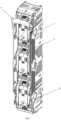
- Fig. 1 shows an axonometric view of the fuse switch in the closed position of circuits
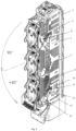
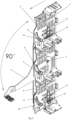
- Fig. 2 shows an axonometric view of the fuse switch in the opened position of circuits
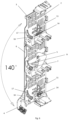
- Fig. 3 shows an axonometric view of the switch fuse in the parked position
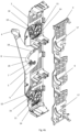
- Fig. 4a shows an exploded view of the form-guide mechanism
- Fig. 4b shows a view of a partially assembled form-guide mechanism
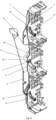
- Fig. 4c shows a view of the assembled form-guide mechanism in the closed position of circuits
- Fig. 5 shows a view of the form-guide mechanism in the opened position of circuits
- Fig. 6 shows a view of the form-guide mechanism in the parked position.
- the fuse switch includes a base 1 on which a body 2 is placed with a cassette 3 provided inside, also including a lever 4, which is functionally connected to the cassette 3 and the body 2. Additionally, the lever 4 is connected to the body 2 via a movable joint 5, which allows for rotational movement of the lever 4.
- the connection of the lever 4 with the cassette 3 and the body 2 is implemented through a system of pins, guide grooves and toothed elements.
- the components of the system connecting the lever 4 with the cassette 3 and the body 2 are present on two opposite sides of the fuse switch in relation to its longitudinal plane and are symmetrical to each other, therefore, for the sake of clarity of disclosure, the structure of one form-guide mechanism will be described in detail.
- the detailed structure and principle of operation of the forming and guiding mechanism of the fuse switch are shown in Fig. 4a - Fig. 6 .
- the device is equipped with a guide rail 6, on the inner surface of which the first pin 7 is arranged, which is coupled with the first guide groove 8 of the lever 4
- the first pin 7 is also functionally connected to the second guide groove 9, which is located on the side surface of the cassette 3.
- the first guide groove 8 resembles the letter L in its shape, while the second guide groove 9 has the shape of an arc.
- the first guide groove 8 is formed by a disconnecting segment 18 and a parking segment 19. Both the disconnecting segment 18 and the parking segment 19 have the shape of an arc.
- the arc radii of the disconnecting segment 18 and the parking segment 19 are not the same.
- the ratio of the value of the arc radius of the parking segment 19 to the value of the arc radius of the disconnecting segment 18 is 0.6, however, this value does not constitute a limitation of the scope of the present invention, and in alternative embodiments it may be smaller or larger, provided that the correct guidance of the first pin 7 is maintained in first guide slot 8.
- the toothed arm includes a gear 11 located on the inner surface of the body 2 with a cam 21 located on its circumference, with gear 11 being functionally connected to a first toothed strip 14 also located on the inner surface of the body 2.
- the cam 21 of the gear 11 is in contact with the resistance region 10 of the guide rail 6.
- the cam 21 is provided with a third pin 16 which is coupled to the guide rail 6 through a hole. Such a mechanism supports the horizontal movement of the guide rail 6.
- the gear wheel 11 is also functionally connected to the second toothed strip 15 located on the outer surface of the cassette 3.
- the gear 11 is provided with a second pin 12 which is coupled to the third guide groove 13 of the body 2 to assist in moving the guide rail 6 in the vertical direction.
- the toothed arm contains the following: a gear wheel 11 placed on the inner surface of the body 2 and coupled to the first toothed strip 14, a cam 21 located on the circumference of the gear wheel 11, a guide rail 6 remaining in contact with the cam 21 via resistance region 10 and, engaged through a hole, a third pin 16, and a cassette 3 which is connected via the fourth guide groove 17 to the third pin 16, wherein the cassette 3 includes on its outer surface a second toothed strip 15 which is coupled to the gear wheel 11.
- Parking the fuse switch is done by pulling the lever and moving it approximately 140° relative to the base 1.
- the cassette 3 is positioned substantially on the base 1, the lever 4 is positioned parallel to the base 1 and the guide rail 6 with its longitudinal edge is adjacent to the edge of the body 2.
- the first pin 7 is located in the first end region of the first guide groove 8 and in the first end region of the second guide groove 9.
- the second pin 12 is located in the first end region of the third guide groove 13 and the third pin 16 is located in the first end region of the fourth guide groove 17.
- the cassette 3 In the opened position of circuits, the cassette 3 is raised as far as possible in the vertical direction relative to the base 1.
- the guide rail 6 also rises in the vertical direction relative to the edge of the body 2 and additionally moves in a horizontal direction relative to the edge of the body 2.
- the first pin 7 moves from the first end region the first guide groove 8 to its corner region, i.e., the connecting region of the disconnecting segment 18 and the parking segment 19. Additionally, the first pin 7 moves from the first end region of the second guide groove 9 moving in an arc to its second end region.
- there is a mounting region 20 which ensures that the first pin 7 is held firmly in place.
- the second pin 12 moves vertically and changes its position so that it is located in the second end region of the third guide groove 13.
- the movement of the lever 4 also causes the third pin 16 to move in an arc in the shape of a sector of a circle with the centre located in the place of the second pin 12, with the simultaneous displacement of both these elements (third pin 16 and second pin 12) in a vertical direction.
- the third pin 16 moves in an arc from the first end region of the fourth guide groove 17 to the second end region thereof.
- the second pin 12 and the third pin 16 do not change position when the fuse switch is moved to the parked position.
- the parked position of the fuse switch is obtained so that the lever is set at an angle of approximately 140° relative to the base 1, and its end is rested on the guide rail 6 so that it slightly protrudes above the upper surface of the guide rail 6.
- the position of the cassette 3 and the guide rail 6 is substantially coincident with their position in the opened position of circuits.
- the first pin 7 remains in the second end region of the second guide groove 9. Due to the movement of the lever 4, the position of the first guide groove 8 relative to the first pin 7 changes, so that the first pin 7 is located in the second end region of the first guide groove 8, in the mounting region 20.
- disconnecting and parking of the fuse switch is performed by one continuous arc movement of the lever 4.
- the cassette 3 moves vertically relative to the base 1 and the guide rail 6 moves horizontally and vertically relative to the base 1.
- the gear wheel 11, which is coupled to the first toothed strip 14 and the second toothed strip 15, moves in a vertical direction relative to the base 1.
- an auxiliary mechanism including a third pin 16 on the cam 21 of the gear wheel 11, disposed in the hole of the guide rail 6, and in the fourth guide groove 17 of the cassette, and an auxiliary mechanism including a second pin 12 disposed in the third guide groove 13 of the body, are arranged in four corner areas of the fuse switch.
- a mechanical lock in the form of a padlock (not shown) is attached to lever 4 to seal the switch in the parked position.
- the fuse switch is a three-phase low-voltage strip fuse switch, but in other embodiments of the invention it may be a fuse switch of a different type, provided that it is ensured that the switch is easily and quickly brought into the parked position by one smooth movement of lever 4.
Landscapes
- Fuses (AREA)
- Details Of Connecting Devices For Male And Female Coupling (AREA)
- Mechanical Control Devices (AREA)
Abstract
The subject of the invention is a fuse switch containing a base (1), a body (2) supported on it, a cassette (3) placed in the body (2) and a lever (4) rotatably connected to the body (2) via a connector (5), characterized by that it additionally includes a guide rail (6) arranged parallel to the body (2), wherein on the inner surface of the guide rail (6) in its central region there is a first pin (7) cooperating with the first guide groove (8) arranged on the side surface of the lever (4) and cooperating with the second guide groove (9) located on the side surface of the cassette (3), the guide rail (6) being capable of vertical displacement relative to the body (2), and the first guide groove (8) is formed from a disconnecting segment (18) in the shape of an arc and a parking segment (19) in the shape of an arc.
Description
- The subject of the invention is a fuse switch, especially a detachable, three-phase low voltage strip fuse switch.
- Fuse switches are used to protect electrical installations and to disconnect circuits in a safe and controlled manner. Fuse switches are used in distribution networks of residential and industrial buildings.
- To gain access to the cover of fuse cartridges, it is necessary to place the fuse switch in the parked position. The parked position is a state of the switch in which the fuse cartridges have been slid out from the contacts to a safe distance, thereby opening the circuit(s). The manipulator (e.g., a lever) used to slide out the cassette is in a position that does not significantly increase the size of the device, so that it is possible to close the switchgear door. The parked position is a state in which circuits are prevented from being closed by accidentally applying forces to accessible parts of the fuse switch. It is also advantageous to be able to mechanically secure the manipulator (lever) in this position with a padlock or other similar lock. In the solutions known from the state of the art, the parking action is not very intuitive and requires knowledge of the operating instructions, and above all, it requires carrying out several, often complicated, activities.
- In known solutions, opening the circuit of the device and parking are two separate activities, and parking requires the user to follow the instructions. When using a fuse switch for a long time, the device's operating instructions are often no longer available and when it is necessary to open the circuit and park it, this operation is much more difficult without the instructions, takes a lot of time, is performed incorrectly or is generally impossible to perform. Therefore, in such cases, disassembly of fuse cartridges is most often performed.
- The Polish patent
PL215231B1 - A power connection device is known from the description of the Polish patent
PL200078B1 - European patent document
EP1993116B1 covers a fused power switch block. The device comprises a lower and an upper part connected to each other via a mounting element. Additionally, a switch cover is attached to the upper part, which has a hole through which a screwdriver can be inserted and directed towards the mounting element. The disclosed power switch block also includes a switch lever that is attached to the switch cover. To obtain the opened position, the switching lever must be moved from the closed position to the tilted position. In this arrangement, it is possible to insert a mounting element into the cover without having to dismantle it. - The technical problem discussed this invention is to propose a fuse switch that will ensure a quick and easy change of the switch into the parked position. Additionally, it is desirable that the parked position of the fuse switch is stable and safe in order to minimize the likelihood of accidental re-closing of the circuits as much as possible. Moreover, it is desirable that the size of the device in the closed position of circuits and in the parked position is small, while maintaining a compact structure. It is also desirable that access to the individual functional elements of the fuse switch in the parked position is quick and easy. In addition, it is desirable that the design of the fuse switch provides the possibility to additionally secure its parked position.
- The subject of the invention is a fuse switch containing a base, a body supported on it, a cassette placed in the body and a lever rotatably connected to the body via a connector, characterized by the fact that it additionally includes a guide rail arranged parallel to the body, with the guide rail on its inner surface, in its central region, is arranged a first pin cooperating with a first guide groove arranged on the side surface of the lever and cooperating with a second guide groove arranged on the side surface of the cassette, the guide rail being able to move vertically relative to the body, the first guide groove being formed from an arc-shaped disconnecting segment and an arc-shaped parking segment.
- Advantageously, the guide rail is additionally capable of being moved horizontally relative to the body.
- More preferably, the first guide groove is substantially L-shaped.
- Even more preferably, the second guide groove is arc-shaped.
- Preferably, in the closed position of the circuits of the fuse switch, the lever extends substantially parallel to and adjacent to the guide rail which is in the lower position, and the first pin is disposed at the end region of the disconnecting segment and at the first end region of the second guide groove, wherein the lever, in the opened position of circuits of the fuse switch, extends substantially perpendicular to the guide rail which is in a vertically and horizontally displaced position relative to the body, and the first pin is arranged in the connecting region of the disconnecting segment and the parking segment and in the second end region of the second guide groove, wherein the lever, in a position of the parked fuse switch, extends obliquely relative to the guide rail which is in a vertically and horizontally displaced position relative to the body, and the first pin is arranged in an end region of the parking segment and in a second end region of the second guide groove.
- More preferably, a mounting region is arranged in the second end region of the first guide groove.
- Even more preferably, a third guide groove is provided around at least one end of the body, in which a second pin coupled to the cassette is placed.
- Equally preferably, the second pin is the axis of the gear wheel, the teeth of which cooperate with the first toothed rack arranged on the inner surface of the body.
- Preferably, at least one second toothed rack is arranged on the outer surface of the cassette and cooperates with the teeth of the gear wheel.
- More preferably, a cam is provided on the circumference of the gear wheel which is in contact with the resistance region of the guide rail.
- Even more preferably, the cam has a third pin which is positioned in a fourth guide groove disposed in the region of at least one end of the cassette.
- Equally preferably, the fuse switch has a structure symmetrical with respect to a vertically oriented plane passing through the longitudinal axis of the fuse switch.
- The fuse switch according to the invention ensures quick and easy change of the switch to the parked position due to the favourable shapes of the construction elements and their functional connection in the form-guide mechanism of the device. Due to the presence of a lever equipped with a first guide groove and a cassette with a second guide groove, which are engaged with the first pin located on the inner surface of the guide rail, it is possible to move the lever in an arc of approximately 140° relative to its lower position, i.e., when the circuits of the fuse switch are closed. This design ensures that the switch can be brought to the parked position with one lever movement. This means that disconnection and parking of the fuse switch is essentially performed in one smooth movement of the lever. Additionally, the L-shaped first guide groove located on the lever with a mounting region located on its second end region, through its shape and the position of the first pin in the parked position, ensures its locking, so that the device is protected against accidental closing of the circuits. Moreover, a set of toothed elements, such as the body gear wheel cooperating with the body toothed strip and/or the cassette toothed strip, facilitates efficient movement of the lever in an arc and movement of the guide rail in the horizontal and vertical direction relative to the base. Due to the presence of a second pin in the central region of the gear wheel, which is coupled to the third guide groove of the body, it is possible to guide the vertical movement of the gear wheel and guide rail. Additionally, the third pin of the gear wheel is functionally connected to the resistance region of the guide rail via a hole and the fourth guide groove, thus forming a toothed arm, the operation of which significantly facilitates the movement of the lever in an arc and brings the fuse switch to the parked position.
- In the parked position, the lever is in a diagonal position to the base of the fuse switch with its end resting on the rail, further reducing the likelihood of it accidentally catching and moving the lever back to the down position. Importantly, the dimensions of the fuse switch are such that the device takes up relatively little space and can be installed in hard-to-reach places. Additionally, by arranging the lever diagonally to the fuse switch body in the parked position, access to the cover is free and ensures easy manipulation of functional elements by the user. By arranging the lever diagonally to the base in the parked position, it is also possible to secure the movement of the lever by using a padlock or seal, which additionally protects the device against accidental closing of the circuits. In the solution according to the invention, the opening of circuits is equivalent to the parking of the fuse switch, it is an intuitive operation and does not require careful reading of the user manual.
- The solution according to the invention is presented in the following embodiments and is illustrated in the drawing, in which
Fig. 1 shows an axonometric view of the fuse switch in the closed position of circuits,Fig. 2 shows an axonometric view of the fuse switch in the opened position of circuits,Fig. 3 shows an axonometric view of the switch fuse in the parked position,Fig. 4a shows an exploded view of the form-guide mechanism,Fig. 4b shows a view of a partially assembled form-guide mechanism,Fig. 4c shows a view of the assembled form-guide mechanism in the closed position of circuits,Fig. 5 shows a view of the form-guide mechanism in the opened position of circuits,Fig. 6 shows a view of the form-guide mechanism in the parked position. - An embodiment of the fuse switch according to the present invention is shown in an axonometric view in
Fig. 1 ,Fig. 2 , andFig. 3 . As shown in the figures, the fuse switch includes abase 1 on which abody 2 is placed with acassette 3 provided inside, also including alever 4, which is functionally connected to thecassette 3 and thebody 2. Additionally, thelever 4 is connected to thebody 2 via amovable joint 5, which allows for rotational movement of thelever 4. The connection of thelever 4 with thecassette 3 and thebody 2 is implemented through a system of pins, guide grooves and toothed elements. Importantly, the components of the system connecting thelever 4 with thecassette 3 and thebody 2 are present on two opposite sides of the fuse switch in relation to its longitudinal plane and are symmetrical to each other, therefore, for the sake of clarity of disclosure, the structure of one form-guide mechanism will be described in detail. - The detailed structure and principle of operation of the forming and guiding mechanism of the fuse switch are shown in
Fig. 4a - Fig. 6 . The device is equipped with aguide rail 6, on the inner surface of which thefirst pin 7 is arranged, which is coupled with thefirst guide groove 8 of thelever 4 Thefirst pin 7 is also functionally connected to thesecond guide groove 9, which is located on the side surface of thecassette 3. Importantly, thefirst guide groove 8 resembles the letter L in its shape, while thesecond guide groove 9 has the shape of an arc. Furthermore, thefirst guide groove 8 is formed by a disconnectingsegment 18 and aparking segment 19. Both the disconnectingsegment 18 and theparking segment 19 have the shape of an arc. The arc radii of the disconnectingsegment 18 and theparking segment 19 are not the same. In this embodiment, the ratio of the value of the arc radius of theparking segment 19 to the value of the arc radius of the disconnectingsegment 18 is 0.6, however, this value does not constitute a limitation of the scope of the present invention, and in alternative embodiments it may be smaller or larger, provided that the correct guidance of thefirst pin 7 is maintained infirst guide slot 8. - An additional element ensuring favourable movement of the
lever 4 in an arc is a toothed arm located near both ends of the fuse switch. The toothed arm includes agear 11 located on the inner surface of thebody 2 with acam 21 located on its circumference, withgear 11 being functionally connected to a firsttoothed strip 14 also located on the inner surface of thebody 2. Thecam 21 of thegear 11 is in contact with theresistance region 10 of theguide rail 6. Thecam 21 is provided with athird pin 16 which is coupled to theguide rail 6 through a hole. Such a mechanism supports the horizontal movement of theguide rail 6. Additionally, thegear wheel 11 is also functionally connected to the secondtoothed strip 15 located on the outer surface of thecassette 3. On the side surface of thecassette 3, near its end, there is an additionalfourth guide groove 17, which is also coupled to thethird pin 16. Furthermore, thegear 11 is provided with asecond pin 12 which is coupled to thethird guide groove 13 of thebody 2 to assist in moving theguide rail 6 in the vertical direction. - Therefore, the toothed arm contains the following: a
gear wheel 11 placed on the inner surface of thebody 2 and coupled to the firsttoothed strip 14, acam 21 located on the circumference of thegear wheel 11, aguide rail 6 remaining in contact with thecam 21 viaresistance region 10 and, engaged through a hole, athird pin 16, and acassette 3 which is connected via thefourth guide groove 17 to thethird pin 16, wherein thecassette 3 includes on its outer surface a secondtoothed strip 15 which is coupled to thegear wheel 11. - Parking the fuse switch is done by pulling the lever and moving it approximately 140° relative to the
base 1. - Importantly, in the closed position of circuits, the
cassette 3 is positioned substantially on thebase 1, thelever 4 is positioned parallel to thebase 1 and theguide rail 6 with its longitudinal edge is adjacent to the edge of thebody 2. Thefirst pin 7 is located in the first end region of thefirst guide groove 8 and in the first end region of thesecond guide groove 9. Additionally, in the closed position of circuits, thesecond pin 12 is located in the first end region of thethird guide groove 13 and thethird pin 16 is located in the first end region of thefourth guide groove 17. - It should be emphasized that when parking the fuse switch, first of all, when the
lever 4 is deflected from the closed position of circuits to approximately 90°, the fuse switch circuits are open. By moving thelever 4 by approximately 90° relative to thebase 1, theguide groove 7 moves in an arc in the shape of a circular segment, the centre of which is located at theconnector 5. - In the opened position of circuits, the
cassette 3 is raised as far as possible in the vertical direction relative to thebase 1. Theguide rail 6 also rises in the vertical direction relative to the edge of thebody 2 and additionally moves in a horizontal direction relative to the edge of thebody 2. Thefirst pin 7 moves from the first end region thefirst guide groove 8 to its corner region, i.e., the connecting region of the disconnectingsegment 18 and theparking segment 19. Additionally, thefirst pin 7 moves from the first end region of thesecond guide groove 9 moving in an arc to its second end region. Importantly, in the second end region of thefirst guide groove 8, there is a mountingregion 20 which ensures that thefirst pin 7 is held firmly in place. - Furthermore, by moving the
lever 4 to the opened position of circuits, thesecond pin 12 moves vertically and changes its position so that it is located in the second end region of thethird guide groove 13. The movement of thelever 4 also causes thethird pin 16 to move in an arc in the shape of a sector of a circle with the centre located in the place of thesecond pin 12, with the simultaneous displacement of both these elements (third pin 16 and second pin 12) in a vertical direction. Additionally, thethird pin 16 moves in an arc from the first end region of thefourth guide groove 17 to the second end region thereof. Thesecond pin 12 and thethird pin 16 do not change position when the fuse switch is moved to the parked position. - Then, after tightening the
lever 4 by approximately 50°, the parked position of the fuse switch is obtained so that the lever is set at an angle of approximately 140° relative to thebase 1, and its end is rested on theguide rail 6 so that it slightly protrudes above the upper surface of theguide rail 6. In the parked position, the position of thecassette 3 and theguide rail 6 is substantially coincident with their position in the opened position of circuits. Thefirst pin 7 remains in the second end region of thesecond guide groove 9. Due to the movement of thelever 4, the position of thefirst guide groove 8 relative to thefirst pin 7 changes, so that thefirst pin 7 is located in the second end region of thefirst guide groove 8, in the mountingregion 20. - Basically, therefore, disconnecting and parking of the fuse switch is performed by one continuous arc movement of the
lever 4. As a result of the movement of the lever by approximately 140° relative to the closed position of circuits, thecassette 3 moves vertically relative to thebase 1 and theguide rail 6 moves horizontally and vertically relative to thebase 1. Additionally, thegear wheel 11, which is coupled to the firsttoothed strip 14 and the secondtoothed strip 15, moves in a vertical direction relative to thebase 1. - In the present embodiment, an auxiliary mechanism including a
third pin 16 on thecam 21 of thegear wheel 11, disposed in the hole of theguide rail 6, and in thefourth guide groove 17 of the cassette, and an auxiliary mechanism including asecond pin 12 disposed in thethird guide groove 13 of the body, are arranged in four corner areas of the fuse switch. - In addition, a mechanical lock in the form of a padlock (not shown) is attached to lever 4 to seal the switch in the parked position.
- In this embodiment, the fuse switch is a three-phase low-voltage strip fuse switch, but in other embodiments of the invention it may be a fuse switch of a different type, provided that it is ensured that the switch is easily and quickly brought into the parked position by one smooth movement of
lever 4. -
- 1 - base,
- 2 - body,
- 3 - cassette,
- 4 - lever,
- 5 - connector,
- 6 - guide rail,
- 7 - first pin,
- 8 - first guide groove,
- 9 - second guide groove,
- 10 - resistance region,
- 11 - gear wheel,
- 12 - second pin,
- 13 - third guide groove,
- 14 - first toothed strip,
- 15 - second toothed strip,
- 16 - third pin,
- 17 - fourth guide groove,
- 18 - disconnecting segment,
- 19 - parking segment,
- 20 - mounting region,
- 21 - cam.
Claims (12)
- A fuse switch comprising a base (1), a body (2) supported thereon, a cassette (3) placed in the body (2) and a lever (4) rotatably connected to the body (2) via a connector (5), characterized in that it additionally includes a guide rail (6) arranged parallel to the body (2), wherein on the inner surface of the guide rail (6) in its central region there is a first pin (7) cooperating with the first guide groove (8) located on the side surface of the lever (4) and cooperating with the second guide groove (9) located on the side surface of the cassette (3), the guide rail (6) having the ability to move vertically relative to the body (2), and the first guide groove (8) is formed from the disconnection segment (18) in the shape of an arc and the parking segment (19) in the shape of an arc.
- Fuse switch according to claim 1, characterized in that the guide rail (6) additionally has the ability to move horizontally in relation to the body (2).
- Fuse switch according to claim 1 or 2, characterized in that the first guide groove (8) is substantially L-shaped.
- Fuse switch according to any of the claims 1-3, characterized in that the second guide groove (9) is in the shape of an arc.
- Fuse switch according to any of the claims 1-4, characterized in that in the close circuit position of the fuse switch, the lever (4) extends substantially parallel and adjacent to the guide rail (6), which is in the lower position, and the first pin (7) is arranged in the end region of the disconnecting segment (18) and in the first end region of the second guide groove (9),wherein the lever (4), in the open circuit position of the fuse switch,extends substantially perpendicular to the guide rail (6), which is in a vertically and horizontally displaced position relative to the body (2), and the first pin (7) is arranged in the connecting region of the disconnecting segment (18) and the parking segment (19) and in the second end region of the second guide groove (9),wherein the lever (4), in the parked position of the fuse switch,extends obliquely relative to the guide rail (6), which is in a vertically and horizontally displaced position relative to the body (2), and the first pin (7) is arranged in the end region of the parking segment (19) and in the second end region of the second guide groove (9).
- Fuse switch according to any of the claims 1-5, characterized in that a mounting region (20) is arranged in the second end region of the first guide groove (8).
- Fuse switch according to any of the claims 1-6, characterized in that in the region of at least one end of the body (2) there is a third guide groove (13), in which a second pin (12) coupled to the cassette (3) is placed.
- Fuse switch according to claim 7, characterized in that the second pin (12) is the axis of the gear wheel (11), the teeth of which cooperate with the first toothed rack (14) arranged on the internal surface of the body (2).
- Fuse switch according to claim 7 or 8, characterized in that at least one second toothed rack (15) is arranged on the outer surface of the cassette (3), which cooperates with the teeth of the gear wheel (11).
- Fuse switch according to claim 8 or 9, characterized in that a cam (21) is placed on the circumference of the gear wheel (11), which is in contact with the resistance region (10) of the guide rail (6).
- Fuse switch according to claim 10, characterized in that the cam (21) has a third pin (16) which is arranged in a fourth guide groove (17) arranged in the region of at least one end of the cassette (3).
- Fuse switch according to any of the claims 1-11, characterized in that it has a symmetrical structure with respect to the vertically oriented plane passing through the longitudinal axis of the fuse switch.
Applications Claiming Priority (1)
| Application Number | Priority Date | Filing Date | Title |
|---|---|---|---|
| PL442216A PL442216A1 (en) | 2022-09-07 | 2022-09-07 | Switch fuse |
Publications (1)
| Publication Number | Publication Date |
|---|---|
| EP4336535A1 true EP4336535A1 (en) | 2024-03-13 |
Family
ID=88647654
Family Applications (1)
| Application Number | Title | Priority Date | Filing Date |
|---|---|---|---|
| EP23195611.1A Pending EP4336535A1 (en) | 2022-09-07 | 2023-09-06 | Fuse switch |
Country Status (2)
| Country | Link |
|---|---|
| EP (1) | EP4336535A1 (en) |
| PL (1) | PL442216A1 (en) |
Citations (6)
| Publication number | Priority date | Publication date | Assignee | Title |
|---|---|---|---|---|
| DE4307459A1 (en) * | 1993-03-10 | 1994-09-15 | Jung Gmbh Albrecht | NH fuse (low-voltage high rupture capacity fuse) load disconnector strip |
| PL200078B1 (en) | 2001-03-27 | 2008-12-31 | Efen Gmbh | Power connection unit |
| EP1993116B1 (en) | 2007-05-04 | 2010-08-18 | EFEN GmbH | Power switch block with fuses |
| EP2428972A2 (en) * | 2010-09-10 | 2012-03-14 | Apator S.A. | Electrical circuit breaker with a blockade to prevent the lid from being removed |
| PL215231B1 (en) | 2007-08-31 | 2013-11-29 | Apator Spolka Akcyjna | Disconnector, especially strip low voltage fuse disconnector |
| EP3671790A1 (en) * | 2018-12-19 | 2020-06-24 | Jean Müller GmbH Elektrotechnische Fabrik | Arrangement of a load bearing element and a cover of a switching block |
-
2022
- 2022-09-07 PL PL442216A patent/PL442216A1/en unknown
-
2023
- 2023-09-06 EP EP23195611.1A patent/EP4336535A1/en active Pending
Patent Citations (6)
| Publication number | Priority date | Publication date | Assignee | Title |
|---|---|---|---|---|
| DE4307459A1 (en) * | 1993-03-10 | 1994-09-15 | Jung Gmbh Albrecht | NH fuse (low-voltage high rupture capacity fuse) load disconnector strip |
| PL200078B1 (en) | 2001-03-27 | 2008-12-31 | Efen Gmbh | Power connection unit |
| EP1993116B1 (en) | 2007-05-04 | 2010-08-18 | EFEN GmbH | Power switch block with fuses |
| PL215231B1 (en) | 2007-08-31 | 2013-11-29 | Apator Spolka Akcyjna | Disconnector, especially strip low voltage fuse disconnector |
| EP2428972A2 (en) * | 2010-09-10 | 2012-03-14 | Apator S.A. | Electrical circuit breaker with a blockade to prevent the lid from being removed |
| EP3671790A1 (en) * | 2018-12-19 | 2020-06-24 | Jean Müller GmbH Elektrotechnische Fabrik | Arrangement of a load bearing element and a cover of a switching block |
Also Published As
| Publication number | Publication date |
|---|---|
| PL442216A1 (en) | 2024-03-11 |
Similar Documents
| Publication | Publication Date | Title |
|---|---|---|
| US4559504A (en) | Fuse terminal | |
| EP2228878B1 (en) | Circuit breaker with apparatus for preventing withdrawing or inserting of carriage of circuit breaker | |
| CN100373519C (en) | Modular fuseholder | |
| EP1296341B1 (en) | Lever fitting-type manual disconnector | |
| CA2683775A1 (en) | Installation switchgear having a spring-loaded terminal arrangement | |
| US5406449A (en) | Pullout type electric disconnect switch | |
| KR20030090765A (en) | Low voltage switchgear comprising a locking device for an appliance module | |
| CA1079334A (en) | Drawout switchgear with levering-in mechanism | |
| JPH0510004B2 (en) | ||
| US4489362A (en) | Electric switchboard apparatus with a breaker-fuse interlock | |
| US10811209B2 (en) | Switching mechanism of circuit breaker | |
| EP4336535A1 (en) | Fuse switch | |
| JPH04298934A (en) | Actuating-handle guard of breaker for wiring | |
| US4823231A (en) | Current tapping device disconnectable from an omnibus bar distribution column | |
| US3179761A (en) | Electrical switch and fuse housing combination having a pivotally mounted adapting mechanism operable independently of its movable cover | |
| US20060061439A1 (en) | Circuit breaker with a moveable plug contact | |
| GB2141295A (en) | Electrical assembly and drive means for a movable structure therein | |
| JPH0361967B2 (en) | ||
| WO2015020785A1 (en) | Hidden/sliding door system for field-installed accessory access | |
| JP4059984B2 (en) | Circuit breaker removal device | |
| US3278710A (en) | Circuit interrupting device with a movable arc-hood | |
| GB1362828A (en) | Enclosed switchgear | |
| JP3853245B2 (en) | Plug-in circuit breaker | |
| JP3659610B2 (en) | Drawer type circuit breaker shutter device | |
| JPH09204856A (en) | Switching device |
Legal Events
| Date | Code | Title | Description |
|---|---|---|---|
| PUAI | Public reference made under article 153(3) epc to a published international application that has entered the european phase |
Free format text: ORIGINAL CODE: 0009012 |
|
| STAA | Information on the status of an ep patent application or granted ep patent |
Free format text: STATUS: REQUEST FOR EXAMINATION WAS MADE |
|
| 17P | Request for examination filed |
Effective date: 20230906 |
|
| AK | Designated contracting states |
Kind code of ref document: A1 Designated state(s): AL AT BE BG CH CY CZ DE DK EE ES FI FR GB GR HR HU IE IS IT LI LT LU LV MC ME MK MT NL NO PL PT RO RS SE SI SK SM TR |