EP4336160B1 - Dynamic recalibration of optical air data system - Google Patents
Dynamic recalibration of optical air data system Download PDFInfo
- Publication number
- EP4336160B1 EP4336160B1 EP23179707.7A EP23179707A EP4336160B1 EP 4336160 B1 EP4336160 B1 EP 4336160B1 EP 23179707 A EP23179707 A EP 23179707A EP 4336160 B1 EP4336160 B1 EP 4336160B1
- Authority
- EP
- European Patent Office
- Prior art keywords
- air data
- pressure
- optical
- static
- data system
- Prior art date
- Legal status (The legal status is an assumption and is not a legal conclusion. Google has not performed a legal analysis and makes no representation as to the accuracy of the status listed.)
- Active
Links
Images


Classifications
-
- G—PHYSICS
- G01—MEASURING; TESTING
- G01L—MEASURING FORCE, STRESS, TORQUE, WORK, MECHANICAL POWER, MECHANICAL EFFICIENCY, OR FLUID PRESSURE
- G01L15/00—Devices or apparatus for measuring two or more fluid pressure values simultaneously
-
- G—PHYSICS
- G01—MEASURING; TESTING
- G01P—MEASURING LINEAR OR ANGULAR SPEED, ACCELERATION, DECELERATION, OR SHOCK; INDICATING PRESENCE, ABSENCE, OR DIRECTION, OF MOVEMENT
- G01P5/00—Measuring speed of fluids, e.g. of air stream; Measuring speed of bodies relative to fluids, e.g. of ship, of aircraft
- G01P5/14—Measuring speed of fluids, e.g. of air stream; Measuring speed of bodies relative to fluids, e.g. of ship, of aircraft by measuring differences of pressure in the fluid
- G01P5/16—Measuring speed of fluids, e.g. of air stream; Measuring speed of bodies relative to fluids, e.g. of ship, of aircraft by measuring differences of pressure in the fluid using Pitot tubes, e.g. Machmeter
-
- G—PHYSICS
- G01—MEASURING; TESTING
- G01L—MEASURING FORCE, STRESS, TORQUE, WORK, MECHANICAL POWER, MECHANICAL EFFICIENCY, OR FLUID PRESSURE
- G01L11/00—Measuring steady or quasi-steady pressure of a fluid or a fluent solid material by means not provided for in group G01L7/00 or G01L9/00
- G01L11/02—Measuring steady or quasi-steady pressure of a fluid or a fluent solid material by means not provided for in group G01L7/00 or G01L9/00 by optical means
-
- G—PHYSICS
- G01—MEASURING; TESTING
- G01L—MEASURING FORCE, STRESS, TORQUE, WORK, MECHANICAL POWER, MECHANICAL EFFICIENCY, OR FLUID PRESSURE
- G01L19/00—Details of, or accessories for, apparatus for measuring steady or quasi-steady pressure of a fluent medium insofar as such details or accessories are not special to particular types of pressure gauges
- G01L19/0092—Pressure sensor associated with other sensors, e.g. for measuring acceleration or temperature
-
- G—PHYSICS
- G01—MEASURING; TESTING
- G01L—MEASURING FORCE, STRESS, TORQUE, WORK, MECHANICAL POWER, MECHANICAL EFFICIENCY, OR FLUID PRESSURE
- G01L27/00—Testing or calibrating of apparatus for measuring fluid pressure
- G01L27/002—Calibrating, i.e. establishing true relation between transducer output value and value to be measured, zeroing, linearising or span error determination
-
- G—PHYSICS
- G01—MEASURING; TESTING
- G01P—MEASURING LINEAR OR ANGULAR SPEED, ACCELERATION, DECELERATION, OR SHOCK; INDICATING PRESENCE, ABSENCE, OR DIRECTION, OF MOVEMENT
- G01P21/00—Testing or calibrating of apparatus or devices covered by the preceding groups
-
- G—PHYSICS
- G01—MEASURING; TESTING
- G01S—RADIO DIRECTION-FINDING; RADIO NAVIGATION; DETERMINING DISTANCE OR VELOCITY BY USE OF RADIO WAVES; LOCATING OR PRESENCE-DETECTING BY USE OF THE REFLECTION OR RERADIATION OF RADIO WAVES; ANALOGOUS ARRANGEMENTS USING OTHER WAVES
- G01S17/00—Systems using the reflection or reradiation of electromagnetic waves other than radio waves, e.g. lidar systems
- G01S17/88—Lidar systems specially adapted for specific applications
Definitions
- Optical air data systems can measure air density because of the proportionality between the air density and the molecular signal backscatter intensity. If the air temperature is also known, the static air pressure can be calculated with the Ideal Gas Law. Calculating static air density and pressure from the molecular signal backscatter intensity is performed using conversion coefficients.
- the conversion coefficients are determined from various quantities, such as laser power, transmitter-receiver alignment, aperture size, and optical element throughput. In general, these quantities may vary due to known or unknown effects. Therefore, the conversion coefficients may need to be calibrated frequently. Current approaches require regular system recalibration, which requires the need for certified devices and causes high maintenance costs.
- EP3301456 and US2016/305977 disclose system comprising a pressure air data system mounted on a vehicle.
- a system comprises a pressure air data system mounted on a vehicle and including one or more non-optical air data sensors, wherein the one or more non-optical air data sensors are configured to interrogate a region of interest outside of the vehicle to determine a first set of air data measurements comprising at least a first static air pressure.
- the system also includes an optical air data system mounted on the vehicle and comprising one or more optical air data sensors, wherein the one or more optical air data sensors are configured to interrogate the region of interest to determine a second set of air data measurements comprising at least a second static air pressure.
- the second static air pressure is determined using one or more conversion coefficients.
- At least one system processor is operatively coupled to the pressure air data system and the optical air data system.
- the system processor is operative to receive and process the first static air pressure from the pressure air data system; receive and process the second static air pressure from the optical air data system; dynamically recalibrate the one or more conversion coefficients by computing at least one correction factor for the optical air data system; send the correction factor to the optical air data system to update the second static air pressure; and output an optimized static air pressure based on the first static air pressure and the updated second static air pressure.
- the optical air data system is configured to be used as a backup in case of failure of the pressure air data system.
- the present approach provides a method for dynamic recalibration of the optical air data system. This provides a reduction in the cost of regular maintenance calibration, while improving the performance of the optical air data system.
- the present optical air data system can be used as a backup in case of failure of a legacy air data system such as a pressure air data system.
- the dynamic recalibration of the optical air data system enables a required performance of the optical air data system so it can be used as the main air data system in case of failure of the pressure air data system.
- FIG. 1 is a block diagram of a system 100 for dynamic recalibration, according to one embodiment.
- the system 100 generally comprises a pressure air data system 110 onboard a vehicle 102, such as an aircraft, and an optical air data system 120 onboard vehicle 102.
- An onboard system processor 130 is in operative communication with pressure air data system 110, and with optical air data system 120.
- the system processor 130 can include or be in communication with one or more memory units (not shown), which are configured to store program instructions and data.
- the pressure air data system 110 includes one or more non-optical air data sensors 112, and at least one static pressure processor 114 operatively coupled to non-optical air data sensors 112.
- the non-optical air data sensors 112 are configured to interrogate an atmospheric region of interest 118 outside of vehicle 102, and to provide sensor data to static pressure processor 114, which determines a first set of air data measurements comprising at least a first static air pressure 116.
- non-optical air data sensors 112 can include one or more static pressure sensors such as pitot tubes, static ports, or the like.
- one or more temperature sensors 115 can be optionally employed in pressure air data system 110.
- the optical air data system 120 includes one or more optical air data sensors 122, and at least one optical air data processor 124 operatively coupled to optical air data sensors 122.
- the optical air data sensors 122 are configured to interrogate region of interest 118, and to provide sensor data to optical air data processor 124, which determines a second set of air data measurements comprising at least a second static air pressure 128.
- the second static air pressure 128 is determined using one or more conversion coefficients 126, as discussed in further detail hereafter.
- optical air data sensors 122 can include one or more light detection and ranging (LiDAR) sensors, which are configured to transmit light into region of interest 118, and collect a scattered portion of the transmitted light from region of interest 118.
- LiDAR light detection and ranging
- one or more temperature sensors 119 can be optionally employed in optical air data system 120.
- the system processor 130 is operative to receive and process the first static air pressure 116 from pressure air data system 110.
- the system processor 130 is also operative to receive and process the second static air pressure 128 from optical air data system 120.
- processor 130 hosts a Kalman filter 132, which can be used to dynamically recalibrate conversion coefficients 126 by computing a correction factor 134, which is output to optical air data system 120.
- the Kalman filter 132 is also operative to estimate a best static pressure output from pressure air data system 110 and optical air data system 120. Further details related to the Kalman filter are discussed hereafter.
- the correction factor 134 is applied to recalibrate conversion coefficients 126 such that an updated second static air pressure 128 is output by optical air data system 120 in the next measurement cycle.
- the processor 130 outputs an optimized static air pressure 140 based on the first static air pressure 116 from pressure air data system 110, and the updated second static air pressure 128 from optical air data system 120.
- the optical air data system 120 can also be configured as a backup air data system in case of failure of pressure air data system 110.
- FIG. 3 is a block diagram of a system 300 for dynamic recalibration using a Kalman filter, according to another embodiment.
- the system 300 generally comprises a pressure air data system 310 onboard a vehicle, and an onboard optical air data system 320.
- An onboard system processor 330 is in operative communication with pressure air data system 310, and with optical air data system 320.
- the pressure air data system 310 includes non-optical air data sensors configured to interrogate an atmospheric region of interest outside of the vehicle, and to provide sensor data that is used to determine a first static air pressure.
- the optical air data system 320 includes optical air data sensors configured to interrogate the region of interest, and to provide sensor data that is used to determine a second static air pressure.
- the second static air pressure is determined using one or more conversion coefficients, as described previously.
- the correction factor is applied to recalibrate the conversion coefficients such that an updated second static air pressure is output by optical air data system 320 in a next measurement cycle.
- the processor 330 outputs an optimized static air pressure based on the first static air pressure from pressure air data system 310, and the updated second static air pressure from optical air data system 330.
- FIG. 4 is a flow diagram of an exemplary method 400 for dynamic recalibration of an optical air data system, which is employed in conjunction with a pressure air data system onboard a vehicle such as an aircraft.
- the pressure air data system includes non-optical air data sensors, and the optical air data system includes optical air data sensors.
- the method 400 comprises interrogating a region of interest outside of the vehicle, using the non-optical air data sensors, to determine a first set of air data measurements that includes a first static air pressure (block 410); and interrogating the region of interest, using the optical air data sensors, to determine a second set of air data measurements that includes a second static air pressure (block 412).
- the second static air pressure is determined using one or more conversion coefficients saved in a memory of the optical air data system.
- the method 400 further comprises receiving, in a processor, the first static air pressure from the pressure air data system (block 414); and receiving, in the processor, the second static air pressure from the optical air data system (block 416). Thereafter, method 400 computes, in the processor, at least one correction factor for the one or more conversion coefficients in the optical air data system (block 418). The method 400 then sends the at least one correction factor to the optical air data system to dynamically recalibrate the one or more conversion coefficients (block 420). The method 400 performs updating of the second static air pressure in a next measurement cycle using the recalibrated one or more conversion coefficients (block 422). Subsequently, method 400 comprises outputting, from the processor, an optimized static air pressure based on the first static air pressure and the updated second static air pressure (block 424).
- the processing units and/or other computational devices used in systems and methods described herein may be implemented using software, firmware, hardware, or appropriate combinations thereof.
- the processing unit and/or other computational devices may be supplemented by, or incorporated in, specially-designed application-specific integrated circuits (ASICs) or field programmable gate arrays (FPGAs).
- ASICs application-specific integrated circuits
- FPGAs field programmable gate arrays
- the processing unit and/or other computational devices may communicate through an additional transceiver with other computing devices outside of the system, such as those associated with a management system or computing devices associated with other subsystems controlled by the management system.
- the processing unit and/or other computational devices can also include or function with software programs, firmware, or other computer readable instructions for carrying out various process tasks, calculations, and control functions used in the methods and systems described herein.
- program modules include routines, programs, objects, data components, data structures, algorithms, and the like, which perform particular tasks or implement particular abstract data types.
- Instructions for carrying out the various process tasks, calculations, and generation of other data used in the operation of the methods described herein can be implemented in software, firmware, or other computer readable instructions. These instructions are typically stored on appropriate computer program products that include computer readable media used for storage of computer readable instructions or data structures. Such a computer readable medium may be available media that can be accessed by a general purpose or special purpose computer or processor, or any programmable logic device.
- Suitable computer readable storage media may include, for example, nonvolatile memory devices including semi-conductor memory devices such as Random Access Memory (RAM), Read Only Memory (ROM), Electrically Erasable Programmable ROM (EEPROM), or flash memory devices; magnetic disks such as internal hard disks or removable disks; optical storage devices such as compact discs (CDs), digital versatile discs (DVDs), Blu-ray discs; or any other media that can be used to carry or store desired program code in the form of computer executable instructions or data structures.
- RAM Random Access Memory
- ROM Read Only Memory
- EEPROM Electrically Erasable Programmable ROM
- flash memory devices such as electrically Erasable Programmable ROM (EEPROM), or flash memory devices
- magnetic disks such as internal hard disks or removable disks
- optical storage devices such as compact discs (CDs), digital versatile discs (DVDs), Blu-ray discs
- CDs compact discs
- DVDs digital versatile discs
Landscapes
- Physics & Mathematics (AREA)
- General Physics & Mathematics (AREA)
- Engineering & Computer Science (AREA)
- Computer Networks & Wireless Communication (AREA)
- Electromagnetism (AREA)
- Radar, Positioning & Navigation (AREA)
- Remote Sensing (AREA)
- Aviation & Aerospace Engineering (AREA)
- Chemical & Material Sciences (AREA)
- Analytical Chemistry (AREA)
- Measuring Fluid Pressure (AREA)
Description
- The project leading to this application has received funding from the Clean Sky 2 Joint Undertaking under the European Union's Horizon 2020 research and innovation program under grant agreement No. 807097.
- Optical air data systems can measure air density because of the proportionality between the air density and the molecular signal backscatter intensity. If the air temperature is also known, the static air pressure can be calculated with the Ideal Gas Law. Calculating static air density and pressure from the molecular signal backscatter intensity is performed using conversion coefficients. The conversion coefficients are determined from various quantities, such as laser power, transmitter-receiver alignment, aperture size, and optical element throughput. In general, these quantities may vary due to known or unknown effects. Therefore, the conversion coefficients may need to be calibrated frequently. Current approaches require regular system recalibration, which requires the need for certified devices and causes high maintenance costs.
EP3301456 andUS2016/305977 disclose system comprising a pressure air data system mounted on a vehicle. - A system comprises a pressure air data system mounted on a vehicle and including one or more non-optical air data sensors, wherein the one or more non-optical air data sensors are configured to interrogate a region of interest outside of the vehicle to determine a first set of air data measurements comprising at least a first static air pressure. The system also includes an optical air data system mounted on the vehicle and comprising one or more optical air data sensors, wherein the one or more optical air data sensors are configured to interrogate the region of interest to determine a second set of air data measurements comprising at least a second static air pressure. The second static air pressure is determined using one or more conversion coefficients. At least one system processor is operatively coupled to the pressure air data system and the optical air data system. The system processor is operative to receive and process the first static air pressure from the pressure air data system; receive and process the second static air pressure from the optical air data system; dynamically recalibrate the one or more conversion coefficients by computing at least one correction factor for the optical air data system; send the correction factor to the optical air data system to update the second static air pressure; and output an optimized static air pressure based on the first static air pressure and the updated second static air pressure. The optical air data system is configured to be used as a backup in case of failure of the pressure air data system.
- Features of the present invention will become apparent to those skilled in the art from the following description with reference to the drawings. Understanding that the drawings depict only typical embodiments and are not therefore to be considered limiting in scope, the invention will be described with additional specificity and detail through the use of the accompanying drawings, in which:
-
Figure 1 is a block diagram of a system for dynamic recalibration of an optical air data system, according to one embodiment; -
Figure 2 is a flow diagram of a method for dynamic recalibration of an optical air data system, according to one implementation; -
Figure 3 is a block diagram of a system for dynamic recalibration of an optical air data system, according to another embodiment; and -
Figure 4 is a flow diagram of a method for dynamic recalibration of an optical air data system, according to another implementation. - In the following detailed description, embodiments are described in sufficient detail to enable those skilled in the art to practice the invention. It is to be understood that other embodiments may be utilized without departing from the scope of the invention. The following detailed description is, therefore, not to be taken in a limiting sense.
- A method and system for dynamic recalibration of an optical air data system is described herein.
- In order to use an optical air data system to obtain air data measurements such as static air pressure, calibration of conversion coefficients is needed. The calibration needs to be done frequently in order to provide signal outputs with a required precision. The present approach provides a method for dynamic recalibration of the optical air data system. This provides a reduction in the cost of regular maintenance calibration, while improving the performance of the optical air data system.
- The present optical air data system can be used as a backup in case of failure of a legacy air data system such as a pressure air data system. The dynamic recalibration of the optical air data system enables a required performance of the optical air data system so it can be used as the main air data system in case of failure of the pressure air data system.
- Further details regarding the present approach are described as follows and with reference to the drawings.
-
Figure 1 is a block diagram of asystem 100 for dynamic recalibration, according to one embodiment. Thesystem 100 generally comprises a pressureair data system 110 onboard avehicle 102, such as an aircraft, and an opticalair data system 120onboard vehicle 102. Anonboard system processor 130 is in operative communication with pressureair data system 110, and with opticalair data system 120. Thesystem processor 130 can include or be in communication with one or more memory units (not shown), which are configured to store program instructions and data. - The pressure
air data system 110 includes one or more non-opticalair data sensors 112, and at least onestatic pressure processor 114 operatively coupled to non-opticalair data sensors 112. The non-opticalair data sensors 112 are configured to interrogate an atmospheric region ofinterest 118 outside ofvehicle 102, and to provide sensor data tostatic pressure processor 114, which determines a first set of air data measurements comprising at least a firststatic air pressure 116. - In example embodiments, non-optical
air data sensors 112 can include one or more static pressure sensors such as pitot tubes, static ports, or the like. In addition, one ormore temperature sensors 115 can be optionally employed in pressureair data system 110. - The optical
air data system 120 includes one or more optical air data sensors 122, and at least one opticalair data processor 124 operatively coupled to optical air data sensors 122. The optical air data sensors 122 are configured to interrogate region ofinterest 118, and to provide sensor data to opticalair data processor 124, which determines a second set of air data measurements comprising at least a secondstatic air pressure 128. The secondstatic air pressure 128 is determined using one ormore conversion coefficients 126, as discussed in further detail hereafter. - In example embodiments, optical air data sensors 122 can include one or more light detection and ranging (LiDAR) sensors, which are configured to transmit light into region of
interest 118, and collect a scattered portion of the transmitted light from region ofinterest 118. In addition, one ormore temperature sensors 119 can be optionally employed in opticalair data system 120. - The
system processor 130 is operative to receive and process the firststatic air pressure 116 from pressureair data system 110. Thesystem processor 130 is also operative to receive and process the secondstatic air pressure 128 from opticalair data system 120. In one embodiment,processor 130 hosts a Kalmanfilter 132, which can be used to dynamically recalibrateconversion coefficients 126 by computing acorrection factor 134, which is output to opticalair data system 120. The Kalmanfilter 132 is also operative to estimate a best static pressure output from pressureair data system 110 and opticalair data system 120. Further details related to the Kalman filter are discussed hereafter. - The
correction factor 134 is applied to recalibrateconversion coefficients 126 such that an updated secondstatic air pressure 128 is output by opticalair data system 120 in the next measurement cycle. Theprocessor 130 outputs an optimizedstatic air pressure 140 based on the firststatic air pressure 116 from pressureair data system 110, and the updated secondstatic air pressure 128 from opticalair data system 120. - The optical
air data system 120 can also be configured as a backup air data system in case of failure of pressureair data system 110. - During operation of
system 100, opticalair data system 120 can compute the static air pressure from a molecular signal backscatter intensity using the ideal gas law, expressed as:
- Because the optical air data system is not directly measuring the number of air molecules, but rather the molecular signal backscatter intensity, the number of air molecules can be calculated as:

- where Nm is the molecular signal backscatter intensity and C is the conversion constant. Using both the pressure air data system and the optical air data system enables to calculate molecular signal backscatter intensity to number of molecules conversion coefficients, expressed as:

- where P ref-1 is the static air pressure measured by the pressure air data system in a previous measurement cycle, and P calc-1 is the static air pressure calculated as:

-
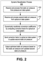
Figure 2 is a functional flow diagram of adynamic recalibration process 200 performed by a Kalman filter, according to an exemplary implementation. Inprocess 200, the Kaman filter is operative to receive and process a first static air pressure from the pressure air data system (block 210); and receive and process a second static air pressure from the optical air data system (block 212). Thereafter, the Kalman filter dynamically recalibrates conversion coefficients by computing a correction factor for the optical air data system (block 214), based on the first and second static air pressures. The Kalman filter sends the correction factor to the optical air data system to update the second static air pressure in a next measurement cycle (block 216). Subsequently, the Kalman filter outputs an optimized static air pressure based on the first static air pressure and the updated second static air pressure (block 218). -
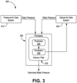
Figure 3 is a block diagram of asystem 300 for dynamic recalibration using a Kalman filter, according to another embodiment. Thesystem 300 generally comprises a pressureair data system 310 onboard a vehicle, and an onboard opticalair data system 320. Anonboard system processor 330 is in operative communication with pressureair data system 310, and with opticalair data system 320. - The pressure
air data system 310 includes non-optical air data sensors configured to interrogate an atmospheric region of interest outside of the vehicle, and to provide sensor data that is used to determine a first static air pressure. The opticalair data system 320 includes optical air data sensors configured to interrogate the region of interest, and to provide sensor data that is used to determine a second static air pressure. The second static air pressure is determined using one or more conversion coefficients, as described previously. - The
system processor 330 is operative to receive and process the first static air pressure from pressureair data system 310, and the second static air pressure from opticalair data system 320. Theprocessor 330 hosts aKalman filter 332, which is used to dynamically recalibrate the conversion coefficients. TheKalman filter 332 includes aprediction module 334, and acorrection module 336 configured to receive an output fromprediction module 334. Theprediction module 334 is configured to receive and process the first and second static air pressures. Thecorrection module 336 receives the output fromprediction module 334, which is used to compute a correction factor for recalibrating the conversion coefficients. A correction signal corresponding to the correction factor is sent fromcorrection module 336 to an input of opticalair data system 320. - The correction factor is applied to recalibrate the conversion coefficients such that an updated second static air pressure is output by optical
air data system 320 in a next measurement cycle. Theprocessor 330 outputs an optimized static air pressure based on the first static air pressure from pressureair data system 310, and the updated second static air pressure from opticalair data system 330. -
Figure 4 is a flow diagram of anexemplary method 400 for dynamic recalibration of an optical air data system, which is employed in conjunction with a pressure air data system onboard a vehicle such as an aircraft. The pressure air data system includes non-optical air data sensors, and the optical air data system includes optical air data sensors. Themethod 400 comprises interrogating a region of interest outside of the vehicle, using the non-optical air data sensors, to determine a first set of air data measurements that includes a first static air pressure (block 410); and interrogating the region of interest, using the optical air data sensors, to determine a second set of air data measurements that includes a second static air pressure (block 412). The second static air pressure is determined using one or more conversion coefficients saved in a memory of the optical air data system. Themethod 400 further comprises receiving, in a processor, the first static air pressure from the pressure air data system (block 414); and receiving, in the processor, the second static air pressure from the optical air data system (block 416). Thereafter,method 400 computes, in the processor, at least one correction factor for the one or more conversion coefficients in the optical air data system (block 418). Themethod 400 then sends the at least one correction factor to the optical air data system to dynamically recalibrate the one or more conversion coefficients (block 420). Themethod 400 performs updating of the second static air pressure in a next measurement cycle using the recalibrated one or more conversion coefficients (block 422). Subsequently,method 400 comprises outputting, from the processor, an optimized static air pressure based on the first static air pressure and the updated second static air pressure (block 424). - The processing units and/or other computational devices used in systems and methods described herein may be implemented using software, firmware, hardware, or appropriate combinations thereof. The processing unit and/or other computational devices may be supplemented by, or incorporated in, specially-designed application-specific integrated circuits (ASICs) or field programmable gate arrays (FPGAs). In some implementations, the processing unit and/or other computational devices may communicate through an additional transceiver with other computing devices outside of the system, such as those associated with a management system or computing devices associated with other subsystems controlled by the management system. The processing unit and/or other computational devices can also include or function with software programs, firmware, or other computer readable instructions for carrying out various process tasks, calculations, and control functions used in the methods and systems described herein.
- The methods described herein may be implemented by computer executable instructions, such as program modules or components, which are executed by at least one processor or processing unit. Generally, program modules include routines, programs, objects, data components, data structures, algorithms, and the like, which perform particular tasks or implement particular abstract data types.
- Instructions for carrying out the various process tasks, calculations, and generation of other data used in the operation of the methods described herein can be implemented in software, firmware, or other computer readable instructions. These instructions are typically stored on appropriate computer program products that include computer readable media used for storage of computer readable instructions or data structures. Such a computer readable medium may be available media that can be accessed by a general purpose or special purpose computer or processor, or any programmable logic device.
- Suitable computer readable storage media may include, for example, nonvolatile memory devices including semi-conductor memory devices such as Random Access Memory (RAM), Read Only Memory (ROM), Electrically Erasable Programmable ROM (EEPROM), or flash memory devices; magnetic disks such as internal hard disks or removable disks; optical storage devices such as compact discs (CDs), digital versatile discs (DVDs), Blu-ray discs; or any other media that can be used to carry or store desired program code in the form of computer executable instructions or data structures.
Claims (10)
- A system comprising:a pressure air data system mounted on a vehicle and comprising one or more non-optical air data sensors, wherein the one or more non-optical air data sensors are configured to interrogate a region of interest outside of the vehicle to determine a first set of air data measurements comprising at least a first static air pressure;an optical air data system mounted on the vehicle and comprising one or more optical air data sensors, wherein the one or more optical air data sensors are configured to interrogate the region of interest to determine a second set of air data measurements comprising at least a second static air pressure, wherein the second static air pressure is determined using one or more conversion coefficients; andat least one system processor operatively coupled to the pressure air data system and the optical air data system, the at least one system processor operative to:receive and process the first static air pressure from the pressure air data system;receive and process the second static air pressure from the optical air data system;wherein the optical air data system is configured as a backup system in case of failure of the pressure air data systemcharacterized in that said one system processor is further operative to dynamically recalibrate the one or more conversion coefficients by computing at least one correction factor for the optical air data system;send the correction factor to the optical air data system to update the second static air pressure; andoutput an optimized static air pressure based on the first static air pressure and the updated second static air pressure.
- The system of claim 1, wherein the one or more non-optical air data sensors comprise one or more static pressure sensors.
- The system of claim 2, wherein the one or more static pressure sensors comprise one or more pitot tubes, one or more static pressure ports, or combinations thereof.
- The system of claim 1, wherein the pressure air data system further comprises one or more temperature sensors.
- The system of claim 1, wherein the pressure air data system further comprises at least one static pressure processor operatively coupled to the one or more non-optical air data sensors.
- The system of claim 1, wherein the one or more optical air data sensors comprise one or more light detection and ranging (LiDAR) sensors.
- The system of claim 1, wherein the optical air data system further comprises one or more temperature sensors.
- The system of claim 1, wherein the optical air data system further comprises at least one optical air data processor operatively coupled to the one or more optical air data sensors.
- The system of claim 1, wherein the at least one system processor hosts a Kalman filter that is operative to dynamically recalibrate the one or more conversion coefficients by computing the at least one correction factor for the optical air data system;
wherein the at least one correction factor is applied by the optical air data system to recalibrate the one or more conversion coefficients used to update the second static air pressure in a next measurement cycle. - A method comprising:providing a pressure air data system comprising one or more non-optical air data sensors, onboard a vehicle;providing an optical air data system comprising one or more optical air data sensors, onboard the vehicle;interrogating a region of interest outside of the vehicle, using the one or more non-optical air data sensors, to determine a first set of air data measurements comprising a first static air pressure;interrogating the region of interest, using the one or more optical air data sensors, to determine a second set of air data measurements comprising a second static air pressure, wherein the second static air pressure is determined in the optical air data system using one or more conversion coefficients;receiving, in a processor, the first static air pressure from the pressure air data system;receiving, in the processor, the second static air pressure from the optical air data system;computing, in the processor, at least one correction factor for the one or more conversion coefficients;sending the at least one correction factor to the optical air data system to dynamically recalibrate the one or more conversion coefficients;updating the second static air pressure in a next measurement cycle using the recalibrated one or more conversion coefficients; andoutputting, from the processor, an optimized static air pressure based on the first static air pressure and the updated second static air pressure.
Applications Claiming Priority (1)
| Application Number | Priority Date | Filing Date | Title |
|---|---|---|---|
| US17/903,721 US12339296B2 (en) | 2022-09-06 | 2022-09-06 | Dynamic recalibration of optical air data system |
Publications (2)
| Publication Number | Publication Date |
|---|---|
| EP4336160A1 EP4336160A1 (en) | 2024-03-13 |
| EP4336160B1 true EP4336160B1 (en) | 2024-12-18 |
Family
ID=86861969
Family Applications (1)
| Application Number | Title | Priority Date | Filing Date |
|---|---|---|---|
| EP23179707.7A Active EP4336160B1 (en) | 2022-09-06 | 2023-06-16 | Dynamic recalibration of optical air data system |
Country Status (3)
| Country | Link |
|---|---|
| US (1) | US12339296B2 (en) |
| EP (1) | EP4336160B1 (en) |
| JP (1) | JP2024037135A (en) |
Family Cites Families (33)
| Publication number | Priority date | Publication date | Assignee | Title |
|---|---|---|---|---|
| US6273370B1 (en) | 1999-11-01 | 2001-08-14 | Lockheed Martin Corporation | Method and system for estimation and correction of angle-of-attack and sideslip angle from acceleration measurements |
| US7106447B2 (en) * | 2002-03-01 | 2006-09-12 | Michigan Aerospace Corporation | Molecular optical air data systems (MOADS) |
| US7495774B2 (en) | 2002-03-01 | 2009-02-24 | Michigan Aerospace Corporation | Optical air data system |
| US6894768B2 (en) * | 2002-08-02 | 2005-05-17 | Ophir Corporation | Optical air data systems and methods |
| US6928341B2 (en) * | 2003-05-13 | 2005-08-09 | The Boeing Company | Computational air data system for angle-of-attack and angle-of-sideslip |
| US8508721B2 (en) * | 2009-08-18 | 2013-08-13 | The Boeing Company | Multifunction aircraft LIDAR |
| US8527233B2 (en) | 2010-09-27 | 2013-09-03 | The Boeing Company | Airspeed sensing system for an aircraft |
| US8908160B2 (en) * | 2011-12-23 | 2014-12-09 | Optical Air Data Systems, Llc | Optical air data system suite of sensors |
| US10352813B2 (en) * | 2013-09-30 | 2019-07-16 | University Corporation For Atmospheric Research | Calibration of aircraft instruments using a laser sensor |
| US10473684B2 (en) * | 2014-10-17 | 2019-11-12 | Nokia Technologies Oy | Method and apparatus for providing movement detection based on air pressure data |
| FR3035209B1 (en) | 2015-04-20 | 2018-10-05 | Thales | MULTIFUNCTION PROBE FOR PRIMARY REFERENCES FOR AIRCRAFT, MEASUREMENT SYSTEM, AIRCRAFT AND METHOD FOR OBTAINING PHYSICAL SIZES |
| US9451414B1 (en) * | 2015-09-22 | 2016-09-20 | Cisco Technology, Inc. | Automatically determining relative locations of collaboration endpoints within a building |
| US10444367B2 (en) | 2016-02-26 | 2019-10-15 | Honeywell International Inc. | Enhanced LiDAR air data using supplementary sensor outputs |
| US20170276790A1 (en) | 2016-03-22 | 2017-09-28 | Honeywell International Inc. | Hybrid air data systems using lidar and legacy air data sensors |
| JP7122978B2 (en) * | 2016-07-06 | 2022-08-22 | オフィル コーポレイション | Optical air data system and method |
| US10775504B2 (en) * | 2016-09-29 | 2020-09-15 | Honeywell International Inc. | Laser air data sensor mounting and operation for eye safety |
| US10598789B2 (en) | 2016-09-29 | 2020-03-24 | Honeywell International Inc. | Mounting a laser transceiver to an aircraft |
| US20180120439A1 (en) * | 2016-11-03 | 2018-05-03 | Honeywell International Inc. | Systems and methods for using dissimilar lidar technologies |
| US10591312B2 (en) * | 2017-02-08 | 2020-03-17 | Honeywell International Inc. | Whispering gallery mode based range-resolved air data system |
| US10241198B2 (en) * | 2017-03-30 | 2019-03-26 | Luminar Technologies, Inc. | Lidar receiver calibration |
| US11508247B2 (en) * | 2017-07-27 | 2022-11-22 | Honeywell International Inc. | Lidar-based aircraft collision avoidance system |
| EP3710902B1 (en) * | 2017-11-14 | 2024-03-27 | Gulfstream Aerospace Corporation | Conversion between calibrated airspeed and true airspeed in trajectory modeling |
| US10527724B2 (en) * | 2017-12-19 | 2020-01-07 | Honeywell International Inc. | Compensation of an optical air data system using inertial aiding |
| US10822109B2 (en) * | 2018-01-05 | 2020-11-03 | The Boeing Company | Methods and systems for determining airspeed of an aircraft |
| US20190217966A1 (en) | 2018-01-12 | 2019-07-18 | Rosemount Aerospace Inc. | Aircraft air data generation using laser sensor data and inertial sensor data |
| DE102018127804B4 (en) * | 2018-11-07 | 2024-07-25 | Vc Viii Polytech Holding Aps | Improving or optimising the yield of a wind turbine by detecting a flow stall |
| US11169173B2 (en) | 2019-05-15 | 2021-11-09 | Rosemount Aerospace Inc. | Air data system architectures including laser air data and acoustic air data sensors |
| CN110346605B (en) | 2019-08-01 | 2021-05-07 | 中国商用飞机有限责任公司 | Method and system for aircraft airspeed calibration based on static pressure error correction |
| US11428820B1 (en) * | 2019-09-16 | 2022-08-30 | Lockheed Martin Corporation | Method to determine airborne lidar installation angles using ground returns and INS/GPS data |
| US11774594B2 (en) * | 2020-06-23 | 2023-10-03 | Honeywell International Inc. | Air data system with optical modulator on receive channels for stroboscopic detection |
| US11754484B2 (en) * | 2020-09-22 | 2023-09-12 | Honeywell International Inc. | Optical air data system fusion with remote atmospheric sensing |
| US11851193B2 (en) * | 2020-11-20 | 2023-12-26 | Rosemount Aerospace Inc. | Blended optical and vane synthetic air data architecture |
| US11435234B1 (en) * | 2021-02-10 | 2022-09-06 | Quantum Valley Ideas Laboratories | Increasing the measurement precision of optical instrumentation using Kalman-type filters |
-
2022
- 2022-09-06 US US17/903,721 patent/US12339296B2/en active Active
-
2023
- 2023-06-16 EP EP23179707.7A patent/EP4336160B1/en active Active
- 2023-07-03 JP JP2023109380A patent/JP2024037135A/en active Pending
Also Published As
| Publication number | Publication date |
|---|---|
| EP4336160A1 (en) | 2024-03-13 |
| JP2024037135A (en) | 2024-03-18 |
| US20240077511A1 (en) | 2024-03-07 |
| US12339296B2 (en) | 2025-06-24 |
Similar Documents
| Publication | Publication Date | Title |
|---|---|---|
| EP3223020A1 (en) | Hybrid air data system using lidar and legacy air data sensors | |
| JP5460148B2 (en) | Positioning device and program | |
| EP3620995A1 (en) | Method and apparatus for determining static state of obstacle | |
| CN110579778B (en) | Signal fault detection for global navigation satellite system using multiple antennas | |
| EP3971585B1 (en) | Optical air data system fusion with remote atmospheric sensing | |
| CN107153187B (en) | Ultrasonic distance correction | |
| US9030356B2 (en) | Positioning system receiver sensor system coupled with measurement data output | |
| US6374190B2 (en) | Method for calibrating an angle sensor and navigation system having an angle sensor | |
| US11525841B2 (en) | System and method for deriving airspeed from a particle sensor | |
| CN113093239B (en) | Method, corresponding system and program product for providing navigation information | |
| EP3561502B1 (en) | Gas concentration measuring device and method of calibrating same | |
| CN111492258A (en) | Method and device for determining the installation angle between the road on which a vehicle is driving and the measurement or detection direction of a radar sensor | |
| EP3786671A1 (en) | Handling of araim terrain database induced errors | |
| KR101107219B1 (en) | Navigation method of aircraft and inertial navigation device filter and navigation system using same | |
| EP1271118A1 (en) | Method and apparatus for measuring temperature of movable object | |
| EP4336160A1 (en) | Dynamic recalibration of optical air data system | |
| EP4307012A1 (en) | Gnss measurement processing and residual error model estimation | |
| US11762104B2 (en) | Method and device for locating a vehicle | |
| US20150052969A1 (en) | Calibrating a Device | |
| FR3010801A1 (en) | METHOD AND DEVICE FOR DETERMINING AT LEAST ONE VERTICAL TOTAL ELECTRONIC CONTENT SPECIFIC TO A SUPPORT POINT | |
| WO2024203667A1 (en) | Vehicle speed estimating device, position calculating device, and program | |
| WO2025103686A1 (en) | Validation method and validation system for reference positioning system, receiver, and storage medium | |
| US20230408312A1 (en) | Method for ascertaining a fluid pressure in a fluid supply network for fluid and ultrasonic fluid meters, and ultrasonic fluid meter | |
| EP1186981B1 (en) | Offline apparatus for detecting attitude of artificial satellite in wide-band and method thereof | |
| EP3598145B1 (en) | Pitot static systems with angle of sideslip determination and compensation |
Legal Events
| Date | Code | Title | Description |
|---|---|---|---|
| PUAI | Public reference made under article 153(3) epc to a published international application that has entered the european phase |
Free format text: ORIGINAL CODE: 0009012 |
|
| STAA | Information on the status of an ep patent application or granted ep patent |
Free format text: STATUS: THE APPLICATION HAS BEEN PUBLISHED |
|
| AK | Designated contracting states |
Kind code of ref document: A1 Designated state(s): AL AT BE BG CH CY CZ DE DK EE ES FI FR GB GR HR HU IE IS IT LI LT LU LV MC ME MK MT NL NO PL PT RO RS SE SI SK SM TR |
|
| STAA | Information on the status of an ep patent application or granted ep patent |
Free format text: STATUS: REQUEST FOR EXAMINATION WAS MADE |
|
| 17P | Request for examination filed |
Effective date: 20240328 |
|
| RBV | Designated contracting states (corrected) |
Designated state(s): AL AT BE BG CH CY CZ DE DK EE ES FI FR GB GR HR HU IE IS IT LI LT LU LV MC ME MK MT NL NO PL PT RO RS SE SI SK SM TR |
|
| GRAP | Despatch of communication of intention to grant a patent |
Free format text: ORIGINAL CODE: EPIDOSNIGR1 |
|
| STAA | Information on the status of an ep patent application or granted ep patent |
Free format text: STATUS: GRANT OF PATENT IS INTENDED |
|
| RIC1 | Information provided on ipc code assigned before grant |
Ipc: G01L 19/00 20060101ALI20240619BHEP Ipc: G01L 11/02 20060101ALI20240619BHEP Ipc: G01L 27/00 20060101ALI20240619BHEP Ipc: G01L 15/00 20060101AFI20240619BHEP |
|
| INTG | Intention to grant announced |
Effective date: 20240711 |
|
| GRAS | Grant fee paid |
Free format text: ORIGINAL CODE: EPIDOSNIGR3 |
|
| GRAA | (expected) grant |
Free format text: ORIGINAL CODE: 0009210 |
|
| STAA | Information on the status of an ep patent application or granted ep patent |
Free format text: STATUS: THE PATENT HAS BEEN GRANTED |
|
| AK | Designated contracting states |
Kind code of ref document: B1 Designated state(s): AL AT BE BG CH CY CZ DE DK EE ES FI FR GB GR HR HU IE IS IT LI LT LU LV MC ME MK MT NL NO PL PT RO RS SE SI SK SM TR |
|
| REG | Reference to a national code |
Ref country code: CH Ref legal event code: EP |
|
| REG | Reference to a national code |
Ref country code: DE Ref legal event code: R096 Ref document number: 602023001398 Country of ref document: DE |
|
| REG | Reference to a national code |
Ref country code: IE Ref legal event code: FG4D |
|
| P01 | Opt-out of the competence of the unified patent court (upc) registered |
Free format text: CASE NUMBER: APP_3839/2025 Effective date: 20250123 |
|
| REG | Reference to a national code |
Ref country code: LT Ref legal event code: MG9D |
|
| PG25 | Lapsed in a contracting state [announced via postgrant information from national office to epo] |
Ref country code: HR Free format text: LAPSE BECAUSE OF FAILURE TO SUBMIT A TRANSLATION OF THE DESCRIPTION OR TO PAY THE FEE WITHIN THE PRESCRIBED TIME-LIMIT Effective date: 20241218 |
|
| PG25 | Lapsed in a contracting state [announced via postgrant information from national office to epo] |
Ref country code: FI Free format text: LAPSE BECAUSE OF FAILURE TO SUBMIT A TRANSLATION OF THE DESCRIPTION OR TO PAY THE FEE WITHIN THE PRESCRIBED TIME-LIMIT Effective date: 20241218 |
|
| PG25 | Lapsed in a contracting state [announced via postgrant information from national office to epo] |
Ref country code: BG Free format text: LAPSE BECAUSE OF FAILURE TO SUBMIT A TRANSLATION OF THE DESCRIPTION OR TO PAY THE FEE WITHIN THE PRESCRIBED TIME-LIMIT Effective date: 20241218 |
|
| PG25 | Lapsed in a contracting state [announced via postgrant information from national office to epo] |
Ref country code: NO Free format text: LAPSE BECAUSE OF FAILURE TO SUBMIT A TRANSLATION OF THE DESCRIPTION OR TO PAY THE FEE WITHIN THE PRESCRIBED TIME-LIMIT Effective date: 20250318 |
|
| REG | Reference to a national code |
Ref country code: NL Ref legal event code: MP Effective date: 20241218 |
|
| PG25 | Lapsed in a contracting state [announced via postgrant information from national office to epo] |
Ref country code: GR Free format text: LAPSE BECAUSE OF FAILURE TO SUBMIT A TRANSLATION OF THE DESCRIPTION OR TO PAY THE FEE WITHIN THE PRESCRIBED TIME-LIMIT Effective date: 20250319 Ref country code: LV Free format text: LAPSE BECAUSE OF FAILURE TO SUBMIT A TRANSLATION OF THE DESCRIPTION OR TO PAY THE FEE WITHIN THE PRESCRIBED TIME-LIMIT Effective date: 20241218 |
|
| PG25 | Lapsed in a contracting state [announced via postgrant information from national office to epo] |
Ref country code: RS Free format text: LAPSE BECAUSE OF FAILURE TO SUBMIT A TRANSLATION OF THE DESCRIPTION OR TO PAY THE FEE WITHIN THE PRESCRIBED TIME-LIMIT Effective date: 20250318 |
|
| PG25 | Lapsed in a contracting state [announced via postgrant information from national office to epo] |
Ref country code: NL Free format text: LAPSE BECAUSE OF FAILURE TO SUBMIT A TRANSLATION OF THE DESCRIPTION OR TO PAY THE FEE WITHIN THE PRESCRIBED TIME-LIMIT Effective date: 20241218 |
|
| REG | Reference to a national code |
Ref country code: AT Ref legal event code: MK05 Ref document number: 1752567 Country of ref document: AT Kind code of ref document: T Effective date: 20241218 |
|
| PG25 | Lapsed in a contracting state [announced via postgrant information from national office to epo] |
Ref country code: SM Free format text: LAPSE BECAUSE OF FAILURE TO SUBMIT A TRANSLATION OF THE DESCRIPTION OR TO PAY THE FEE WITHIN THE PRESCRIBED TIME-LIMIT Effective date: 20241218 |
|
| PG25 | Lapsed in a contracting state [announced via postgrant information from national office to epo] |
Ref country code: PL Free format text: LAPSE BECAUSE OF FAILURE TO SUBMIT A TRANSLATION OF THE DESCRIPTION OR TO PAY THE FEE WITHIN THE PRESCRIBED TIME-LIMIT Effective date: 20241218 |
|
| PG25 | Lapsed in a contracting state [announced via postgrant information from national office to epo] |
Ref country code: ES Free format text: LAPSE BECAUSE OF FAILURE TO SUBMIT A TRANSLATION OF THE DESCRIPTION OR TO PAY THE FEE WITHIN THE PRESCRIBED TIME-LIMIT Effective date: 20241218 |
|
| PG25 | Lapsed in a contracting state [announced via postgrant information from national office to epo] |
Ref country code: IS Free format text: LAPSE BECAUSE OF FAILURE TO SUBMIT A TRANSLATION OF THE DESCRIPTION OR TO PAY THE FEE WITHIN THE PRESCRIBED TIME-LIMIT Effective date: 20250418 |
|
| PG25 | Lapsed in a contracting state [announced via postgrant information from national office to epo] |
Ref country code: PT Free format text: LAPSE BECAUSE OF FAILURE TO SUBMIT A TRANSLATION OF THE DESCRIPTION OR TO PAY THE FEE WITHIN THE PRESCRIBED TIME-LIMIT Effective date: 20250421 |
|
| PG25 | Lapsed in a contracting state [announced via postgrant information from national office to epo] |
Ref country code: EE Free format text: LAPSE BECAUSE OF FAILURE TO SUBMIT A TRANSLATION OF THE DESCRIPTION OR TO PAY THE FEE WITHIN THE PRESCRIBED TIME-LIMIT Effective date: 20241218 |
|
| PGFP | Annual fee paid to national office [announced via postgrant information from national office to epo] |
Ref country code: FR Payment date: 20250624 Year of fee payment: 3 |
|
| PG25 | Lapsed in a contracting state [announced via postgrant information from national office to epo] |
Ref country code: RO Free format text: LAPSE BECAUSE OF FAILURE TO SUBMIT A TRANSLATION OF THE DESCRIPTION OR TO PAY THE FEE WITHIN THE PRESCRIBED TIME-LIMIT Effective date: 20241218 Ref country code: AT Free format text: LAPSE BECAUSE OF FAILURE TO SUBMIT A TRANSLATION OF THE DESCRIPTION OR TO PAY THE FEE WITHIN THE PRESCRIBED TIME-LIMIT Effective date: 20241218 |
|
| PG25 | Lapsed in a contracting state [announced via postgrant information from national office to epo] |
Ref country code: SK Free format text: LAPSE BECAUSE OF FAILURE TO SUBMIT A TRANSLATION OF THE DESCRIPTION OR TO PAY THE FEE WITHIN THE PRESCRIBED TIME-LIMIT Effective date: 20241218 |
|
| PG25 | Lapsed in a contracting state [announced via postgrant information from national office to epo] |
Ref country code: CZ Free format text: LAPSE BECAUSE OF FAILURE TO SUBMIT A TRANSLATION OF THE DESCRIPTION OR TO PAY THE FEE WITHIN THE PRESCRIBED TIME-LIMIT Effective date: 20241218 |
|
| PG25 | Lapsed in a contracting state [announced via postgrant information from national office to epo] |
Ref country code: IT Free format text: LAPSE BECAUSE OF FAILURE TO SUBMIT A TRANSLATION OF THE DESCRIPTION OR TO PAY THE FEE WITHIN THE PRESCRIBED TIME-LIMIT Effective date: 20241218 |
|
| PG25 | Lapsed in a contracting state [announced via postgrant information from national office to epo] |
Ref country code: SE Free format text: LAPSE BECAUSE OF FAILURE TO SUBMIT A TRANSLATION OF THE DESCRIPTION OR TO PAY THE FEE WITHIN THE PRESCRIBED TIME-LIMIT Effective date: 20241218 |
|
| REG | Reference to a national code |
Ref country code: DE Ref legal event code: R097 Ref document number: 602023001398 Country of ref document: DE |
|
| PG25 | Lapsed in a contracting state [announced via postgrant information from national office to epo] |
Ref country code: DK Free format text: LAPSE BECAUSE OF FAILURE TO SUBMIT A TRANSLATION OF THE DESCRIPTION OR TO PAY THE FEE WITHIN THE PRESCRIBED TIME-LIMIT Effective date: 20241218 |
|
| PLBE | No opposition filed within time limit |
Free format text: ORIGINAL CODE: 0009261 |
|
| STAA | Information on the status of an ep patent application or granted ep patent |
Free format text: STATUS: NO OPPOSITION FILED WITHIN TIME LIMIT |
|
| 26N | No opposition filed |
Effective date: 20250919 |
|
| REG | Reference to a national code |
Ref country code: DE Ref legal event code: R119 Ref document number: 602023001398 Country of ref document: DE |
|
| PG25 | Lapsed in a contracting state [announced via postgrant information from national office to epo] |
Ref country code: MC Free format text: LAPSE BECAUSE OF FAILURE TO SUBMIT A TRANSLATION OF THE DESCRIPTION OR TO PAY THE FEE WITHIN THE PRESCRIBED TIME-LIMIT Effective date: 20241218 |
|
| PG25 | Lapsed in a contracting state [announced via postgrant information from national office to epo] |
Ref country code: LU Free format text: LAPSE BECAUSE OF NON-PAYMENT OF DUE FEES Effective date: 20250616 |
|
| REG | Reference to a national code |
Ref country code: BE Ref legal event code: MM Effective date: 20250630 |
|
| PG25 | Lapsed in a contracting state [announced via postgrant information from national office to epo] |
Ref country code: DE Free format text: LAPSE BECAUSE OF NON-PAYMENT OF DUE FEES Effective date: 20260101 Ref country code: IE Free format text: LAPSE BECAUSE OF NON-PAYMENT OF DUE FEES Effective date: 20250616 |
|
| PG25 | Lapsed in a contracting state [announced via postgrant information from national office to epo] |
Ref country code: BE Free format text: LAPSE BECAUSE OF NON-PAYMENT OF DUE FEES Effective date: 20250630 |